EP0649773A1 - Automotive headlamp assembly fastening system - Google Patents
Automotive headlamp assembly fastening system Download PDFInfo
- Publication number
- EP0649773A1 EP0649773A1 EP94115013A EP94115013A EP0649773A1 EP 0649773 A1 EP0649773 A1 EP 0649773A1 EP 94115013 A EP94115013 A EP 94115013A EP 94115013 A EP94115013 A EP 94115013A EP 0649773 A1 EP0649773 A1 EP 0649773A1
- Authority
- EP
- European Patent Office
- Prior art keywords
- mounting
- lock plate
- openings
- support panel
- lamp
- Prior art date
- Legal status (The legal status is an assumption and is not a legal conclusion. Google has not performed a legal analysis and makes no representation as to the accuracy of the status listed.)
- Granted
Links
Images

Classifications
-
- B—PERFORMING OPERATIONS; TRANSPORTING
- B60—VEHICLES IN GENERAL
- B60Q—ARRANGEMENT OF SIGNALLING OR LIGHTING DEVICES, THE MOUNTING OR SUPPORTING THEREOF OR CIRCUITS THEREFOR, FOR VEHICLES IN GENERAL
- B60Q1/00—Arrangement of optical signalling or lighting devices, the mounting or supporting thereof or circuits therefor
- B60Q1/02—Arrangement of optical signalling or lighting devices, the mounting or supporting thereof or circuits therefor the devices being primarily intended to illuminate the way ahead or to illuminate other areas of way or environments
- B60Q1/04—Arrangement of optical signalling or lighting devices, the mounting or supporting thereof or circuits therefor the devices being primarily intended to illuminate the way ahead or to illuminate other areas of way or environments the devices being headlights
- B60Q1/0408—Arrangement of optical signalling or lighting devices, the mounting or supporting thereof or circuits therefor the devices being primarily intended to illuminate the way ahead or to illuminate other areas of way or environments the devices being headlights built into the vehicle body, e.g. details concerning the mounting of the headlamps on the vehicle body
- B60Q1/0441—Arrangement of optical signalling or lighting devices, the mounting or supporting thereof or circuits therefor the devices being primarily intended to illuminate the way ahead or to illuminate other areas of way or environments the devices being headlights built into the vehicle body, e.g. details concerning the mounting of the headlamps on the vehicle body the housing being fastened onto the vehicle body using means other than screws
-
- Y—GENERAL TAGGING OF NEW TECHNOLOGICAL DEVELOPMENTS; GENERAL TAGGING OF CROSS-SECTIONAL TECHNOLOGIES SPANNING OVER SEVERAL SECTIONS OF THE IPC; TECHNICAL SUBJECTS COVERED BY FORMER USPC CROSS-REFERENCE ART COLLECTIONS [XRACs] AND DIGESTS
- Y10—TECHNICAL SUBJECTS COVERED BY FORMER USPC
- Y10T—TECHNICAL SUBJECTS COVERED BY FORMER US CLASSIFICATION
- Y10T24/00—Buckles, buttons, clasps, etc.
- Y10T24/45—Separable-fastener or required component thereof [e.g., projection and cavity to complete interlock]
- Y10T24/45225—Separable-fastener or required component thereof [e.g., projection and cavity to complete interlock] including member having distinct formations and mating member selectively interlocking therewith
- Y10T24/45984—Cavity having specific shape
- Y10T24/4599—Cavity having specific shape including closed elongated access opening for guiding transverse projection travel after insertion
Definitions
- the subject invention is directed toward the art of automotive vehicle headlamps and, more particularly, to a headlamp mounting arrangement that greatly simplifies installation and removal of automotive headlamp assemblies.
- Vehicle headlamps are typically mounted by means of bolts and nuts or similar threaded fasteners. Consequently, installation and removal of headlamp assemblies has generally required the use of tools and has been time consuming and relatively difficult.
- a lamp mounting arrangement for a vehicle and includes a mounting support panel forming a part of the vehicle.
- a lamp assembly having a rear exterior wall with a plurality of mounting studs extending therefrom is arranged to be releasably joined to the support panel.
- the mounting studs each have an outer end portion with an enlarged head that extends through aligned first openings in the support panel.
- a lock plate is connected to the mounting support panel on the side of the mounting support panel opposite the lamp assembly for sliding movement between a first position for preventing withdrawal of the mounting studs from the first openings in the mounting support panel, and a second position for permitting withdrawal of the mounting studs from the first openings.
- Latch means are formed on the lock plate for limiting undesired sliding movement of the lock plate in a direction toward the second position.
- the lock plate includes slotted portions which engage between the enlarged heads and the mounting support panel.
- the latch means are associated with the slotted portions and are arranged to engage the enlarged head on at least one mounting stud.
- the latch means include a resilient shoulder adjacent the slotted portions with the resilient shoulder positioned and arranged to engage the enlarged head of the studs and prevent movement of the lock plate until the resilient shoulder is manually deflected or a predetermined force is applied.
- the lock plate is connected to the mounting support panel by resilient post elements which extend from the lock plate through second openings formed in the mounting support panel.
- the second openings are elongated slots sized to permit sliding movement of the lock plate between the first and second positions.
- the lock plate is a unitary plate member molded from plastics material.
- the lamp assembly merely requires that the stud portions be extended through the openings in the mounting support panel which can be a portion of the vehicle body panels. Thereafter, the lock plate is positioned on the opposite side over the studs and slid laterally to the lock position. To remove the headlamp assembly, it is merely necessary to deflect the latch means on the lock plate and slide the latch plate to the first or release position. Normally, however, the lock plate is firmly latched in position and the resilient nature of the lock means maintains a firm bias on the headlamp assembly to maintain it locked firmly in position and to prevent undesired release movement of the lock plate.
- a primary object of the invention is the provision of a simple yet rigid headlamp mounting assembly which can be manually installed and released without the use of tools or special equipment.
- Yet another object of the invention is the provision of an assembly of the type described which allows a single molded plastic lock plate assembly to cooperate with a body panel to provide firm mounting of the headlamp assembly.
- a still further object is the provision of a fastening assembly of the type described which is simple and inexpensive but highly reliable in functioning.
- FIGURE 1 best illustrates the overall arrangement of the subject invention.
- the FIGURE 1 showing is a pictorial illustration of the major components of the system in an exploded, disassembled relationship.
- the overall system comprises the headlamp assembly 10 arranged to be joined to a body panel 12 by a lock plate 14 .
- the headlamp assembly 10 is shown only generally and in phantom. It could obviously have a variety of shapes and configurations in keeping with the many shapes, sizes, and configurations of conventional headlamp assemblies.
- the assembly 10 is provided with pins or studs 16 which extend rearwardly from the rear wall of assembly 10 .
- the pins 16 are preferably formed from a suitable metal such as steel and include a shank 18 which is adapted to be permanently molded or otherwise connected directly into the housing of the lamp assembly 10 .
- the shank 18 is molded into a raised or rearwardly extending foot portion 20 of the lamp assembly housing.
- the pins 16 include a shoulder 22 which is in the nature of a radially extending flange that acts as a base or limit for the pin and engages with the outer top end of post 20 .
- a shoulder 22 Extending axially outwardly from the flange 22 is an exterior shank 24 that terminates in a radially extending, enlarged head 26 .
- the headlamp assembly 10 is illustrated as being provided with three of the pins or studs 16 , however, the actual number and placement of these studs could vary from that shown.
- Headlamp assembly is mounted to the vehicle body panel 12 by having the studs 16 extend through openings 30 formed through body panel 12 .
- the openings 30 are preferably simple round openings sized slightly larger than the enlarged heads 26 to permit easy insertion of the heads.
- the body panel 12 is shown as a simple sheet metal panel, it could be of other constructions and provided with suitable reinforcing and the like (not shown).
- the lamp assembly is maintained in its mounted position on the auto body panel by the previously-mentioned lock plate 14 .
- the lock plate 14 is best seen in FIGURES 1, 2, and 3 and generally comprises a molded plastic, U-shaped plate body 34 having the general configuration shown and provided with a continuous peripheral reinforcing flange 36 that extends completely about the exterior and interior of the U-shaped plate 34 . As shown in FIGURES 3 and 3A, the top portion of the flange 36 extends rearwardly a slightly greater distance than the remaining portion to provide a handle or manually gripping portion 36a .
- the lock plate 14 is connected to the auto body panel 12 in a manner which maintains it in its operable position but allows it to move vertically between a first release position and a lowered second position which locks the lamp assembly to the body panel 12 .
- the lock plate is provided with a plurality of outwardly extending pins 40 that perform a locating and mounting function. Two of the pins 40 are shown in FIGURE 1. The pins are positioned to engage the elongated, vertically extending openings 44 formed in the body panel at locations corresponding to the locations of the pins 40 on plate 14 .
- the pins 40 could be of many types.
- FIGURES 2 and 2A The preferred form is best illustrated in FIGURES 2 and 2A and includes an arrow-shaped head with four radially resilient sections that can compress or collapse radially inwardly to permit insertion into the narrower openings 44 .
- the arrow like head 46 expands to hold the plate 14 firmly in position in the body panel 12 .
- the plate is, however, capable of being moved manually vertically relative to the slots 44 .
- the plate 14 is further provided with three keyhole-shaped openings 50 which are located on plate 30 at locations corresponding to the locations of the first body panel openings 30 .
- Each of the key-hole shaped openings 50 includes a circular opening 52 and an elongated, upwardly extending slot 54 .
- Openings 52 are preferably at least as large as openings 30 and the stud heads 26 .
- the lock plate 14 is provided with latch means to maintain it in the down locked position and to firmly bias the lamp assembly into engagement with the body panel 12 .
- the latch means comprise a ramp section 58 which is located adjacent both sides of the slot section 54 of openings 50 .
- This upward ramp section 58 leads to a raised flat section which includes a shoulder 62 .
- the shoulder is positioned and arranged to engage about the head 26 as shown in FIGURE 4 to lock the plate 14 in its lower second lock position. Only by manually deflecting the shoulder portion axially inwardly relative to head 26 of pin 16 or by exerting a predetermined upward force on the lock plate is it possible to release the lock plate from the latched position. This, however, can be accomplished without the use of tools or any additional apparatus.
Abstract
Description
- The subject invention is directed toward the art of automotive vehicle headlamps and, more particularly, to a headlamp mounting arrangement that greatly simplifies installation and removal of automotive headlamp assemblies.
- Vehicle headlamps are typically mounted by means of bolts and nuts or similar threaded fasteners. Consequently, installation and removal of headlamp assemblies has generally required the use of tools and has been time consuming and relatively difficult.
- Although various types of clip fasteners have been used in addition to the more standard threaded fasteners, the clips have often been difficult to use or have been unsatisfactory for a variety of reasons. Accordingly, a need exists for an improved system for mounting vehicle headlamp assemblies.
- The subject invention provides an improved system which allows the headlamp assembly to be mounted and removed without the use of tools while providing a rigid and secure fastening of the headlamp assembly to the vehicle body panels. In accordance with the subject invention, a lamp mounting arrangement is provided for a vehicle and includes a mounting support panel forming a part of the vehicle. A lamp assembly having a rear exterior wall with a plurality of mounting studs extending therefrom is arranged to be releasably joined to the support panel. The mounting studs each have an outer end portion with an enlarged head that extends through aligned first openings in the support panel. A lock plate is connected to the mounting support panel on the side of the mounting support panel opposite the lamp assembly for sliding movement between a first position for preventing withdrawal of the mounting studs from the first openings in the mounting support panel, and a second position for permitting withdrawal of the mounting studs from the first openings. Latch means are formed on the lock plate for limiting undesired sliding movement of the lock plate in a direction toward the second position.
- Preferably, and in accordance with a more limited aspect of the invention, the lock plate includes slotted portions which engage between the enlarged heads and the mounting support panel. Additionally, the latch means are associated with the slotted portions and are arranged to engage the enlarged head on at least one mounting stud.
- In accordance with yet another aspect of the invention, the latch means include a resilient shoulder adjacent the slotted portions with the resilient shoulder positioned and arranged to engage the enlarged head of the studs and prevent movement of the lock plate until the resilient shoulder is manually deflected or a predetermined force is applied. Preferably, the lock plate is connected to the mounting support panel by resilient post elements which extend from the lock plate through second openings formed in the mounting support panel. In the preferred form, the second openings are elongated slots sized to permit sliding movement of the lock plate between the first and second positions.
- In accordance with a more limited aspect, the lock plate is a unitary plate member molded from plastics material.
- As can be seen from the foregoing, installation of the lamp assembly merely requires that the stud portions be extended through the openings in the mounting support panel which can be a portion of the vehicle body panels. Thereafter, the lock plate is positioned on the opposite side over the studs and slid laterally to the lock position. To remove the headlamp assembly, it is merely necessary to deflect the latch means on the lock plate and slide the latch plate to the first or release position. Normally, however, the lock plate is firmly latched in position and the resilient nature of the lock means maintains a firm bias on the headlamp assembly to maintain it locked firmly in position and to prevent undesired release movement of the lock plate.
- Accordingly, a primary object of the invention is the provision of a simple yet rigid headlamp mounting assembly which can be manually installed and released without the use of tools or special equipment.
- Yet another object of the invention is the provision of an assembly of the type described which allows a single molded plastic lock plate assembly to cooperate with a body panel to provide firm mounting of the headlamp assembly.
- A still further object is the provision of a fastening assembly of the type described which is simple and inexpensive but highly reliable in functioning.
- The above and other objects and advantages of the invention will become apparent from the following description when read in conjunction with the accompanying drawings wherein:
- FIGURE 1 shows in an exploded pictorial view of the overall arrangement of the headlamp assembly mounting system of the subject invention (the headlamp assembly is shown in phantom);
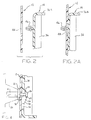
- FIGURES 2 and 2A are cross-sectional views taken on lines 2-2 of FIGURE 1 and respectively showing the lock plate in a position prior to installation on the auto body panel and after installation but in an elevated lamp removal position;
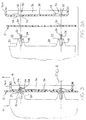
- FIGURES 3 and 3A are cross-sectional views taken on lines 3-3 of FIGURE 1 and respectively showing the components in assembled and disassembled relationship;
- FIGURE 4 is a greatly enlarged view of the circled portion of FIGURE 3 and showing the latch means on the lock plate; and
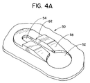
- FIGURE 4A is an isometric view showing the latch means on the lock plate.
- Referring more particularly to the drawings wherein the showings are for the purpose of illustrating a preferred embodiment of the invention, and not for the purpose of limiting same, FIGURE 1 best illustrates the overall arrangement of the subject invention. As noted earlier, the FIGURE 1 showing is a pictorial illustration of the major components of the system in an exploded, disassembled relationship. As illustrated in FIGURE 1, the overall system comprises the
headlamp assembly 10 arranged to be joined to abody panel 12 by alock plate 14. Theheadlamp assembly 10 is shown only generally and in phantom. It could obviously have a variety of shapes and configurations in keeping with the many shapes, sizes, and configurations of conventional headlamp assemblies. However, in the subject embodiment, theassembly 10 is provided with pins orstuds 16 which extend rearwardly from the rear wall ofassembly 10. Thepins 16 are preferably formed from a suitable metal such as steel and include ashank 18 which is adapted to be permanently molded or otherwise connected directly into the housing of thelamp assembly 10. In the subject embodiment, theshank 18 is molded into a raised or rearwardly extendingfoot portion 20 of the lamp assembly housing. - Preferably, the
pins 16 include ashoulder 22 which is in the nature of a radially extending flange that acts as a base or limit for the pin and engages with the outer top end ofpost 20. Extending axially outwardly from theflange 22 is anexterior shank 24 that terminates in a radially extending, enlargedhead 26. - The
headlamp assembly 10 is illustrated as being provided with three of the pins orstuds 16, however, the actual number and placement of these studs could vary from that shown. - Headlamp assembly is mounted to the
vehicle body panel 12 by having thestuds 16 extend throughopenings 30 formed throughbody panel 12. Theopenings 30 are preferably simple round openings sized slightly larger than the enlargedheads 26 to permit easy insertion of the heads. Although thebody panel 12 is shown as a simple sheet metal panel, it could be of other constructions and provided with suitable reinforcing and the like (not shown). - The lamp assembly is maintained in its mounted position on the auto body panel by the previously-mentioned
lock plate 14. Thelock plate 14 is best seen in FIGURES 1, 2, and 3 and generally comprises a molded plastic,U-shaped plate body 34 having the general configuration shown and provided with a continuous peripheral reinforcingflange 36 that extends completely about the exterior and interior of the U-shapedplate 34. As shown in FIGURES 3 and 3A, the top portion of theflange 36 extends rearwardly a slightly greater distance than the remaining portion to provide a handle or manually gripping portion 36a. - The
lock plate 14 is connected to theauto body panel 12 in a manner which maintains it in its operable position but allows it to move vertically between a first release position and a lowered second position which locks the lamp assembly to thebody panel 12. For this reason, the lock plate is provided with a plurality of outwardly extendingpins 40 that perform a locating and mounting function. Two of thepins 40 are shown in FIGURE 1. The pins are positioned to engage the elongated, vertically extendingopenings 44 formed in the body panel at locations corresponding to the locations of thepins 40 onplate 14. Thepins 40 could be of many types. The preferred form is best illustrated in FIGURES 2 and 2A and includes an arrow-shaped head with four radially resilient sections that can compress or collapse radially inwardly to permit insertion into thenarrower openings 44. After insertion, the arrow likehead 46 expands to hold theplate 14 firmly in position in thebody panel 12. The plate is, however, capable of being moved manually vertically relative to theslots 44. - As best seen in FIGURES 1, 3, and 3A, the
plate 14 is further provided with three keyhole-shaped openings 50 which are located onplate 30 at locations corresponding to the locations of the firstbody panel openings 30. Each of the key-holeshaped openings 50 includes acircular opening 52 and an elongated, upwardly extendingslot 54.Openings 52 are preferably at least as large asopenings 30 and thestud heads 26. Thus, when the lock plate is in its elevated position relative toslots 44, theopenings stud head 26 can be inserted therethrough. Thereafter, thelock plate 14 can be slid downwardly to the latched position shown in FIGURE 3. This causes the plate to engage behind thestud head 26 and firmly pull the lamp assembly into a mounted position where it is held by the presence of the lock plate. - As best shown in FIGURES 4 and 4A, together with FIGURE 3, the
lock plate 14 is provided with latch means to maintain it in the down locked position and to firmly bias the lamp assembly into engagement with thebody panel 12. As shown in FIGURES 3 and 4, the latch means comprise aramp section 58 which is located adjacent both sides of theslot section 54 ofopenings 50. Thisupward ramp section 58 leads to a raised flat section which includes ashoulder 62. The shoulder is positioned and arranged to engage about thehead 26 as shown in FIGURE 4 to lock theplate 14 in its lower second lock position. Only by manually deflecting the shoulder portion axially inwardly relative to head 26 ofpin 16 or by exerting a predetermined upward force on the lock plate is it possible to release the lock plate from the latched position. This, however, can be accomplished without the use of tools or any additional apparatus. - The invention has been described with reference to the preferred embodiment. Obviously, modifications and alterations will occur to others upon a reading and understanding of this specification. It is intended to include all such modifications and alterations insofar as they come within the scope of the appended claims or the equivalents thereof.
Claims (10)
- In a vehicle having a lamp mounted therein, a lamp mounting arrangement comprising:
a mounting support panel forming a part of the vehicle, a lamp assembly having a rear exterior wall with a plurality of mounting studs extending outwardly therefrom, the studs having an outer end portion with an enlarged head extending through aligned first openings in the support panel;
a lock plate connected to the mounting support panel on the side of the mounting support panel opposite the lamp assembly for sliding movement between a first position for preventing withdrawal of the mounting studs from the first openings in the mounting support plate and a second position for permitting withdrawal of the mounting studs from the first openings; and,
latch means for limiting undesired sliding movement of the lock plate in a direction toward the second position. - The lamp mounting arrangement as defined in claim 1 wherein the lock plate includes slotted portions which engage between the enlarged heads and the mounting support panel.
- The lamp mounting arrangement as defined in claim 2 wherein the latch means is associated with the slotted portions and engages an enlarged head on at least one mounting stud.
- The lamp mounting arrangement as defined in claim 3 wherein the latch means comprises a resilient shoulder adjacent the slotted portions.
- The lamp mounting arrangement as defined in claim 1 wherein the lock plate is connected to the mounting support panel by post elements which extend from the lock plate through second openings formed in the mounting support panel.
- The lamp mounting arrangement as defined in claim 5 wherein the lock plate is formed of plastics material and the post elements are formed integrally therewith.
- The lamp mounting arrangement as defined in claim 5 wherein the second openings are elongated slots sized to permit sliding movement of the lock plate between the first and second positions.
- The lamp mounting arrangement as defined in claim 5 wherein the post elements include resilient head portions that can be collapsed to permit selective insertion and removal of the post elements from the second openings.
- The lamp mounting arrangement as defined in claim 5 wherein the post elements include shanks that extend through the second openings and are retained therein by resilient head portions that are formed on the shanks, the second openings being sized to permit free sliding movement of the shank portions therein.
- In a vehicle having a mounting arrangement comprising:
a mounting support panel forming a part of the vehicle;
a lock plate connected to the mounting support panel; and
latch means for limiting undesired sliding movement of the lock plate.
Applications Claiming Priority (2)
| Application Number | Priority Date | Filing Date | Title |
|---|---|---|---|
| US08/126,269 US5420762A (en) | 1993-09-24 | 1993-09-24 | Automotive headlamp assembly fastening system |
| US126269 | 1993-09-24 |
Publications (2)
| Publication Number | Publication Date |
|---|---|
| EP0649773A1 true EP0649773A1 (en) | 1995-04-26 |
| EP0649773B1 EP0649773B1 (en) | 1998-07-29 |
Family
ID=22423916
Family Applications (1)
| Application Number | Title | Priority Date | Filing Date |
|---|---|---|---|
| EP94115013A Expired - Lifetime EP0649773B1 (en) | 1993-09-24 | 1994-09-23 | Automotive headlamp assembly fastening system |
Country Status (3)
| Country | Link |
|---|---|
| US (1) | US5420762A (en) |
| EP (1) | EP0649773B1 (en) |
| DE (1) | DE69412027T2 (en) |
Cited By (9)
| Publication number | Priority date | Publication date | Assignee | Title |
|---|---|---|---|---|
| FR2746728A1 (en) * | 1996-03-28 | 1997-10-03 | Valeo Vision | Motor vehicle signal or headlamp shell with clip fixing to mounting |
| EP0897173A2 (en) * | 1997-08-11 | 1999-02-17 | The Whitaker Corporation | Multiple lens component |
| FR2820378A1 (en) * | 2001-02-08 | 2002-08-09 | Faurecia Ind | VEHICLE OPTICAL BLOCK COMPRISING MEANS FOR ATTACHING IMPROVED SPOTLIGHTS |
| WO2003076229A1 (en) * | 2002-03-14 | 2003-09-18 | Nissan Motor Co.,Ltd. | Headlamp mounting structure of automobile |
| EP1398209A1 (en) * | 2002-09-12 | 2004-03-17 | Valeo Vision | Arrangement to fasten a lighting or signaling device on a support provided on a vehicle |
| EP1705060A1 (en) * | 2005-03-22 | 2006-09-27 | Valeo Vision | Hood for covering an opening of a lighting device housing |
| FR2908847A1 (en) * | 2006-11-20 | 2008-05-23 | Faurecia Bloc Avant | Left front wing flare assembly for motor vehicle, has stubs, whose bodies are terminated by enlarged heads, where stubs are penetrated and locked in retracted portions by relative displacement of flare and wing after insertion of heads |
| DE102010026218A1 (en) * | 2010-07-06 | 2012-01-12 | Gm Global Technology Operations Llc (N.D.Ges.D. Staates Delaware) | Attaching unit for attaching e.g. electronic functional element at windscreen of vehicle, has carrier formed with mounting hole that comprises elongated hole attached to borehole, where region limiting mounting hole is partially deformable |
| EP2072331B1 (en) * | 2007-12-20 | 2015-02-11 | Hella KGaA Hueck & Co. | Fixing device for a lighting unit and method of exchanging the bulb |
Families Citing this family (32)
| Publication number | Priority date | Publication date | Assignee | Title |
|---|---|---|---|---|
| JP3230948B2 (en) * | 1994-10-03 | 2001-11-19 | キヤノン株式会社 | Image forming device |
| US5595433A (en) * | 1995-08-28 | 1997-01-21 | Chrysler Corporation | Back light assembly |
| US5762310A (en) * | 1996-02-09 | 1998-06-09 | Schill; Francine E. | Infant seat support with a resting surface having an adjustable height |
| US6015313A (en) * | 1997-06-17 | 2000-01-18 | The Whitaker Corporation | Lamp assembly |
| US6142435A (en) * | 1999-06-18 | 2000-11-07 | Richco Inc. | Integral mounting base support for components |
| US6266250B1 (en) * | 2000-04-26 | 2001-07-24 | Multiplex Technology, Inc. | Electronics component mounting system |
| US20020117595A1 (en) | 2001-02-27 | 2002-08-29 | Didier Bierjon | Horizontally adjustable fixture attachment system |
| US20040011689A1 (en) * | 2002-07-18 | 2004-01-22 | Witold Bauer | Sterilization container filter system |
| US7083051B2 (en) * | 2002-11-15 | 2006-08-01 | Adc Telecommunications, Inc. | Cable management assembly, system and method |
| TWI253857B (en) * | 2005-02-23 | 2006-04-21 | Benq Corp | Flat panel display device |
| US7677400B2 (en) * | 2005-04-07 | 2010-03-16 | Adc Telecommunications, Inc. | Cable management assembly, system and method |
| TWI255895B (en) * | 2005-05-26 | 2006-06-01 | Au Optronics Corp | Backlight module and lamp holder thereof |
| US7669443B2 (en) * | 2005-09-19 | 2010-03-02 | Kevin Larue Varner | Universal mounting and locking device for tool storage containers and portable items |
| US7298951B2 (en) * | 2006-02-16 | 2007-11-20 | Adc Telecommunications, Inc. | Cable management device and method |
| US7764857B2 (en) * | 2006-08-25 | 2010-07-27 | Adc Telecommunications, Inc. | Cable management system with twist latch |
| US7369740B2 (en) * | 2006-08-25 | 2008-05-06 | Adc Telecommunications, Inc. | Cable management system with spring latch |
| US7647734B2 (en) * | 2007-05-21 | 2010-01-19 | Skidmore Owings & Merrill Llp | Seismic structural device |
| DE102008020082A1 (en) * | 2008-04-22 | 2009-10-29 | Dr. Ing. H.C. F. Porsche Aktiengesellschaft | Air guiding component and body stem of a motor vehicle |
| US20100050706A1 (en) * | 2008-09-03 | 2010-03-04 | Lucasey Manufacturing Company | Releasable security mount |
| US9388834B2 (en) * | 2011-09-08 | 2016-07-12 | Visor Frames, LLC | Rotating attachment device and method of use |
| CN103115297A (en) * | 2011-11-17 | 2013-05-22 | 富准精密工业(深圳)有限公司 | Lamp |
| US9014402B2 (en) * | 2012-05-16 | 2015-04-21 | Klover Products, Inc. | Acoustically isolated parabolic sound pickup assembly |
| US9206634B1 (en) * | 2013-03-15 | 2015-12-08 | Overhead Door Corporation | Counterbalance system for vertical acting doors |
| DE102013102835B4 (en) * | 2013-03-20 | 2022-12-29 | HELLA GmbH & Co. KGaA | lighting device |
| CN103569216A (en) * | 2013-10-30 | 2014-02-12 | 上海双杰科技有限公司 | Wheel house panel mounting structure |
| CN104676502B (en) * | 2013-11-26 | 2020-02-18 | 深圳市海洋王照明工程有限公司 | Lamp fitting |
| US9992569B2 (en) | 2014-05-30 | 2018-06-05 | Paul D. Terpstra | Camera-mountable acoustic collection assembly |
| CN107406041B (en) * | 2015-03-12 | 2020-11-03 | Trw汽车美国有限责任公司 | Mounting device for driver assistance system shell |
| JP6502878B2 (en) * | 2016-03-01 | 2019-04-17 | 株式会社スギノマシン | Hand stocker and hand |
| US11204050B2 (en) | 2018-03-29 | 2021-12-21 | Stance Healthcare Inc | Flexible bracket for joint structure assembly |
| DE102020104316B3 (en) * | 2020-02-19 | 2021-06-02 | Dr. Ing. H.C. F. Porsche Aktiengesellschaft | Device for attaching a light strip to a motor vehicle |
| TWI715465B (en) * | 2020-03-17 | 2021-01-01 | 技嘉科技股份有限公司 | Wall mount assembly |
Citations (5)
| Publication number | Priority date | Publication date | Assignee | Title |
|---|---|---|---|---|
| DE470472C (en) * | 1929-01-19 | Heinrich Beiker | Detachable fastening device for top material on the car body | |
| DE3617101A1 (en) * | 1986-05-21 | 1987-10-15 | Bayerische Motoren Werke Ag | Fastening of a sheet-like structural part on an underlying part |
| US5063481A (en) * | 1990-10-15 | 1991-11-05 | Eaton Corporation | Pivot assembly for vehicle headlight position adjustment |
| FR2662981A1 (en) * | 1990-06-08 | 1991-12-13 | Valeo Vision | DEVICE AND METHOD FOR THE AUTOMATIC MOUNTING OF SUPPORT EQUIPMENT, AND MORE PARTICULARLY A LIGHTING AND / OR SIGNALING DEVICE ON A MOTOR VEHICLE. |
| US5163746A (en) * | 1990-05-01 | 1992-11-17 | Textron Inc. | Assembly for headlamp adjustment |
Family Cites Families (9)
| Publication number | Priority date | Publication date | Assignee | Title |
|---|---|---|---|---|
| US2117756A (en) * | 1936-03-02 | 1938-05-17 | Kingston Products Corp | Electric lighting device |
| US2117759A (en) * | 1936-04-04 | 1938-05-17 | Kingston Products Corp | Electric lighting device |
| US2719750A (en) * | 1952-08-02 | 1955-10-04 | Carbodies Ltd | Mounting means for a pivoted automobile window |
| US3309644A (en) * | 1965-04-26 | 1967-03-14 | Clark Equipment Co | Electrical connector |
| US4012686A (en) * | 1971-03-18 | 1977-03-15 | Optotechnik, Gmbh | Power supply for illuminated instrument |
| US4550230A (en) * | 1982-10-18 | 1985-10-29 | International Jensen Incorporated | Speaker grille with snap-in fastener system |
| GB2181178A (en) * | 1985-10-04 | 1987-04-15 | Gen Motors France | A method of attaching a brake booster to a vehicle |
| JP3229968B2 (en) * | 1990-07-23 | 2001-11-19 | 株式会社パイオラックス | Mounting structure of lamp base for automobile |
| US5201579A (en) * | 1991-08-06 | 1993-04-13 | General Motors Corporation | Lamp housing mounting arrangement |
-
1993
- 1993-09-24 US US08/126,269 patent/US5420762A/en not_active Expired - Lifetime
-
1994
- 1994-09-23 EP EP94115013A patent/EP0649773B1/en not_active Expired - Lifetime
- 1994-09-23 DE DE69412027T patent/DE69412027T2/en not_active Expired - Fee Related
Patent Citations (5)
| Publication number | Priority date | Publication date | Assignee | Title |
|---|---|---|---|---|
| DE470472C (en) * | 1929-01-19 | Heinrich Beiker | Detachable fastening device for top material on the car body | |
| DE3617101A1 (en) * | 1986-05-21 | 1987-10-15 | Bayerische Motoren Werke Ag | Fastening of a sheet-like structural part on an underlying part |
| US5163746A (en) * | 1990-05-01 | 1992-11-17 | Textron Inc. | Assembly for headlamp adjustment |
| FR2662981A1 (en) * | 1990-06-08 | 1991-12-13 | Valeo Vision | DEVICE AND METHOD FOR THE AUTOMATIC MOUNTING OF SUPPORT EQUIPMENT, AND MORE PARTICULARLY A LIGHTING AND / OR SIGNALING DEVICE ON A MOTOR VEHICLE. |
| US5063481A (en) * | 1990-10-15 | 1991-11-05 | Eaton Corporation | Pivot assembly for vehicle headlight position adjustment |
Cited By (17)
| Publication number | Priority date | Publication date | Assignee | Title |
|---|---|---|---|---|
| ES2137841A1 (en) * | 1996-03-28 | 1999-12-16 | Valeo Vision | Motor vehicle signal or headlamp shell with clip fixing to mounting |
| FR2746728A1 (en) * | 1996-03-28 | 1997-10-03 | Valeo Vision | Motor vehicle signal or headlamp shell with clip fixing to mounting |
| EP0897173A2 (en) * | 1997-08-11 | 1999-02-17 | The Whitaker Corporation | Multiple lens component |
| EP0897173A3 (en) * | 1997-08-11 | 1999-12-29 | The Whitaker Corporation | Multiple lens component |
| FR2820378A1 (en) * | 2001-02-08 | 2002-08-09 | Faurecia Ind | VEHICLE OPTICAL BLOCK COMPRISING MEANS FOR ATTACHING IMPROVED SPOTLIGHTS |
| EP1231107A1 (en) * | 2001-02-08 | 2002-08-14 | Faurecia Industries | Headlamp unit for vehicle with improved headlamp fastening means |
| US6698914B2 (en) | 2001-02-08 | 2004-03-02 | Faurecia Industries | Optical unit for a vehicle, comprising improved headlamp fastening means |
| US6997585B2 (en) | 2002-03-14 | 2006-02-14 | Nissan Motor Co., Ltd. | Headlamp mounting structure for automobile |
| WO2003076229A1 (en) * | 2002-03-14 | 2003-09-18 | Nissan Motor Co.,Ltd. | Headlamp mounting structure of automobile |
| EP1398209A1 (en) * | 2002-09-12 | 2004-03-17 | Valeo Vision | Arrangement to fasten a lighting or signaling device on a support provided on a vehicle |
| FR2844500A1 (en) * | 2002-09-12 | 2004-03-19 | Valeo Vision | ARRANGEMENT FOR FIXING A LIGHTING OR SIGNALING DEVICE ON A SUPPORT PROVIDED ON A MOTOR VEHICLE |
| EP1705060A1 (en) * | 2005-03-22 | 2006-09-27 | Valeo Vision | Hood for covering an opening of a lighting device housing |
| FR2883630A1 (en) * | 2005-03-22 | 2006-09-29 | Valeo Vision Sa | LIGHTING DEVICE HOUSING OPENING DEVICE FOR MOTOR VEHICLE |
| US7581861B2 (en) | 2005-03-22 | 2009-09-01 | Valeo Vision | Device for closing off the opening in a lighting device housing for a motor vehicle |
| FR2908847A1 (en) * | 2006-11-20 | 2008-05-23 | Faurecia Bloc Avant | Left front wing flare assembly for motor vehicle, has stubs, whose bodies are terminated by enlarged heads, where stubs are penetrated and locked in retracted portions by relative displacement of flare and wing after insertion of heads |
| EP2072331B1 (en) * | 2007-12-20 | 2015-02-11 | Hella KGaA Hueck & Co. | Fixing device for a lighting unit and method of exchanging the bulb |
| DE102010026218A1 (en) * | 2010-07-06 | 2012-01-12 | Gm Global Technology Operations Llc (N.D.Ges.D. Staates Delaware) | Attaching unit for attaching e.g. electronic functional element at windscreen of vehicle, has carrier formed with mounting hole that comprises elongated hole attached to borehole, where region limiting mounting hole is partially deformable |
Also Published As
| Publication number | Publication date |
|---|---|
| US5420762A (en) | 1995-05-30 |
| DE69412027T2 (en) | 1999-04-01 |
| DE69412027D1 (en) | 1998-09-03 |
| EP0649773B1 (en) | 1998-07-29 |
Similar Documents
| Publication | Publication Date | Title |
|---|---|---|
| EP0649773B1 (en) | Automotive headlamp assembly fastening system | |
| EP1957323B1 (en) | Fastener | |
| EP0691230B1 (en) | Visor clip assembly and releasable fastener | |
| US5215332A (en) | Quick release seat belt anchor | |
| US4786119A (en) | Locking clip for securing a bolt holding panel members together | |
| US7318256B2 (en) | Resilient clip fastener | |
| EP1264743B1 (en) | A fastener stud for a snap-on mounting attachment | |
| US4874276A (en) | Fastener | |
| US20040136812A1 (en) | Fastener for curtain airbag | |
| AU2003200566B2 (en) | Self-locking rivet fastener | |
| US6176660B1 (en) | Releasable fastener with lateral stabilizing brace members and latch legs carrying fastener insertion guide | |
| US6747209B2 (en) | Clamp | |
| US5345658A (en) | Fastener for truck bed liner | |
| KR20010079749A (en) | Snap-in airbag module | |
| JP6869924B2 (en) | Stud lock | |
| KR100421112B1 (en) | Rectangular hole snap-in fastener | |
| JPH09226501A (en) | Occupant restriction device of automobile | |
| US7607807B2 (en) | Vehicular lamp and retainer assembly for interior applications | |
| EP0067965A1 (en) | Fastening arrangement including a wedge | |
| US6511115B2 (en) | Arrangement for rapid securing of an apparatus in an installation opening in a central console or the like of a motor vehicle | |
| AU2020104223A4 (en) | Mounting bracket for a vehicle recovery board | |
| JP3488752B2 (en) | Automotive headlamp assembly mounting device | |
| CN111664153A (en) | Rivet type fastener | |
| US6352441B2 (en) | Locking spring for a circuit board ejector | |
| JPH06343526A (en) | Fitting structure for drawer rail |
Legal Events
| Date | Code | Title | Description |
|---|---|---|---|
| PUAI | Public reference made under article 153(3) epc to a published international application that has entered the european phase |
Free format text: ORIGINAL CODE: 0009012 |
|
| AK | Designated contracting states |
Kind code of ref document: A1 Designated state(s): DE FR GB SE |
|
| 17P | Request for examination filed |
Effective date: 19951025 |
|
| 17Q | First examination report despatched |
Effective date: 19961030 |
|
| GRAG | Despatch of communication of intention to grant |
Free format text: ORIGINAL CODE: EPIDOS AGRA |
|
| GRAG | Despatch of communication of intention to grant |
Free format text: ORIGINAL CODE: EPIDOS AGRA |
|
| GRAH | Despatch of communication of intention to grant a patent |
Free format text: ORIGINAL CODE: EPIDOS IGRA |
|
| GRAH | Despatch of communication of intention to grant a patent |
Free format text: ORIGINAL CODE: EPIDOS IGRA |
|
| GRAA | (expected) grant |
Free format text: ORIGINAL CODE: 0009210 |
|
| AK | Designated contracting states |
Kind code of ref document: B1 Designated state(s): DE FR GB SE |
|
| REF | Corresponds to: |
Ref document number: 69412027 Country of ref document: DE Date of ref document: 19980903 |
|
| ET | Fr: translation filed | ||
| PLBE | No opposition filed within time limit |
Free format text: ORIGINAL CODE: 0009261 |
|
| STAA | Information on the status of an ep patent application or granted ep patent |
Free format text: STATUS: NO OPPOSITION FILED WITHIN TIME LIMIT |
|
| 26N | No opposition filed | ||
| PGFP | Annual fee paid to national office [announced via postgrant information from national office to epo] |
Ref country code: SE Payment date: 20000901 Year of fee payment: 7 |
|
| PG25 | Lapsed in a contracting state [announced via postgrant information from national office to epo] |
Ref country code: SE Free format text: LAPSE BECAUSE OF NON-PAYMENT OF DUE FEES Effective date: 20010924 |
|
| REG | Reference to a national code |
Ref country code: GB Ref legal event code: IF02 |
|
| EUG | Se: european patent has lapsed |
Ref document number: 94115013.8 |
|
| PGFP | Annual fee paid to national office [announced via postgrant information from national office to epo] |
Ref country code: FR Payment date: 20080904 Year of fee payment: 15 |
|
| PGFP | Annual fee paid to national office [announced via postgrant information from national office to epo] |
Ref country code: GB Payment date: 20080808 Year of fee payment: 15 |
|
| PGFP | Annual fee paid to national office [announced via postgrant information from national office to epo] |
Ref country code: DE Payment date: 20080930 Year of fee payment: 15 |
|
| GBPC | Gb: european patent ceased through non-payment of renewal fee |
Effective date: 20090923 |
|
| REG | Reference to a national code |
Ref country code: FR Ref legal event code: ST Effective date: 20100531 |
|
| PG25 | Lapsed in a contracting state [announced via postgrant information from national office to epo] |
Ref country code: FR Free format text: LAPSE BECAUSE OF NON-PAYMENT OF DUE FEES Effective date: 20090930 Ref country code: DE Free format text: LAPSE BECAUSE OF NON-PAYMENT OF DUE FEES Effective date: 20100401 |
|
| PG25 | Lapsed in a contracting state [announced via postgrant information from national office to epo] |
Ref country code: GB Free format text: LAPSE BECAUSE OF NON-PAYMENT OF DUE FEES Effective date: 20090923 |