EP0649348B1 - Segmented slot die for air spray of fibers - Google Patents
Segmented slot die for air spray of fibers Download PDFInfo
- Publication number
- EP0649348B1 EP0649348B1 EP93917034A EP93917034A EP0649348B1 EP 0649348 B1 EP0649348 B1 EP 0649348B1 EP 93917034 A EP93917034 A EP 93917034A EP 93917034 A EP93917034 A EP 93917034A EP 0649348 B1 EP0649348 B1 EP 0649348B1
- Authority
- EP
- European Patent Office
- Prior art keywords
- air
- slot
- coating material
- flow
- extrusion
- Prior art date
- Legal status (The legal status is an assumption and is not a legal conclusion. Google has not performed a legal analysis and makes no representation as to the accuracy of the status listed.)
- Expired - Lifetime
Links
- 239000000835 fiber Substances 0.000 title description 3
- 239000007921 spray Substances 0.000 title description 3
- 239000000463 material Substances 0.000 claims abstract description 67
- 239000000853 adhesive Substances 0.000 claims abstract description 35
- 230000001070 adhesive effect Effects 0.000 claims abstract description 35
- 238000000576 coating method Methods 0.000 claims description 97
- 239000011248 coating agent Substances 0.000 claims description 67
- 239000000758 substrate Substances 0.000 claims description 36
- 238000001125 extrusion Methods 0.000 claims description 31
- 238000000034 method Methods 0.000 claims description 13
- 230000008021 deposition Effects 0.000 claims description 6
- 230000000977 initiatory effect Effects 0.000 claims 1
- 239000012943 hotmelt Substances 0.000 description 21
- 239000004831 Hot glue Substances 0.000 description 20
- 238000003475 lamination Methods 0.000 description 5
- 239000011324 bead Substances 0.000 description 4
- 230000008901 benefit Effects 0.000 description 4
- 230000008569 process Effects 0.000 description 4
- 239000007787 solid Substances 0.000 description 4
- 230000002745 absorbent Effects 0.000 description 3
- 239000002250 absorbent Substances 0.000 description 3
- 230000003247 decreasing effect Effects 0.000 description 3
- 238000004519 manufacturing process Methods 0.000 description 3
- 239000002245 particle Substances 0.000 description 3
- 239000004033 plastic Substances 0.000 description 3
- 238000007664 blowing Methods 0.000 description 2
- 230000000694 effects Effects 0.000 description 2
- 239000003292 glue Substances 0.000 description 2
- 238000005507 spraying Methods 0.000 description 2
- 230000005540 biological transmission Effects 0.000 description 1
- 230000008859 change Effects 0.000 description 1
- 238000010030 laminating Methods 0.000 description 1
- 230000008018 melting Effects 0.000 description 1
- 238000002844 melting Methods 0.000 description 1
- 230000004048 modification Effects 0.000 description 1
- 238000012986 modification Methods 0.000 description 1
- 239000003973 paint Substances 0.000 description 1
- 238000005086 pumping Methods 0.000 description 1
- 230000009467 reduction Effects 0.000 description 1
- 229920001169 thermoplastic Polymers 0.000 description 1
- 239000004416 thermosoftening plastic Substances 0.000 description 1
Images


Classifications
-
- B—PERFORMING OPERATIONS; TRANSPORTING
- B05—SPRAYING OR ATOMISING IN GENERAL; APPLYING FLUENT MATERIALS TO SURFACES, IN GENERAL
- B05D—PROCESSES FOR APPLYING FLUENT MATERIALS TO SURFACES, IN GENERAL
- B05D1/00—Processes for applying liquids or other fluent materials
- B05D1/02—Processes for applying liquids or other fluent materials performed by spraying
- B05D1/12—Applying particulate materials
-
- B—PERFORMING OPERATIONS; TRANSPORTING
- B05—SPRAYING OR ATOMISING IN GENERAL; APPLYING FLUENT MATERIALS TO SURFACES, IN GENERAL
- B05C—APPARATUS FOR APPLYING FLUENT MATERIALS TO SURFACES, IN GENERAL
- B05C5/00—Apparatus in which liquid or other fluent material is projected, poured or allowed to flow on to the surface of the work
- B05C5/02—Apparatus in which liquid or other fluent material is projected, poured or allowed to flow on to the surface of the work the liquid or other fluent material being discharged through an outlet orifice by pressure, e.g. from an outlet device in contact or almost in contact, with the work
- B05C5/0254—Coating heads with slot-shaped outlet
-
- B—PERFORMING OPERATIONS; TRANSPORTING
- B05—SPRAYING OR ATOMISING IN GENERAL; APPLYING FLUENT MATERIALS TO SURFACES, IN GENERAL
- B05D—PROCESSES FOR APPLYING FLUENT MATERIALS TO SURFACES, IN GENERAL
- B05D5/00—Processes for applying liquids or other fluent materials to surfaces to obtain special surface effects, finishes or structures
- B05D5/10—Processes for applying liquids or other fluent materials to surfaces to obtain special surface effects, finishes or structures to obtain an adhesive surface
-
- D—TEXTILES; PAPER
- D04—BRAIDING; LACE-MAKING; KNITTING; TRIMMINGS; NON-WOVEN FABRICS
- D04H—MAKING TEXTILE FABRICS, e.g. FROM FIBRES OR FILAMENTARY MATERIAL; FABRICS MADE BY SUCH PROCESSES OR APPARATUS, e.g. FELTS, NON-WOVEN FABRICS; COTTON-WOOL; WADDING ; NON-WOVEN FABRICS FROM STAPLE FIBRES, FILAMENTS OR YARNS, BONDED WITH AT LEAST ONE WEB-LIKE MATERIAL DURING THEIR CONSOLIDATION
- D04H1/00—Non-woven fabrics formed wholly or mainly of staple fibres or like relatively short fibres
- D04H1/40—Non-woven fabrics formed wholly or mainly of staple fibres or like relatively short fibres from fleeces or layers composed of fibres without existing or potential cohesive properties
- D04H1/54—Non-woven fabrics formed wholly or mainly of staple fibres or like relatively short fibres from fleeces or layers composed of fibres without existing or potential cohesive properties by welding together the fibres, e.g. by partially melting or dissolving
- D04H1/56—Non-woven fabrics formed wholly or mainly of staple fibres or like relatively short fibres from fleeces or layers composed of fibres without existing or potential cohesive properties by welding together the fibres, e.g. by partially melting or dissolving in association with fibre formation, e.g. immediately following extrusion of staple fibres
-
- D—TEXTILES; PAPER
- D04—BRAIDING; LACE-MAKING; KNITTING; TRIMMINGS; NON-WOVEN FABRICS
- D04H—MAKING TEXTILE FABRICS, e.g. FROM FIBRES OR FILAMENTARY MATERIAL; FABRICS MADE BY SUCH PROCESSES OR APPARATUS, e.g. FELTS, NON-WOVEN FABRICS; COTTON-WOOL; WADDING ; NON-WOVEN FABRICS FROM STAPLE FIBRES, FILAMENTS OR YARNS, BONDED WITH AT LEAST ONE WEB-LIKE MATERIAL DURING THEIR CONSOLIDATION
- D04H3/00—Non-woven fabrics formed wholly or mainly of yarns or like filamentary material of substantial length
- D04H3/08—Non-woven fabrics formed wholly or mainly of yarns or like filamentary material of substantial length characterised by the method of strengthening or consolidating
- D04H3/16—Non-woven fabrics formed wholly or mainly of yarns or like filamentary material of substantial length characterised by the method of strengthening or consolidating with bonds between thermoplastic filaments produced in association with filament formation, e.g. immediately following extrusion
-
- D—TEXTILES; PAPER
- D06—TREATMENT OF TEXTILES OR THE LIKE; LAUNDERING; FLEXIBLE MATERIALS NOT OTHERWISE PROVIDED FOR
- D06N—WALL, FLOOR, OR LIKE COVERING MATERIALS, e.g. LINOLEUM, OILCLOTH, ARTIFICIAL LEATHER, ROOFING FELT, CONSISTING OF A FIBROUS WEB COATED WITH A LAYER OF MACROMOLECULAR MATERIAL; FLEXIBLE SHEET MATERIAL NOT OTHERWISE PROVIDED FOR
- D06N3/00—Artificial leather, oilcloth or other material obtained by covering fibrous webs with macromolecular material, e.g. resins, rubber or derivatives thereof
- D06N3/0086—Artificial leather, oilcloth or other material obtained by covering fibrous webs with macromolecular material, e.g. resins, rubber or derivatives thereof characterised by the application technique
- D06N3/0088—Artificial leather, oilcloth or other material obtained by covering fibrous webs with macromolecular material, e.g. resins, rubber or derivatives thereof characterised by the application technique by directly applying the resin
- D06N3/009—Artificial leather, oilcloth or other material obtained by covering fibrous webs with macromolecular material, e.g. resins, rubber or derivatives thereof characterised by the application technique by directly applying the resin by spraying components on the web
-
- Y—GENERAL TAGGING OF NEW TECHNOLOGICAL DEVELOPMENTS; GENERAL TAGGING OF CROSS-SECTIONAL TECHNOLOGIES SPANNING OVER SEVERAL SECTIONS OF THE IPC; TECHNICAL SUBJECTS COVERED BY FORMER USPC CROSS-REFERENCE ART COLLECTIONS [XRACs] AND DIGESTS
- Y10—TECHNICAL SUBJECTS COVERED BY FORMER USPC
- Y10T—TECHNICAL SUBJECTS COVERED BY FORMER US CLASSIFICATION
- Y10T156/00—Adhesive bonding and miscellaneous chemical manufacture
- Y10T156/17—Surface bonding means and/or assemblymeans with work feeding or handling means
- Y10T156/1798—Surface bonding means and/or assemblymeans with work feeding or handling means with liquid adhesive or adhesive activator applying means
Definitions
- This invention relates to the application of fibrous coatings to substrates and more particularly to the application to substrates of discrete, uniform fibrous adhesive coatings having sharp, square cut-on and cut-off edges.
- Such fibrous applications have in the past been applied in parallel fine lines, in swirl patterns or in random fibrous fashion by means of a melt-blown slot die apparatus such as disclosed in US-A-4,720,252.
- a melt-blown slot die apparatus such as disclosed in US-A-4,720,252.
- Such apparatus provides a non-woven fibrous web in low basis weights and is stated to reduce clogging due to the use of a slot die as opposed to a plurality of small opening nozzles for each fibrous component. Small particles are said to pass the slot die, which might otherwise clog a single fiber nozzle orifice.
- the slot thickness must be held at a narrow distance, which still may block slightly larger particles, resulting in clogging.
- the extruded web tends to draw in or neck-in at the edges. This produces a "rail roading" effect in the deposited web, i.e. thickened edges and thinner center portions. While the air blowing on the web tends to reduce this effect, it can still be pronounced, and is undesirable.
- melt blowing apparatus is generally used in the production of non-woven webs and not in adhesive coatings in lamination.
- curtain coaters do not generally produce good cut-on, cut-off edges and are subject to neck-in.
- Contact coaters present the inherent disadvantage of wear and substrate index and tension tolerances.
- the spray, fine line and spiral pattern applicators do not generally produce highly defined square edge cut-on and cut-off coating edges in a uniform broad coating, as are desired in a number of applications.
- a further objective of the invention has been to provide an improved slot die for the spraying of uniform low basis weight, fibrous adhesive coatings yet with minimal clogging compared with prior slot die apparatus.
- Another objective of this invention has been to provide improved methods and apparatus for intermittent non-contact application of fibrous thermoplastic coating material, having sharp, square, side, leading and trailing edges, to discrete, predetermined areas.
- a preferred embodiment of the invention includes a slot nozzle, elongated air channels on each side of the slot nozzle for impinging a flow of air on each side of a curtain of coating material extruding from the slot nozzle, and a segmented or comb-like shim in the die slot having a plurality of elongated slots through which adhesive material moves.
- the adhesive Upon emerging from the die, the adhesive merges and is blown by the air onto a uniform fibrous web for coating an underlying substrate.
- Means are provided for controlling the supply of material to the slot nozzle and the supply of air to the air channels so that each can be initiated and stopped at predetermined intervals to produce sharp, square leading and trailing edges in the deposited coatings.
- the invention produces uniform, solid or fibrous, wide or broad coatings having sharp side edges and sharp, square, leading and trailing edges coordinated with a predetermined underlying substrate area and applied in a non-contacting application process.
- Fig. 1 illustrates various features of a die means 30 and air and hot melt adhesive controls according to the invention.
- the die means 30 comprises two die halves 31, 32, and two air blocks 33, 34.
- Each die block 31, 32 includes a downwardly depending projection 35, 36.
- the die halves 31, 32 define between them an extrusion slot 37.
- Slot 37 is defined by the face 38 of the die half 31 and the face 39 of the die half 32. Face 38 is juxtaposed with respect to the face 39, as shown.
- the extrusion slot 37 terminates at an elongated slot nozzle or extrusion outlet 40. As noted in the Figures, the air blocks extend below the outlet 40 to provide a degree of protection from mechanical damage.
- Die half 32 includes a hot melt passageway 41 for receiving hot melt adhesive and conducting the hot melt adhesive to a "coat hanger" portion 42 of the die half 32, details of which are perhaps better seen in Fig. 4.
- a slotted or segmented shim 45 is located between the juxtaposed surfaces 38 and 39 of the die halves 31 and 32.
- the shim 45 has a plurality of elongated projections 46, defining between them a plurality of elongated channels or slots 47.
- Each of the projections has a downstream tapered end portion 48, having a preferably sharp tip 49 which is preferably flush with the lower edge 50 of the shim, and flush with the elongated slot nozzle extrusion outlet 40 (Fig. 1). Tips 49 could be disposed just internally of outlet 40.
- Fig. 1 only the top portion 51 of the shim 45 is shown, for the purpose of clarity. Alternatively, an open shim can be used.
- a further alternate shim 45 is shown in Fig. 6 A. Shim 45 a has tips 52 which extend beyond outlet 40 preferably about 0.005 - 0.008 cm (two to three thousandths of an inch).
- Fig. 6A illustrates an alternative shim wherein the tips 52 are tapered to a point, extending slightly beyond shim edge 50, opposed to flush tips 49 of Fig. 6. Tips 52 extend in the embodiment preferably 0.005 - 0.008 cm (two or three thousandths of an inch) beyond the slot nozzle extrusion outlet 40. Otherwise, this shim is the same as that of Fig. 6.
- the tips of the projections 46 are preferably sharply pointed, although they could be blunted, and the tips extend to a position proximate outlet 40.
- each of the upper die halves 31, 32 is provided with an air passageway 55, 56, extending from an upper surface of the die to a lower respective surface 57, 58.
- Each die half 31, 32 also includes an inclined surface 59, 60, depending from the surfaces 57 and 58, respectively.
- the inclined surfaces 59 and 60 define one part of an air passage, or air slot 61 and 62, as will be described.
- each of them include an inclined surface 63 and 64, respectively, which define the other side of the air slots 61 and 62 with the juxtaposed respective surfaces 59, 60, all as shown in Fig. 1.
- Each of the air blocks 33 and 34 include an upper surface 65, 66 juxtaposed to the respective lower surfaces 57 and 58 of the die halves 31, 32.
- An elongated air plenum 67, 68 is formed in each of the air blocks 33, 34.
- the plenums 67, 68 are also seen in Fig. 4.
- Respective air passages 69 and 70 are formed in the respective air blocks 33 and 34 and extend from the respective surfaces 65 and 66 to a lower portion 71, 72 of the respective plenums 67, 68.
- Each of the plenums 67, 68 are primarily defined in the air blocks 33 and 34. However, when the die means 30 are assembled, the top area of each of the respective plenums 67, 68 are defined respectively by the lower surfaces 57 and 58 of the die halves 31, 32.
- air can be introduced to passageway 56 in the die half 32 and from there it can move into the air passageway 70 and into the lower portion of the plenum 68. From the plenum 68, pressurized air is directed through the air passage 74 into the air slot 62 of the air block 34.
- a controller 75 is operationally connected to valves V-1 and V-2, as shown, for controlling the introduction of heated, pressurized air to the passages 55 and 56, respectively, in order to pressurize those passages and the downstream air passages as previously described, with air.
- the controller 75 is operationally interconnected to a hot melt control valve 76 for controlling the supply of coating material, such as hot melt adhesive, to the hot melt adhesive passage 41 and to the internal coat hanger area 42 of the die means 30.
- coating material such as hot melt adhesive
- the PC-10 pattern controller 75 is operational to initiate and to stop the generation of air into passages 55 and 56, either simultaneously or independently, and also to initiate and to stop the hot melt flowing through valve 76 so as to intermittently provide coating material to the passageway 41 independently and at pre-selected times with respect to the provision of pressurized heated air to the passages 55 and 56, all in a manner as will be described.
- the air slots 61 and 62 are oriented on an angle with respect to the elongation of the extrusion slot 37. Accordingly, when coating material is extruded through the slot 37 and outwardly of the extrusion outlet 40, air moving through the air slots 61 and 62 is impinged on the material before that material engages or is deposited on an underlying substrate which is presented for coating.
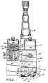
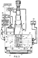
- Figs. 2 and 3 there is shown more of the overall extrusion apparatus according to the invention.
- the die means 30 is interconnected with air valves V-1, V-2 and hot melt valve 76, each of which is interconnected with an extrusion body 80 which operationally interconnects the air and hot melt valves with the die means 30.
- valve V-2 For clarity, a portion of the air valve V-2 is shown in partial cross section in Fig. 2. Since the valves V-1 and V-2 are identical, only valve V-2 will be described. Such air valves are manufactured and distributed by The Nordson Corporation through Nordson Engineering of Luneberg, Germany, under part no. 265701. Any other suitable valve can be used.
- Valve V-2 comprises a valve body 82 defining a valve chamber 83 and a control chamber 84, the two chambers being separated by the diaphragm 85.
- An extension 86 having a bore 87 extending therethrough depends from the valve body 82 and extends into the bore 88 of extrusion body 80 to form an annular chamber 89 therewith.
- Chamber 89 is interconnected with an annular passageway 90 in the valve body 82, which interconnects with the chamber 83.
- An annular chamber 91 is also defined in the valve body 82 and interconnects with the chamber 83.
- the air valve V-1 is operable to selectively supply air to the air passage 93 in the extrusion body 80 and from there to the air passage 55 in the upper die half 31. Air moves through that passageway 55 into the plenum 67 and from there to the air slot 61.
- the hot melt valve 76 can be any suitable hot melt valve which can be selectively controlled to initiate and to cut off the flow of coating material, such as hot melt adhesive, to the die means 30.
- One such suitable valve is balanced valve model no. EP51 produced by The Nordson Corporation of Westlake, Ohio. Such valve minimizes significant change in pressures when the valve is switched between its opened and closed positions.
- the valve 76 has a stem 96 seated over a port 97. When control air is supplied to an inlet 98, the stem 96 is lifted to permit hot melt adhesive in a chamber 99 to flow through the port 97 and into the hot melt passageway 41 of the upper die half 32. Hot melt adhesive is introduced into the chamber 99 through hot melt inlet 100.
- a hot melt outlet 101 is also interconnected with the chamber 99 to receive pressurized hot melt adhesive when the stem 96 is seated on port 97.
- Any suitable apparatus can be utilized for melting and pumping hot melt adhesive to the valve 76. Such apparatus is shown diagrammatically at 102. While any suitable apparatus could be utilized, one particular form of apparatus which is suitable is the model HM640 applicator, manufactured by The Nordson Corporation of Westlake, Ohio.
- Fig. 3 illustrates diagrammatically the various control inputs to the valves 76 and V-1.
- the controller 75 is interconnected to a control air supply 105 for supplying control air to the valves V-1 and V-2.
- a pressurized air source 106 is interconnected to an air heater 107 which supplies process air to the valves V-1 and V-2 for transmission to the respective air slots 61, 62, as described above.
- controller 75 is also interconnected to the control air supply for supplying control air through closed and opened solenoid control valves (shown in Fig. 3) to open and close the hot melt valve 76.
- plenums 67 and 68 in the air blocks 33, 34 communicate with the lower surfaces 73A and 74A, respectively, of the air passages 73 and 74 as previously described, and air emanating from the upper portion of the plenums 67 and 68 moves through the passageways 73 and 74 and then downwardly through the respective air slots 61, 62.
- coat hanger dies are known in general.
- one coat hanger-type die for handling hot melt adhesive is disclosed in US-A-4,687,137, expressly incorporated herein by reference. The difference in that structure is that it serves to provide a plurality of discrete beads, and not a continuous web of solid or fibrous adhesive as noted herein. While such a die could be used herein, nevertheless, the present die means 30 incorporates a "coat hanger" portion 42 having an arcuate slot or groove of increasingly shallow dimension 110 communicating with an incline surface 111.
- Surface 111 is inclined such that its lower portion, where it meets bottom surface 112, is closer to the plane of the face 39 than is the upper portion. It will also be appreciated that slot 110 is of decreasing depth as its distance from port 113 continues until it flows unbroken in surface 111.
- the arcuate slot 110 of decreasing depth is fed by the hot melt port 113, which is interconnected to the hot melt passage 41. In use, when hot melt is supplied at pressure to the passage 41, it exudes through the port 113 into the arcuate slot 110 and from there flows over the surface 111 and spreads out throughout the relieved coat hanger shaped portion 42 of the die face 39 and the side of the shim 45 which is juxtaposed to the face 39 of the die half 32.
- the slots 47 of shim 45 have upper ends which communicate with the lower portion of the coat hanger die area 42, just above the surface 112 thereof, so that hot melt adhesive or other coating material can flow into the slots 47 and then downwardly to the extrusion outlet 40.
- the coating material is spread throughout the coat hanger portion 42 and across each of the upper ends of the slots 47 of the shim 45 at significantly equal pressures, so that coating material can move through the extrusion slot 37 within the slots 47 of the shim 45 at relatively equal pressures.
- the width of the slots 47 between the projections 46 is preferably about twice the thickness of the shim 45.
- the thickness of one shim 45 may be about .01 cm (.004") while the slot width, i.e. from one projection 46 across to the next projection 46, is about .02 cm (.008").
- the shim thickness is about .02 cm (.008") while the segmented slot width between juxtaposed projections is about .04 cm (.016").
- the overall slot thickness between die faces 38, 39 can be doubled while the die still produces the same basis weight coating as a prior slot die where the die slot is not segmented, as in this invention.
- the present invention can obtain the same basis weight coating with a slot thickness of .01 cm (.004"), or doubled.
- the slot die according to the invention could pass a potentially clogging particle of .008 cm (.003") while the prior continuous slot die would not (for the same basis weight coating to be produced).
- the ratio of the slot width to the shim thickness is preferably about 2 to 1, this ratio can be varied to produce varying coating thicknesses.
- width and thickness parameters of the shims 45, 45a and their components can widely vary.
- the parameters may vary due to the basis weight of coating per square meter desired, the cohesiveness desired, the coating material viscosity or other factors.
- the surface 112 from face 39 back to surface 111 is about .05 cm (.020") wide.
- the tops of slots 47 are about .127 cm (.050") when the shim is operably disposed between faces 38, 39.
- the groove 110 at its deepest depth from face 39 is about .318 cm (.125") from face 39.
- the surface 111 at its top area is about .159 cm (1/16") deep from face 111 and about .05 cm (.020”) back from surface 39 at its bottom.
- the coat hanger width across face 39 is about 38 mm.
- the coating material may be precisely delivered to the heads or nozzles by one or more material metering means such as metering gear pumps.
- a single pump could feed a manifold for all the heads or nozzles or a separate metering gear pump could be used for each head or nozzle, or for a group of nozzles of less than all nozzles.
- This precise delivery permits accuracy in the material delivery so that accurate basis weight coatings can be provided for varying substrate speeds, for example.
- Any suitable form of metering feeds can be utilized.
- US-A-4,983,109 and US-A-4,891,249 expressly incorporated herein by reference, disclose metering means for hot melt adhesives.
- the apparatus is capable of impinging hot air from the slots 61 and 62 on each side of the coating material exuding from the extrusion outlet 40.
- the impinging air engages and shreds the emerging expanse of coating material into discrete micro-denier fibers.
- Edge control is uniform and the density of the pattern can range from 25% open or fibrous to 0% open, i.e. a non-porous film.
- the parameters are selected depending on the application to which the coatings are to be applied.
- the controller 75 is operational to start and stop the application of air to the extruded coating material at different times and/or intervals compared to the starting and stopping of the delivery of hot melt adhesive to the extrusion outlet 40.
- the flow of air through the slots 61, 62 is started a short time prior to the time when the valve 76 is operated to initiate the delivery of coating material into the slot 37 and out through the outlet 40.
- the air is continued for the coating deposition.
- the valve 76 is first operated to cease the extrusion of coating material through the outlet 40.
- the flow of air through the slot 61 and 62 is stopped. While the amount of delay in such an operation will vary, depending upon the properties of the hot melt, such time period generally will preferably be on the order of micro seconds.
- One example would be, for example, 1700 micro seconds between the start up of the air and the start up of the extrusion of the hot melt material, and 2100 micro seconds between the stopping of the hot melt material and the stopping of the air. Continuation of the air flow much beyond this time might serve to pull off remaining hot melt adhesive at the extrusion outlet and cause stringing of the deposited coating.
- the invention contemplates the selective applications of air flow through either slot 61 or 62 individually or together during the deposition period, particularly to more accurately define the initial and ending contact position of the deposited coating on the substrate.
- One such mode of operation is illustrated in Fig. 5, where the apparatus is utilized, for example, to apply a discrete coating to the spine of a book so that a cover can be applied or laminated thereto.
- a book having a spine with no adhesive thereon is shown at the left hand side of the figure at position B-1.
- air flow has been initiated through slot 61 but there is no coating material being extruded through the slot 37 and no air flow has started through the air slot 62.
- the hot melt flow has started and that it is impinged by air flowing through slot 61. Since the air flowing through slot 61 moves downwardly in a general right to left direction as shown in Fig. 5, it will be appreciated that the coating material does not string down the side of the book pages but is applied directly to the edge of the spine of the book with no stringing.
- the lag air is started first and stopped first and the lead air, that is, with respect to the machine direction of the application as shown in Fig. 5, is started after the extrusion of the coating material and stopped after the coating material extrusion has ceased.
- the air angling onto the coating material does not blow it in strings over the edges of the book, as would be undesirable and yet the cut-off and cut-on edges of the coating material are maintained in sharp, square fashion on the spine of the book.
- Fig. 8 illustrates the application of discrete fibrous coatings 10 to plastic web 11.
- the coatings have sharp, square leading and trailing edges 12 and 13 with no stringing.
- the low basis weight coatings when used for this application provide the additional advantage of cost reduction.
- Substrate material is saved since its thickness can be reduced by virtue of the lower weight coatings which do not have as much tendency to burn through the substrates when applied. Accordingly, the substrates can be thinner and material saved.
- the invention is believed useful with a wide range of coating materials of different viscosities, as shown by the following two examples.
- This adhesive had the following viscosities at the following temperatures:
- Operating temperature was at 180 degrees C. With a0.1 millimeter thick shim in the head, the supply pressure was 20 BAR, the return pressure of the adhesive was 21 BAR, and the air pressure was 1.5 BAR. The air was turned on 2 millimeters of substrate travel before the adhesive and turned off 2 millimeters of substrate travel after the adhesive. Substrate line speed is about 150 meters/minute. This corresponds to the delay times of about 800 micro seconds. At these settings, the cut-on and cut-off were square and sharp and a coating weight was produced of 5 grams per square meter of uniform thickness.
- This adhesive had the following viscosities:
- Operating temperature was 149 degrees C (300 degrees F).
- Coating weight was 15 grams per square meter. Cut-on and cut-off were square and sharp with no stringing.
- the hot melt supply pressure and return pressure be maintained in a relationship, such that the differences of the two pressures are not more than 1 BAR.
- a minimum flow rate is required to produce a uniform pattern with square and sharp cut-ons and cut-offs.
- a minimum flow rate is required to produce a uniform pattern with square and sharp cut-ons and cut-offs.
- a 38 millimeter wide pattern it is possible to get down to at least 1 gram per square meter of coating weight at approximately 350 meters per minute of line speed.
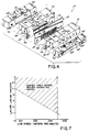
- the graph in Fig. 7 illustrates coating weights which have been obtained with a 38 millimeter wide pattern deposited on a substrate moving at about from 70 meters per minute to about 350 meters per minute, with the shaded area of the graph (Fig. 7) illustrating the proven operating ranges.
- coatings are produced in varying weights. Such coatings can be varied from 0% open or impervious to about 25% open or porous.
- the hot melt might be started at 2 mm of substrate movement after air start up, and the air flow stopped at 5 mm of substrate movement beyond extrusion shut off, for substrate speeds of about 70 meters/minute.
- the particular coating pattern produced by the apparatus and methods described above can either be porous or impervious and that the coating patterns are preferably produced in a discrete fashion on discrete substrates, for example, with good, square, sharp cut-on and cut-off and no stringing for the leading or trailing edges of the pattern, while at the same time, the sides of the pattern deposited are also parallel and sharp.
- the invention provides for intermittent non-contact coating operation with sharp, square-edged patterns and no stringing for a variety of applications, including lamination of the substrate to which the patterns are applied to some other substrate or component.
Landscapes
- Engineering & Computer Science (AREA)
- Textile Engineering (AREA)
- Coating Apparatus (AREA)
- Application Of Or Painting With Fluid Materials (AREA)
- Nozzles (AREA)
- Spinning Methods And Devices For Manufacturing Artificial Fibers (AREA)
Abstract
Description
- This invention relates to the application of fibrous coatings to substrates and more particularly to the application to substrates of discrete, uniform fibrous adhesive coatings having sharp, square cut-on and cut-off edges.
- Many industrial manufacturing processes require the application of fibrous adhesive coatings to substrates. For example, in the application of non-woven absorbent pads to impervious plastic web substrates, an application of fibrous adhesive is used to bond the two substrates together.
- Such fibrous applications have in the past been applied in parallel fine lines, in swirl patterns or in random fibrous fashion by means of a melt-blown slot die apparatus such as disclosed in US-A-4,720,252. Such apparatus provides a non-woven fibrous web in low basis weights and is stated to reduce clogging due to the use of a slot die as opposed to a plurality of small opening nozzles for each fibrous component. Small particles are said to pass the slot die, which might otherwise clog a single fiber nozzle orifice.
- When such dies are used to produce low basis weight coatings, the slot thickness must be held at a narrow distance, which still may block slightly larger particles, resulting in clogging. Also, when adhesive is extruded through the slot, the extruded web tends to draw in or neck-in at the edges. This produces a "rail roading" effect in the deposited web, i.e. thickened edges and thinner center portions. While the air blowing on the web tends to reduce this effect, it can still be pronounced, and is undesirable.
- Moreover, such melt blowing apparatus is generally used in the production of non-woven webs and not in adhesive coatings in lamination.
- In the production of discrete coatings and adhesives for lamination of discrete substrate areas, for example, it is desirable to obtain broad, uniform fibrous coatings in a non-contact application process with sharp, square, cut-on and cut-off edges with no stringing of material. None of the processes currently known are entirely suitable for this application.
- Many various devices have been used to apply adhesives for lamination, including curtain coaters, contact coaters, spray coaters, and, more recently, fine line or spiral pattern application devices. Curtain coaters do not generally produce good cut-on, cut-off edges and are subject to neck-in. Contact coaters present the inherent disadvantage of wear and substrate index and tension tolerances. The spray, fine line and spiral pattern applicators do not generally produce highly defined square edge cut-on and cut-off coating edges in a uniform broad coating, as are desired in a number of applications.
- Other devices have been used to apply hot melt adhesives. International Application No. WO-A-90/03847 discloses a round orifice nozzle through which a bead of hot melt adhesive is extruded and is atomized by surrounding air jets. There is no elongated air slot. International Application No. WO-A-89/00459 discloses a device for extruding a plurality of hot melt beads carried to a substrate separately. There is no air application and the beads are not merged prior to deposition.
- Accordingly, it has been one objective of the invention to provide an improved slot die apparatus for the air spraying of fibrous adhesive coatings.
- A further objective of the invention has been to provide an improved slot die for the spraying of uniform low basis weight, fibrous adhesive coatings yet with minimal clogging compared with prior slot die apparatus.
- It has been a further objective of this invention to produce improved broad, uniform, fibrous hot melt adhesive coatings with sharp side edges and sharp, square leading and trailing edges on intermittently presented discrete substrate areas.
- Another objective of this invention has been to provide improved methods and apparatus for intermittent non-contact application of fibrous thermoplastic coating material, having sharp, square, side, leading and trailing edges, to discrete, predetermined areas.
- To these ends the apparatus according to the invention comprises the features of
claim 1 and the method according to the invention comprises the features at claim 7. A preferred embodiment of the invention includes a slot nozzle, elongated air channels on each side of the slot nozzle for impinging a flow of air on each side of a curtain of coating material extruding from the slot nozzle, and a segmented or comb-like shim in the die slot having a plurality of elongated slots through which adhesive material moves. Upon emerging from the die, the adhesive merges and is blown by the air onto a uniform fibrous web for coating an underlying substrate. Means are provided for controlling the supply of material to the slot nozzle and the supply of air to the air channels so that each can be initiated and stopped at predetermined intervals to produce sharp, square leading and trailing edges in the deposited coatings. - The invention produces uniform, solid or fibrous, wide or broad coatings having sharp side edges and sharp, square, leading and trailing edges coordinated with a predetermined underlying substrate area and applied in a non-contacting application process.
- These and other objectives and advantages will become readily apparent from the following detailed description of a preferred embodiment of the invention and from the drawings in which:
- Fig. 1 is a diagrammatic side view in partial cross-section illustrating apparatus according to the invention;
- Fig. 2 is an elevational side view in partial cross section of a slot nozzle coater according to the invention;
- Fig. 3 is an elevational front view in partial cross-section of the apparatus of Fig. 2, illustrating diagrammatically control and flow features of the invention;
- Fig. 4 is an exploded view of the slot nozzle die of Fig. 2, showing the segmented shim of the invention;
- Fig. 5 is a diagrammatic view illustrating use of one embodiment of the invention in a book binding application;
- Fig. 6 is a front view of the slotted or segmented shim used in the slot nozzle die of the invention;
- Fig. 6A is a front view of an alternate shim;
- Fig. 7 is a graph illustrating coating weight applied v. substrate line speed for a coater according to the invention; and
- Fig. 8 is an illustrative view showing discrete fibrous coatings applied to a substrate according to the invention.
- Turning now to the drawings, there will now be described the apparatus for generating discrete, uniform coatings having sharp, square cut-on and cut-off edges. According to the invention, such coatings are either open, fibrous or porous coatings, or, on the other hand, are solid films. Moreover, such coatings can be formed from glue or adhesive materials, such as hot melt adhesives, or from cold glues, paints, or other materials of adhesive or non-adhesive nature. The invention will be described herein in terms of its use with hot melt adhesive. Fig. 1 illustrates various features of a
die means 30 and air and hot melt adhesive controls according to the invention. The diemeans 30 comprises two diehalves air blocks block projection halves extrusion slot 37.Slot 37 is defined by theface 38 of the diehalf 31 and theface 39 of the diehalf 32.Face 38 is juxtaposed with respect to theface 39, as shown. Theextrusion slot 37 terminates at an elongated slot nozzle orextrusion outlet 40. As noted in the Figures, the air blocks extend below theoutlet 40 to provide a degree of protection from mechanical damage. - Die half 32 includes a hot melt passageway 41 for receiving hot melt adhesive and conducting the hot melt adhesive to a "coat hanger"
portion 42 of thedie half 32, details of which are perhaps better seen in Fig. 4. A slotted or segmentedshim 45, as best seen in Fig. 6, and a portion of which is seen in Fig. 1, is located between thejuxtaposed surfaces die halves shim 45 has a plurality ofelongated projections 46, defining between them a plurality of elongated channels orslots 47. - Each of the projections has a downstream
tapered end portion 48, having a preferablysharp tip 49 which is preferably flush with thelower edge 50 of the shim, and flush with the elongated slot nozzle extrusion outlet 40 (Fig. 1).Tips 49 could be disposed just internally ofoutlet 40. In Fig. 1, only thetop portion 51 of theshim 45 is shown, for the purpose of clarity. Alternatively, an open shim can be used. A furtheralternate shim 45 is shown in Fig. 6 A. Shim 45 a hastips 52 which extend beyondoutlet 40 preferably about 0.005 - 0.008 cm (two to three thousandths of an inch). - Fig. 6A illustrates an alternative shim wherein the
tips 52 are tapered to a point, extending slightly beyondshim edge 50, opposed to flushtips 49 of Fig. 6.Tips 52 extend in the embodiment preferably 0.005 - 0.008 cm (two or three thousandths of an inch) beyond the slotnozzle extrusion outlet 40. Otherwise, this shim is the same as that of Fig. 6. - In any event, the tips of the
projections 46 are preferably sharply pointed, although they could be blunted, and the tips extend to a positionproximate outlet 40. - Returning now to Fig. 1, each of the upper die halves 31, 32 is provided with an
air passageway respective surface half inclined surface surfaces air slot - Turning now to the air blocks 33 and 34, it will be appreciated that each of them include an
inclined surface air slots respective surfaces upper surface lower surfaces - An
elongated air plenum plenums Respective air passages respective surfaces lower portion respective plenums plenums respective plenums lower surfaces surfaces air passage 73 and 74, each of which respectively lead from their associatedplenums air slots passageway 55 to thepassageway 69 inair block 33, and from there to theplenum 67. "O"-rings, not shown, can be used at the interfaces of the respective die half and air block to sealpassages passages plenum 67 moves through thepassageway 73 into theair slot 61. - In a like manner, air can be introduced to
passageway 56 in thedie half 32 and from there it can move into theair passageway 70 and into the lower portion of theplenum 68. From theplenum 68, pressurized air is directed through the air passage 74 into theair slot 62 of theair block 34. - Referring now briefly to the upper portion of Fig. 1, it will be appreciated that a
controller 75 is operationally connected to valves V-1 and V-2, as shown, for controlling the introduction of heated, pressurized air to thepassages controller 75 is operationally interconnected to a hotmelt control valve 76 for controlling the supply of coating material, such as hot melt adhesive, to the hot melt adhesive passage 41 and to the internalcoat hanger area 42 of the die means 30. While any suitable form ofcontroller 75 can be used, as is well known, one particular controller comprises a PC-10 pattern controller, manufactured by The Nordson Corporation of Westlake, Ohio. The PC-10pattern controller 75 is operational to initiate and to stop the generation of air intopassages valve 76 so as to intermittently provide coating material to the passageway 41 independently and at pre-selected times with respect to the provision of pressurized heated air to thepassages - The
air slots extrusion slot 37. Accordingly, when coating material is extruded through theslot 37 and outwardly of theextrusion outlet 40, air moving through theair slots - Turning now to Figs. 2 and 3, there is shown more of the overall extrusion apparatus according to the invention. As shown in Fig. 2, the die means 30 is interconnected with air valves V-1, V-2 and
hot melt valve 76, each of which is interconnected with anextrusion body 80 which operationally interconnects the air and hot melt valves with the die means 30. - For clarity, a portion of the air valve V-2 is shown in partial cross section in Fig. 2. Since the valves V-1 and V-2 are identical, only valve V-2 will be described. Such air valves are manufactured and distributed by The Nordson Corporation through Nordson Engineering of Luneberg, Germany, under part no. 265701. Any other suitable valve can be used.
- Valve V-2 comprises a
valve body 82 defining avalve chamber 83 and acontrol chamber 84, the two chambers being separated by thediaphragm 85. Anextension 86 having abore 87 extending therethrough depends from thevalve body 82 and extends into thebore 88 ofextrusion body 80 to form anannular chamber 89 therewith.Chamber 89 is interconnected with anannular passageway 90 in thevalve body 82, which interconnects with thechamber 83. Anannular chamber 91 is also defined in thevalve body 82 and interconnects with thechamber 83. When control air is directed intochamber 84, thediaphragm 85 is pushed downwardly to seal off theannular passage 90 from theannular passage 91. On the other hand, when pressure is decreased in thecontrol chamber 84, the diaphragm moves upwardly to the position shown in Fig. 3. Air in the inletannular chamber 89, which is heated and under pressure, communicates through theannular passages 90 through thechamber 83 and theannular passage 91, into the outlet bore 87. Outlet bore 87 is connected through apassageway 92 to theair passage 56 in theupper die half 32, as shown in detail in Fig. 1, where the air from there can move to theplenum 68 and into theair slot 62. - In like manner, the air valve V-1 is operable to selectively supply air to the
air passage 93 in theextrusion body 80 and from there to theair passage 55 in theupper die half 31. Air moves through thatpassageway 55 into theplenum 67 and from there to theair slot 61. - The
hot melt valve 76 can be any suitable hot melt valve which can be selectively controlled to initiate and to cut off the flow of coating material, such as hot melt adhesive, to the die means 30. One such suitable valve is balanced valve model no. EP51 produced by The Nordson Corporation of Westlake, Ohio. Such valve minimizes significant change in pressures when the valve is switched between its opened and closed positions. Thevalve 76 has astem 96 seated over aport 97. When control air is supplied to aninlet 98, thestem 96 is lifted to permit hot melt adhesive in achamber 99 to flow through theport 97 and into the hot melt passageway 41 of theupper die half 32. Hot melt adhesive is introduced into thechamber 99 throughhot melt inlet 100. Ahot melt outlet 101 is also interconnected with thechamber 99 to receive pressurized hot melt adhesive when thestem 96 is seated onport 97. - Any suitable apparatus can be utilized for melting and pumping hot melt adhesive to the
valve 76. Such apparatus is shown diagrammatically at 102. While any suitable apparatus could be utilized, one particular form of apparatus which is suitable is the model HM640 applicator, manufactured by The Nordson Corporation of Westlake, Ohio. - Fig. 3 illustrates diagrammatically the various control inputs to the
valves 76 and V-1. As shown in Fig. 3, thecontroller 75 is interconnected to acontrol air supply 105 for supplying control air to the valves V-1 and V-2. A pressurized air source 106 is interconnected to anair heater 107 which supplies process air to the valves V-1 and V-2 for transmission to therespective air slots controller 75 is also interconnected to the control air supply for supplying control air through closed and opened solenoid control valves (shown in Fig. 3) to open and close thehot melt valve 76. - Referring now more particularly to Fig. 1 and the details of the die means 30 as shown in Fig. 4, it will be appreciated that the
plenums lower surfaces air passages 73 and 74 as previously described, and air emanating from the upper portion of theplenums passageways 73 and 74 and then downwardly through therespective air slots - Turning now to the so-called "coat hanger"
portion 42 of theupper die half 32, and with reference to Fig. 4, it will be appreciated that "coat hanger" dies are known in general. For example, one coat hanger-type die for handling hot melt adhesive is disclosed in US-A-4,687,137, expressly incorporated herein by reference. The difference in that structure is that it serves to provide a plurality of discrete beads, and not a continuous web of solid or fibrous adhesive as noted herein. While such a die could be used herein, nevertheless, the present die means 30 incorporates a "coat hanger"portion 42 having an arcuate slot or groove of increasinglyshallow dimension 110 communicating with an incline surface 111. Surface 111 is inclined such that its lower portion, where it meets bottom surface 112, is closer to the plane of theface 39 than is the upper portion. It will also be appreciated thatslot 110 is of decreasing depth as its distance fromport 113 continues until it flows unbroken in surface 111. Thearcuate slot 110 of decreasing depth is fed by thehot melt port 113, which is interconnected to the hot melt passage 41. In use, when hot melt is supplied at pressure to the passage 41, it exudes through theport 113 into thearcuate slot 110 and from there flows over the surface 111 and spreads out throughout the relieved coat hanger shapedportion 42 of thedie face 39 and the side of theshim 45 which is juxtaposed to theface 39 of thedie half 32. - It will be appreciated that the
slots 47 ofshim 45 have upper ends which communicate with the lower portion of the coat hanger diearea 42, just above the surface 112 thereof, so that hot melt adhesive or other coating material can flow into theslots 47 and then downwardly to theextrusion outlet 40. In this manner, the coating material is spread throughout thecoat hanger portion 42 and across each of the upper ends of theslots 47 of theshim 45 at significantly equal pressures, so that coating material can move through theextrusion slot 37 within theslots 47 of theshim 45 at relatively equal pressures. - As illustrated diagrammatically in Fig. 6, the material exudes through the
slots 47 and then outwardly of theextrusion outlet 40. - Considering the advantages of the segmented
shim 45, it will be appreciated that the width of theslots 47 between theprojections 46 is preferably about twice the thickness of theshim 45. The thickness of oneshim 45 may be about .01 cm (.004") while the slot width, i.e. from oneprojection 46 across to thenext projection 46, is about .02 cm (.008"). In anothershim 45, for example, the shim thickness is about .02 cm (.008") while the segmented slot width between juxtaposed projections is about .04 cm (.016"). - Accordingly, the overall slot thickness between die faces 38, 39 can be doubled while the die still produces the same basis weight coating as a prior slot die where the die slot is not segmented, as in this invention. Thus in a prior slot die where a slot thickness of .005 cm (.002") was needed for a small basis weight coating, the present invention can obtain the same basis weight coating with a slot thickness of .01 cm (.004"), or doubled. Thus, the slot die according to the invention could pass a potentially clogging particle of .008 cm (.003") while the prior continuous slot die would not (for the same basis weight coating to be produced).
- While the ratio of the slot width to the shim thickness is preferably about 2 to 1, this ratio can be varied to produce varying coating thicknesses.
- It will be appreciated that the width and thickness parameters of the
shims - In order to provide further description of one form of
coat hanger portion 42, the surface 112 fromface 39 back to surface 111 is about .05 cm (.020") wide. The tops ofslots 47 are about .127 cm (.050") when the shim is operably disposed betweenfaces groove 110 at its deepest depth fromface 39 is about .318 cm (.125") fromface 39. The surface 111 at its top area is about .159 cm (1/16") deep from face 111 and about .05 cm (.020") back fromsurface 39 at its bottom. The coat hanger width acrossface 39 is about 38 mm. - It will be appreciated that the coating material may be precisely delivered to the heads or nozzles by one or more material metering means such as metering gear pumps. A single pump could feed a manifold for all the heads or nozzles or a separate metering gear pump could be used for each head or nozzle, or for a group of nozzles of less than all nozzles. This precise delivery permits accuracy in the material delivery so that accurate basis weight coatings can be provided for varying substrate speeds, for example. Any suitable form of metering feeds can be utilized. For example, US-A-4,983,109 and US-A-4,891,249, expressly incorporated herein by reference, disclose metering means for hot melt adhesives.
- Turning now to the use of the apparatus described above, for the application of coatings to defined predetermined or discrete substrates, it will be appreciated that the apparatus is capable of impinging hot air from the
slots extrusion outlet 40. The impinging air engages and shreds the emerging expanse of coating material into discrete micro-denier fibers. Edge control is uniform and the density of the pattern can range from 25% open or fibrous to 0% open, i.e. a non-porous film. The parameters are selected depending on the application to which the coatings are to be applied. Thecontroller 75 is operational to start and stop the application of air to the extruded coating material at different times and/or intervals compared to the starting and stopping of the delivery of hot melt adhesive to theextrusion outlet 40. - For example, in one preferred method of operation, the flow of air through the
slots valve 76 is operated to initiate the delivery of coating material into theslot 37 and out through theoutlet 40. The air is continued for the coating deposition. At the end of the deposition period, thevalve 76 is first operated to cease the extrusion of coating material through theoutlet 40. After a short delay, the flow of air through theslot - Moreover, it will also be appreciated that the invention contemplates the selective applications of air flow through either
slot - In Fig. 5, a book having a spine with no adhesive thereon is shown at the left hand side of the figure at position B-1. As illustrated at B-1, air flow has been initiated through
slot 61 but there is no coating material being extruded through theslot 37 and no air flow has started through theair slot 62. Moving to the book at the position B-2, it will be appreciated that the hot melt flow has started and that it is impinged by air flowing throughslot 61. Since the air flowing throughslot 61 moves downwardly in a general right to left direction as shown in Fig. 5, it will be appreciated that the coating material does not string down the side of the book pages but is applied directly to the edge of the spine of the book with no stringing. Thereafter, and for most of the remainder of the coating operation, as shown in book position B-3, air flow is initiated through theslot 62. At the end of the coating operation, the air flowing throughslot 61 is terminated just before termination of the extrusion of the coating material (position B-4). Then, as shown in position B-5, the coating material flow has ceased, while the air flowing throughslot 62 continues for a short time period thereafter. This operation, when used in book binding, for example, would ensure that the adhesive will not string down the leading or rear sides or ends of the book. - Accordingly, with respect to Fig. 5, the lag air is started first and stopped first and the lead air, that is, with respect to the machine direction of the application as shown in Fig. 5, is started after the extrusion of the coating material and stopped after the coating material extrusion has ceased. In this way, the air angling onto the coating material does not blow it in strings over the edges of the book, as would be undesirable and yet the cut-off and cut-on edges of the coating material are maintained in sharp, square fashion on the spine of the book.
- While the coatings applied to a book spine for cover lamination may be solid and relatively thicker, lighter weight fibrous adhesive coatings are very useful in bonding or laminating substrates together, such as non-woven absorbent pads and impervious plastic backing sheets to make disposable absorbent pads and diapers. Fig. 8 illustrates the application of discrete fibrous coatings 10 to
plastic web 11. The coatings have sharp, square leading and trailingedges - The invention is believed useful with a wide range of coating materials of different viscosities, as shown by the following two examples.
- This adhesive had the following viscosities at the following temperatures:
- 41.7 Pa s (41,700 centipoise) at 135.1 degrees C (275 degrees F)
- 25.05 Pa s (25,050 centipoise) at 149 degrees C (350 degrees F)
- 16.575 Pa s (16,575 centipoise) at 162.9 degrees C (325 degrees F)
- 11.325 Pa s (11,325 centipoise) at 176.8 degrees C (350 degrees F)
- Operating temperature was at 180 degrees C. With a0.1 millimeter thick shim in the head, the supply pressure was 20 BAR, the return pressure of the adhesive was 21 BAR, and the air pressure was 1.5 BAR. The air was turned on 2 millimeters of substrate travel before the adhesive and turned off 2 millimeters of substrate travel after the adhesive. Substrate line speed is about 150 meters/minute. This corresponds to the delay times of about 800 micro seconds. At these settings, the cut-on and cut-off were square and sharp and a coating weight was produced of 5 grams per square meter of uniform thickness.
- This adhesive had the following viscosities:
- 5.7 Pa s (5,700 centipoise) at 121.2 degrees C (250 degrees F)
- 2.6 Pa s (2,600 centipoise) at 135.1 degrees C (275 degrees F)
- 1.4 Pa s (1,400 centipoise) at 149. degrees C (300 degrees F)
- 0.8 Pa s (800 centipoise) at 162.9 degrees C (325 degrees F)
- 0.55 Pa s (550 centipoise) at 176.8 degrees C (350 degrees F)
- Operating temperature was 149 degrees C (300 degrees F). Coating weight was 15 grams per square meter. Cut-on and cut-off were square and sharp with no stringing.
- It is important in both these examples and other applications that the hot melt supply pressure and return pressure be maintained in a relationship, such that the differences of the two pressures are not more than 1 BAR.
- In addition, it is believed, based on current information, that a minimum flow rate is required to produce a uniform pattern with square and sharp cut-ons and cut-offs. For example, in connection with a 38 millimeter wide pattern, it is possible to get down to at least 1 gram per square meter of coating weight at approximately 350 meters per minute of line speed. The graph in Fig. 7 illustrates coating weights which have been obtained with a 38 millimeter wide pattern deposited on a substrate moving at about from 70 meters per minute to about 350 meters per minute, with the shaded area of the graph (Fig. 7) illustrating the proven operating ranges.
- As noted above, coatings are produced in varying weights. Such coatings can be varied from 0% open or impervious to about 25% open or porous.
- It will be appreciated that various sizes, spacings, pressures and selections of materials can be utilized. Thus, for example, the hot melt might be started at 2 mm of substrate movement after air start up, and the air flow stopped at 5 mm of substrate movement beyond extrusion shut off, for substrate speeds of about 70 meters/minute.
- It will also be appreciated that the particular coating pattern produced by the apparatus and methods described above can either be porous or impervious and that the coating patterns are preferably produced in a discrete fashion on discrete substrates, for example, with good, square, sharp cut-on and cut-off and no stringing for the leading or trailing edges of the pattern, while at the same time, the sides of the pattern deposited are also parallel and sharp.
- Accordingly, the invention provides for intermittent non-contact coating operation with sharp, square-edged patterns and no stringing for a variety of applications, including lamination of the substrate to which the patterns are applied to some other substrate or component. These and other modifications and advantages of the invention will become readily apparent to those of ordinary skill in the art without departing from the scope hereof, and the applicant intends to be bound only by the claims appended hereto.
Claims (10)
- Apparatus for intermittent non-contact application of coatings to a substrate, said apparatus comprising:a slot nozzle having an extrusion channel (37) and an elongated slot outlet (40) disposed along said channel (37) through which coating material moving through said channel (37) is extruded;means in said channel (37) extending at least to said slot outlet (40) and for dividing said slot outlet (40) into a plurality of slot outlets (40) from which coating material exudes;
characterized by at least one elongated air slot (61, 62) proximate said slot outlet (40) for impinging at least one air stream onto a coating material exuding from said slot outlet (40) to produce a fibrous web of coating material prior to application thereof to a substrate;
wherein said coating material exuding from each said slot outlet (40) merges into coating material exuding from adjacent slot outlets (40) to form a continuous coating web prior to impingement of air thereon. - Apparatus as in claim 1 wherein said dividing means extends outwardly beyond said slot outlet.
- Apparatus as in claim 1 wherein said dividing means includes a shim (45,45a) having a plurality of juxtaposed elongated projections (46) defining slots (47) therebetween, said projections (46) having tapered ends (48) terminating at the outlet (40) of said slot nozzle.
- Apparatus as in claim 1 further including means for starting the flow of air prior to extrusion of coating material from said slot outlet and means for stopping the flow of air after extrusion of coating material has ceased.
- Apparatus as in claim 4 including at least two air slots (61, 62), one proximate each side of said slot outlet (40) for impinging air therefrom onto coating material exuding from said slot outlet (40).
- Apparatus as in claim 5 further including means for initiating flow of air from the other air slot (61, 62) before coating material is extruded and for ceasing flow of air from said other air slot (61, 62) before extrusion of said coating material ceases.
- A method of producing a fibrous web of adhesive for non-contact deposition on a substrate comprising the steps of:supplying adhesive material to the slot of a slot nozzle die;dividing the adhesive material in said slot into a plurality of extruding streams of material emanating from said slot nozzle die in separate streams;
characterized by impinging a flow of air on both sides of said curtain to produce a fibrous adhesive web for non-contact deposition onto the substrate and
merging the streams together at the slot outlet (40) to form a curtain of adhesive material. - A method as in claim 7 including starting and stopping the extrusion of coated material and the flow of impinging air at preselected different times to produce discrete coatings with even leading and trailing edges.
- A method as in claim 8 wherein the starting and stopping of coating material and impinging air flow includes the steps of starting said impinging air flow, starting extrusion of coating material, stopping extrusion of coating material and stopping air flow.
- A method as in claim 9 wherein the method includes impinging air on the coating material from both sides thereof, and the further steps of:starting a first flow of impinging air on one side of said slot nozzle;then extruding coating material from said nozzle for application to a substrate;then starting the second flow of impinging air onto said extruding coating material from another side of said slot nozzle;stopping said first flow of impinging air;then stopping said extrusion of material; and then stopping said second flow of impinging air.
Applications Claiming Priority (3)
| Application Number | Priority Date | Filing Date | Title |
|---|---|---|---|
| US07/910,784 US5421921A (en) | 1992-07-08 | 1992-07-08 | Segmented slot die for air spray of fibers |
| US910784 | 1992-07-08 | ||
| PCT/US1993/006434 WO1994001221A1 (en) | 1992-07-08 | 1993-07-08 | Segmented slot die for air spray of fibers |
Publications (2)
| Publication Number | Publication Date |
|---|---|
| EP0649348A1 EP0649348A1 (en) | 1995-04-26 |
| EP0649348B1 true EP0649348B1 (en) | 1997-10-01 |
Family
ID=25429319
Family Applications (1)
| Application Number | Title | Priority Date | Filing Date |
|---|---|---|---|
| EP93917034A Expired - Lifetime EP0649348B1 (en) | 1992-07-08 | 1993-07-08 | Segmented slot die for air spray of fibers |
Country Status (7)
| Country | Link |
|---|---|
| US (1) | US5421921A (en) |
| EP (1) | EP0649348B1 (en) |
| JP (1) | JP2611155B2 (en) |
| AU (1) | AU672993B2 (en) |
| CA (1) | CA2139222A1 (en) |
| DE (1) | DE69314340T2 (en) |
| WO (1) | WO1994001221A1 (en) |
Families Citing this family (49)
| Publication number | Priority date | Publication date | Assignee | Title |
|---|---|---|---|---|
| EP0579012B1 (en) * | 1992-07-08 | 1998-04-01 | Nordson Corporation | Apparatus and methods for applying discrete coatings |
| WO1994001222A1 (en) * | 1992-07-08 | 1994-01-20 | Nordson Corporation | Apparatus and methods for applying discrete foam coatings |
| DE19530516A1 (en) * | 1995-08-19 | 1997-02-20 | Hoechst Ag | Device for applying a coating solution |
| US5902540A (en) | 1996-10-08 | 1999-05-11 | Illinois Tool Works Inc. | Meltblowing method and apparatus |
| US6680021B1 (en) | 1996-07-16 | 2004-01-20 | Illinois Toolworks Inc. | Meltblowing method and system |
| US5904298A (en) * | 1996-10-08 | 1999-05-18 | Illinois Tool Works Inc. | Meltblowing method and system |
| US5740963A (en) | 1997-01-07 | 1998-04-21 | Nordson Corporation | Self-sealing slot nozzle die |
| US5773080A (en) * | 1997-04-17 | 1998-06-30 | Simmons; George | Pattern coating of thick film pressure sensitive adhesives |
| US5882573A (en) * | 1997-09-29 | 1999-03-16 | Illinois Tool Works Inc. | Adhesive dispensing nozzles for producing partial spray patterns and method therefor |
| US6368409B1 (en) * | 1997-11-25 | 2002-04-09 | Nordson Corporation | Electrostatic dispensing apparatus and method |
| US6220843B1 (en) | 1998-03-13 | 2001-04-24 | Nordson Corporation | Segmented die for applying hot melt adhesives or other polymer melts |
| US6540831B1 (en) | 1998-04-17 | 2003-04-01 | Nordson Corporation | Method and apparatus for applying a controlled pattern of fibrous material to a moving substrate |
| US6296463B1 (en) | 1998-04-20 | 2001-10-02 | Nordson Corporation | Segmented metering die for hot melt adhesives or other polymer melts |
| US6422428B1 (en) | 1998-04-20 | 2002-07-23 | Nordson Corporation | Segmented applicator for hot melt adhesives or other thermoplastic materials |
| US6051180A (en) * | 1998-08-13 | 2000-04-18 | Illinois Tool Works Inc. | Extruding nozzle for producing non-wovens and method therefor |
| US6200635B1 (en) | 1998-08-31 | 2001-03-13 | Illinois Tool Works Inc. | Omega spray pattern and method therefor |
| US6382526B1 (en) | 1998-10-01 | 2002-05-07 | The University Of Akron | Process and apparatus for the production of nanofibers |
| US6419747B1 (en) * | 1999-02-26 | 2002-07-16 | The Procter & Gamble Company | Extrusion die |
| US6602554B1 (en) | 2000-01-14 | 2003-08-05 | Illinois Tool Works Inc. | Liquid atomization method and system |
| DE10023673B4 (en) | 2000-05-16 | 2007-11-22 | Nordson Corp., Westlake | Distribution device for distributing fluids and device for dispensing and applying fluid, in particular adhesive |
| FR2819747B1 (en) * | 2001-01-22 | 2007-03-02 | Trioplanex France | PROCESS FOR PRODUCING A SOFT TOUCH LAMINATED COMPOSITE STRUCTURE COMPRISING AT LEAST TWO LAYERS AND A LAMINATE COMPOSITE PRODUCT |
| US6520425B1 (en) | 2001-08-21 | 2003-02-18 | The University Of Akron | Process and apparatus for the production of nanofibers |
| US6534129B1 (en) | 2001-10-30 | 2003-03-18 | Nordson Corporation | Electrostatic liquid dispensing apparatus and method |
| US6695992B2 (en) | 2002-01-22 | 2004-02-24 | The University Of Akron | Process and apparatus for the production of nanofibers |
| US7617951B2 (en) | 2002-01-28 | 2009-11-17 | Nordson Corporation | Compact heated air manifolds for adhesive application |
| JP4363842B2 (en) * | 2002-12-20 | 2009-11-11 | ユニ・チャーム株式会社 | Disposable wearing items |
| US6972104B2 (en) * | 2003-12-23 | 2005-12-06 | Kimberly-Clark Worldwide, Inc. | Meltblown die having a reduced size |
| US20050242108A1 (en) | 2004-04-30 | 2005-11-03 | Nordson Corporation | Liquid dispenser having individualized process air control |
| US7316552B2 (en) * | 2004-12-23 | 2008-01-08 | Kimberly-Clark Worldwide, Inc. | Low turbulence die assembly for meltblowing apparatus |
| US20060175432A1 (en) * | 2005-01-21 | 2006-08-10 | Reuben Brock | Apparatus and method for applying controlled patterns of liquid |
| US20060186229A1 (en) * | 2005-02-22 | 2006-08-24 | Cotler Elliot M | Fluid jet nozzle |
| US7621465B2 (en) * | 2005-11-10 | 2009-11-24 | Nordson Corporation | Air annulus cut off nozzle to reduce stringing and method |
| ES2559003T3 (en) | 2006-01-06 | 2016-02-10 | Nordson Corporation | Liquid dispenser with individualized process air control |
| US7718251B2 (en) | 2006-03-10 | 2010-05-18 | Amesbury Group, Inc. | Systems and methods for manufacturing reinforced weatherstrip |
| US20080073448A1 (en) * | 2006-09-25 | 2008-03-27 | John Kirby Kendall | Anti-stringing applicator |
| USD550261S1 (en) | 2006-12-13 | 2007-09-04 | Nordson Corporation | Adhesive dispensing nozzle |
| US7798434B2 (en) * | 2006-12-13 | 2010-09-21 | Nordson Corporation | Multi-plate nozzle and method for dispensing random pattern of adhesive filaments |
| AU2008211764A1 (en) * | 2007-02-02 | 2008-08-07 | G24 Innovations Limited | Method of preparing a primary electrode array for photovoltaic electrochemical cell arrays |
| USD588617S1 (en) | 2008-04-14 | 2009-03-17 | Nordson Corporation | Nozzle assembly |
| US8074902B2 (en) * | 2008-04-14 | 2011-12-13 | Nordson Corporation | Nozzle and method for dispensing random pattern of adhesive filaments |
| US9566599B2 (en) * | 2012-11-09 | 2017-02-14 | L&P Property Management Company | Self-cleaning spray valve assembly |
| US9724719B2 (en) | 2012-11-09 | 2017-08-08 | L&P Property Management Company | Self-cleaning spray valve assembly |
| KR101750326B1 (en) * | 2012-12-07 | 2017-06-23 | 주식회사 엘지화학 | Improved slot die for chamber structure and coating apparatus having the same |
| EP3256680A1 (en) | 2015-02-13 | 2017-12-20 | Amesbury Group, Inc. | Low compression-force tpe weatherseals |
| JP7525399B2 (en) | 2017-11-22 | 2024-07-30 | エクストルージョン グループ,エルエルシー | MELTBLOWN DIE TIP ASSEMBLY AND METHOD |
| KR102973973B1 (en) * | 2020-03-06 | 2026-06-08 | 노드슨 코포레이션 | Fluid distribution nozzle having a gas channel and method of use and assembly thereof |
| JP7593741B2 (en) * | 2020-03-26 | 2024-12-03 | ノードソン コーポレーション | Nozzle, adhesive application head, adhesive application device, and diaper manufacturing method |
| US11583887B2 (en) * | 2021-04-30 | 2023-02-21 | Nordson Corporation | Slot nozzle for adhesive applicators |
| JP7848692B2 (en) | 2021-12-16 | 2026-04-21 | 東レ株式会社 | Slot-type spray nozzle, coating apparatus, and method for manufacturing coated member. |
Family Cites Families (69)
| Publication number | Priority date | Publication date | Assignee | Title |
|---|---|---|---|---|
| DE359943C (en) * | 1922-09-28 | Cyprien Edouard Paul Julien | rim | |
| DE329813C (en) * | 1920-11-30 | Karl Bloech Jun | Device for holding the razor blades when removing them | |
| US999789A (en) * | 1909-01-25 | 1911-08-08 | American Water Supply Company Of New England | Apparatus for coating articles. |
| US1024917A (en) * | 1910-05-28 | 1912-04-30 | Henry Sonnenberg | Bottle-closure. |
| US2249205A (en) * | 1934-05-12 | 1941-07-15 | American Anode Inc | Method and apparatus for applying temporary protective coatings to articles |
| US3199789A (en) * | 1963-07-22 | 1965-08-10 | Martin Sweets Company Inc | Spray nozzle having a rectangular high velocity gas outlet and low velocity liquid outlets |
| JPS4935816B1 (en) * | 1967-03-10 | 1974-09-26 | ||
| US3559834A (en) * | 1969-06-18 | 1971-02-02 | Walter S Taylor | Closure for aging still wine in bottle |
| BE756865A (en) * | 1970-01-05 | 1971-03-01 | Acumeter Lab | FLUID APPLICATOR |
| JPS522408B2 (en) * | 1971-09-10 | 1977-01-21 | ||
| US3806289A (en) * | 1972-04-05 | 1974-04-23 | Kimberly Clark Co | Apparatus for producing strong and highly opaque random fibrous webs |
| US3825379A (en) * | 1972-04-10 | 1974-07-23 | Exxon Research Engineering Co | Melt-blowing die using capillary tubes |
| US3972759A (en) * | 1972-06-29 | 1976-08-03 | Exxon Research And Engineering Company | Battery separators made from polymeric fibers |
| CA1019210A (en) * | 1972-12-23 | 1977-10-18 | Toyo Ink Mfg. Co. | Coating method and apparatus |
| US4128667A (en) * | 1974-01-10 | 1978-12-05 | Polaroid Corporation | Manipulation of coating streams with air foils |
| US4011122A (en) * | 1974-04-25 | 1977-03-08 | Owens-Illinois, Inc. | Method for producing plastic-covered containers |
| US4047861A (en) * | 1974-06-12 | 1977-09-13 | The Quaker Oats Company | Extrusion die with fibrillating air nozzle |
| US4007246A (en) * | 1975-06-09 | 1977-02-08 | Owens-Illinois, Inc. | Variable strength plastic wrap on glass bottles |
| US4081301A (en) * | 1975-10-30 | 1978-03-28 | The Procter & Gamble Company | Method and apparatus for continuously attaching discrete, stretched elastic strands to predetermined isolated portions of disposable abosrbent products |
| US4133970A (en) * | 1975-12-30 | 1979-01-09 | Joslyn Mfg. And Supply Co. | Electrical insulation system |
| SU727237A1 (en) * | 1976-06-14 | 1980-04-15 | Научно-Исследовательский Институт Научно-Производственного Объединения "Лакокраспокрытие" | Pulverizer |
| US4059714A (en) * | 1976-08-02 | 1977-11-22 | Nordson Corporation | Hot melt thermoplastic adhesive foam system |
| US4142010A (en) * | 1977-01-17 | 1979-02-27 | International Business Machines Corporation | Method for applying a viscous fluid to a substrate |
| US4156398A (en) * | 1977-08-10 | 1979-05-29 | Nordson Corporation | Apparatus for applying a hot melt adhesive pattern to a moving substrate |
| US4247581A (en) * | 1977-10-14 | 1981-01-27 | Nordson Corporation | Method of coating with film-forming solids |
| US4171056A (en) * | 1977-10-25 | 1979-10-16 | Celanese Corporation | Coated bottle and method of coating |
| DE2824403C2 (en) * | 1978-06-03 | 1983-07-14 | Veba-Glas Ag, 4300 Essen | Process for coating objects, in particular glass bottles |
| AU513796B2 (en) * | 1978-12-21 | 1981-01-08 | Owens-Illinois, Inc | Heat shrinkable laminates |
| US4377985A (en) * | 1980-05-19 | 1983-03-29 | Crown Zellerbach Corporation | System for producing a liquid spray curtain |
| US4408562A (en) * | 1981-12-21 | 1983-10-11 | Mactron, Inc. | Apparatus for applying a coating to a moving surface |
| US4394915A (en) * | 1982-04-12 | 1983-07-26 | Findley Adhesives Inc. | Hot melt adhesive compositions and bottle assemblies using said compositions |
| US4476165A (en) * | 1982-06-07 | 1984-10-09 | Acumeter Laboratories, Inc. | Method of and apparatus for multi-layer viscous fluid deposition such as for the application of adhesives and the like |
| US4553701A (en) * | 1982-10-22 | 1985-11-19 | Nordson Corporation | Foam generating nozzle |
| US4850514A (en) * | 1982-12-16 | 1989-07-25 | Nordson Corporation | Constant pressure intermittent fluid dispenser |
| US4475478A (en) * | 1983-04-08 | 1984-10-09 | International Business Machines Corporation | Coating apparatus |
| US4818464A (en) * | 1984-08-30 | 1989-04-04 | Kimberly-Clark Corporation | Extrusion process using a central air jet |
| US4894277A (en) * | 1985-01-16 | 1990-01-16 | Nordson Corporation | Application method and products that use a foamed hot melt adhesive |
| FR2578449B1 (en) * | 1985-03-06 | 1987-05-07 | Bertin & Cie | LINEAR SPRAYING DEVICE |
| FR2586717B1 (en) * | 1985-09-04 | 1988-03-18 | Picardie Lainiere | IMPROVED THERMAL ADHESIVE PRODUCT AND MANUFACTURING METHOD THEREOF |
| US4778631A (en) * | 1985-10-02 | 1988-10-18 | Nordson Corporation | Method and apparatus for foaming high viscosity polymer materials |
| US4746545A (en) * | 1985-12-16 | 1988-05-24 | Acumeter Laboratories, Inc. | Fluid coating and web-handling method and apparatus particularly adapted for low-tension and/or unevenly thick webs |
| JPS62154794A (en) * | 1985-12-27 | 1987-07-09 | ノードソン株式会社 | Method of covering mounting circuit board with moisture-proof insulating film |
| US4874451A (en) * | 1986-03-20 | 1989-10-17 | Nordson Corporation | Method of forming a disposable diaper with continuous/intermittent rows of adhesive |
| US4687137A (en) * | 1986-03-20 | 1987-08-18 | Nordson Corporation | Continuous/intermittent adhesive dispensing apparatus |
| US4836440A (en) * | 1986-04-04 | 1989-06-06 | Nordson Corporation | Sift-proof carton and method of manufacture |
| US4714647A (en) * | 1986-05-02 | 1987-12-22 | Kimberly-Clark Corporation | Melt-blown material with depth fiber size gradient |
| US4778642A (en) * | 1986-06-17 | 1988-10-18 | Robotic Vision Systems, Inc. | Sealant bead profile control |
| US4735169A (en) * | 1986-09-03 | 1988-04-05 | Nordson Corporation | Adhesive applicator assembly |
| US4720252A (en) * | 1986-09-09 | 1988-01-19 | Kimberly-Clark Corporation | Slotted melt-blown die head |
| US4750956A (en) * | 1986-12-19 | 1988-06-14 | Xerox Corporation | Foam binding |
| US4767825A (en) * | 1986-12-22 | 1988-08-30 | Kimberly-Clark Corporation | Superabsorbent thermoplastic compositions and nonwoven webs prepared therefrom |
| DE3763382D1 (en) * | 1987-01-20 | 1990-08-02 | Nordson Corp | CLOSED BOX AND METHOD AND DEVICE FOR DELIVERING GLUE FOR THEIR PRODUCTION. |
| US4711683A (en) * | 1987-03-09 | 1987-12-08 | Paper Converting Machine Company | Method and apparatus for making elastic diapers |
| USRE33481E (en) * | 1987-04-23 | 1990-12-11 | Nordson Corporation | Adhesive spray gun and nozzle attachment |
| US4785996A (en) * | 1987-04-23 | 1988-11-22 | Nordson Corporation | Adhesive spray gun and nozzle attachment |
| US4891249A (en) * | 1987-05-26 | 1990-01-02 | Acumeter Laboratories, Inc. | Method of and apparatus for somewhat-to-highly viscous fluid spraying for fiber or filament generation, controlled droplet generation, and combinations of fiber and droplet generation, intermittent and continuous, and for air-controlling spray deposition |
| US4815660A (en) * | 1987-06-16 | 1989-03-28 | Nordson Corporation | Method and apparatus for spraying hot melt adhesive elongated fibers in spiral patterns by two or more side-by-side spray devices |
| US4774109A (en) * | 1987-07-21 | 1988-09-27 | Nordson Corporation | Method and apparatus for applying narrow, closely spaced beads of viscous liquid to a substrate |
| DE3729266C1 (en) * | 1987-09-02 | 1988-11-10 | Bayer Ag | Method and device for applying a flowable, plastic, in particular foam, reaction mixture |
| US4948053A (en) * | 1987-09-28 | 1990-08-14 | Accuspray, Inc. | Paint spray nozzle |
| US4983109A (en) * | 1988-01-14 | 1991-01-08 | Nordson Corporation | Spray head attachment for metering gear head |
| DE3804856A1 (en) * | 1988-02-17 | 1989-08-31 | Macon Gmbh Klebstoff Auftragsg | DEVICE FOR APPLYING GLUE OR THE LIKE |
| FR2630930B1 (en) * | 1988-05-03 | 1990-11-02 | Sames Sa | PNEUMATIC LIQUID SPRAYING DEVICE |
| US4957783A (en) * | 1988-10-05 | 1990-09-18 | Nordson Corporation | Method and apparatus for dispensing droplets of molten thermoplastic adhesive |
| US4983424A (en) * | 1989-08-04 | 1991-01-08 | Nordson Corporation | Method for forming a permanent foam coating by atomization onto a substrate |
| DE8911004U1 (en) * | 1989-09-14 | 1989-11-02 | Utech, Erwin, 5464 Buchholz | Sheet metal tab |
| US5145689A (en) * | 1990-10-17 | 1992-09-08 | Exxon Chemical Patents Inc. | Meltblowing die |
| US5236641A (en) * | 1991-09-11 | 1993-08-17 | Exxon Chemical Patents Inc. | Metering meltblowing system |
| US5209410A (en) * | 1992-03-05 | 1993-05-11 | United Air Specialists, Inc. | Electrostatic dispensing nozzle assembly |
-
1992
- 1992-07-08 US US07/910,784 patent/US5421921A/en not_active Expired - Lifetime
-
1993
- 1993-07-08 WO PCT/US1993/006434 patent/WO1994001221A1/en not_active Ceased
- 1993-07-08 JP JP6503508A patent/JP2611155B2/en not_active Expired - Fee Related
- 1993-07-08 AU AU46690/93A patent/AU672993B2/en not_active Ceased
- 1993-07-08 DE DE69314340T patent/DE69314340T2/en not_active Expired - Fee Related
- 1993-07-08 EP EP93917034A patent/EP0649348B1/en not_active Expired - Lifetime
- 1993-07-08 CA CA002139222A patent/CA2139222A1/en not_active Abandoned
Also Published As
| Publication number | Publication date |
|---|---|
| JPH08501974A (en) | 1996-03-05 |
| AU672993B2 (en) | 1996-10-24 |
| WO1994001221A1 (en) | 1994-01-20 |
| DE69314340T2 (en) | 1998-01-29 |
| DE69314340D1 (en) | 1997-11-06 |
| CA2139222A1 (en) | 1994-01-20 |
| JP2611155B2 (en) | 1997-05-21 |
| EP0649348A1 (en) | 1995-04-26 |
| US5421921A (en) | 1995-06-06 |
| AU4669093A (en) | 1994-01-31 |
Similar Documents
| Publication | Publication Date | Title |
|---|---|---|
| US5421921A (en) | Segmented slot die for air spray of fibers | |
| US5683036A (en) | Apparatus for applying discrete coatings | |
| EP0651677B1 (en) | Apparatus and methods for applying discrete foam coatings | |
| EP0578119B1 (en) | Apparatus and methods for intermittently applying discrete adhesive coatings | |
| US5720820A (en) | Apparatus for applying conformal coatings to electronic circuit boards | |
| US5354378A (en) | Slot nozzle apparatus for applying coatings to bottles | |
| US4874451A (en) | Method of forming a disposable diaper with continuous/intermittent rows of adhesive | |
| US5728219A (en) | Modular die for applying adhesives | |
| JP2002505951A (en) | Segment die for applying hot melt adhesives or other polymer melts | |
| JP2002512121A (en) | Segmented metering dies for hot melt adhesives or other polymer melts | |
| WO1994001221B1 (en) | Segmented slot die for air spray of fibers | |
| CN107115989A (en) | Apply method, equipment and the nozzle of variable quantity or species adhesive on elastica | |
| EP1407830A2 (en) | Segmented die for applying hot melt adhesives or other polymer melts | |
| JPH0466620B2 (en) |
Legal Events
| Date | Code | Title | Description |
|---|---|---|---|
| PUAI | Public reference made under article 153(3) epc to a published international application that has entered the european phase |
Free format text: ORIGINAL CODE: 0009012 |
|
| 17P | Request for examination filed |
Effective date: 19941229 |
|
| AK | Designated contracting states |
Kind code of ref document: A1 Designated state(s): DE FR GB IT SE |
|
| 17Q | First examination report despatched |
Effective date: 19960228 |
|
| GRAG | Despatch of communication of intention to grant |
Free format text: ORIGINAL CODE: EPIDOS AGRA |
|
| GRAH | Despatch of communication of intention to grant a patent |
Free format text: ORIGINAL CODE: EPIDOS IGRA |
|
| GRAH | Despatch of communication of intention to grant a patent |
Free format text: ORIGINAL CODE: EPIDOS IGRA |
|
| GRAA | (expected) grant |
Free format text: ORIGINAL CODE: 0009210 |
|
| AK | Designated contracting states |
Kind code of ref document: B1 Designated state(s): DE FR GB IT SE |
|
| ET | Fr: translation filed | ||
| REF | Corresponds to: |
Ref document number: 69314340 Country of ref document: DE Date of ref document: 19971106 |
|
| ITF | It: translation for a ep patent filed | ||
| PLBE | No opposition filed within time limit |
Free format text: ORIGINAL CODE: 0009261 |
|
| STAA | Information on the status of an ep patent application or granted ep patent |
Free format text: STATUS: NO OPPOSITION FILED WITHIN TIME LIMIT |
|
| 26N | No opposition filed | ||
| REG | Reference to a national code |
Ref country code: GB Ref legal event code: IF02 |
|
| PGFP | Annual fee paid to national office [announced via postgrant information from national office to epo] |
Ref country code: FR Payment date: 20040709 Year of fee payment: 12 |
|
| PGFP | Annual fee paid to national office [announced via postgrant information from national office to epo] |
Ref country code: GB Payment date: 20050627 Year of fee payment: 13 |
|
| PGFP | Annual fee paid to national office [announced via postgrant information from national office to epo] |
Ref country code: SE Payment date: 20050714 Year of fee payment: 13 |
|
| PG25 | Lapsed in a contracting state [announced via postgrant information from national office to epo] |
Ref country code: FR Free format text: LAPSE BECAUSE OF NON-PAYMENT OF DUE FEES Effective date: 20060331 |
|
| REG | Reference to a national code |
Ref country code: FR Ref legal event code: ST Effective date: 20060331 |
|
| PG25 | Lapsed in a contracting state [announced via postgrant information from national office to epo] |
Ref country code: GB Free format text: LAPSE BECAUSE OF NON-PAYMENT OF DUE FEES Effective date: 20060708 |
|
| PG25 | Lapsed in a contracting state [announced via postgrant information from national office to epo] |
Ref country code: SE Free format text: LAPSE BECAUSE OF NON-PAYMENT OF DUE FEES Effective date: 20060709 |
|
| EUG | Se: european patent has lapsed | ||
| GBPC | Gb: european patent ceased through non-payment of renewal fee |
Effective date: 20060708 |
|
| PGFP | Annual fee paid to national office [announced via postgrant information from national office to epo] |
Ref country code: DE Payment date: 20090811 Year of fee payment: 17 |
|
| PGFP | Annual fee paid to national office [announced via postgrant information from national office to epo] |
Ref country code: IT Payment date: 20090731 Year of fee payment: 17 |
|
| PG25 | Lapsed in a contracting state [announced via postgrant information from national office to epo] |
Ref country code: DE Free format text: LAPSE BECAUSE OF NON-PAYMENT OF DUE FEES Effective date: 20110201 |
|
| REG | Reference to a national code |
Ref country code: DE Ref legal event code: R119 Ref document number: 69314340 Country of ref document: DE Effective date: 20110201 |
|
| PG25 | Lapsed in a contracting state [announced via postgrant information from national office to epo] |
Ref country code: IT Free format text: LAPSE BECAUSE OF NON-PAYMENT OF DUE FEES Effective date: 20100708 |