EP0648579B1 - Belt for holding a train of screws - Google Patents
Belt for holding a train of screws Download PDFInfo
- Publication number
- EP0648579B1 EP0648579B1 EP94307537A EP94307537A EP0648579B1 EP 0648579 B1 EP0648579 B1 EP 0648579B1 EP 94307537 A EP94307537 A EP 94307537A EP 94307537 A EP94307537 A EP 94307537A EP 0648579 B1 EP0648579 B1 EP 0648579B1
- Authority
- EP
- European Patent Office
- Prior art keywords
- screw
- belt
- bore
- screw retaining
- retaining bore
- Prior art date
- Legal status (The legal status is an assumption and is not a legal conclusion. Google has not performed a legal analysis and makes no representation as to the accuracy of the status listed.)
- Expired - Lifetime
Links
Images



Classifications
-
- B—PERFORMING OPERATIONS; TRANSPORTING
- B25—HAND TOOLS; PORTABLE POWER-DRIVEN TOOLS; MANIPULATORS
- B25B—TOOLS OR BENCH DEVICES NOT OTHERWISE PROVIDED FOR, FOR FASTENING, CONNECTING, DISENGAGING, OR HOLDING
- B25B23/00—Details of, or accessories for, spanners, wrenches, screwdrivers
- B25B23/02—Arrangements for handling screws or nuts
- B25B23/04—Arrangements for handling screws or nuts for feeding screws or nuts
- B25B23/045—Arrangements for handling screws or nuts for feeding screws or nuts using disposable strips or discs carrying the screws or nuts
-
- F—MECHANICAL ENGINEERING; LIGHTING; HEATING; WEAPONS; BLASTING
- F16—ENGINEERING ELEMENTS AND UNITS; GENERAL MEASURES FOR PRODUCING AND MAINTAINING EFFECTIVE FUNCTIONING OF MACHINES OR INSTALLATIONS; THERMAL INSULATION IN GENERAL
- F16B—DEVICES FOR FASTENING OR SECURING CONSTRUCTIONAL ELEMENTS OR MACHINE PARTS TOGETHER, e.g. NAILS, BOLTS, CIRCLIPS, CLAMPS, CLIPS OR WEDGES; JOINTS OR JOINTING
- F16B27/00—Bolts, screws, or nuts formed in integral series but easily separable, particularly for use in automatic machines
Definitions
- This invention relates to a resinous belt for holding a train of screws. More specifically, the present invention relates to a screw train holding belt which is used in an automatic screw driver for successively feeding screws.
- the prior art automatic screw driver mainly comprises a screw driver main 11 and a screw feeding attachment 12 removably connected to the driver main 11.
- the driver main 11 carries a driver bit 13 which is rotated by a built-in motor (not shown).
- the screw feeding attachment 12 has an elongate case 14 and a slider 15 slidably fitted in the case 14.
- the slider 15 is always urged forward by a coil spring 16 and carries a pair of indexing sprockets 17 (only one shown) for indexing a screw train holding belt 18 which is made of a soft synthetic resin.
- the screw train holding belt 18 carries a train or series of screws 19 and has pairs of notches 18a for engagement with the pair of indexing sprockets 17 of the screw feeding attachment 12, as shown in Fig. 24.
- the slider 15 is held in abutment with a suitable portion of an object B (see Fig. 22), and the driver main 11 is pressed forward.
- the case 14 together with the driver bit 13 in rotation advances to drive a screw 19 (in front of the driver bit 13) of the screw train holding belt 18 into the object B while allowing the slider 15 to retreat into the case 14 against the coil spring 16.
- the driver main 11 Upon finishing a screw driving operation, the driver main 11 is brough away from the object B, thereby allowing the slider 15 to return to its initial position by the storing force of the coil spring 16. Such a returning movement of the slider 14 causes the sprockets 17 to index the screw train holding belt 18 for bringing another screw 19 to a position in front of the driver bit 13.
- the screw train holding belt 18 has a series of screw retaining bores 20 at a constant pitch longitudinally of the belt.
- Each of the screw retaining bores 20 is defined by a tube 21 integral with the belt 18 for engagement with the threaded shank of the corresponding screw 19.
- the screw retaining bore 20 is surrounded by a plurality of removal facilitating holes 22 communicating with the bore 20 via respective cuts or slits 23. The removal facilitating holes 22 and the cuts 23 cooperate to facilitate passage of the enlarged head of the screw 19 through the screw retaining bore 20 at the time of driving the screw 19.
- FIGs. 26 through 30 of the accompanying drawings show another screw train holding belt 18' which is already known.
- Such a belt is disclosed in Japanese Utility Model Publication No. 58(1983)-47299 for example.
- the belt 18' is formed with a series of screw retaining bores 20' each defined by a tube 21' integral with the belt.
- the screw retaining bore 20' has a shank retaining portion 20a' (see Fig. 29) for engagement with the threaded shank 19a of the screw 19, and a conical root portion 20b' for coming into face to face contact with the countersunk head 19b.
- each screw retaining bore 20' of the screw train holding belt 18' is formed by a burring method which uses a punch 24 and a die 25.
- the punch 24 has a diametrically smaller shaft portion 24a and a diametrically larger conical portion 24b.
- the die 25 has a diametrically smaller bore portion 25a and a diametrically larger conical bore portion 25b.
- the screw retaining bore 20' is formed by plastic deformation of the belt material caused by pressing the punch 24 into the die 25 (see Fig. 28).
- an object of the present invention to provide a screw train holding belt which makes it possible to reliably perform a screw driving operation with ease.
- a resinous belt for holding a train of screws each having a shank and a head
- the belt comprising: a series of screw retaining bores formed in the belt at a predetermined pitch longitudinally of the belt, each of the screw retaining bores being defined by a tube, said each screw retaining bore having a diametrically smaller shank retaining portion for engagement with the shank of the screw, said each screw retaining bore having a diametrically larger root portion which has a first edge adjoining the shank retaining portion and a second edge remote from the shank retaining portion; and a plurality of removal facilitating holes formed in the belt around said each screw retaining bore in communication therewith; characterized in that the root portion of said each screw retaining bore is located radially outside an imaginary cone which contains the first and second edges of the root portion.
- the root portion of said each screw retaining bore may be diametrically constant from the second edge to a position between the first and second edges.
- the root portion of said each screw retaining bore may be convexly curved outward in cross section vertical to the belt.
- a depressed shoulder may be formed around said each screw retaining bore in a surface of the belt which is opposite to the tube.
- Each of the removal facilitating holes may communicate with said each screw retaining bore via a cut which preferably extends into the shank retaining portion of said each screw retaining bore.
- the removal facilitating hole may open directly to said each screw retaining bore.
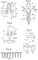
- FIGs. 1-11 of the accompanying drawings show a screw train holding belt according to a first embodiment of the present invention.
- the screw train holding belt designated by reference numeral 1 is made of a soft synthetic resin and has a general configuration which is similar to that of the prior art screw train holding belt shown in Figs. 24-30.
- the screw train holding belt 1 has a pair of longitudinal edges each formed with a multiplicity of engaging notches 1a at a constant pitch. Further, the screw train holding belt 1 is also provided with a multiplicity of screw retaining bores 3 arranged along a longitudinal center line in staggered relation to the engaging notches 1a and defined by respective tubes 2 integral with the belt 1. A plurality of cuts or slits 4 radially extend from each of the screw retaining bores 3 to respective removal facilitating holes 5.
- Each of the screw retaining bores 3 is configured to retain a screw 8 having a threaded shank 8a and a head 8b.
- the screw retaining bore 3 has a diametrically smaller shank retaining portion 3a and a diametrically larger root portion 3b.
- the shank retaining portion 3a is adapted to engage the threaded shank 8a of the screw 8.
- the root portion 3b has its lower and upper edges 3c, 3d contained in an imaginary cone C (see Fig. 2) but is otherwise located diameterically outside the imaginary cone C.
- the root portion 3b of each screw retaining bore 3 is diametrically constant from the upper edge 3d up to an intermediate depth position but then tapers to the lower edge 3c.
- a depressed shoulder 6 is annularly formed in a surface of the belt 1 at each screw retaining bore 3.
- the depressed shoulder 6 radially terminates at the upper edge 3d of the bore root portion 3b and circumferentially interrupted by the corresponding cuts 4 and removal facilitating holes 5.
- each of the cuts 4 associated with the removal facilitating holes 5 radially traverses the bore root portion 3b and extends vertically halfway into the shank retaining bore portion 3a (see Fig. 2).
- the head 8b of the screw 8 retained in the screw retaining bore 3 partially overlaps the removal facilitating holes 5.
- the screw train holding belt 1 described above may be used to hold screws of various configurations.
- the screw 8 may have an undercut head (Figs. 2 and 3) which comes into contact with the upper edge 3d of the root portion 3b of each screw retaining bore 3, an oval countersunk head (Fig. 4) which also comes into contact with the upper edge 3d of the bore root portion 3b, a hexagon head (Fig. 5) which stably rests on the depressed shoulder 6 at the screw retaining bore 3, or a round head (Fig. 6) which stably rests on the belt surface itself.
- the shank 8a of the screw 8 engages in the shank retaining portion 3a of the screw retaining bore 3, whereas an annular clearance 7 is formed around the screw shank 8a in the bore root portion 3b.
- each screw 8 is positively supported at two portions; namely at its shank 8a and head 8b.
- the screw 8 can be reliably held perpendicularly to the belt surface regardless of the configuration of the screw head 8a.
- the depressed shoulder 6 at each screw retaining bore 3 provides a convenient support for the hexagon head 8b or any other diametrically small head. Further, the provision of the depressed shoulder 6 is also preferable in that the projecting length of the bore forming tube 2 can be increased by an amount corresponding to the degree of depression, thereby improving the posture maintaining function of the screw retaining bore 3.
- annular clearance 7 is formed around the screw shank 8a in the root portion 3b of each screw retaining bore 3 (see Figs. 3-6). Such a clearance has been found to be advantageous at least for the following reasons.
- the undercut or oval countershunk head 8b (see Figs. 2-4) of the screw 8 needs only to come into contact with the upper edge 3d of the bore root portion 3b. Therefore, the bore root portion 3b is not required to diametrically expand for adaptation to the undercut or countersunk surface of the screw head 8b.
- the screw train holding belt 1 can be kept substantially straight (see Fig. 10) by preventing it from warping under such expansion, and the belt 1 can be fed smoothly through the screw feeding attachment 12 (see Figs. 21-23).
- the screw head 8b rests stably in the diametrically larger root portion 3b of the screw retaining bore 3 (which has been elastically expanded) immediately before popping out of the screw retaining bore 3. Therefore, it is possible to drive the screw 8 into the object A with a proper orientation.
- each screw retaining bore 3 of the screw train holding belt 1 may be formed by subjecting a belt blank 1' to a burring method which uses, in combination, a punch 9 and a die 10.
- the punch 9 has a diametrically smaller shaft portion 9a, a diametrically larger shaft portion 9b, and a diametrically largest base projection 9c.
- the die 10 has a diametrically smaller bore portion 10a cooperative with the diametrically smaller shaft portion 9a of the punch 9, and a diametrically larger bore portion 10b corresponding to the diametrically larger shaft portion 9b of the punch 9.
- the base projection 9c forms the depressed shoulder 6 at the screw retaining bore 3 (see Figs. 1-6).
- the undercut or oval countershunk head 8b (see Figs. 2-4) of the screw 8 need only come into contact with the upper edge 3d of the bore root portion 3b.
- the undercut or oval countershunk head 8b need not come into full face to face contact with the bore root portion 3b.
- the engaging notches 1a may be formed by punching the belt blank 1' or belt 1 either before or after forming each screw retaining bore 3 by the burring described above. Further, the cuts 4 and removal facilitating holes 5 may be formed simultaneously or separately by punching and/or cutting after the burring. It should be appreciated that the cuts or slits 4 may be made to have a larger width than illustrated in Fig. 1.
- the screw train holding belt 1 may be made by injection molding.
- each removal facilitating hole 5 is optional.
- the removal facilitating hole 5 may be ellipsoidal (second embodiment shown in Fig. 12), triangular or sector-shaped (third embodiment shown in Fig. 13), square (fourth embodiment shown in Fig. 14), generally crescent (fifth embodiment shown in Fig. 15), or shaped like a waterdrop (sixth embodiment shown in Fig. 16).
- each cut 4 may start from the upper edge 3d of the root portion 3b of the screw retaining bore 3, as shown in Fig. 16 showing the sixth embodiment.
- Fig. 17 shows an seventh embodiment of the present invention which is similar to the first embodiment but differs therefrom only in that there is no depressed shoulder (see the element 6 in Figs. 1-6).
- Fig. 18 shows a eighth embodiment of the present invention which is similar to the seventh embodiment but differs therefrom only in that each screw retaining bore 3 is made to have a root portion 3b which is convexly curved outward to be located outside the cone C which contains the lower and upper edges 3c, 3d of the bore root portion 3b.
- Figs. 19 and 20 show a ninth embodiment of the present invention which is similar to the first embodiment (Figs. 1-6) but differs therefrom in that each removal facilitating hole 5 directly opens to the corresponding screw retaining bore 3. Thus, in this embodiment, there is no distinct cut associated with the removal facilitating hole 5 which itself provides the function of a cut.
Landscapes
- Engineering & Computer Science (AREA)
- General Engineering & Computer Science (AREA)
- Mechanical Engineering (AREA)
- Details Of Spanners, Wrenches, And Screw Drivers And Accessories (AREA)
- Devices For Conveying Motion By Means Of Endless Flexible Members (AREA)
- Pulleys (AREA)
Description
- This invention relates to a resinous belt for holding a train of screws. More specifically, the present invention relates to a screw train holding belt which is used in an automatic screw driver for successively feeding screws.
- As often experienced by many people, manual screw driving is a laborious and time-taking job. In particular, the screw driving job can be a serious trouble when it must be done extensively for a long time. For this reason, it has become a common practice to use an automatic screw driver when the screw driving job must be done extensively.
- For the convenience of description, a typical example of automatic screw driver is illustrated in Figs. 21 through 23 of the accompanying drawings. A similar screw driver is also disclosed in U.S. Patent No. 4,059,034 to Hornung.
- As shown in Figs. 21-23, the prior art automatic screw driver mainly comprises a screw driver main 11 and a
screw feeding attachment 12 removably connected to the driver main 11. The driver main 11 carries adriver bit 13 which is rotated by a built-in motor (not shown). - The
screw feeding attachment 12 has anelongate case 14 and aslider 15 slidably fitted in thecase 14. Theslider 15 is always urged forward by acoil spring 16 and carries a pair of indexing sprockets 17 (only one shown) for indexing a screwtrain holding belt 18 which is made of a soft synthetic resin. The screwtrain holding belt 18 carries a train or series ofscrews 19 and has pairs ofnotches 18a for engagement with the pair of indexingsprockets 17 of thescrew feeding attachment 12, as shown in Fig. 24. - In use, the
slider 15 is held in abutment with a suitable portion of an object B (see Fig. 22), and the driver main 11 is pressed forward. As a result, thecase 14 together with thedriver bit 13 in rotation advances to drive a screw 19 (in front of the driver bit 13) of the screwtrain holding belt 18 into the object B while allowing theslider 15 to retreat into thecase 14 against thecoil spring 16. - Upon finishing a screw driving operation, the driver main 11 is brough away from the object B, thereby allowing the
slider 15 to return to its initial position by the storing force of thecoil spring 16. Such a returning movement of theslider 14 causes thesprockets 17 to index the screwtrain holding belt 18 for bringing anotherscrew 19 to a position in front of thedriver bit 13. - As shown in Figs. 24 and 25 (and as disclosed in Japanese Utility Model Publication No. 4(1992)-49367 for example), the screw
train holding belt 18 has a series ofscrew retaining bores 20 at a constant pitch longitudinally of the belt. Each of thescrew retaining bores 20 is defined by atube 21 integral with thebelt 18 for engagement with the threaded shank of thecorresponding screw 19. Further, thescrew retaining bore 20 is surrounded by a plurality ofremoval facilitating holes 22 communicating with thebore 20 via respective cuts orslits 23. Theremoval facilitating holes 22 and thecuts 23 cooperate to facilitate passage of the enlarged head of thescrew 19 through thescrew retaining bore 20 at the time of driving thescrew 19. - When the head of the
screw 19 has a flat bottom, the screwtrain holding belt 18 shown in Figs. 24 and 25 has been found to work well because the screw head can rest stably on the flat surface of the belt to maintain thescrew 19 perpendicular to the belt. However, if thescrew 19 has an undercut or countersunk head which cannot stably rest on the flat belt surface, it becomes difficult for the belt to hold thescrew 19 with correct orientation. - Figs. 26 through 30 of the accompanying drawings show another screw train holding belt 18' which is already known. Such a belt is disclosed in Japanese Utility Model Publication No. 58(1983)-47299 for example.
- As shown in Figs. 26-30, the belt 18' is formed with a series of screw retaining bores 20' each defined by a tube 21' integral with the belt. The screw retaining bore 20' has a
shank retaining portion 20a' (see Fig. 29) for engagement with the threadedshank 19a of thescrew 19, and a conical root portion 20b' for coming into face to face contact with thecountersunk head 19b. - According to the arrangement described above, since the
screw 19 is supported at both of theshank 19a and thehead 19b, it is possible to hold thescrew 19 correctly perpendicular to the belt 18'. However, this prior art belt is still disadvantageus for the following reasons. - As shown in Figs. 27-29, each screw retaining bore 20' of the screw train holding belt 18' is formed by a burring method which uses a
punch 24 and adie 25. Thepunch 24 has a diametricallysmaller shaft portion 24a and a diametrically largerconical portion 24b. Similarly, the die 25 has a diametricallysmaller bore portion 25a and a diametrically largerconical bore portion 25b. Apparently, the screw retaining bore 20' is formed by plastic deformation of the belt material caused by pressing thepunch 24 into the die 25 (see Fig. 28). - However, since the belt 18' is inherently elastic, the conical root portion 20b' tends to spring-back slightly upon drawing the
punch 24 out of the die 25, as appreciated by comparing Fig. 28 with Fig. 29. Thus, it is difficult to form the conical root portion 20b' of the screw retaining bore 20' with dimensional accuracy. - When the
screw 19 is fitted into the thus formed screw retaining bore 20', the conical root portion 20b' of the bore 20' must elastically deform for coming into full face to face contact with thecountersunk head 19b of thescrew 19. As a result, the belt 18' is stressed longitudinally thereof, which causes longitudinal warping of the belt 18', as shown in Fig. 30. Apparently, such warping hinders smooth feeding movement of the belt 18' through the screw feeding attachment 12 (Figs. 21-23). - A similar problem also occurs when the belt 18' is used for holding screws having a countersunk head of a different countersink angle. Further, the conical root portion 20b' of the screw retaining bore 20' cannot adapt to a non-conical undercut screw head.
- It is, therefore, an object of the present invention to provide a screw train holding belt which makes it possible to reliably perform a screw driving operation with ease.
- According to one aspect of the present invention, there is provided a resinous belt for holding a train of screws each having a shank and a head, the belt comprising: a series of screw retaining bores formed in the belt at a predetermined pitch longitudinally of the belt, each of the screw retaining bores being defined by a tube, said each screw retaining bore having a diametrically smaller shank retaining portion for engagement with the shank of the screw, said each screw retaining bore having a diametrically larger root portion which has a first edge adjoining the shank retaining portion and a second edge remote from the shank retaining portion; and a plurality of removal facilitating holes formed in the belt around said each screw retaining bore in communication therewith; characterized in that the root portion of said each screw retaining bore is located radially outside an imaginary cone which contains the first and second edges of the root portion.
- The root portion of said each screw retaining bore may be diametrically constant from the second edge to a position between the first and second edges. Alternatively, the root portion of said each screw retaining bore may be convexly curved outward in cross section vertical to the belt.
- Preferably, a depressed shoulder may be formed around said each screw retaining bore in a surface of the belt which is opposite to the tube.
- Each of the removal facilitating holes may communicate with said each screw retaining bore via a cut which preferably extends into the shank retaining portion of said each screw retaining bore. Alternatively, the removal facilitating hole may open directly to said each screw retaining bore.
- Other objects, features and advantages of the present invention will be fully understood from the following detailed description given with reference to the accompanying drawings, in which:
- Fig. 1 is a fragmentary plan view showing a screw train holding belt according to a first embodiment of the present invention;
- Fig. 2 is a sectional view taken on lines II-II in Fig. 1;
- Fig. 3 is a sectional view taken on lines III-III in Fig. 1;
- Fig. 4 is a sectional view similar to Fig. 3 but showing the same belt as used for holding another type of screws;
- Fig. 5 is a sectional view similar to Fig. 3 but showing the same belt as used for holding a further type of screws;
- Fig. 6 is a sectional view similar to Fig. 3 but showing the same belt as used for holding still another type of screws;
- Fig. 7 is a perspective bottom view showing the same belt at the time of driving a screw;
- Fig. 8 is a sectional view showing the same belt at the time of the screw driving;
- Fig. 9 is a sectional view showing the same belt after the screw driving;
- Fig. 10 is a front view similar showing the belt of Fig. 1 in a reduced scale;
- Fig. 11 is a front view, partly in transverse section, showing the method of making the belt of Fig. 1;
- Fig. 12 is a fragmentary plan view showing a screw train holding belt according to a second embodiment of the present invention;
- Fig. 13 is a fragmentary plan view showing a screw train holding belt according to a third embodiment of the present invention;
- Fig. 14 is a fragmentary plan view showing a screw train holding belt according to a fourth embodiment of the present invention;
- Fig. 15 is a fragmentary plan view showing a screw train holding belt according to a fifth embodiment of the present invention;
- Fig. 16 is a fragmentary plan view showing a screw train holding belt according to a sixth embodiment of the present invention;
- Fig. 17 is a fragmentary view, in transverse section, showing a screw train holding belt according to a seventh embodiment of the present invention;
- Fig. 18 is a fragmentary view, in transverse section, showing a screw train holding belt according to an eighth embodiment of the present invention;
- Fig. 19 is a fragmentary plan view showing a screw train holding belt according to a ninth embodiment of the present invention;
- Fig. 20 is a sectional view taken on lines XX-XX in Fig. 19;
- Fig. 21 is a perspective view showing a prior art screw feeding attachment with which a screw train holding belt according to the present invention as well as a prior art screw train holding belt can be used;
- Fig. 22 is a side view showing the screw feeding attachment as mounted to a screw driver main;
- Fig. 23 is a side view, in longitudinal section, showing the screw feeding attachment with the screw driver main;
- Fig. 24 is a fragmentary plan view showing a prior art screw train holding belt;
- Fig. 25 is a sectional view taken along lines XXV-XXV in Fig. 24;
- Fig. 26 is a front view, in longitudinal section, showing another prior art screw train holding belt;
- Fig. 27 is a perspective view showing a burring method used for making the prior art screw train holding belt of Fig. 26;
- Fig. 28 is a fragmentary sectional view showing the details of the burring method;
- Fig. 29 is a fragmentary sectional view showing the spring back phenomenon occurring after the burring; and
- Fig. 30 is a front view showing the warping of the prior art belt illustrated in Fig. 26.
- Figs. 1-11 of the accompanying drawings show a screw train holding belt according to a first embodiment of the present invention. The screw train holding belt designated by
reference numeral 1 is made of a soft synthetic resin and has a general configuration which is similar to that of the prior art screw train holding belt shown in Figs. 24-30. - Specifically, as shown in Figs. 1-3, the screw
train holding belt 1 has a pair of longitudinal edges each formed with a multiplicity ofengaging notches 1a at a constant pitch. Further, the screwtrain holding belt 1 is also provided with a multiplicity of screw retaining bores 3 arranged along a longitudinal center line in staggered relation to the engagingnotches 1a and defined byrespective tubes 2 integral with thebelt 1. A plurality of cuts orslits 4 radially extend from each of the screw retaining bores 3 to respectiveremoval facilitating holes 5. - Each of the screw retaining bores 3 is configured to retain a
screw 8 having a threadedshank 8a and ahead 8b. Specifically, thescrew retaining bore 3 has a diametrically smallershank retaining portion 3a and a diametricallylarger root portion 3b. Theshank retaining portion 3a is adapted to engage the threadedshank 8a of thescrew 8. Theroot portion 3b has its lower andupper edges root portion 3b of eachscrew retaining bore 3 is diametrically constant from theupper edge 3d up to an intermediate depth position but then tapers to thelower edge 3c. - As shown in Figs. 1 and 2, a
depressed shoulder 6 is annularly formed in a surface of thebelt 1 at eachscrew retaining bore 3. Thedepressed shoulder 6 radially terminates at theupper edge 3d of thebore root portion 3b and circumferentially interrupted by thecorresponding cuts 4 andremoval facilitating holes 5. Further, each of thecuts 4 associated with theremoval facilitating holes 5 radially traverses thebore root portion 3b and extends vertically halfway into the shank retaining boreportion 3a (see Fig. 2). In plane view (Fig. 1), thehead 8b of thescrew 8 retained in thescrew retaining bore 3 partially overlaps theremoval facilitating holes 5. - The screw
train holding belt 1 described above may be used to hold screws of various configurations. For example, thescrew 8 may have an undercut head (Figs. 2 and 3) which comes into contact with theupper edge 3d of theroot portion 3b of eachscrew retaining bore 3, an oval countersunk head (Fig. 4) which also comes into contact with theupper edge 3d of thebore root portion 3b, a hexagon head (Fig. 5) which stably rests on thedepressed shoulder 6 at thescrew retaining bore 3, or a round head (Fig. 6) which stably rests on the belt surface itself. In either case, theshank 8a of thescrew 8 engages in theshank retaining portion 3a of thescrew retaining bore 3, whereas anannular clearance 7 is formed around thescrew shank 8a in thebore root portion 3b. - According to the first embodiment, each
screw 8 is positively supported at two portions; namely at itsshank 8a andhead 8b. Thus, thescrew 8 can be reliably held perpendicularly to the belt surface regardless of the configuration of thescrew head 8a. - As shown in Fig. 5, the
depressed shoulder 6 at eachscrew retaining bore 3 provides a convenient support for thehexagon head 8b or any other diametrically small head. Further, the provision of thedepressed shoulder 6 is also preferable in that the projecting length of thebore forming tube 2 can be increased by an amount corresponding to the degree of depression, thereby improving the posture maintaining function of thescrew retaining bore 3. - As previously described, the
annular clearance 7 is formed around thescrew shank 8a in theroot portion 3b of each screw retaining bore 3 (see Figs. 3-6). Such a clearance has been found to be advantageous at least for the following reasons. - First, due to the
clearance 7, the undercut or oval countershunkhead 8b (see Figs. 2-4) of thescrew 8 needs only to come into contact with theupper edge 3d of thebore root portion 3b. Therefore, thebore root portion 3b is not required to diametrically expand for adaptation to the undercut or countersunk surface of thescrew head 8b. As a result, the screwtrain holding belt 1 can be kept substantially straight (see Fig. 10) by preventing it from warping under such expansion, and thebelt 1 can be fed smoothly through the screw feeding attachment 12 (see Figs. 21-23). - Secondly, as shown in Figs. 7 through 9, when the
screw 8 is forced out the screw retaining bore 3 (or the bore forming tube 2) by the driver bit 13 (see also Fig. 23) for driving into an object A, thescrew retaining bore 3 must be diametrically expanded against the elastic restoring force of thetube 2 to allow passage of thescrew head 8b. However, since the amount of the diametrical expansion is reduced by the presence of theannular clearance 7, the force required for such expansion is correspondingly reduced. As a result, the screw driving operation can be facilitated. It should be appreciated in this regard that thecuts 4 andremoval facilitating holes 5 associated with thescrew retaining bore 3 also contribute greatly for facilitating the screw driving operation. - As shown in Fig. 8, the
screw head 8b rests stably in the diametricallylarger root portion 3b of the screw retaining bore 3 (which has been elastically expanded) immediately before popping out of thescrew retaining bore 3. Therefore, it is possible to drive thescrew 8 into the object A with a proper orientation. - As shown in Fig. 11, each
screw retaining bore 3 of the screwtrain holding belt 1 may be formed by subjecting a belt blank 1' to a burring method which uses, in combination, apunch 9 and adie 10. Thepunch 9 has a diametricallysmaller shaft portion 9a, a diametricallylarger shaft portion 9b, and a diametricallylargest base projection 9c. Thedie 10 has a diametricallysmaller bore portion 10a cooperative with the diametricallysmaller shaft portion 9a of thepunch 9, and a diametricallylarger bore portion 10b corresponding to the diametricallylarger shaft portion 9b of thepunch 9. Apparently, thebase projection 9c forms thedepressed shoulder 6 at the screw retaining bore 3 (see Figs. 1-6). - As described above, the undercut or oval countershunk
head 8b (see Figs. 2-4) of thescrew 8 need only come into contact with theupper edge 3d of thebore root portion 3b. In other words, the undercut or oval countershunkhead 8b need not come into full face to face contact with thebore root portion 3b. Thus, it is unnecessary to form thebore root portion 3b with strict dimensional accuracy, so that the burring operation described above may be conveniently performed without paying attention to dimensional accuracy. - The engaging
notches 1a may be formed by punching the belt blank 1' orbelt 1 either before or after forming eachscrew retaining bore 3 by the burring described above. Further, thecuts 4 andremoval facilitating holes 5 may be formed simultaneously or separately by punching and/or cutting after the burring. It should be appreciated that the cuts orslits 4 may be made to have a larger width than illustrated in Fig. 1. - As an alternative to the burring and punching (or cutting) described above, the screw
train holding belt 1 may be made by injection molding. - The configuration of each
removal facilitating hole 5 is optional. For example, theremoval facilitating hole 5 may be ellipsoidal (second embodiment shown in Fig. 12), triangular or sector-shaped (third embodiment shown in Fig. 13), square (fourth embodiment shown in Fig. 14), generally crescent (fifth embodiment shown in Fig. 15), or shaped like a waterdrop (sixth embodiment shown in Fig. 16). Further, each cut 4 may start from theupper edge 3d of theroot portion 3b of thescrew retaining bore 3, as shown in Fig. 16 showing the sixth embodiment. - Fig. 17 shows an seventh embodiment of the present invention which is similar to the first embodiment but differs therefrom only in that there is no depressed shoulder (see the
element 6 in Figs. 1-6). - Fig. 18 shows a eighth embodiment of the present invention which is similar to the seventh embodiment but differs therefrom only in that each
screw retaining bore 3 is made to have aroot portion 3b which is convexly curved outward to be located outside the cone C which contains the lower andupper edges bore root portion 3b. - Figs. 19 and 20 show a ninth embodiment of the present invention which is similar to the first embodiment (Figs. 1-6) but differs therefrom in that each
removal facilitating hole 5 directly opens to the correspondingscrew retaining bore 3. Thus, in this embodiment, there is no distinct cut associated with theremoval facilitating hole 5 which itself provides the function of a cut.
Claims (9)
- A resinous belt for holding a train of screws (8) each having a shank (8a) and a head (8b), the belt (1) comprising: a series of screw retaining bores (3) formed in the belt (1) at a predetermined pitch longitudinally of the belt (1), each of the screw retaining bores (3) being defined by a tube (2), said each screw retaining bore (3) having a diametrically smaller shank retaining portion (3a) for engagement with the shank (8a) of the screw (8), said each screw retaining bore (3) having a diametrically larger root portion (3b) which has a first edge (3c) adjoining the shank retaining portion (3a) and a second edge (3d) remote from the shank retaining portion (3a); and a plurality of removal facilitating holes (5) formed in the belt (1) around said each screw retaining bore (3) in communication therewith;
characterized in that the root portion (3b) of said each screw retaining bore (3) is located radially outside an imaginary cone (C) which contains the first and second edges (3c, 3d) of the root portion (3b). - The belt according to claim 1, wherein the root portion (3b) of said each screw retaining bore (3) is diametrically constant from the second edge (3d) to a position between the first and second edges (3c, 3d).
- The belt according to claim 1 or 2, wherein the root portion (3b) of said each screw retaining bore (3) is diametrically constant from the second edge (3d) to a position short of the first edge (3c) but beyond a surface of the belt (1) from which the tube (2) projects.
- The belt according to claim 1, wherein the root portion (3b) of said each screw retaining bore (3) is convexly curved outward in cross section vertical to the belt (1).
- The belt according to any one of claims 1 to 4, further comprising a depressed shoulder (6) formed around said each screw retaining bore (3) in a surface of the belt (1) which is opposite to the tube (2).
- The belt according to any one of claims 1 to 5, wherein each of the removal facilitating holes (5) communicates with said each screw retaining bore (3) via a cut (4).
- The belt according to claim 6, wherein the cut (4) extends into the shank retaining portion (3a) of said each screw retaining bore (3).
- The belt according to any one of claims 1 to 5, wherein each of the removal facilitating holes (5) opens directly to said each screw retaining bore (3).
- The belt according to any one of claims 1 to 8, wherein each of the removal facilitating holes (5) is partially covered by the head (8b) of the screw (8).
Applications Claiming Priority (2)
| Application Number | Priority Date | Filing Date | Title |
|---|---|---|---|
| JP1993055376U JP2593069Y2 (en) | 1993-10-13 | 1993-10-13 | Screw holding belt |
| JP55376/93U | 1993-10-13 |
Publications (3)
| Publication Number | Publication Date |
|---|---|
| EP0648579A2 EP0648579A2 (en) | 1995-04-19 |
| EP0648579A3 EP0648579A3 (en) | 1996-01-10 |
| EP0648579B1 true EP0648579B1 (en) | 1997-07-02 |
Family
ID=12996775
Family Applications (1)
| Application Number | Title | Priority Date | Filing Date |
|---|---|---|---|
| EP94307537A Expired - Lifetime EP0648579B1 (en) | 1993-10-13 | 1994-10-13 | Belt for holding a train of screws |
Country Status (4)
| Country | Link |
|---|---|
| US (1) | US5544746A (en) |
| EP (1) | EP0648579B1 (en) |
| JP (1) | JP2593069Y2 (en) |
| DE (1) | DE69404014T2 (en) |
Families Citing this family (32)
| Publication number | Priority date | Publication date | Assignee | Title |
|---|---|---|---|---|
| US5934162A (en) * | 1993-02-17 | 1999-08-10 | Habermehl; G. Lyle | Screwdriver with dual cam slot for collated screws |
| US5758768A (en) * | 1996-06-28 | 1998-06-02 | G. Lyle Habermehl | Supporting deflective screwstrip |
| JP2869045B2 (en) * | 1996-09-24 | 1999-03-10 | 有限会社新城製作所 | Screw retaining belt for bladed drill screw |
| DE29620053U1 (en) * | 1996-11-19 | 1997-01-09 | Adolf Würth GmbH & Co. KG, 74653 Künzelsau | Magazine tape for fasteners |
| US5775514A (en) * | 1997-02-28 | 1998-07-07 | Lin; Jack | Screw band |
| US5803691A (en) * | 1997-06-09 | 1998-09-08 | Huang; Shih Chang | Strip for supporting nails |
| DE19747024C2 (en) * | 1997-10-24 | 2000-11-02 | Reich Maschf Gmbh Karl | Screw belt and associated magazine screwdriver |
| US5931298A (en) * | 1998-02-04 | 1999-08-03 | Huang; Shih Chang | Strip for supporting nails |
| US6394268B1 (en) | 2000-09-29 | 2002-05-28 | Illinois Tool Works Inc. | Nail-type fastener collation strip with fastener guide rings, and combination thereof |
| AUPR576501A0 (en) * | 2001-06-18 | 2001-07-12 | Russell Mineral Equipment Pty Ltd | Rock bolting apparatus and method |
| JP2003336614A (en) * | 2002-05-20 | 2003-11-28 | Shinjo Seisakusho:Kk | Screw retention belt |
| US20040006860A1 (en) * | 2002-07-15 | 2004-01-15 | Haytayan Harry M. | Method and apparatus for attaching structural components with fasteners |
| US8074348B2 (en) * | 2002-07-15 | 2011-12-13 | Haytayan Harry M | Apparatus and method for fastening together structural components |
| US20040118720A1 (en) * | 2002-12-18 | 2004-06-24 | Powers Fasteners, Inc. | Fastener carrier assembly and method of use |
| US7021462B2 (en) * | 2002-12-18 | 2006-04-04 | Powers Fasteners, Inc. | Fastener carrier assembly and method of use |
| US7051875B2 (en) * | 2003-12-17 | 2006-05-30 | Simpson Strong-Tie Company, Inc. | Holding strap for curved screwstrip |
| US20060006088A1 (en) * | 2004-07-08 | 2006-01-12 | Chao-Wei Lin | Screw strip |
| US7520385B2 (en) * | 2005-01-31 | 2009-04-21 | Esgw Holdings Limited | Packaging substrate and presentation of small hardware |
| CN100496901C (en) * | 2006-04-18 | 2009-06-10 | 宽仕工业股份有限公司 | Screw chain belt with continuous convex rib |
| US7406899B2 (en) | 2006-07-24 | 2008-08-05 | Walker Douglas W | Automatic feed medical screwdriver |
| JP4745906B2 (en) * | 2006-07-24 | 2011-08-10 | 日本パワーファスニング株式会社 | Connecting screw |
| US20080131233A1 (en) * | 2006-10-17 | 2008-06-05 | Yao Chun I | Plate-shaped fastener device |
| USD605016S1 (en) | 2007-08-17 | 2009-12-01 | Simpson Strong-Tie Company, Inc. | Collation strip |
| DE102007058051B3 (en) * | 2007-11-30 | 2009-08-20 | Phoenix Contact Gmbh & Co. Kg | Arrangement for screw locking of electrical connection terminals |
| US8262669B2 (en) * | 2009-01-14 | 2012-09-11 | Walker Douglas W | Method for using an automatic feed medical screwdriver |
| EP2628606A3 (en) * | 2011-07-19 | 2013-11-27 | GRATZER! Technologies GmbH & Co. KG | Carrier strip with decorative elements, and method and apparatus for fixing rigid decorative elements on a substrate |
| DE102013019452B4 (en) * | 2013-11-21 | 2019-05-29 | Rose Plastic Ag | Single packaging for elongated objects |
| WO2016085901A1 (en) | 2014-11-25 | 2016-06-02 | DePuy Synthes Products, Inc. | Medical device identification system |
| JP6324359B2 (en) * | 2015-10-21 | 2018-05-16 | 株式会社椿本チエイン | Chain guide |
| KR101990970B1 (en) * | 2019-02-15 | 2019-06-20 | 주식회사 명보테크 | Emboss band for screw storage |
| US10816025B1 (en) * | 2019-08-23 | 2020-10-27 | Guangzhe Enterprise Co., Ltd. | Screw band |
| US12365066B2 (en) | 2020-10-14 | 2025-07-22 | Simpson Strong-Tie Company Inc. | Fastener installation systems and adapters |
Family Cites Families (15)
| Publication number | Priority date | Publication date | Assignee | Title |
|---|---|---|---|---|
| US2877681A (en) * | 1954-04-16 | 1959-03-17 | Set Screw & Mfg Company | Screw having deformable temporary head disposed in a groove |
| US3097360A (en) * | 1961-06-26 | 1963-07-16 | Jr Carl J Carlson | Fastener assemblage |
| US3211284A (en) * | 1962-07-23 | 1965-10-12 | Edgar P Anstett | Nailing strip |
| US3506115A (en) * | 1967-04-03 | 1970-04-14 | Gen Wire Overseas Corp | Nail holding disk for use in nailing machine |
| DE2211511A1 (en) * | 1972-03-10 | 1973-09-20 | Dieter Haubold Ind Nagelgeraet | MAGAZINE STRIP FOR A DEVICE FOR DRIVING DECORATIVE NAILS |
| SE386135B (en) * | 1973-03-09 | 1976-08-02 | Bulten Kanthal Ab | BANDED, SHORT SCREW. |
| DE7521374U (en) * | 1975-07-05 | 1975-10-30 | Helfer & Co Kg Feinwerkbau | Screw belt of a screw pulling device |
| DE2541046C2 (en) * | 1975-09-15 | 1982-10-14 | Feinwerkbau Helfer & Co KG, 3261 Möllenbeck | Feed device on a driving tool for feeding fastening means, in particular screws |
| JPS5847299A (en) * | 1981-09-16 | 1983-03-18 | 株式会社東芝 | Auxialiary boiler device of atomic power plant |
| US4955476A (en) * | 1986-12-25 | 1990-09-11 | Matsushita Electric Industrial Co., Ltd. | Fastener carrier for the support of screw members |
| AT389745B (en) * | 1987-10-21 | 1990-01-25 | Sfs Stadler Ag | MAGAZINE STRIP FOR FASTENERS |
| JPH0449367A (en) * | 1990-06-15 | 1992-02-18 | Yokohama Rubber Co Ltd:The | Construction for removable floor panel and executing method for work for removable floor panel |
| ATE127060T1 (en) * | 1991-09-16 | 1995-09-15 | Sheh Fung Screws Co Ltd | DEVICE FOR POSITIONING AND FEEDING SCREWS. |
| US5256012A (en) * | 1991-12-10 | 1993-10-26 | Mikels Marshall E | Packaging format and a positioning device for fasteners and the like |
| DE9305336U1 (en) * | 1993-04-07 | 1994-08-11 | Ludwig Hettich Schraubenfabrik GmbH & Co, 78713 Schramberg | Magazine belt |
-
1993
- 1993-10-13 JP JP1993055376U patent/JP2593069Y2/en not_active Expired - Fee Related
-
1994
- 1994-10-11 US US08/321,107 patent/US5544746A/en not_active Expired - Fee Related
- 1994-10-13 DE DE69404014T patent/DE69404014T2/en not_active Expired - Fee Related
- 1994-10-13 EP EP94307537A patent/EP0648579B1/en not_active Expired - Lifetime
Also Published As
| Publication number | Publication date |
|---|---|
| DE69404014T2 (en) | 1998-03-26 |
| JP2593069Y2 (en) | 1999-03-31 |
| EP0648579A2 (en) | 1995-04-19 |
| EP0648579A3 (en) | 1996-01-10 |
| JPH0725322U (en) | 1995-05-12 |
| US5544746A (en) | 1996-08-13 |
| DE69404014D1 (en) | 1997-08-07 |
Similar Documents
| Publication | Publication Date | Title |
|---|---|---|
| US5544746A (en) | Belt for holding a train of screws | |
| US6599063B1 (en) | Hole saw having efficient slug removal | |
| US4452556A (en) | Plastic headed fastener | |
| EP0978333B1 (en) | Punch holder apparatus | |
| DE69303969T2 (en) | Washer for cutting tool | |
| US2593506A (en) | Method and apparatus for punching materials with screws and lodging same therein | |
| US4233873A (en) | Permanent magnetic hold down for steel rule dies | |
| US3602974A (en) | Pierce nut fastening means and method | |
| CA2465394A1 (en) | Knurled fastener with cutting edges and removable head | |
| US5230132A (en) | Method of use for a multiple bond sizing and repairing device | |
| US4829867A (en) | Paper punch apparatus with improved punch element | |
| GB2025559A (en) | Rivet body | |
| US5056976A (en) | Wire nail, strip of collated wire nails, and related apparatus | |
| US2084079A (en) | Screw | |
| US4839952A (en) | Process for manufacturing toothed parts | |
| US4165673A (en) | Metal stamped and formed screw | |
| US391097A (en) | Island | |
| US4478115A (en) | Tamper-resistant fastener key | |
| US5615985A (en) | Collated fastener strip | |
| US20040065136A1 (en) | Expandable forming tool | |
| EP1405682B1 (en) | Expandable forming tool | |
| US4932234A (en) | Method of forming tappet adjusting screws | |
| US5533379A (en) | Method of forming a head on a fastener | |
| US11624392B2 (en) | Wing-shaped thrust screw assembly | |
| US5119659A (en) | Device for changing stroke of caulking machine |
Legal Events
| Date | Code | Title | Description |
|---|---|---|---|
| PUAI | Public reference made under article 153(3) epc to a published international application that has entered the european phase |
Free format text: ORIGINAL CODE: 0009012 |
|
| AK | Designated contracting states |
Kind code of ref document: A2 Designated state(s): DE FR GB IT SE |
|
| PUAL | Search report despatched |
Free format text: ORIGINAL CODE: 0009013 |
|
| AK | Designated contracting states |
Kind code of ref document: A3 Designated state(s): DE FR GB IT SE |
|
| 17P | Request for examination filed |
Effective date: 19960115 |
|
| GRAG | Despatch of communication of intention to grant |
Free format text: ORIGINAL CODE: EPIDOS AGRA |
|
| 17Q | First examination report despatched |
Effective date: 19960930 |
|
| GRAH | Despatch of communication of intention to grant a patent |
Free format text: ORIGINAL CODE: EPIDOS IGRA |
|
| GRAH | Despatch of communication of intention to grant a patent |
Free format text: ORIGINAL CODE: EPIDOS IGRA |
|
| GRAA | (expected) grant |
Free format text: ORIGINAL CODE: 0009210 |
|
| AK | Designated contracting states |
Kind code of ref document: B1 Designated state(s): DE FR GB IT SE |
|
| PG25 | Lapsed in a contracting state [announced via postgrant information from national office to epo] |
Ref country code: IT Free format text: LAPSE BECAUSE OF FAILURE TO SUBMIT A TRANSLATION OF THE DESCRIPTION OR TO PAY THE FEE WITHIN THE PRE;WARNING: LAPSES OF ITALIAN PATENTS WITH EFFECTIVE DATE BEFORE 2007 MAY HAVE OCCURRED AT ANY TIME BEFORE 2007. THE CORRECT EFFECTIVE DATE MAY BE DIFFERENT FROM THE ONE RECORDED.SCRIBED TIME-LIMIT Effective date: 19970702 |
|
| REF | Corresponds to: |
Ref document number: 69404014 Country of ref document: DE Date of ref document: 19970807 |
|
| ET | Fr: translation filed | ||
| PLBE | No opposition filed within time limit |
Free format text: ORIGINAL CODE: 0009261 |
|
| STAA | Information on the status of an ep patent application or granted ep patent |
Free format text: STATUS: NO OPPOSITION FILED WITHIN TIME LIMIT |
|
| 26N | No opposition filed | ||
| PGFP | Annual fee paid to national office [announced via postgrant information from national office to epo] |
Ref country code: GB Payment date: 20010924 Year of fee payment: 8 |
|
| PGFP | Annual fee paid to national office [announced via postgrant information from national office to epo] |
Ref country code: SE Payment date: 20011001 Year of fee payment: 8 |
|
| PGFP | Annual fee paid to national office [announced via postgrant information from national office to epo] |
Ref country code: FR Payment date: 20011003 Year of fee payment: 8 |
|
| PGFP | Annual fee paid to national office [announced via postgrant information from national office to epo] |
Ref country code: DE Payment date: 20011004 Year of fee payment: 8 |
|
| REG | Reference to a national code |
Ref country code: GB Ref legal event code: IF02 |
|
| PG25 | Lapsed in a contracting state [announced via postgrant information from national office to epo] |
Ref country code: GB Free format text: LAPSE BECAUSE OF NON-PAYMENT OF DUE FEES Effective date: 20021013 |
|
| PG25 | Lapsed in a contracting state [announced via postgrant information from national office to epo] |
Ref country code: SE Free format text: LAPSE BECAUSE OF NON-PAYMENT OF DUE FEES Effective date: 20021014 |
|
| PG25 | Lapsed in a contracting state [announced via postgrant information from national office to epo] |
Ref country code: DE Free format text: LAPSE BECAUSE OF NON-PAYMENT OF DUE FEES Effective date: 20030501 |
|
| EUG | Se: european patent has lapsed | ||
| GBPC | Gb: european patent ceased through non-payment of renewal fee |
Effective date: 20021013 |
|
| PG25 | Lapsed in a contracting state [announced via postgrant information from national office to epo] |
Ref country code: FR Free format text: LAPSE BECAUSE OF NON-PAYMENT OF DUE FEES Effective date: 20030630 |
|
| REG | Reference to a national code |
Ref country code: FR Ref legal event code: ST |