EP0645268B1 - Flap-type pressure relief valve and method of forming same - Google Patents
Flap-type pressure relief valve and method of forming same Download PDFInfo
- Publication number
- EP0645268B1 EP0645268B1 EP94115136A EP94115136A EP0645268B1 EP 0645268 B1 EP0645268 B1 EP 0645268B1 EP 94115136 A EP94115136 A EP 94115136A EP 94115136 A EP94115136 A EP 94115136A EP 0645268 B1 EP0645268 B1 EP 0645268B1
- Authority
- EP
- European Patent Office
- Prior art keywords
- tab
- sheet
- frame
- aperture
- pressure relief
- Prior art date
- Legal status (The legal status is an assumption and is not a legal conclusion. Google has not performed a legal analysis and makes no representation as to the accuracy of the status listed.)
- Expired - Lifetime
Links
Images


Classifications
-
- F—MECHANICAL ENGINEERING; LIGHTING; HEATING; WEAPONS; BLASTING
- F24—HEATING; RANGES; VENTILATING
- F24F—AIR-CONDITIONING; AIR-HUMIDIFICATION; VENTILATION; USE OF AIR CURRENTS FOR SCREENING
- F24F13/00—Details common to, or for air-conditioning, air-humidification, ventilation or use of air currents for screening
- F24F13/08—Air-flow control members, e.g. louvres, grilles, flaps or guide plates
- F24F13/18—Air-flow control members, e.g. louvres, grilles, flaps or guide plates specially adapted for insertion in flat panels, e.g. in door or window-pane
-
- B—PERFORMING OPERATIONS; TRANSPORTING
- B60—VEHICLES IN GENERAL
- B60H—ARRANGEMENTS OF HEATING, COOLING, VENTILATING OR OTHER AIR-TREATING DEVICES SPECIALLY ADAPTED FOR PASSENGER OR GOODS SPACES OF VEHICLES
- B60H1/00—Heating, cooling or ventilating devices
- B60H1/24—Ventilating devices where the heating or cooling is irrelevant
- B60H1/248—Air-extractors, air-evacuation from the vehicle interior
- B60H1/249—Air-extractors, air-evacuation from the vehicle interior using one-way valves
-
- F—MECHANICAL ENGINEERING; LIGHTING; HEATING; WEAPONS; BLASTING
- F16—ENGINEERING ELEMENTS AND UNITS; GENERAL MEASURES FOR PRODUCING AND MAINTAINING EFFECTIVE FUNCTIONING OF MACHINES OR INSTALLATIONS; THERMAL INSULATION IN GENERAL
- F16K—VALVES; TAPS; COCKS; ACTUATING-FLOATS; DEVICES FOR VENTING OR AERATING
- F16K15/00—Check valves
- F16K15/14—Check valves with flexible valve members
- F16K15/16—Check valves with flexible valve members with tongue-shaped laminae
-
- Y—GENERAL TAGGING OF NEW TECHNOLOGICAL DEVELOPMENTS; GENERAL TAGGING OF CROSS-SECTIONAL TECHNOLOGIES SPANNING OVER SEVERAL SECTIONS OF THE IPC; TECHNICAL SUBJECTS COVERED BY FORMER USPC CROSS-REFERENCE ART COLLECTIONS [XRACs] AND DIGESTS
- Y10—TECHNICAL SUBJECTS COVERED BY FORMER USPC
- Y10T—TECHNICAL SUBJECTS COVERED BY FORMER US CLASSIFICATION
- Y10T137/00—Fluid handling
- Y10T137/7722—Line condition change responsive valves
- Y10T137/7837—Direct response valves [i.e., check valve type]
- Y10T137/7879—Resilient material valve
- Y10T137/7888—With valve member flexing about securement
- Y10T137/7891—Flap or reed
- Y10T137/7892—With stop
Definitions
- the subject invention is directed toward the art of air vents for vehicles and, more particularly, to a flap-type check or pressure relief valve for controlling the flow of air into and out of a vehicle.
- Flap-type check valves are widely used in the motor vehicle art to relieve air pressure surges or peaks in the passenger compartment which result, for example, when the doors are slammed shut.
- the valves generally comprise a simple rigid frame or housing which mounts in a vehicle body panel opening and provides one or more air outlets.
- a valve element in the form of a flexible sheet is joined along one edge to the frame to overlie the outlets on the side exterior to the vehicle compartment.
- valve element sheets have been connected to the frame using a variety of techniques, including separate mechanical fasteners, heat welding processes, and molded tabs. See, for example, U.S. Patent Nos. 4,972,765 and 4,667,578 which disclose the various prior art connecting techniques.
- the subject invention provides a flap-type valve and frame assembly which greatly simplifies and improves the relationship between the flap valve elements and their supporting frame. Through the use of the invention, the connection between the frame and the flap valve is a sealed, airtight connection and assembly is greatly facilitated.
- a pressure relief valve having a frame with a flow opening therethrough and a valve element in the form of a flexible sheet of material mounted to the frame to overlie the flow opening is provided with improved connecting means for mounting the flexible sheet to the frame.
- the connecting means comprises at least one connecting aperture through the frame along a first side of the flow opening and a tab element on a first edge of the sheet extending through the aperture.
- the tab element which is co-planar to said flexible sheet, is formed of resilient and compressible elastic material and has enlarged first and second portions extending outwardly about the aperture on both side faces of the frame with a connecting portion between the first and second portions.
- the connecting portion is located within the connecting aperture and is sized so that it is under compression by the frame and completely fills the connecting aperture.
- the tab element is molded integrally with the flexible sheet.
- the connecting portion located within the connecting aperture is compressed by the frame and is under tension between the first and second portions so as to cause the first and second portions to compress against the opposite side faces of the frame.
- the tab element has an outer free end which is smaller than the connecting aperture and the tab gradually increases in size from the outer free end to the first enlarged portion.
- the tab elements located along the first edge of the sheet and individually received in separate apertures extending through the frame along the first side edge of the flow opening.
- the tab element is preferably joined to the flexible sheet through a thin and flexible hinge portion.
- the tab By the use of tab portions that are sized and related to the frame apertures as described, the tab totally seals the connecting aperture.
- the tab portion By proper design of the tab portion, installation and connection of the flexible sheet which forms the valve element is greatly facilitated and the connector can be an integral part of the sheet or valve element.
- the entire assembly can consist solely of the flap valve and the frame. Both of the elements can be formed using well known plastic molding techniques.
- a method of forming a flap-type pressure relief valve which comprises providing a relatively rigid frame defining a flow passage with a flow outlet opening having a first wall extending along a first side of the opening.
- a connecting aperture is provided through the first wall at a location adjacent the flow outlet opening.
- a valve element is provided in the form of a relatively thin sheet of material of a size sufficient to completely overlie the flow outlet opening.
- the sheet has a co-planar tab extending from an edge thereof with the tab being formed from a resilient elastomeric material and including a base joined to the sheet, a tab body terminating in an outer free end of a cross-section less than the connecting aperture.
- the tab body includes an intermediate portion between the base and the free end that, in its relaxed state, is larger in cross-section than the connecting aperture but can be reduced to a cross-section less than the connecting aperture by applying tension between the base and the free end.
- the sheet is positioned over the flow outlet opening with the tab aligned with the connecting aperture and thereafter the free end of the tab is placed through the aperture and tension is applied to the tab portion to reduce the cross-section of the intermediate portion sufficiently to allow the intermediate portion to enter the connecting aperture. Thereafter, the tension on the tab is released to allow the intermediate portion to expand into a compressed and engaged state with the walls of the aperture.
- the free end portion of the tab is removed after the intermediate portion is in the aperture.
- the tab portion is removed by providing a thin frangible section in the free end portion with the frangible section designed such that it fractures when the force applied thereto slightly exceeds the force necessary to reduce the intermediate portion to a size such that it can be inserted into the aperture.
- the primary object of the invention is the provision of a flap-type valve structure which has an improved connection arrangement between the flap valve and its supporting frame structure and the connecting means for the flap valve comprises an integral tab formed on the flap valve with the tab forming both the connecting means and the flap valve hinge element.
- a further object is the provision of a flap-type check valve of the general type described wherein the entire assembly comprises a main frame and the desired number of flap valve elements with all of the connectors being integrally formed on the flap valves.
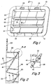
- FIGURES 1 through 4 best illustrate the overall arrangement of the preferred embodiment of a flap valve element formed in accordance with the subject invention.
- the flap valve assembly is identified with the numeral 10 and includes a generally vertically oriented, relatively rigid main frame 12 that carries three separate spaced valve flaps 14 , 16 , and 18 .
- the flaps are positioned in vertically spaced relationship. It should be readily understood, however, that the particular number and arrangement of the flaps relative to the frame is not of significance to the invention and other different arrangements could be used.
- the frame 12 can best be understood by reference to FIGURES 1, 2, and 4. As shown therein, the frame 12 includes a main, circumferentially extending, rigid peripheral flange 20 that has a generally rectangular shape with suitably rounded corners and supports a second, axially extending, inner peripheral flange 22 . Suitable mounting openings 24 are carried in the flange 20 . The openings 24 provide means for joining the valve assembly to the associated vehicle support panels, walls, or the like.
- a somewhat grid-like structure is supported from the end of the flange 22 and comprises a pair of vertically extending end members shown as rails 26 and a plurality of partition walls 28 that are generally vertically oriented and cross-connected with inclined dividing panels or walls 30 .
- the walls and panels define a grid structure as illustrated in FIGURE 4 with three rows of aligned rectangular airflow outlet openings.
- each horizontal row of the through openings defined by walls 28 and 30 are relatively narrow connecting strips 32 that extend horizontally between the rails 26 .
- Each strip 32 is pierced by three collinear, horizontally extending narrow slots 34 .
- the slots 34 provide means for receiving and retaining the individually flaps 14 , 16 , and 18 in a manner subsequently to be described.
- the walls 28 and 30 are arranged so that the outlets of the through openings are on an incline such as can readily be seen in FIGURES 2 and 4. This inclined arrangement assures that the valve flaps will normally be closed under the influence of gravity in the manner shown in FIGURE 1.
- the flaps 14 , 16 , and 18 will lift off their supporting framework and move to an open position such as shown in phantom in FIGURE 2.
- each of the valve flaps 14 , 16 , and 18 is formed as a single, relatively thin flexible sheet of material such as illustrated in FIGURES 4 and 5 having a longitudinal extent as shown and being formed from a resilient, flexible elastomeric material or a suitable plastics material, such as polyethylene or polyvinyl chloride having the necessary resiliency and physical characteristics required.
- each of the valve flaps includes the relatively thin, flexible main valve sheet 40 and a plurality of co-planar tabs 42 .
- the valve sheet 40 and the connecting tabs 42 are formed as an extrusion molding that has constant cross-section in planes perpendicular to the length of the flap.
- the final shape and form is best shown in FIGURES 3 and 6A through 6D. This form is achieved by cutting the extrusion molding to have the desired peripheral shape.
- the valve sheet 40 joins the individual tabs through a reduced thickness portion 45 .
- the reduced thickness portion 45 extends the length of the main body and forms a living hinge so as to provide a substantial degree of flexibility between the main body and the connecting portions 44 of the tabs 42 .
- the connecting portion 44 is, as will become apparent, sized according to the size of the slots 34 so as to provide a tight sealed connection between the valve flaps and the supporting frame 12 .
- the connecting portion 44 comprises a pair of relatively heavy, enlarged first and second retaining ribs 46 and 48 separated by an intermediate portion 50 .
- the intermediate portion 50 has a cross-sectional shape including a length and thickness which is, in its relaxed state, greater than the length and width of the slot 34 .
- the ribs 46 and 48 are, however, thicker than the width of the slot 34 by a relatively substantial amount.
- the retaining rib 48 is provided with a tapered cross-section which joins through a relatively narrow, reduced thickness portion 52 with an elongated, tapered tab end 54 .
- the thickness of portion 48 preferably gradually increases until its juncture with the reduced intermediate section 50 .
- the thickness of the tab end 54 at its outer free end is preferably somewhat smaller than the width of the slot 34 .
- FIGURES 6A through 6D This sequence of assembly steps is best seen in FIGURES 6A through 6D.
- the outer, reduced-size tab end 54 is inserted through the associated slot 34 and a pulling force is applied to the tab end 54 to pull the tab 42 into the slot.
- the longitudinal pulling and the taper of the retention rib 48 are such that the ribs 48 can be pulled through the slot 34 to seat the connecting portion 50 within the slot 34 . This is possible because of the reduction in cross-sectional size which results from the longitudinal tension applied to the connecting portion and the end tab portion 54 .
Landscapes
- Engineering & Computer Science (AREA)
- Mechanical Engineering (AREA)
- General Engineering & Computer Science (AREA)
- Chemical & Material Sciences (AREA)
- Combustion & Propulsion (AREA)
- Physics & Mathematics (AREA)
- Thermal Sciences (AREA)
- Check Valves (AREA)
Description
Claims (8)
- Flap type pressure relief valve having a frame (12) with opposite side faces including a flow opening therethrough and a valve element in the form of a flexible sheet (40) of material having a first edge and mounted to the frame (12) along a first side of the flow opening to overlie the flow opening, improved connecting means for mounting the flexible sheet (40) to the frame (12) comprising at least one connecting aperture through the frame (12) along the first side of the flow opening and a tab element (42) on the first edge of the sheet (40) and extending through the connecting aperture, the tab element (42) being formed of resilient and compressible elastomeric material and having enlarged first and second portions (46, 48) extending outwardly about the connecting aperture on both side faces of the frame (12) with a connecting portion (44) between the first and second portions (46, 48), said connecting portion (44) located within the connecting aperture,
characterized in that
the connecting portion (44) in the connecting aperture being under compression and completely filling the connecting aperture and compressively engaging the frame and
that said tab element (42) is co-planar to said flexible sheet (40). - Flap type pressure relief valve as defined in claim 1 wherein the tab element (42) is molded integrally to the flexible sheet (40).
- Flap type pressure relief valve as defined in claim 2 wherein the tab element (42) and the flexible sheet (40) are formed from the same material.
- Flap type pressure relief valve as defined in claim 1 wherein the tab element (42) has an outer free end (54) which is smaller than said connecting aperture, said tab element (42) gradually increasing in size from the outer free end (54) to the first enlarged portion (48).
- Flap type pressure relief valve as defined in claim 1 wherein the tab element (42) is joined to the flexible sheet (40) through a thin and flexible hinge portion (45),
wherein preferably there are a plurality of the tab elements (42) along the first edge of the sheet (40),
wherein preferably the flow opening lies in a plane and the frame (12) has a first wall which extends transversely of the flow opening of the plane, and further wherein the connecting aperture extends through the first wall,
wherein preferably there are a plurality of connecting apertures and a plurality of tab elements (42) associated with the valve element. - Flap type pressure relief valve as defined in claim 1 wherein the connecting portion (44) of the tab (42) is under axial tension between the first and second enlarged portions (46, 48).
- Flap type pressure relief valve as defined in claims 1 or 6 wherein the tab (42) and the sheet (40) are extrusion molded from the same elastomeric material,
wherein preferably the tab (42) is integral with the sheet (40) and joins to the sheet (40) through a thin flexible hinge section (45) for permitting free swinging of the sheet (40) relative to the tab (42), and
wherein preferably the opening lies in a first plane and the first wall is in a second plane which is transverse to the first plane. - A method of forming a flap type pressure relief valve comprising:including preferably the step of removing the free end portion (54) of the tab (42) after the intermediate portion (50) enters the connecting aperture,a) providing a relatively rigid frame (12) defining a flow passage with a flow outlet opening with a first wall extending along a first side of the opening;b) providing a connecting aperture through the first wall at a location adjacent the flow outlet opening;c) providing a valve element in the form of relatively thin sheet (40) of material of a size sufficient to completely overlie the flow outlet opening, the sheet (40) having a co-planar tab (42) extending from an edge thereof with the tab (42) being formed from a resilient elastomeric material and including a base joined to the sheet (40) and a tab body terminating in an outer free end (54), the tab body including an intermediate portion (50) between the base and the free end (54) that in its relaxed state is larger in cross-section than the connecting aperture but which can be compressed to a cross-section less than the connecting aperture;d) positioning the sheet (40) over the outlet opening with the tab (42) aligned with the connecting aperture; and,e) pulling the free end (54) of the tab (42) through the aperture to seat the intermediate portion (50) within the aperture,
including preferably the step of forming the sheet (40) and the tab (42) as a single unitary structure, and
including preferably the step of forming the sheet (40) and the tab (42) from the same material by extrusion molding.
Applications Claiming Priority (2)
| Application Number | Priority Date | Filing Date | Title |
|---|---|---|---|
| US128544 | 1993-09-28 | ||
| US08/128,544 US5419739A (en) | 1993-09-28 | 1993-09-28 | Flap-type pressure relief valve and method of forming the same |
Publications (2)
| Publication Number | Publication Date |
|---|---|
| EP0645268A1 EP0645268A1 (en) | 1995-03-29 |
| EP0645268B1 true EP0645268B1 (en) | 1998-11-11 |
Family
ID=22435841
Family Applications (1)
| Application Number | Title | Priority Date | Filing Date |
|---|---|---|---|
| EP94115136A Expired - Lifetime EP0645268B1 (en) | 1993-09-28 | 1994-09-26 | Flap-type pressure relief valve and method of forming same |
Country Status (3)
| Country | Link |
|---|---|
| US (1) | US5419739A (en) |
| EP (1) | EP0645268B1 (en) |
| DE (1) | DE69414512T2 (en) |
Cited By (1)
| Publication number | Priority date | Publication date | Assignee | Title |
|---|---|---|---|---|
| EP1972472A1 (en) | 2007-03-20 | 2008-09-24 | Behr GmbH & Co. KG | Valve assembly for the air conditioning system of a vehicle |
Families Citing this family (34)
| Publication number | Priority date | Publication date | Assignee | Title |
|---|---|---|---|---|
| DE19548551C2 (en) * | 1995-12-23 | 2000-05-18 | Euwe Eugen Wexler Gmbh | Ventilation flap arrangement for motor vehicles |
| US5823870A (en) * | 1996-07-03 | 1998-10-20 | Chrysler Corporation | Method and apparatus for reducing exhaust flap movement |
| GB2330793B (en) * | 1997-11-04 | 2002-08-28 | Draftex Ind Ltd | Assembly of extruded or moulded parts |
| US6026852A (en) * | 1998-06-08 | 2000-02-22 | Blue Water Plastics, Inc. | Pressure relief valve and method of manufacturing the same |
| US6210266B1 (en) | 1999-03-15 | 2001-04-03 | Sarnamotive Blue Water, Inc. | Pressure relief valve and method of manufacturing the same |
| US6357473B1 (en) * | 1999-05-28 | 2002-03-19 | Ligon Brother Manufacturing Company | One way anti-backflow valve |
| FR2795878B1 (en) | 1999-06-30 | 2001-09-28 | Photonetics | LASER SOURCE WITH INTEGRATED SPONTANEOUS EMISSION FILTERING |
| DE20100157U1 (en) * | 2001-01-05 | 2001-05-17 | TRW Automotive Electronics & Components GmbH & Co.KG, 67677 Enkenbach-Alsenborn | Vent grille for vehicles |
| US6969314B2 (en) * | 2001-05-03 | 2005-11-29 | Cadillac Automotive Products Compang | Air exhauster invention |
| US6880577B2 (en) * | 2002-05-10 | 2005-04-19 | Steven M. Tassinari | Reed valve assembly |
| US7044164B2 (en) | 2003-06-24 | 2006-05-16 | Trw Automotive U.S. Llc | Flap-type vehicle cabin exhauster |
| DE20316536U1 (en) * | 2003-10-28 | 2004-03-11 | Trw Automotive Electronics & Components Gmbh & Co.Kg | Check valve for vehicle ventilation |
| US7503843B1 (en) | 2004-01-05 | 2009-03-17 | Cgr Products, Inc. | Orientation independent compartment pressure relief valve |
| US7077742B2 (en) * | 2004-04-05 | 2006-07-18 | Trw Automotive U.S. Llc | Pressure relief valve and method of forming the same |
| US20070056648A1 (en) * | 2005-09-09 | 2007-03-15 | Eaton Corporation | Two-piece valve |
| DE102005059120B3 (en) * | 2005-12-10 | 2006-12-07 | Elringklinger Ag | Valve device for exhaust return passages has carrier sheet between pressure cavity is with at least one support surface in form of one-piece bent part |
| US20070175523A1 (en) * | 2006-01-31 | 2007-08-02 | Levey Kenneth R | Pressure relief assembly |
| DE102007026385A1 (en) * | 2007-06-06 | 2008-12-24 | Trw Automotive Electronics & Components Gmbh | Ventilation device for a motor vehicle and mold and method for producing the ventilation device |
| US8998688B2 (en) * | 2007-10-24 | 2015-04-07 | Sika Technology Ag | Exhauster baffle |
| KR20110007598A (en) * | 2007-11-28 | 2011-01-24 | 일리노이즈 툴 워크스 인코포레이티드 | Pressure relief assembly |
| DE102008056756A1 (en) | 2008-11-11 | 2010-05-12 | Euwe Eugen Wexler Gmbh | Ventilation flap arrangement |
| US20100216384A1 (en) * | 2009-02-26 | 2010-08-26 | Ford Global Technologies, Llc | Air extractors |
| US10065481B2 (en) | 2009-08-14 | 2018-09-04 | Freudenberg Filtration Technologies, L.P. | Non-woven air exhauster and filter |
| US8955542B2 (en) * | 2009-08-18 | 2015-02-17 | Trw Automotive U.S. Llc | Pressure relief valve |
| DE102010010927B4 (en) * | 2010-03-10 | 2015-10-01 | Trw Automotive Electronics & Components Gmbh | Sound attenuation panel for vent valve |
| US8651924B1 (en) | 2010-05-06 | 2014-02-18 | The Boeing Company | Interlocking vent assembly for equalizing pressure in a compartment |
| USD639416S1 (en) * | 2010-05-06 | 2011-06-07 | The Boeing Company | Interlocking vent assembly for equalizing pressure in a compartment |
| EP4491920B1 (en) | 2013-09-17 | 2026-04-29 | Fisher & Paykel Healthcare Limited | Valve with internal member |
| KR101567690B1 (en) * | 2014-05-12 | 2015-11-10 | 현대자동차주식회사 | Air extractor grill for vehicle |
| US9302564B2 (en) | 2014-06-20 | 2016-04-05 | Ford Global Technologies, Llc | Tuned air extractor to prevent wind throb in a vehicle |
| US10286754B2 (en) * | 2016-03-29 | 2019-05-14 | Wegu Manufacturing Inc. | Pressure relief valve for automobile |
| US20180376614A1 (en) * | 2017-06-23 | 2018-12-27 | Fortinet, Inc. | Check valve fan cover |
| DE102018203954B3 (en) | 2018-03-15 | 2019-01-10 | Euwe Eugen Wexler Holding Gmbh & Co. Kg | Ventilation flap arrangement, method for the production thereof and stamping die used |
| US11376926B2 (en) | 2018-08-27 | 2022-07-05 | U.S. Farathane Corporation | Finger tab interface for vehicle pressure relief valve incorporated into a ventilation module for providing slow closing/opening of valve under low pressures resulting from a door slam event |
Family Cites Families (9)
| Publication number | Priority date | Publication date | Assignee | Title |
|---|---|---|---|---|
| DD159057A1 (en) * | 1981-05-21 | 1983-02-16 | Bernd Fleischer | DEVICE FOR VENTILATING THE PASSENGER ROOM OF A MOTOR VEHICLE |
| US4667578A (en) * | 1986-02-10 | 1987-05-26 | Ford Motor Company | Air-extractor casing for motor vehicles |
| US4972765A (en) * | 1987-12-03 | 1990-11-27 | Dixon Alfred R | Door vent |
| US4781106A (en) * | 1988-02-26 | 1988-11-01 | General Motors Corporation | Return air barrier for motor vehicles |
| DE4002753A1 (en) * | 1990-01-31 | 1991-08-08 | Daimler Benz Ag | ROOF HAT FOR A MOTOR VEHICLE |
| AU626748B2 (en) * | 1990-03-06 | 1992-08-06 | Toyoda Gosei Co. Ltd. | Ventilation system |
| US5105849A (en) * | 1991-09-23 | 1992-04-21 | Trw Inc. | Body relief valve flap |
| US5194038A (en) * | 1992-06-29 | 1993-03-16 | Huron Plastics Group, Inc. | One-way air valve |
| US5253617A (en) * | 1992-09-03 | 1993-10-19 | Capsonic Group Inc. | Reed valve assembly for an intake manifold and method of assembly |
-
1993
- 1993-09-28 US US08/128,544 patent/US5419739A/en not_active Expired - Lifetime
-
1994
- 1994-09-26 DE DE69414512T patent/DE69414512T2/en not_active Expired - Lifetime
- 1994-09-26 EP EP94115136A patent/EP0645268B1/en not_active Expired - Lifetime
Cited By (2)
| Publication number | Priority date | Publication date | Assignee | Title |
|---|---|---|---|---|
| EP1972472A1 (en) | 2007-03-20 | 2008-09-24 | Behr GmbH & Co. KG | Valve assembly for the air conditioning system of a vehicle |
| DE102007013869A1 (en) | 2007-03-20 | 2008-09-25 | Behr Gmbh & Co. Kg | Flap assembly, in particular for a motor vehicle air conditioning |
Also Published As
| Publication number | Publication date |
|---|---|
| DE69414512D1 (en) | 1998-12-17 |
| DE69414512T2 (en) | 1999-07-15 |
| US5419739A (en) | 1995-05-30 |
| EP0645268A1 (en) | 1995-03-29 |
Similar Documents
| Publication | Publication Date | Title |
|---|---|---|
| US5419739A (en) | Flap-type pressure relief valve and method of forming the same | |
| US5738476A (en) | Fastener | |
| CA2291521C (en) | Pressure relief valve and method of manufacturing the same | |
| EP2429850B1 (en) | Insert for an opening | |
| US5186605A (en) | Computer cooling fan vibration isolation apparatus | |
| EP0728627A2 (en) | Air bag device | |
| US5601117A (en) | Flap-type pressure relief valve | |
| EP0648627A1 (en) | Dual component flap | |
| CA3028687C (en) | Integral filter retaining rack | |
| US4607500A (en) | Grille mounting for a room air conditioner | |
| EP0861748A2 (en) | Vehicle ventilation valve | |
| US10850593B2 (en) | Flap-retaining clip for a pressure relief assembly | |
| AU2018220090A1 (en) | Flood vent having a panel | |
| DE102017210344A1 (en) | BATTERY PACK STRUCTURE | |
| US7240700B2 (en) | Noise blocking drain plug | |
| EP2072106B1 (en) | A method for mounting an air-filter assembly into an heat exchange assembly of a vehicle | |
| US9366348B2 (en) | Pressure relief valve | |
| DE112021004650T5 (en) | AIR CONDITIONED VEHICLE SEAT | |
| KR20180118206A (en) | Flap-buffer pressure relief assembly | |
| EP0666201A1 (en) | Unperforated slide-in passenger side airbag module cushion cover | |
| JP3662279B2 (en) | Flap-type pressure relief valve and manufacturing method thereof | |
| US20190184791A1 (en) | Pressure Relief Assembly Having Latchable Cover | |
| EP3670324B1 (en) | Decompression panel assembly and methods of assembling the same | |
| EP0281542B1 (en) | Assembly system for tent and/or vehicle units | |
| US20070175523A1 (en) | Pressure relief assembly |
Legal Events
| Date | Code | Title | Description |
|---|---|---|---|
| PUAI | Public reference made under article 153(3) epc to a published international application that has entered the european phase |
Free format text: ORIGINAL CODE: 0009012 |
|
| AK | Designated contracting states |
Kind code of ref document: A1 Designated state(s): DE FR GB SE |
|
| 17P | Request for examination filed |
Effective date: 19950315 |
|
| 17Q | First examination report despatched |
Effective date: 19960529 |
|
| GRAG | Despatch of communication of intention to grant |
Free format text: ORIGINAL CODE: EPIDOS AGRA |
|
| GRAG | Despatch of communication of intention to grant |
Free format text: ORIGINAL CODE: EPIDOS AGRA |
|
| GRAH | Despatch of communication of intention to grant a patent |
Free format text: ORIGINAL CODE: EPIDOS IGRA |
|
| GRAH | Despatch of communication of intention to grant a patent |
Free format text: ORIGINAL CODE: EPIDOS IGRA |
|
| GRAA | (expected) grant |
Free format text: ORIGINAL CODE: 0009210 |
|
| AK | Designated contracting states |
Kind code of ref document: B1 Designated state(s): DE FR GB SE |
|
| REF | Corresponds to: |
Ref document number: 69414512 Country of ref document: DE Date of ref document: 19981217 |
|
| ET | Fr: translation filed | ||
| PLBE | No opposition filed within time limit |
Free format text: ORIGINAL CODE: 0009261 |
|
| STAA | Information on the status of an ep patent application or granted ep patent |
Free format text: STATUS: NO OPPOSITION FILED WITHIN TIME LIMIT |
|
| 26N | No opposition filed | ||
| PGFP | Annual fee paid to national office [announced via postgrant information from national office to epo] |
Ref country code: SE Payment date: 20000901 Year of fee payment: 7 |
|
| PG25 | Lapsed in a contracting state [announced via postgrant information from national office to epo] |
Ref country code: SE Free format text: LAPSE BECAUSE OF NON-PAYMENT OF DUE FEES Effective date: 20010927 |
|
| REG | Reference to a national code |
Ref country code: GB Ref legal event code: IF02 |
|
| EUG | Se: european patent has lapsed |
Ref document number: 94115136.7 |
|
| PGFP | Annual fee paid to national office [announced via postgrant information from national office to epo] |
Ref country code: DE Payment date: 20100929 Year of fee payment: 17 |
|
| PGFP | Annual fee paid to national office [announced via postgrant information from national office to epo] |
Ref country code: GB Payment date: 20110926 Year of fee payment: 18 Ref country code: FR Payment date: 20111005 Year of fee payment: 18 |
|
| GBPC | Gb: european patent ceased through non-payment of renewal fee |
Effective date: 20120926 |
|
| REG | Reference to a national code |
Ref country code: FR Ref legal event code: ST Effective date: 20130531 |
|
| PG25 | Lapsed in a contracting state [announced via postgrant information from national office to epo] |
Ref country code: GB Free format text: LAPSE BECAUSE OF NON-PAYMENT OF DUE FEES Effective date: 20120926 Ref country code: DE Free format text: LAPSE BECAUSE OF NON-PAYMENT OF DUE FEES Effective date: 20130403 |
|
| REG | Reference to a national code |
Ref country code: DE Ref legal event code: R119 Ref document number: 69414512 Country of ref document: DE Effective date: 20130403 |
|
| PG25 | Lapsed in a contracting state [announced via postgrant information from national office to epo] |
Ref country code: FR Free format text: LAPSE BECAUSE OF NON-PAYMENT OF DUE FEES Effective date: 20121001 |