EP0644390A1 - Procédé et ensemble de compression d'un gaz - Google Patents
Procédé et ensemble de compression d'un gaz Download PDFInfo
- Publication number
- EP0644390A1 EP0644390A1 EP94402025A EP94402025A EP0644390A1 EP 0644390 A1 EP0644390 A1 EP 0644390A1 EP 94402025 A EP94402025 A EP 94402025A EP 94402025 A EP94402025 A EP 94402025A EP 0644390 A1 EP0644390 A1 EP 0644390A1
- Authority
- EP
- European Patent Office
- Prior art keywords
- water
- air
- installation
- make
- heat exchange
- Prior art date
- Legal status (The legal status is an assumption and is not a legal conclusion. Google has not performed a legal analysis and makes no representation as to the accuracy of the status listed.)
- Granted
Links
- 238000007906 compression Methods 0.000 title claims abstract description 39
- XLYOFNOQVPJJNP-UHFFFAOYSA-N water Substances O XLYOFNOQVPJJNP-UHFFFAOYSA-N 0.000 claims abstract description 67
- 230000006835 compression Effects 0.000 claims abstract description 37
- 238000009434 installation Methods 0.000 claims abstract description 31
- 238000005057 refrigeration Methods 0.000 claims abstract description 26
- 238000004821 distillation Methods 0.000 claims abstract description 22
- 239000000498 cooling water Substances 0.000 claims abstract description 4
- IJGRMHOSHXDMSA-UHFFFAOYSA-N Atomic nitrogen Chemical compound N#N IJGRMHOSHXDMSA-UHFFFAOYSA-N 0.000 claims description 25
- 239000007789 gas Substances 0.000 claims description 18
- 238000001816 cooling Methods 0.000 claims description 13
- 238000000034 method Methods 0.000 claims description 11
- 229910052757 nitrogen Inorganic materials 0.000 claims description 11
- 238000001179 sorption measurement Methods 0.000 claims description 9
- 238000010926 purge Methods 0.000 claims description 7
- 239000008400 supply water Substances 0.000 claims description 3
- 238000011144 upstream manufacturing Methods 0.000 claims description 3
- 238000004887 air purification Methods 0.000 claims 1
- 239000003507 refrigerant Substances 0.000 description 7
- 238000000746 purification Methods 0.000 description 3
- 238000004140 cleaning Methods 0.000 description 2
- 238000001704 evaporation Methods 0.000 description 2
- 230000008020 evaporation Effects 0.000 description 2
- 239000003673 groundwater Substances 0.000 description 2
- 239000007788 liquid Substances 0.000 description 2
- 238000004519 manufacturing process Methods 0.000 description 2
- 230000002745 absorbent Effects 0.000 description 1
- 239000002250 absorbent Substances 0.000 description 1
- 230000001174 ascending effect Effects 0.000 description 1
- QVGXLLKOCUKJST-UHFFFAOYSA-N atomic oxygen Chemical compound [O] QVGXLLKOCUKJST-UHFFFAOYSA-N 0.000 description 1
- 230000002349 favourable effect Effects 0.000 description 1
- 238000012423 maintenance Methods 0.000 description 1
- 239000001301 oxygen Substances 0.000 description 1
- 229910052760 oxygen Inorganic materials 0.000 description 1
- 230000001105 regulatory effect Effects 0.000 description 1
Images
Classifications
-
- F—MECHANICAL ENGINEERING; LIGHTING; HEATING; WEAPONS; BLASTING
- F25—REFRIGERATION OR COOLING; COMBINED HEATING AND REFRIGERATION SYSTEMS; HEAT PUMP SYSTEMS; MANUFACTURE OR STORAGE OF ICE; LIQUEFACTION SOLIDIFICATION OF GASES
- F25J—LIQUEFACTION, SOLIDIFICATION OR SEPARATION OF GASES OR GASEOUS OR LIQUEFIED GASEOUS MIXTURES BY PRESSURE AND COLD TREATMENT OR BY BRINGING THEM INTO THE SUPERCRITICAL STATE
- F25J3/00—Processes or apparatus for separating the constituents of gaseous or liquefied gaseous mixtures involving the use of liquefaction or solidification
- F25J3/02—Processes or apparatus for separating the constituents of gaseous or liquefied gaseous mixtures involving the use of liquefaction or solidification by rectification, i.e. by continuous interchange of heat and material between a vapour stream and a liquid stream
- F25J3/04—Processes or apparatus for separating the constituents of gaseous or liquefied gaseous mixtures involving the use of liquefaction or solidification by rectification, i.e. by continuous interchange of heat and material between a vapour stream and a liquid stream for air
- F25J3/04151—Purification and (pre-)cooling of the feed air; recuperative heat-exchange with product streams
- F25J3/04157—Afterstage cooling and so-called "pre-cooling" of the feed air upstream the air purification unit and main heat exchange line
-
- F—MECHANICAL ENGINEERING; LIGHTING; HEATING; WEAPONS; BLASTING
- F25—REFRIGERATION OR COOLING; COMBINED HEATING AND REFRIGERATION SYSTEMS; HEAT PUMP SYSTEMS; MANUFACTURE OR STORAGE OF ICE; LIQUEFACTION SOLIDIFICATION OF GASES
- F25J—LIQUEFACTION, SOLIDIFICATION OR SEPARATION OF GASES OR GASEOUS OR LIQUEFIED GASEOUS MIXTURES BY PRESSURE AND COLD TREATMENT OR BY BRINGING THEM INTO THE SUPERCRITICAL STATE
- F25J3/00—Processes or apparatus for separating the constituents of gaseous or liquefied gaseous mixtures involving the use of liquefaction or solidification
- F25J3/02—Processes or apparatus for separating the constituents of gaseous or liquefied gaseous mixtures involving the use of liquefaction or solidification by rectification, i.e. by continuous interchange of heat and material between a vapour stream and a liquid stream
- F25J3/04—Processes or apparatus for separating the constituents of gaseous or liquefied gaseous mixtures involving the use of liquefaction or solidification by rectification, i.e. by continuous interchange of heat and material between a vapour stream and a liquid stream for air
- F25J3/04006—Providing pressurised feed air or process streams within or from the air fractionation unit
- F25J3/04012—Providing pressurised feed air or process streams within or from the air fractionation unit by compression of warm gaseous streams; details of intake or interstage cooling
- F25J3/04018—Providing pressurised feed air or process streams within or from the air fractionation unit by compression of warm gaseous streams; details of intake or interstage cooling of main feed air
-
- F—MECHANICAL ENGINEERING; LIGHTING; HEATING; WEAPONS; BLASTING
- F28—HEAT EXCHANGE IN GENERAL
- F28D—HEAT-EXCHANGE APPARATUS, NOT PROVIDED FOR IN ANOTHER SUBCLASS, IN WHICH THE HEAT-EXCHANGE MEDIA DO NOT COME INTO DIRECT CONTACT
- F28D21/00—Heat-exchange apparatus not covered by any of the groups F28D1/00 - F28D20/00
-
- F—MECHANICAL ENGINEERING; LIGHTING; HEATING; WEAPONS; BLASTING
- F25—REFRIGERATION OR COOLING; COMBINED HEATING AND REFRIGERATION SYSTEMS; HEAT PUMP SYSTEMS; MANUFACTURE OR STORAGE OF ICE; LIQUEFACTION SOLIDIFICATION OF GASES
- F25J—LIQUEFACTION, SOLIDIFICATION OR SEPARATION OF GASES OR GASEOUS OR LIQUEFIED GASEOUS MIXTURES BY PRESSURE AND COLD TREATMENT OR BY BRINGING THEM INTO THE SUPERCRITICAL STATE
- F25J2205/00—Processes or apparatus using other separation and/or other processing means
- F25J2205/30—Processes or apparatus using other separation and/or other processing means using a washing, e.g. "scrubbing" or bubble column for purification purposes
- F25J2205/34—Processes or apparatus using other separation and/or other processing means using a washing, e.g. "scrubbing" or bubble column for purification purposes as evaporative cooling tower to produce chilled water, e.g. evaporative water chiller [EWC]
-
- F—MECHANICAL ENGINEERING; LIGHTING; HEATING; WEAPONS; BLASTING
- F25—REFRIGERATION OR COOLING; COMBINED HEATING AND REFRIGERATION SYSTEMS; HEAT PUMP SYSTEMS; MANUFACTURE OR STORAGE OF ICE; LIQUEFACTION SOLIDIFICATION OF GASES
- F25J—LIQUEFACTION, SOLIDIFICATION OR SEPARATION OF GASES OR GASEOUS OR LIQUEFIED GASEOUS MIXTURES BY PRESSURE AND COLD TREATMENT OR BY BRINGING THEM INTO THE SUPERCRITICAL STATE
- F25J2230/00—Processes or apparatus involving steps for increasing the pressure of gaseous process streams
- F25J2230/04—Compressor cooling arrangement, e.g. inter- or after-stage cooling or condensate removal
-
- F—MECHANICAL ENGINEERING; LIGHTING; HEATING; WEAPONS; BLASTING
- F28—HEAT EXCHANGE IN GENERAL
- F28D—HEAT-EXCHANGE APPARATUS, NOT PROVIDED FOR IN ANOTHER SUBCLASS, IN WHICH THE HEAT-EXCHANGE MEDIA DO NOT COME INTO DIRECT CONTACT
- F28D21/00—Heat-exchange apparatus not covered by any of the groups F28D1/00 - F28D20/00
- F28D2021/0019—Other heat exchangers for particular applications; Heat exchange systems not otherwise provided for
-
- Y—GENERAL TAGGING OF NEW TECHNOLOGICAL DEVELOPMENTS; GENERAL TAGGING OF CROSS-SECTIONAL TECHNOLOGIES SPANNING OVER SEVERAL SECTIONS OF THE IPC; TECHNICAL SUBJECTS COVERED BY FORMER USPC CROSS-REFERENCE ART COLLECTIONS [XRACs] AND DIGESTS
- Y10—TECHNICAL SUBJECTS COVERED BY FORMER USPC
- Y10S—TECHNICAL SUBJECTS COVERED BY FORMER USPC CROSS-REFERENCE ART COLLECTIONS [XRACs] AND DIGESTS
- Y10S165/00—Heat exchange
- Y10S165/90—Cooling towers
-
- Y—GENERAL TAGGING OF NEW TECHNOLOGICAL DEVELOPMENTS; GENERAL TAGGING OF CROSS-SECTIONAL TECHNOLOGIES SPANNING OVER SEVERAL SECTIONS OF THE IPC; TECHNICAL SUBJECTS COVERED BY FORMER USPC CROSS-REFERENCE ART COLLECTIONS [XRACs] AND DIGESTS
- Y10—TECHNICAL SUBJECTS COVERED BY FORMER USPC
- Y10S—TECHNICAL SUBJECTS COVERED BY FORMER USPC CROSS-REFERENCE ART COLLECTIONS [XRACs] AND DIGESTS
- Y10S62/00—Refrigeration
- Y10S62/912—External refrigeration system
Definitions
- the present invention relates to a method of compressing a gas, of the type in which a water-cooling appliance is supplied with make-up air with cooling water from a gas-compression appliance . It applies in particular to the various compression devices that comprise air distillation installations.
- each intermediate stage comprises an intermediate heat exchanger, called “inter-stage refrigerant”, and the last stage comprises a heat exchanger known as “final refrigerant”.
- inter-stage refrigerant an intermediate heat exchanger
- final refrigerant a heat exchanger known as "final refrigerant”.
- this appliance Due to the evaporation of part of the water in the refrigeration appliance and the need to carry out deconcentration purges of the circuit, this appliance is supplied with a make-up water flow, which comes from usually from a water table.
- the water treated by the refrigeration unit is at a temperature that varies with the seasons, depending on the temperature of the atmospheric air. At least in the hot season, it generally does not allow the temperature of the air coming from the top stage of the compressor to be lowered below +25 to + 30 ° C.
- a refrigeration unit or other auxiliary cooling device is mounted between the final refrigerant and the adsorption device, in order to lower the temperature. compressed air, typically below + 15 ° C.
- Air distillation installations generally include other compression devices, also cooled by water from the aforementioned circuit: an air blower mounted downstream of the main compressor, generally coupled to an expansion turbine of air, and / or a cycle nitrogen compressor, These compression devices generally discharge into cryogenic cooling exchangers, and it would be advantageous to precool further the gas they discharge, for example to increase the production of liquid.
- the object of the invention is to make it possible to lower the temperature of the compressed gas without having to use a refrigeration unit or other auxiliary device, and this in a particularly economical manner.
- the subject of the invention is a method of compressing a gas, of the aforementioned type, characterized in that, at least when the make-up water is cooler than the water treated by the refrigeration, the make-up water is put in heat exchange relation with the gas discharged by the last stage of the compression apparatus, then the make-up water is sent into the refrigeration apparatus.
- the invention also relates to a gas compression assembly intended for the implementation of such a method.
- This assembly of the type comprising a compression apparatus associated with a water cooling circuit comprising an air refrigeration apparatus for return water, and a supply line for the water refrigeration apparatus make-up, is characterized in that the make-up water supply line passes through a heat exchanger mounted on the discharge line of the last stage of the compression appliance, before reaching the refrigeration appliance.
- the make-up water supply line comprises a selective bypass at the terminals of said heat exchanger, and means are provided for selectively supplying this exchanger with water processed by the refrigeration unit.
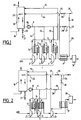
- FIG. 1 shows the main air compressor 1 of an air distillation installation, which may also be of a conventional type, for example with a double distillation column.
- Compressor 1 has three stages 2 to 4 and is associated with four indirect and counter-current type heat exchangers.
- a water cooling circuit associated with the compressor 1 comprises: a pipe 9 for the supply of chilled water, equipped with a circulation pump 10 and from which three branches 11 to 13 start, which lead respectively to the cold end of the exchangers 5 to 7; a pipe 14 for returning hot water, to which three pipes 15 to 17 terminate respectively starting from the hot end of the exchangers 5 to 7; and a cooling tower 18 supplied at the head by line 14 and supplying at its base line 9.
- Tower 18 has at its base an atmospheric air inlet 19 and at its top an outlet 20 for heated and humidified air. It also comprises at its base a purge line 21 provided with a valve 22, and it is equipped with a member 23 for ascending circulation of the refrigerant air.
- a supply water supply pipe 24 connected, via a pump or a water tower (not shown), to a groundwater table.
- This pipe first passes through the exchanger 8, from its cold end to its hot end, then is connected to the tower 18. It further comprises a by-pass 25, provided with a valve 26, at the terminals of the exchanger 8.
- the pipe 9, after its diversion 13, is extended by a section 27 fitted with a valve 28 and ending at a point 29 of the pipe 24 near the cold end of the exchanger 8.
- Another valve 30 is provided in line 24 between bypass 25 and point 29.
- make-up water drawn from a groundwater table is all year round at a relatively stable temperature, for example between +5 and + 15 ° C.
- a relatively stable temperature for example between +5 and + 15 ° C.
- the atmospheric air may be cold enough for the water treated in 18 to be cooled below + 15 ° C, and more precisely to a temperature at least as low as that of the water d 'extra.
- the valve 30 is closed and the valves 26 and 28 are opened.
- the make-up water then directly feeds the tower 18, and it is the circulation water coming from the latter that feeds the exchanger 8 .
- FIG. 2 differs from that of FIG. 1 only by the combination of the exchangers 7 and 8 in a single exchanger 7A, supplied by the pipe 24.
- the compressed air at 4 is directly cooled by the make-up water, before this is sent to the tower 18.
- the air leaving the exchanger 7A is then directly sent to the apparatus 31 for purification by adsorption, as previously.
- the bypass 25 makes it possible, as explained above, to send the make-up water directly to the tower 18 and to cool the exchanger 7A by means of the water circulating in the pipe. 9.
- the variant of the Figure 2 requires a relatively large flow of make-up water to cool the exchanger 7A. If this flow is in excess of the needs of tower 18, we can either increase the purge flow at 21, or send to the sewer, or otherwise evacuate from the installation, the excess make-up water in upstream of tower 18, as shown in dashed line at 32. This remark is also valid for the variant of Figure 1.
- the cooling of a compressed gas by the make-up water of an air cooling tower in one or the other form of implementation described above, can also be applied to the others. compressors for air distillation installations. In fact, in the case of an air blower or a nitrogen compressor of the refrigeration cycle, this cooling mode makes it possible economically to lower the temperature of the compressed gas substantially before it enters the line. the following cryogenic heat exchange. This allows for example to increase the production of liquid.
- the inlet temperature of the compressed gas is thus regulated in the heat exchange line which follows. This applies in particular to the case where, in Figure 1, there would be provided, in addition to the exchanger 8 or another pre-cooling device mounted in place of this exchanger, a water-cooled heat exchanger d 'backup, mounted between the outlet of the cleaning device 31 and the hot end of the main heat exchange line of the air distillation installation.
- Tower 18 can be specifically associated with the compressors to be cooled, or it can be used at the same time to cool cooling water from other devices on the site, for example an arc furnace supplied with oxygen by the installation air distillation.
Landscapes
- Engineering & Computer Science (AREA)
- Physics & Mathematics (AREA)
- Thermal Sciences (AREA)
- Mechanical Engineering (AREA)
- General Engineering & Computer Science (AREA)
- Separation By Low-Temperature Treatments (AREA)
- Devices That Are Associated With Refrigeration Equipment (AREA)
Abstract
Description
- La présente invention est relative à un procédé de compression d'un gaz, du type dans lequel on alimente en eau d'appoint un appareil de réfrigération à l'air de l'eau de refroidissement d'un appareil de compression d'un gaz. Elle s'applique en particulier aux divers appareils de compression que comportent les installations de distillation d'air.
- Dans les installations de distillation d'air, l'air atmosphérique est comprimé vers 6 bars absolus par un compresseur à plusieurs étages. Chaque étage intermédiaire comporte un échangeur de chaleur intermédiaire, dit "réfrigérant inter-étages", et le dernier étage comporte un échangeur de chaleur dit "réfrigérant final". Ces échangeurs sont généralement alimentés par de l'eau qui provient de l'appareil de réfrigération à l'air, lequel traite l'eau de retour des échangeurs.
- Du fait de l'évaporation d'une partie de l'eau dans l'appareil de réfrigération et de la nécessité d'effectuer des purges de déconcentration du circuit, on alimente cet appareil avec un débit d'eau d'appoint, qui provient généralement d'une nappe phréatique.
- L'eau traitée par l'appareil de réfrigération se trouve à une température variable suivant les saisons, fonction de la température de l'air atmosphérique. En saison chaude au moins, elle ne permet généralement pas d'abaisser la température de l'air issu du dernier étage du compresseur au-dessous de +25 à +30°C. Pour optimiser l'appareil d'épuration par adsorption en réduisant la quantité d'absorbant nécessaire, on monte entre le réfrigérant final et l'appareil d'adsorption un groupe frigorifique, ou un autre appareil auxiliaire de refroidissement, afin d'abaisser la température de l'air comprimé, typiquement au-dessous de +15°C.
- Les installations de distillation d'air comportent généralement d'autres appareils de compression, eux aussi refroidis par de l'eau provenant du circuit précité : un surpresseur d'air monté en aval du compresseur principal, généralement couplé à une turbine de détente d'air, et/ou un compresseur d'azote de cycle, Ces appareils de compression refoulent généralement dans des échangeurs de refroidissement cryogénique, et il serait intéressant de prérefroidir de manière plus poussée le gaz qu'ils refoulent, par exemple pour augmenter la production de liquide.
- Or, dans ces appareils de compression comme pour le compresseur d'air principal, l'abaissement de la température du gaz comprimé, en saison chaude au moins, au-dessous de 25°C environ, nécessite l'utilisation d'un groupe frigorifique ou d'un autre appareil auxiliaire, dont le coût d'acquisition et de maintenance n'est pas négligeable.
- L'invention a pour but de permettre d'abaisser la température du gaz comprimé sans avoir recours à un groupe frigorifique ou autre appareil auxiliaire, et ce de manière particulièrement économique.
- A cet effet, l'invention a pour objet un procédé de compression d'un gaz, du type précité, caractérisé en ce que, au moins lorsque l'eau d'appoint est plus froide que l'eau traitée par l'appareil de réfrigération, on met l'eau d'appoint en relation d'échange thermique avec le gaz refoulé par le dernier étage de l'appareil de compression, puis on envoie l'eau d'appoint dans l'appareil de réfrigération.
- Ce procédé peut comporter une ou plusieurs des caractéristiques suivantes :
- on met le gaz refoulé par le dernier étage de l'appareil de compression en relation d'échange thermique d'abord avec de l'eau traitée par l'appareil de réfrigération, puis avec l'eau d'appoint;
- on met le gaz refoulé par le dernier étage de l'appareil de compression directement en relation d'échange thermique avec l'eau d'appoint;
- l'appareil de compression est le compresseur d'air principal d'une installation de distillation d'air, l'air refroidi par l'échange thermique avec l'eau d'appoint étant directement envoyé à un appareil d'épuration d'air par adsorption ou à la ligne d'échange thermique principale de cette installation;
- l'appareil de compression est un surpresseur d'air d'une installation de distillation d'air, l'air refroidi par l'échange thermique avec l'eau d'appoint étant envoyé au bout chaud de la ligne d'échange thermique principale de cette installation;
- l'appareil de compression est un compresseur d'azote de cycle d'une installation de distillation d'air, l'azote refroidi par l'échange thermique avec l'eau d'appoint étant envoyé au bout chaud d'un échangeur thermique de liquéfaction d'azote de cette installation;
- on utilise, pour ledit échange thermique, un débit d'eau d'appoint excédentaire par rapport aux besoins de l'appareil de réfrigération, et on compense l'excès d'eau d'appoint par purge de cet appareil et/ou par évacuation d'eau d'appoint en amont de cet appareil.
- L'invention a également pour objet un ensemble de compression d'un gaz destiné à la mise en oeuvre d'un tel procédé. Cet ensemble, du type comprenant un appareil de compression associé à un circuit de refroidissement à l'eau comprenant un appareil de réfrigération à l'air de l'eau de retour, et une conduite d'alimentation de l'appareil de réfrigération en eau d'appoint, est caractérisé en ce que la conduite d'alimentation en eau d'appoint passe par un échangeur de chaleur monté sur la conduite de refoulement du dernier étage de l'appareil de compression, avant d'atteindre l'appareil de réfrigération.
- Dans un mode de réalisation de cet ensemble de compression, la conduite d'alimentation en eau d'appoint comporte un by-pass sélectif aux bornes dudit échangeur de chaleur, et il est prévu des moyens pour alimenter sélectivement cet échangeur avec de l'eau traitée par l'appareil de réfrigération.
- Des exemples de mise en oeuvre de l'invention vont maintenant être décrits en regard du dessin annexé, sur lequel :
- la Figure 1 représente schématiquement un ensemble de compression d'air conforme à l'invention; et
- la Figure 2 est une vue analogue d'une variante.
- On a représenté à la Figure 1 le compresseur principal d'air 1 d'une installation de distillation d'air, qui peut être par ailleurs d'un type classique, par exemple à double colonne de distillation.
- Le compresseur 1 comporte trois étages 2 à 4 et est associé à quatre échangeurs de chaleur de type indirect et à contre-courant. Un premier réfrigérant inter-étages 5, un second réfrigérant inter-étages 6, un réfrigérant "final" 7, et un échangeur de chaleur de prérefroidissement 8.
- Un circuit de refroidissement à l'eau associé au compresseur 1 comprend : une conduite 9 d'amenée d'eau réfrigérée, équipée d'une pompe de circulation 10 et d'où partent trois dérivations 11 à 13 qui aboutissent respectivement au bout froid des échangeurs 5 à 7; une conduite 14 de retour d'eau chaude, à laquelle aboutissent trois conduites 15 à 17 partant respectivement du bout chaud des échangeurs 5 à 7; et une tour de réfrigération 18 alimentée en tête par la conduite 14 et alimentant à sa base la conduite 9.
- La tour 18 comporte à sa base une entrée d'air atmosphérique 19 et à son sommet une sortie 20 d'air réchauffé et humidifié. Elle comporte également à sa base une conduite de purge 21 munie d'une vanne 22, et elle est équipée d'un organe 23 de mise en circulation ascendante de l'air réfrigérant.
- Le circuit décrit ci-dessus est complété par une conduite 24 d'alimentation en eau d'appoint, reliée, via une pompe ou un château d'eau (non représenté), à une nappe phréatique. Cette conduite traverse d'abord l'échangeur 8, de son bout froid à son bout chaud, puis est reliée à la tour 18. Elle comporte de plus un by-pass 25, muni d'une vanne 26, aux bornes de l'échangeur 8. La conduite 9, après sa dérivation 13, se prolonge par un tronçon 27 équipé d'une vanne 28 et aboutissant à un point 29 de la conduite 24 voisin du bout froid de l'échangeur 8. Une autre vanne 30 est prévue dans la conduite 24 entre le by-pass 25 et le point 29.
- En saison chaude, l'air atmosphérique, à +25 à +30°C par exemple, ne permet pas à la tour 18 de réfrigérer l'eau, suivant l'hygrométrie de l'air, au-dessous de +25 à +35°C environ. L'air comprimé sort donc de l'échangeur 7 vers +30 à +40°C.
- En revanche, l'eau d'appoint soutirée d'une nappe phréatique est toute l'année à une température relativement stable, par exemple comprise entre +5 et +15°C. En circulant d'abord dans l'échangeur 8, elle abaisse donc la température de l'air comprimé jusqu'à +10 à +20°C, ce qui est favorable pour sa dessication-décarbonation par adsorption et permet, au prix d'un simple échangeur de chaleur 8, d'éviter l'utilisation d'un groupe frigorifique ou autre appareil de prérefroidissement en aval de l'échangeur 7. L'air sortant de l'échangeur 8 est ainsi directement envoyé dans l'appareil 31 d'épuration par adsorption.
- L'eau d'appoint ressort de l'échangeur 8 vers +15 à +25°C et alimente ensuite la tour 18, pour compenser l'évaporation d'eau dans celle-ci ainsi que le débit de purge soutiré en 21.
- Il est à noter que l'élévation de température de l'eau d'appoint, par rapport à une solution classique dans laquelle elle alimenterait directement la tour 18, a une influence négligeable sur les performances de cette tour, car son débit ne représente que quelques % du débit total d'eau réfrigérée.
- En saison froide, l'air atmosphérique peut être suffisamment froid pour que l'eau traitée en 18 soit refroidie au-dessous de +15°C, et plus précisément jusqu'à une température au moins aussi basse que celle de l'eau d'appoint. Dans ce cas, on ferme la vanne 30 et on ouvre les vannes 26 et 28. L'eau d'appoint alimente alors directement la tour 18, et c'est l'eau de circulation issue de cette dernière qui alimente l'échangeur 8.
- En variante, on pourrait d'ailleurs se passer du tronçon de conduite 27, puisque, dans un tel cas, l'échangeur 7 fonctionne dans les mêmes conditions que l'échangeur 8.
- La variante de la Figure 2 ne diffère de celle de la Figure 1 que par la réunion des échangeurs 7 et 8 en un seul échangeur 7A, alimenté par la conduite 24. Ainsi, en période chaude, l'air comprimé en 4 est directement refroidi par l'eau d'appoint, avant que celle-ci soit envoyée à la tour 18. L'air sortant de l'échangeur 7A est ensuite directement envoyé à l'appareil 31 d'épuration par adsorption, comme précédemment. Bien entendu, en période froide, le by-pass 25 permet, comme expliqué plus haut, d'envoyer directement l'eau d'appoint à la tour 18 et de refroidir l'échangeur 7A au moyen de l'eau circulant dans la conduite 9.
- Comme on le comprend, la variante de la Figure 2 nécessite un débit relativement important d'eau d'appoint pour refroidir l'échangeur 7A. Si ce débit est excédentaire par rapport aux besoins de la tour 18, on peut soit augmenter le débit de purge en 21, soit envoyer à l'égout, ou évacuer autrement de l'installation, l'excédant d'eau d'appoint en amont de la tour 18, comme illustré en trait mixte en 32. Cette remarque est également valable pour la variante de la Figure 1.
- Le refroidissement d'un gaz comprimé par l'eau d'appoint d'une tour de réfrigération à l'air, sous l'une ou l'autre forme de mise en oeuvre décrite ci-dessus, peut s'appliquer également aux autres appareils de compression des installations de distillation d'air. En effet, dans le cas d'un surpresseur d'air ou d'un compresseur d'azote de cycle frigorifique, ce mode de refroidissement permet de façon économique d'abaisser de façon substantielle la température du gaz comprimé avant son entrée dans la ligne d'échange thermique cryogénique qui suit. Ceci permet par exemple d'augmenter la production de liquide.
- De plus, dans tous les cas, on régularise ainsi la température d'entrée du gaz comprimé dans la ligne d'échange thermique qui suit. Ceci s'applique notamment au cas où, sur la Figure 1, on prévoirait, en supplément de l'échangeur 8 ou d'un autre appareil de préréfrigération monté à la place de cet échangeur, un échangeur de chaleur refroidi par l'eau d'appoint, monté entre la sortie de l'appareil d'épuration 31 et le bout chaud de la ligne d'échange thermique principale de l'installation de distillation d'air.
- La tour 18 peut être spécifiquement associée aux compresseurs à refroidir, ou bien elle peut servir en même temps à réfrigérer de l'eau de refroidissement d'autres appareils du site, par exemple d'un four à arc alimenté en oxygène par l'installation de distillation d'air.
Claims (14)
Applications Claiming Priority (2)
| Application Number | Priority Date | Filing Date | Title |
|---|---|---|---|
| FR9311232A FR2710370B1 (fr) | 1993-09-21 | 1993-09-21 | Procédé et ensemble de compression d'un gaz. |
| FR9311232 | 1993-09-21 |
Publications (2)
| Publication Number | Publication Date |
|---|---|
| EP0644390A1 true EP0644390A1 (fr) | 1995-03-22 |
| EP0644390B1 EP0644390B1 (fr) | 1996-10-23 |
Family
ID=9451074
Family Applications (1)
| Application Number | Title | Priority Date | Filing Date |
|---|---|---|---|
| EP94402025A Expired - Lifetime EP0644390B1 (fr) | 1993-09-21 | 1994-09-12 | Procédé et ensemble de compression d'un gaz |
Country Status (8)
| Country | Link |
|---|---|
| US (1) | US5481880A (fr) |
| EP (1) | EP0644390B1 (fr) |
| JP (1) | JPH07167554A (fr) |
| CN (1) | CN1104617C (fr) |
| CA (1) | CA2132367A1 (fr) |
| DE (1) | DE69400794T2 (fr) |
| ES (1) | ES2094030T3 (fr) |
| FR (1) | FR2710370B1 (fr) |
Cited By (2)
| Publication number | Priority date | Publication date | Assignee | Title |
|---|---|---|---|---|
| FR2988166A1 (fr) * | 2012-03-13 | 2013-09-20 | Air Liquide | Procede et appareil de condensation d'un debit gazeux riche en dioxyde de carbone |
| EP3124902A1 (fr) | 2015-07-28 | 2017-02-01 | Linde Aktiengesellschaft | Installation de décomposition de l'air, procédé de fonctionnement et dispositif de commande |
Families Citing this family (13)
| Publication number | Priority date | Publication date | Assignee | Title |
|---|---|---|---|---|
| FR2815549B1 (fr) * | 2000-10-19 | 2003-01-03 | Air Liquide | Installation et procede de mise a l'air de gaz residuels des unites de distillation ou de liquefaction d'air |
| US20030033831A1 (en) * | 2001-08-15 | 2003-02-20 | Davies Brian M. | System and method of cooling |
| RU2208713C1 (ru) * | 2001-11-09 | 2003-07-20 | Ахмеров Марат Серажетдинович | Способ охлаждения компремируемого воздуха и компрессорная установка |
| US6912859B2 (en) * | 2002-02-12 | 2005-07-05 | Air Liquide Process And Construction, Inc. | Method and apparatus for using a main air compressor to supplement a chill water system |
| AU2003225158A1 (en) * | 2002-04-24 | 2003-11-10 | Praxair Technology, Inc. | Integrated energy recovery system |
| CN1847766A (zh) * | 2005-02-11 | 2006-10-18 | 林德股份公司 | 通过与冷却液体直接热交换而冷却气体的方法和装置 |
| BE1018598A3 (nl) * | 2010-01-25 | 2011-04-05 | Atlas Copco Airpower Nv | Werkwijze voor het recupereren van enrgie. |
| US20120118004A1 (en) * | 2010-11-12 | 2012-05-17 | Exxonmobil Research And Engineering Company | Adsorption chilling for compressing and transporting gases |
| FR2989454A1 (fr) * | 2012-04-16 | 2013-10-18 | Air Liquide | Installation de compression d'un flux gazeux humide |
| CN103343740B (zh) * | 2013-05-27 | 2015-08-12 | 中国五环工程有限公司 | 二氧化碳压缩机的节能降耗方法及其系统 |
| CN105758235B (zh) * | 2016-02-26 | 2018-05-08 | 国网上海市电力公司 | 一种中空板式空气冷却塔及其控制方法 |
| US10888815B2 (en) | 2018-07-27 | 2021-01-12 | Saudi Arabian Oil Company | Drying compressed gas |
| DE102019102387A1 (de) * | 2019-01-30 | 2020-07-30 | Gardner Denver Deutschland Gmbh | Kühlungsanordnung und Verfahren zur Kühlung eines mindestens zweistufigen Drucklufterzeugers |
Citations (3)
| Publication number | Priority date | Publication date | Assignee | Title |
|---|---|---|---|---|
| US3722226A (en) * | 1970-03-25 | 1973-03-27 | Airco Inc | Process gas forecooling system |
| US3851495A (en) * | 1971-10-05 | 1974-12-03 | Computer Sciences Corp | Method and apparatus for preventing thermal pollution |
| DE2550908A1 (de) * | 1975-11-13 | 1977-05-18 | Hochtemperatur Reaktorbau Gmbh | Verfahren zum abfuehren der im kuehlwasserkreislauf von industrieanlagen anfallenden waerme |
Family Cites Families (14)
| Publication number | Priority date | Publication date | Assignee | Title |
|---|---|---|---|---|
| US2333748A (en) * | 1941-06-25 | 1943-11-09 | Hercules Powder Co Ltd | Treatment of chlorine |
| US2708831A (en) * | 1953-04-09 | 1955-05-24 | Air Reduction | Separation of air |
| LU35441A1 (fr) * | 1956-09-25 | |||
| US3094133A (en) * | 1959-07-22 | 1963-06-18 | Earl E Treanor | Chemical feed and blowdown system |
| US3144316A (en) * | 1960-05-31 | 1964-08-11 | Union Carbide Corp | Process and apparatus for liquefying low-boiling gases |
| GB1074550A (en) * | 1964-09-04 | 1967-07-05 | English Electric Co Ltd | Water storage systems for closed steam turbine condensate cooling systems |
| US3677019A (en) * | 1969-08-01 | 1972-07-18 | Union Carbide Corp | Gas liquefaction process and apparatus |
| FR2284848A1 (fr) * | 1974-09-12 | 1976-04-09 | Cem Comp Electro Mec | Perfectionnements apportes aux installations de refrigeration |
| US4054623A (en) * | 1975-09-24 | 1977-10-18 | Michael Ouska | Cooling system |
| US4315404A (en) * | 1979-05-25 | 1982-02-16 | Chicago Bridge & Iron Company | Cooling system, for power generating plant, using split or partitioned heat exchanger |
| JPS5918395A (ja) * | 1982-07-23 | 1984-01-30 | Toshiba Corp | 冷却塔 |
| JPS6093298A (ja) * | 1983-10-27 | 1985-05-25 | Toshiba Corp | 冷却設備 |
| JPS6470635A (en) * | 1987-09-09 | 1989-03-16 | Nec Corp | Cooling water temperature control device |
| US5231835A (en) * | 1992-06-05 | 1993-08-03 | Praxair Technology, Inc. | Liquefier process |
-
1993
- 1993-09-21 FR FR9311232A patent/FR2710370B1/fr not_active Expired - Fee Related
-
1994
- 1994-09-12 EP EP94402025A patent/EP0644390B1/fr not_active Expired - Lifetime
- 1994-09-12 DE DE69400794T patent/DE69400794T2/de not_active Expired - Lifetime
- 1994-09-12 ES ES94402025T patent/ES2094030T3/es not_active Expired - Lifetime
- 1994-09-13 JP JP6218986A patent/JPH07167554A/ja not_active Ceased
- 1994-09-16 US US08/307,001 patent/US5481880A/en not_active Expired - Lifetime
- 1994-09-19 CA CA002132367A patent/CA2132367A1/fr not_active Abandoned
- 1994-09-20 CN CN94115355A patent/CN1104617C/zh not_active Expired - Fee Related
Patent Citations (3)
| Publication number | Priority date | Publication date | Assignee | Title |
|---|---|---|---|---|
| US3722226A (en) * | 1970-03-25 | 1973-03-27 | Airco Inc | Process gas forecooling system |
| US3851495A (en) * | 1971-10-05 | 1974-12-03 | Computer Sciences Corp | Method and apparatus for preventing thermal pollution |
| DE2550908A1 (de) * | 1975-11-13 | 1977-05-18 | Hochtemperatur Reaktorbau Gmbh | Verfahren zum abfuehren der im kuehlwasserkreislauf von industrieanlagen anfallenden waerme |
Cited By (4)
| Publication number | Priority date | Publication date | Assignee | Title |
|---|---|---|---|---|
| FR2988166A1 (fr) * | 2012-03-13 | 2013-09-20 | Air Liquide | Procede et appareil de condensation d'un debit gazeux riche en dioxyde de carbone |
| WO2013135996A3 (fr) * | 2012-03-13 | 2015-06-11 | L'air Liquide, Societe Anonyme Pour L'etude Et L'exploitation Des Procedes Georges Claude | Procédé et appareil de condensation d'un débit gazeux riche en dioxyde de carbone |
| US9797653B2 (en) | 2012-03-13 | 2017-10-24 | L'Air Liquide Société Anonyme Pour L'Étude Et L'Exploitation Des Procedes Georges Claude | Method and device for condensing a carbon dioxide-rich gas stream |
| EP3124902A1 (fr) | 2015-07-28 | 2017-02-01 | Linde Aktiengesellschaft | Installation de décomposition de l'air, procédé de fonctionnement et dispositif de commande |
Also Published As
| Publication number | Publication date |
|---|---|
| CN1104617C (zh) | 2003-04-02 |
| ES2094030T3 (es) | 1997-01-01 |
| CN1104724A (zh) | 1995-07-05 |
| DE69400794D1 (de) | 1996-11-28 |
| JPH07167554A (ja) | 1995-07-04 |
| FR2710370A1 (fr) | 1995-03-31 |
| DE69400794T2 (de) | 1997-02-27 |
| FR2710370B1 (fr) | 1995-12-08 |
| CA2132367A1 (fr) | 1995-03-22 |
| US5481880A (en) | 1996-01-09 |
| EP0644390B1 (fr) | 1996-10-23 |
Similar Documents
| Publication | Publication Date | Title |
|---|---|---|
| EP0644390B1 (fr) | Procédé et ensemble de compression d'un gaz | |
| CA1146724A (fr) | Procede et installation cryogeniques de separation d'air avec production d'oxygene sous haute pression | |
| FR2851330A1 (fr) | Procede et installation de production sous forme gazeuse et sous haute pression d'au moins un fluide choisi parmi l'oxygene, l'argon et l'azote par distillation cryogenique de l'air | |
| EP2185873B1 (fr) | Procédé de réfrigération cryogénique d'un fluide, par exemple d'hélium, destiné à alimenter un consommateur de fluide, ainsi qu'à une installation correspondante | |
| EP0848220B1 (fr) | Procédé et installation de fourniture d'un débit variable d'un gaz de l'air | |
| EP0178207A1 (fr) | Procédé et installation de fractionnement cryogénique de charges gazeuses | |
| FR2775512A1 (fr) | Poste et procede de distribution d'un gaz detendu | |
| EP0718576A1 (fr) | Procédé de séparation d'un mélange gazeux par distillation cryogénique | |
| EP0661505B1 (fr) | Procédé et installation de liquéfaction d'un gaz | |
| FR2805339A1 (fr) | Procede de production d'oxygene par rectification cryogenique | |
| CA2119597A1 (fr) | Procd et installation de production d'oxygne gazeux et/ou d'azote gazeux sous pression par distillation d'air | |
| FR2723184A1 (fr) | Procede et installation de production d'oxygene gazeux sous pression a debit variable | |
| FR2690982A1 (fr) | Procédé et installation de production d'oxygène gazeux impur par distillation d'air. | |
| EP0654643A1 (fr) | Procédé et installation de distillation d'air | |
| WO2013079856A1 (fr) | Procédé et appareil de réchauffage de l'azote destiné à régénérer une unité d'adsorption d'une unité de séparation d'air | |
| EP0914584B1 (fr) | Procede et installation de production d'un gaz de l'air a debit variable | |
| EP0952415A1 (fr) | Procédé et installation de distillation d'air avec production variable d'argon | |
| EP1219910A1 (fr) | Procédé d'alimentation en air d'au moins une unité à turbine à gaz et d'au moins une unité de distillation d'air, et installation de mise en oeuvre | |
| FR2489477A1 (fr) | Procede d'exploitation de dispositifs de compression de gaz | |
| EP0422973A1 (fr) | Procédé et installation de réfrigeration utilisant un mélange réfrigerant | |
| FR3121744A3 (fr) | Module à incorporer dans une installation de distillation d’air | |
| WO2003006902A1 (fr) | Procede et installation de production de vapeur d'eau et de distillation d'air | |
| FR2685460A1 (fr) | Procede et installation de production d'oxygene gazeux sous pression par distillation d'air. | |
| EP4589232A1 (fr) | Procédé et appareil de compression d'un gaz | |
| FR2842589A1 (fr) | Procede et installation de separation d'air par distillation cryogenique |
Legal Events
| Date | Code | Title | Description |
|---|---|---|---|
| PUAI | Public reference made under article 153(3) epc to a published international application that has entered the european phase |
Free format text: ORIGINAL CODE: 0009012 |
|
| 17P | Request for examination filed |
Effective date: 19940915 |
|
| AK | Designated contracting states |
Kind code of ref document: A1 Designated state(s): DE ES FR GB IT |
|
| GRAG | Despatch of communication of intention to grant |
Free format text: ORIGINAL CODE: EPIDOS AGRA |
|
| GRAH | Despatch of communication of intention to grant a patent |
Free format text: ORIGINAL CODE: EPIDOS IGRA |
|
| 17Q | First examination report despatched |
Effective date: 19960328 |
|
| GRAH | Despatch of communication of intention to grant a patent |
Free format text: ORIGINAL CODE: EPIDOS IGRA |
|
| GRAA | (expected) grant |
Free format text: ORIGINAL CODE: 0009210 |
|
| AK | Designated contracting states |
Kind code of ref document: B1 Designated state(s): DE ES FR GB IT |
|
| ITF | It: translation for a ep patent filed | ||
| REF | Corresponds to: |
Ref document number: 69400794 Country of ref document: DE Date of ref document: 19961128 |
|
| GBT | Gb: translation of ep patent filed (gb section 77(6)(a)/1977) |
Effective date: 19961122 |
|
| REG | Reference to a national code |
Ref country code: ES Ref legal event code: FG2A Ref document number: 2094030 Country of ref document: ES Kind code of ref document: T3 |
|
| PLBI | Opposition filed |
Free format text: ORIGINAL CODE: 0009260 |
|
| PLBF | Reply of patent proprietor to notice(s) of opposition |
Free format text: ORIGINAL CODE: EPIDOS OBSO |
|
| 26 | Opposition filed |
Opponent name: LINDE AKTIENGESELLSCHAFT Effective date: 19970723 |
|
| PLBF | Reply of patent proprietor to notice(s) of opposition |
Free format text: ORIGINAL CODE: EPIDOS OBSO |
|
| PLBO | Opposition rejected |
Free format text: ORIGINAL CODE: EPIDOS REJO |
|
| PLBN | Opposition rejected |
Free format text: ORIGINAL CODE: 0009273 |
|
| STAA | Information on the status of an ep patent application or granted ep patent |
Free format text: STATUS: OPPOSITION REJECTED |
|
| 27O | Opposition rejected |
Effective date: 19980406 |
|
| REG | Reference to a national code |
Ref country code: GB Ref legal event code: IF02 |
|
| PGFP | Annual fee paid to national office [announced via postgrant information from national office to epo] |
Ref country code: ES Payment date: 20100923 Year of fee payment: 17 |
|
| PGFP | Annual fee paid to national office [announced via postgrant information from national office to epo] |
Ref country code: FR Payment date: 20101005 Year of fee payment: 17 |
|
| PGFP | Annual fee paid to national office [announced via postgrant information from national office to epo] |
Ref country code: GB Payment date: 20100921 Year of fee payment: 17 |
|
| PGFP | Annual fee paid to national office [announced via postgrant information from national office to epo] |
Ref country code: DE Payment date: 20100922 Year of fee payment: 17 |
|
| PGFP | Annual fee paid to national office [announced via postgrant information from national office to epo] |
Ref country code: IT Payment date: 20100928 Year of fee payment: 17 |
|
| GBPC | Gb: european patent ceased through non-payment of renewal fee |
Effective date: 20110912 |
|
| PG25 | Lapsed in a contracting state [announced via postgrant information from national office to epo] |
Ref country code: IT Free format text: LAPSE BECAUSE OF NON-PAYMENT OF DUE FEES Effective date: 20110912 |
|
| REG | Reference to a national code |
Ref country code: FR Ref legal event code: ST Effective date: 20120531 |
|
| REG | Reference to a national code |
Ref country code: DE Ref legal event code: R119 Ref document number: 69400794 Country of ref document: DE Effective date: 20120403 |
|
| PG25 | Lapsed in a contracting state [announced via postgrant information from national office to epo] |
Ref country code: DE Free format text: LAPSE BECAUSE OF NON-PAYMENT OF DUE FEES Effective date: 20120403 |
|
| PG25 | Lapsed in a contracting state [announced via postgrant information from national office to epo] |
Ref country code: GB Free format text: LAPSE BECAUSE OF NON-PAYMENT OF DUE FEES Effective date: 20110912 Ref country code: FR Free format text: LAPSE BECAUSE OF NON-PAYMENT OF DUE FEES Effective date: 20110930 |
|
| REG | Reference to a national code |
Ref country code: ES Ref legal event code: FD2A Effective date: 20130604 |
|
| PG25 | Lapsed in a contracting state [announced via postgrant information from national office to epo] |
Ref country code: ES Free format text: LAPSE BECAUSE OF NON-PAYMENT OF DUE FEES Effective date: 20110913 |