EP0643375B1 - Door chime assembly - Google Patents
Door chime assembly Download PDFInfo
- Publication number
- EP0643375B1 EP0643375B1 EP94302933A EP94302933A EP0643375B1 EP 0643375 B1 EP0643375 B1 EP 0643375B1 EP 94302933 A EP94302933 A EP 94302933A EP 94302933 A EP94302933 A EP 94302933A EP 0643375 B1 EP0643375 B1 EP 0643375B1
- Authority
- EP
- European Patent Office
- Prior art keywords
- walls
- wall
- rear plate
- set forth
- door chime
- Prior art date
- Legal status (The legal status is an assumption and is not a legal conclusion. Google has not performed a legal analysis and makes no representation as to the accuracy of the status listed.)
- Expired - Lifetime
Links
- 239000004743 Polypropylene Substances 0.000 claims description 4
- 239000004033 plastic Substances 0.000 claims description 4
- 229920003023 plastic Polymers 0.000 claims description 4
- -1 polypropylene Polymers 0.000 claims description 4
- 229920001155 polypropylene Polymers 0.000 claims description 4
- 239000000463 material Substances 0.000 description 3
- 230000008901 benefit Effects 0.000 description 2
- 238000001746 injection moulding Methods 0.000 description 2
- 238000007789 sealing Methods 0.000 description 2
- 238000010276 construction Methods 0.000 description 1
- 238000002347 injection Methods 0.000 description 1
- 239000007924 injection Substances 0.000 description 1
- 238000000034 method Methods 0.000 description 1
- 239000000203 mixture Substances 0.000 description 1
- 238000012986 modification Methods 0.000 description 1
- 230000004048 modification Effects 0.000 description 1
- 239000000454 talc Substances 0.000 description 1
- 229910052623 talc Inorganic materials 0.000 description 1
Images

Classifications
-
- G—PHYSICS
- G10—MUSICAL INSTRUMENTS; ACOUSTICS
- G10K—SOUND-PRODUCING DEVICES; METHODS OR DEVICES FOR PROTECTING AGAINST, OR FOR DAMPING, NOISE OR OTHER ACOUSTIC WAVES IN GENERAL; ACOUSTICS NOT OTHERWISE PROVIDED FOR
- G10K1/00—Devices in which sound is produced by striking a resonating body, e.g. bells, chimes or gongs
- G10K1/06—Devices in which sound is produced by striking a resonating body, e.g. bells, chimes or gongs the resonating devices having the shape of a bell, plate, rod, or tube
- G10K1/062—Devices in which sound is produced by striking a resonating body, e.g. bells, chimes or gongs the resonating devices having the shape of a bell, plate, rod, or tube electrically operated
- G10K1/066—Devices in which sound is produced by striking a resonating body, e.g. bells, chimes or gongs the resonating devices having the shape of a bell, plate, rod, or tube electrically operated the sounding member being a tube, plate or rod
Definitions
- This invention relates to a door chime assembly.
- Door chimes are well known in the art and typically include a chime base holding one or more tone bars and a striking means to strike the tone bars, which vibrate with a predetermined tone.
- Conventional chime bases also include one or more sound or resonance chambers which amplify the tone bar vibration.
- Conventional door chime bases, particularly the sound or resonance chambers are typically made of several component parts, which require handling and assembly. Even for chime bases made by injection molding, as disclosed in DE-B-1257040 and equivalent GB-A-958038 of March 3rd 1965 cited in the examination of this application, a separate piece is necessary to enclose each sound chamber. These extra pieces add to the amount of handling required to assemble each door chime.
- DE-B-1257040 discloses a door chime assembly comprising a one-piece chime base including a rear plate and a plurality of walls integrally formed with the plate which walls define with a separate sealing plate cemented thereto a resonance chamber; a tone bar positioned within said resonance chamber and electrically operably striking means mounted on said chime base for striking said tone bar and causing it to vibrate.
- One object of the invention is to reduce the number of component parts required to assemble a door chime, particularly by reducing the number of component parts in the door chime base.
- the present invention provides a door chime assembly comprising:
- another one of said walls is secured to said rear plate and said one of said walls or a portion thereof is pivotable between a first position in which it extends at an angle to said another wall and a second position in which it extends substantially parallel to said another wall, and said assembly further comprises clasp means acting between said one wall and said another wall for maintaining said one wall in said second position.
- the above-mentioned one wall may comprise two portions at right angles to each other, wherein one of said portions is pivotally attached to said rear plate and an edge of the other of said portions is adjacent said another wall when said one wall is in said second position, and said clasp means may comprise straps pivotally attached to one of said other portion and said another wall and projections engageable with said straps secured to the other of said other portion and said another wall.
- a first one of said plurality of walls is secured to said rear plate and extends substantially perpendicular thereto, a second one of said walls being pivotally attached to said rear plate by a hinge and in spaced relation to said first one of said walls and extending from said rear plate to said first one of said walls, and a pair of spaced third walls secured to said rear plate at an angle to said first one of said walls and extending from said second one of said walls to said first one of said walls to provide said resonance chamber, said second one of said walls being movable from a first position in which it extends at an angle to said first one of said walls to a second position in which an edge thereof is adjacent to said first one of said walls.
- the assembly as defined in the last preceding paragraph further comprises clasp means acting between said second one of said walls and said first one of said walls for maintaining said second wall in said second position.
- said second one of said walls comprises two portions at right angles to each other, wherein one of said portions is pivotally attached to said rear plate and an edge of the other of said portions is adjacent said first one of said walls when said second wall is in said second position, and wherein clasp means comprises straps pivotally attached to one of said other portion and said first wall and projections engageable with said straps secured to the other of said other portion and said first wall.
- the assembly may further comprise at least one dowel support within said chamber and attached to one of said walls of said resonance chamber for supporting said tone bar.
- the assembly may further comprise grommet means around said dowel support and engaging said tone bar to allow relatively free vibration of said tone bar.
- said one of said walls faces another of said walls and said dowel support extends substantially from said one wall to said other wall whereby said tone bar is prevented from falling off said dowel.
- a wall of said resonance chamber includes at least one opening to allow said striking means to strike said tone bar.
- said chime base includes a further plurality of walls defining a further resonance chamber spaced from the first-mentioned said resonance chamber, said further resonance chamber having a wall thereof attached to said rear plate by a hinge and housing a tone bar, and said striking means is adapted to strike either of said tone bars.
- the above-mentioned hinge may be a living hinge.
- the chime base may be made of plastics, for example a polypropylene.
- the illustrated door chime assembly 1 includes a base portion 2 which is illustrated in FIGS. 1 and 2 in an assembled state without a decorative cover.
- Door chime base portion 2 includes a rear plate 3 having mounting holes 4 to secure said base 2, and hence, said assembly 1, to a wall.
- Base portion 2 also includes a pair of resonance chambers 5 and 5a, forming an integral part with said rear plate 3.
- a conventional solenoid, or strike means 6 is secured to said rear plate 3 adjacent said resonance chambers 5 and 5a.
- a pair of opposed resonance chambers 5 and 5a are shown with said solenoid means 6 secured between them.
- the door chime assembly 1 with two chime bars 9 and 9a, two of which are struck by a first electromagnetically movable rod when a first door button, e.g. a front door button, is operated and one of which is struck by a second electromagnetically movable rod when a second door button, e.g., a back door button is operated.
- Each strike rod is movable by separate, electrically energizable solenoids.
- Solenoid means 6 includes one or more strike rods 7 and 7a, each situated within an electrically energizable solenoid 8 (only one of which is schematically shown in FIG.
- tone bar 9 or 9a vibrates within said resonance chamber 5 at said predetermined tone.
- each resonance chamber 5 and 5a in addition to inner walls 11 and 11a, includes walls comprising outer wall portions 12 and 12a and top wall portions 13 and 13a at right angles thereto, a bottom wall 14 and 14a (portions of the plate 3), a front wall 15 and 15a and a back wall 16 and 16a, where the front walls and back walls being integral with the respective walls 11 and ha.
- each of the walls is, preferably, attached to one another, forming a simple-to-assemble one-piece door chime base portion 2.
- the walls comprising wall portions 12 and 12a and wall portions 13 and 13a are connected to said bottom walls 14 and 14a, i.e. the rear plate 3, by line or living hinges 17 and 17a, which form a flexible bridge of material between said outer wall portions 12 and 12a and rear plate 3 (bottom walls 14 and 14a), pivotably joining said outer wall portions 12 and 12a to rear plate 3 along the junctures 18 and 18a between them, as shown in FIG. 3.
- Living hinges 17 and 17a are preferably made of the same material as said door chime base portion 2, but are sufficiently thinned so that the living hinges 17 and 17a bend, allowing the walls comprising wall portions 12, 12a, and 13, 13a to fold over and contact inner walls 11 and 11a, respectively.
- suitable materials for both base 2 and living hinges 17 and 17a include polypropylene and compositions of polypropylene including up to 20% of talc.
- a pair of clasp means comprising straps 19 and 19a, which are preferably secured to said wall portions 13 and 13a, respectively, by living hinges 20 and 20a, which allow the straps 19 and 19a to also be injection molded as a component part of the one-piece chime base portion 2 described above.
- the straps 19 and 19a shown bent back in FIG. 3, include slotted portions 21 and 21a, respectively, which upon closing of the resonance chambers 5 and 5a, as shown in FIGS. 1 and 2, engage one of a pair of corresponding projections 22 and 22a secured along the exterior of the inner side walls 11 and 11a of the resonance chambers 5 and 5a.
- the clasp means 19 and 22, or 19a and 22a firmly secures said resonance chambers 5 and 5a in place. It should be understood that other clasp means may be employed to secure said chambers 5 and 5a.
- Tone bars 9 and 9a rest within said tone resonance chambers 5 and 5a, respectively, on a pair of dowel supports 23, which have pins 24 and 24a passing through holes 9b in said bars 9 and 9a.
- the length of said dowel support 23 is so selected that upon assembly said tone bars 9 and 9a are centrally and securely situated within said tone resonance chambers 5 and 5a, respectively.
- rubber grommets 25 are interposed between the pins 24 and 24a and the tone bars 9 and 9a.
- the grommets 25 preferably also extend slightly outwards beyond the faces of the tone bars 9 and 9a to further cushion the bars 9 and 9a from the dowel supports 23 and 23a and wedge members 26 and 26a affixed to the inside surfaces of said inner side walls 11 and 11a.
- Wedge members 26 and 26a have a sufficient thickness to engage said grommets 25 and thereby prevent said tone bars 9 and 9a from falling off the pins 24 and 24a during transit and handling of the chime assembly.
- a decorative cover may overlie the door chime assembly 1 to cover the solenoid means 6 and chambers 5 and 5a with a more aesthetic front.
- the decorative cover should include a plurality of holes or slots to transmit the resonating sounds produced therein and alert persons adjacent the place where the chime assembly is installed I
- the entire door chime base portion including rear support 3, resonance chambers 5 and 5a, clasps 19 and 19a, and living hinges 17, 17a, 20 and 20a, is made of one piece, eliminating a variety of separate component parts and reducing the amount of handling and assembly required, particularly in constructing or adding the tone resonance chambers 5 and 5a.
- a further benefit of the foregoing construction is that the tone bars 9 and 9a are prevented from falling off the pins 24 and 24a and thus, do not become loose or misaligned during shipping.
Landscapes
- Engineering & Computer Science (AREA)
- Acoustics & Sound (AREA)
- Multimedia (AREA)
- Physics & Mathematics (AREA)
- Securing Of Glass Panes Or The Like (AREA)
- Electromechanical Clocks (AREA)
- Door And Window Frames Mounted To Openings (AREA)
- Blow-Moulding Or Thermoforming Of Plastics Or The Like (AREA)
- Refrigerator Housings (AREA)
- Pivots And Pivotal Connections (AREA)
- Developing Agents For Electrophotography (AREA)
- Saccharide Compounds (AREA)
- Devices For Conveying Motion By Means Of Endless Flexible Members (AREA)
- Vehicle Interior And Exterior Ornaments, Soundproofing, And Insulation (AREA)
- Joining Of Building Structures In Genera (AREA)
- Table Devices Or Equipment (AREA)
Abstract
Description
- This invention relates to a door chime assembly.
- Door chimes are well known in the art and typically include a chime base holding one or more tone bars and a striking means to strike the tone bars, which vibrate with a predetermined tone. Conventional chime bases also include one or more sound or resonance chambers which amplify the tone bar vibration. Conventional door chime bases, particularly the sound or resonance chambers, are typically made of several component parts, which require handling and assembly. Even for chime bases made by injection molding, as disclosed in DE-B-1257040 and equivalent GB-A-958038 of March 3rd 1965 cited in the examination of this application, a separate piece is necessary to enclose each sound chamber. These extra pieces add to the amount of handling required to assemble each door chime.
- DE-B-1257040 discloses a door chime assembly comprising a one-piece chime base including a rear plate and a plurality of walls integrally formed with the plate which walls define with a separate sealing plate cemented thereto a resonance chamber; a tone bar positioned within said resonance chamber and electrically operably striking means mounted on said chime base for striking said tone bar and causing it to vibrate.
- DE-U-1877406 of August 8th 1963, also cited during the examination of this application, discloses an assembly comprising a manually actuated bell housed in box formed by folding of a single piece of cardboard.
- One object of the invention is to reduce the number of component parts required to assemble a door chime, particularly by reducing the number of component parts in the door chime base.
- The present invention provides a door chime assembly comprising:
- a one-piece chime base including a rear plate and a plurality of walls secured to said plate and defining a resonance chamber,
- a tone bar housed within said resonance chamber; and
- electrically operable striking means mounted on said chime base for striking said tone bar and causing it to vibrate, said door chime assembly being characterised in that at least one of said walls is pivotally attached to said rear plate by a hinge.
-
- Preferably, in said assembly defined in the last preceding paragraph another one of said walls is secured to said rear plate and said one of said walls or a portion thereof is pivotable between a first position in which it extends at an angle to said another wall and a second position in which it extends substantially parallel to said another wall, and said assembly further comprises clasp means acting between said one wall and said another wall for maintaining said one wall in said second position.
- The above-mentioned one wall may comprise two portions at right angles to each other, wherein one of said portions is pivotally attached to said rear plate and an edge of the other of said portions is adjacent said another wall when said one wall is in said second position, and said clasp means may comprise straps pivotally attached to one of said other portion and said another wall and projections engageable with said straps secured to the other of said other portion and said another wall.
- Preferably, in the door chime assembly as defined in the last but two paragraph, a first one of said plurality of walls is secured to said rear plate and extends substantially perpendicular thereto, a second one of said walls being pivotally attached to said rear plate by a hinge and in spaced relation to said first one of said walls and extending from said rear plate to said first one of said walls, and a pair of spaced third walls secured to said rear plate at an angle to said first one of said walls and extending from said second one of said walls to said first one of said walls to provide said resonance chamber, said second one of said walls being movable from a first position in which it extends at an angle to said first one of said walls to a second position in which an edge thereof is adjacent to said first one of said walls.
- The assembly as defined in the last preceding paragraph further comprises clasp means acting between said second one of said walls and said first one of said walls for maintaining said second wall in said second position.
- Preferably, said second one of said walls comprises two portions at right angles to each other, wherein one of said portions is pivotally attached to said rear plate and an edge of the other of said portions is adjacent said first one of said walls when said second wall is in said second position, and wherein clasp means comprises straps pivotally attached to one of said other portion and said first wall and projections engageable with said straps secured to the other of said other portion and said first wall.
- The assembly may further comprise at least one dowel support within said chamber and attached to one of said walls of said resonance chamber for supporting said tone bar.
- The assembly may further comprise grommet means around said dowel support and engaging said tone bar to allow relatively free vibration of said tone bar.
- Preferably said one of said walls faces another of said walls and said dowel support extends substantially from said one wall to said other wall whereby said tone bar is prevented from falling off said dowel.
- Preferably a wall of said resonance chamber includes at least one opening to allow said striking means to strike said tone bar.
- In a preferred embodiment described hereinafter said chime base includes a further plurality of walls defining a further resonance chamber spaced from the first-mentioned said resonance chamber, said further resonance chamber having a wall thereof attached to said rear plate by a hinge and housing a tone bar, and said striking means is adapted to strike either of said tone bars.
- The above-mentioned hinge may be a living hinge.
- The chime base may be made of plastics, for example a polypropylene.
- In order that the invention may be well understood, the above-mentioned preferred embodiment thereof which is given by way of example only, will now be described in more detail with reference to the accompanying drawings, in which:
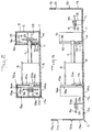
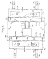
- FIG. 1 is a top view, partly in section, of a door chime assembly comprising a door chime base, tone bars and striking means;
- FIG. 2 is an end elevation view, partly in section, of the assembly shown in Fig. 1;
- FIG. 3 is a top view of the assembly of FIGS. 1 and 2 prior to completion; and
- FIG. 4 is an end elevation view, partly in section, of the assembly shown in FIG. 3 prior to completion.
-
- With reference to FIGS. 1 - 4, the illustrated door chime assembly 1 includes a base portion 2 which is illustrated in FIGS. 1 and 2 in an assembled state without a decorative cover. Door chime base portion 2 includes a
rear plate 3 having mounting holes 4 to secure said base 2, and hence, said assembly 1, to a wall. Base portion 2 also includes a pair ofresonance chambers rear plate 3. A conventional solenoid, or strike means 6 is secured to saidrear plate 3 adjacent saidresonance chambers opposed resonance chambers - Although not required in accordance with principles of the invention, it is conventional to provide the door chime assembly 1 with two
chime bars 9 and 9a, two of which are struck by a first electromagnetically movable rod when a first door button, e.g. a front door button, is operated and one of which is struck by a second electromagnetically movable rod when a second door button, e.g., a back door button is operated. Each strike rod is movable by separate, electrically energizable solenoids. Solenoid means 6 includes one ormore strike rods strike rod tone bar 9 or 9a, as shown in FIGS. 1 and 2, causing therespective tone bar 9 or 9a to vibrate at a predetermined tone. Conventional chimes typically place saidresonance chambers tone bars 9 and 9a to amplify the sound.Strike rods slots inner walls 11 and 11a of saidresonance chambers inner walls 11 and 11a face said solenoid means 6. When struck by saidstrike rod tone bar 9 or 9a vibrates within saidresonance chamber 5 at said predetermined tone. - As shown in FIGS. 1 and 2, each
resonance chamber inner walls 11 and 11a, includes walls comprisingouter wall portions top wall portions bottom wall 14 and 14a (portions of the plate 3), afront wall back wall respective walls 11 and ha. As shown in FIGS. 3 and 4, instead of theresonance chambers - The walls comprising
wall portions wall portions bottom walls 14 and 14a, i.e. therear plate 3, by line orliving hinges outer wall portions bottom walls 14 and 14a), pivotably joining saidouter wall portions rear plate 3 along thejunctures 18 and 18a between them, as shown in FIG. 3.Living hinges living hinges wall portions inner walls 11 and 11a, respectively. Although other plastics can be used, suitable materials for both base 2 andliving hinges junctures 18 and 18a withliving hinges resonance chambers chambers living hinges junctures 18 and 18a with a plurality of short hinge sections along the junctures. - Attached to said
wall portions means comprising straps wall portions living hinges 20 and 20a, which allow thestraps straps portions resonance chambers corresponding projections inner side walls 11 and 11a of theresonance chambers resonance chambers said chambers -
Tone bars 9 and 9a rest within saidtone resonance chambers pins bars 9 and 9a. Preferably, the length of saiddowel support 23 is so selected that upon assembly saidtone bars 9 and 9a are centrally and securely situated within saidtone resonance chambers stricken tone bars 9 and9a rubber grommets 25 are interposed between thepins tone bars 9 and 9a. Thegrommets 25 preferably also extend slightly outwards beyond the faces of thetone bars 9 and 9a to further cushion thebars 9 and 9a from the dowel supports 23 and 23a andwedge members 26 and 26a affixed to the inside surfaces of saidinner side walls 11 and 11a. Wedgemembers 26 and 26a have a sufficient thickness to engage saidgrommets 25 and thereby prevent saidtone bars 9 and 9a from falling off thepins - A decorative cover (not shown) may overlie the door chime assembly 1 to cover the solenoid means 6 and
chambers - As will be appreciated from the foregoing in the embodiment as illustrated in FIGS. 1 - 4, the entire door chime base portion, including
rear support 3,resonance chambers clasps living hinges tone resonance chambers tone bars 9 and 9a are prevented from falling off thepins - It should be understood that although a pair of
resonance chambers - Although a preferred embodiment of the present invention has been described and illustrated, it will be apparent to those skilled in the art that various modifications may be made without departing from the scope of the appended claims.
Claims (14)
- A door chime assembly (1) comprising:a one-piece chime base (2) including a rear plate (3) and a plurality of walls (11,12-13,15,16) secured to said plate and defining a resonance chamber (5),a tone bar (9) housed within said resonance chamber (5); andelectrically operable striking means (6) mounted on said chime base for striking said tone bar and causing it to vibrate, said door chime assembly being characterised in that at least one of said walls (12-13) is pivotally attached to said rear plate (3) by a hinge (17).
- A door chime assembly as set forth in claim 1, wherein another one (11) of said walls is secured to said rear plate, wherein said one (12-13) of said walls or a portion (12) thereof is pivotable between a first position in which it extends at an angle to said another wall (11) and a second position in which it extends substantially parallel to said another wall (11), and further comprising clasp means (19) acting between said one wall (12-13) and said another wall (11) for maintaining said one wall in said second position.
- A door chime assembly as set forth in claim 2, wherein said one wall comprises two portions (12,13) at right angles to each other, wherein one (12) of said portions is pivotally attached to said rear plate and an edge of the other (13) of said portions is adjacent said another wall (11) when said one wall is in said second position, and wherein said clasp means comprises straps (19) pivotally attached to one of said other portion (13) and said another wall (11) and projections (22) engageable with said straps secured to the other of said other portion and said another wall.
- A door chime assembly as claimed in claim 1, wherein a first one (11) of said plurality of walls is secured to said rear plate (3) and extends substantially perpendicular thereto, a second one (12 - 13) of said walls being pivotally attached to said rear plate by a hinge (17) and in spaced relation to said first one (11) of said walls and extending from said rear plate to said first one of said walls, and a pair of spaced third walls (15, 16) secured to said rear plate at an angle to said first one (11) of said walls and extending from said second one (12-13) of said walls to said first one of said walls to provide said resonance chambers (5), said second one of said walls being movable from a first position in which it extends at an angle to said first one of said walls to a second position in which an edge thereof is adjacent to said first one of said walls.
- A door chime assembly as set forth in claim 4, further comprising clasp means (19) acting between said second one (12-13) of said walls and said first one (11) of said walls for maintaining said second wall in said second position.
- A a door chime assembly as set forth in claim 5, wherein said second one of said walls comprises two portions (12, 13) at right angles to each other, wherein one (12) of said portions is pivotally attached to said rear plate (3) and an edge of the other (13) of said portions is adjacent said first one (11) of said walls when said second wall is in said second position, and wherein said clasp means comprises straps (19) pivotally attached to one of said other portion (13) and said first wall (11) and projections (22) engageable with said straps secured to the other of said other portion and said first wall.
- A door chime assembly as set forth in any one of claims 1 to 6, further comprising at least one dowel support (23) within said chamber (25) and attached to one of said walls (12) of said resonance chamber for supporting said tone bar (9).
- A door chime assembly as set forth in claim 7, further comprising grommet means (25) around said dowel support (23) and engaging said tone bar (9) to allow relatively free vibration of said tone bar.
- A door chime assembly as set forth in claim 8, wherein said one of said walls faces another (11) of said walls and wherein said dowel support (23) extends substantially from said one wall to said other wall (11) whereby said tone bar is prevented from falling off said dowel.
- A door chime assembly as set forth in any one of claims 1 to 9, wherein a wall (11) of said resonance chamber (5) includes at least one opening (10) to allow said striking means (6) to strike said tone bar (9).
- A door chime assembly as set forth in any one of claims 1 to 10, wherein said chime base includes a further plurality of walls defining a further resonance chamber (5a) spaced from the first-mentioned said resonance chamber (5), said further resonance chamber having a wall (12-13) thereof attached to said rear plate by a hinge (17a) and housing a tone bar (9a), and wherein said striking means (6) is adapted to strike either of said tone bars.
- A door chime assembly as set forth in any one of claims 1 to 11, wherein said hinge is a living hinge.
- A door chime assembly as set forth in any one of claims 1 to 12, wherein said chime base is made of plastics.
- A door chime assembly as set forth in claim 13, wherein said plastics is a polypropylene.
Priority Applications (1)
| Application Number | Priority Date | Filing Date | Title |
|---|---|---|---|
| EP99102629A EP0919986A3 (en) | 1993-07-14 | 1994-04-25 | Door chime assembly |
Applications Claiming Priority (2)
| Application Number | Priority Date | Filing Date | Title |
|---|---|---|---|
| US91330 | 1993-07-14 | ||
| US08/091,330 US5420564A (en) | 1993-07-14 | 1993-07-14 | Door chime assembly |
Related Child Applications (1)
| Application Number | Title | Priority Date | Filing Date |
|---|---|---|---|
| EP99102629A Division EP0919986A3 (en) | 1993-07-14 | 1994-04-25 | Door chime assembly |
Publications (2)
| Publication Number | Publication Date |
|---|---|
| EP0643375A1 EP0643375A1 (en) | 1995-03-15 |
| EP0643375B1 true EP0643375B1 (en) | 2000-07-05 |
Family
ID=22227220
Family Applications (2)
| Application Number | Title | Priority Date | Filing Date |
|---|---|---|---|
| EP94302933A Expired - Lifetime EP0643375B1 (en) | 1993-07-14 | 1994-04-25 | Door chime assembly |
| EP99102629A Withdrawn EP0919986A3 (en) | 1993-07-14 | 1994-04-25 | Door chime assembly |
Family Applications After (1)
| Application Number | Title | Priority Date | Filing Date |
|---|---|---|---|
| EP99102629A Withdrawn EP0919986A3 (en) | 1993-07-14 | 1994-04-25 | Door chime assembly |
Country Status (8)
| Country | Link |
|---|---|
| US (1) | US5420564A (en) |
| EP (2) | EP0643375B1 (en) |
| CN (1) | CN1043095C (en) |
| AT (1) | ATE194434T1 (en) |
| CA (1) | CA2122426C (en) |
| DE (1) | DE69425099T2 (en) |
| DK (1) | DK0643375T3 (en) |
| MX (1) | MX9404405A (en) |
Families Citing this family (3)
| Publication number | Priority date | Publication date | Assignee | Title |
|---|---|---|---|---|
| US6750760B2 (en) * | 2001-11-15 | 2004-06-15 | Broan-Nutone | Door chime assembly and method |
| USD541689S1 (en) | 2005-01-13 | 2007-05-01 | Broan-Nutone Llc | Doorbell chime cover |
| USD567692S1 (en) | 2005-01-13 | 2008-04-29 | Broan-Nutone Llc | Display doorbell chime cover |
Family Cites Families (13)
| Publication number | Priority date | Publication date | Assignee | Title |
|---|---|---|---|---|
| US2486680A (en) * | 1949-11-01 | Chime | ||
| US2245453A (en) * | 1940-04-15 | 1941-06-10 | A E Rittenhouse Co Inc | Signal device |
| US2265815A (en) * | 1940-12-24 | 1941-12-09 | A E Rittenhouse Co Inc | Chime signal |
| US2972138A (en) * | 1957-08-01 | 1961-02-14 | Carey Philip Mfg Co | Repeater door chimes |
| GB985038A (en) * | 1961-03-01 | 1965-03-03 | V & E Friedland Ltd | Improvements in or relating to electrical signalling devices |
| DE1257040B (en) * | 1961-03-01 | 1967-12-21 | V & E Friedland Ltd | Electric gong bell mechanism |
| DE1877406U (en) * | 1963-06-11 | 1963-08-08 | H C Koenig Fa | TABLE BELL WITH CONTAINER. |
| FR1394992A (en) * | 1964-02-27 | 1965-04-09 | Calor App Electro Domestiques | Door chimes or the like |
| US3973692A (en) * | 1973-08-23 | 1976-08-10 | Nosco Plastics, Inc. | Injection molded folding box |
| DE2716427C3 (en) * | 1977-04-14 | 1980-01-17 | Eichhoff-Werke Gmbh, 5880 Luedenscheid | Electroacoustic gong bell mechanism |
| EP0414821A4 (en) * | 1988-02-17 | 1991-08-07 | Custom Plastics | Container movable from flat to channel-shaped configuration |
| GB2243145B (en) * | 1990-04-05 | 1993-09-22 | Ryford Ltd | Container |
| US5127537A (en) * | 1991-06-05 | 1992-07-07 | Graham Donald R | Tissue cassette with a living hinge |
-
1993
- 1993-07-14 US US08/091,330 patent/US5420564A/en not_active Expired - Lifetime
-
1994
- 1994-04-25 DE DE69425099T patent/DE69425099T2/en not_active Expired - Fee Related
- 1994-04-25 DK DK94302933T patent/DK0643375T3/en active
- 1994-04-25 AT AT94302933T patent/ATE194434T1/en not_active IP Right Cessation
- 1994-04-25 EP EP94302933A patent/EP0643375B1/en not_active Expired - Lifetime
- 1994-04-25 EP EP99102629A patent/EP0919986A3/en not_active Withdrawn
- 1994-04-28 CA CA002122426A patent/CA2122426C/en not_active Expired - Fee Related
- 1994-06-10 CN CN94106980.XA patent/CN1043095C/en not_active Expired - Fee Related
- 1994-06-10 MX MX9404405A patent/MX9404405A/en not_active IP Right Cessation
Also Published As
| Publication number | Publication date |
|---|---|
| ATE194434T1 (en) | 2000-07-15 |
| US5420564A (en) | 1995-05-30 |
| DK0643375T3 (en) | 2000-10-02 |
| DE69425099T2 (en) | 2000-11-16 |
| CN1101738A (en) | 1995-04-19 |
| CN1043095C (en) | 1999-04-21 |
| DE69425099D1 (en) | 2000-08-10 |
| EP0919986A3 (en) | 1999-09-08 |
| EP0919986A2 (en) | 1999-06-02 |
| HK1000790A1 (en) | 2001-01-23 |
| MX9404405A (en) | 1995-01-31 |
| EP0643375A1 (en) | 1995-03-15 |
| CA2122426A1 (en) | 1995-01-15 |
| CA2122426C (en) | 1996-09-03 |
Similar Documents
| Publication | Publication Date | Title |
|---|---|---|
| US4351217A (en) | Removable tailblock | |
| US4773392A (en) | Handhole for infant incubator | |
| GB2334366A (en) | Drum | |
| US20190215588A1 (en) | Speaker device | |
| US5420564A (en) | Door chime assembly | |
| HK1000790B (en) | Door chime assembly | |
| US5054356A (en) | Guitar | |
| HK1020380A (en) | Door chime assembly | |
| US4877105A (en) | Rear speaker unit for a motor vehicle | |
| US6231417B1 (en) | Owl hooter game call | |
| CA2367627A1 (en) | Neck block system for acoustic stringed instruments | |
| JP2012185330A (en) | Sound adjustment system and electronic musical instrument | |
| JP3223574B2 (en) | Electronic musical instrument | |
| USRE21370E (en) | Musical chime | |
| US3630159A (en) | Base for a portable sewing machine carrying case | |
| JP3795138B2 (en) | Speaker with box | |
| JPH0728466A (en) | Casing of electronic musical instrument | |
| JP2629992B2 (en) | Electronic musical instrument case | |
| US2293102A (en) | Toy piano | |
| JPS595213Y2 (en) | Lid plate locking device | |
| JP2949776B2 (en) | Speaker structure of electronic musical instrument | |
| JP3593722B2 (en) | Storage case for harmonica | |
| KR920004504Y1 (en) | Rounding structure of portable musical instrument case | |
| WO2014145264A1 (en) | Toy piano | |
| EP0745311A1 (en) | Housing with integral acoustic chamber and anti-rattle printed circuit board supports |
Legal Events
| Date | Code | Title | Description |
|---|---|---|---|
| PUAI | Public reference made under article 153(3) epc to a published international application that has entered the european phase |
Free format text: ORIGINAL CODE: 0009012 |
|
| AK | Designated contracting states |
Kind code of ref document: A1 Designated state(s): AT BE CH DE DK ES FR GB GR IE IT LI LU NL PT SE |
|
| 17P | Request for examination filed |
Effective date: 19950501 |
|
| 17Q | First examination report despatched |
Effective date: 19980729 |
|
| GRAG | Despatch of communication of intention to grant |
Free format text: ORIGINAL CODE: EPIDOS AGRA |
|
| GRAG | Despatch of communication of intention to grant |
Free format text: ORIGINAL CODE: EPIDOS AGRA |
|
| GRAG | Despatch of communication of intention to grant |
Free format text: ORIGINAL CODE: EPIDOS AGRA |
|
| GRAH | Despatch of communication of intention to grant a patent |
Free format text: ORIGINAL CODE: EPIDOS IGRA |
|
| GRAH | Despatch of communication of intention to grant a patent |
Free format text: ORIGINAL CODE: EPIDOS IGRA |
|
| GRAA | (expected) grant |
Free format text: ORIGINAL CODE: 0009210 |
|
| AK | Designated contracting states |
Kind code of ref document: B1 Designated state(s): AT BE CH DE DK ES FR GB GR IE IT LI LU NL PT SE |
|
| PG25 | Lapsed in a contracting state [announced via postgrant information from national office to epo] |
Ref country code: LI Free format text: LAPSE BECAUSE OF FAILURE TO SUBMIT A TRANSLATION OF THE DESCRIPTION OR TO PAY THE FEE WITHIN THE PRESCRIBED TIME-LIMIT Effective date: 20000705 Ref country code: GR Free format text: LAPSE BECAUSE OF NON-PAYMENT OF DUE FEES Effective date: 20000705 Ref country code: ES Free format text: THE PATENT HAS BEEN ANNULLED BY A DECISION OF A NATIONAL AUTHORITY Effective date: 20000705 Ref country code: CH Free format text: LAPSE BECAUSE OF FAILURE TO SUBMIT A TRANSLATION OF THE DESCRIPTION OR TO PAY THE FEE WITHIN THE PRESCRIBED TIME-LIMIT Effective date: 20000705 |
|
| REF | Corresponds to: |
Ref document number: 194434 Country of ref document: AT Date of ref document: 20000715 Kind code of ref document: T |
|
| REG | Reference to a national code |
Ref country code: CH Ref legal event code: EP |
|
| REG | Reference to a national code |
Ref country code: IE Ref legal event code: FG4D |
|
| REF | Corresponds to: |
Ref document number: 69425099 Country of ref document: DE Date of ref document: 20000810 |
|
| ITF | It: translation for a ep patent filed | ||
| REG | Reference to a national code |
Ref country code: DK Ref legal event code: T3 |
|
| PG25 | Lapsed in a contracting state [announced via postgrant information from national office to epo] |
Ref country code: PT Free format text: LAPSE BECAUSE OF FAILURE TO SUBMIT A TRANSLATION OF THE DESCRIPTION OR TO PAY THE FEE WITHIN THE PRESCRIBED TIME-LIMIT Effective date: 20001006 |
|
| ET | Fr: translation filed | ||
| REG | Reference to a national code |
Ref country code: CH Ref legal event code: PL |
|
| PGFP | Annual fee paid to national office [announced via postgrant information from national office to epo] |
Ref country code: SE Payment date: 20010425 Year of fee payment: 8 Ref country code: GB Payment date: 20010425 Year of fee payment: 8 |
|
| PGFP | Annual fee paid to national office [announced via postgrant information from national office to epo] |
Ref country code: DK Payment date: 20010426 Year of fee payment: 8 Ref country code: AT Payment date: 20010426 Year of fee payment: 8 |
|
| PGFP | Annual fee paid to national office [announced via postgrant information from national office to epo] |
Ref country code: NL Payment date: 20010430 Year of fee payment: 8 Ref country code: IE Payment date: 20010430 Year of fee payment: 8 Ref country code: DE Payment date: 20010430 Year of fee payment: 8 |
|
| PLBE | No opposition filed within time limit |
Free format text: ORIGINAL CODE: 0009261 |
|
| STAA | Information on the status of an ep patent application or granted ep patent |
Free format text: STATUS: NO OPPOSITION FILED WITHIN TIME LIMIT |
|
| PGFP | Annual fee paid to national office [announced via postgrant information from national office to epo] |
Ref country code: LU Payment date: 20010510 Year of fee payment: 8 Ref country code: FR Payment date: 20010510 Year of fee payment: 8 |
|
| 26N | No opposition filed | ||
| PGFP | Annual fee paid to national office [announced via postgrant information from national office to epo] |
Ref country code: BE Payment date: 20010625 Year of fee payment: 8 |
|
| REG | Reference to a national code |
Ref country code: GB Ref legal event code: IF02 |
|
| PG25 | Lapsed in a contracting state [announced via postgrant information from national office to epo] |
Ref country code: LU Free format text: LAPSE BECAUSE OF NON-PAYMENT OF DUE FEES Effective date: 20020425 Ref country code: IE Free format text: LAPSE BECAUSE OF NON-PAYMENT OF DUE FEES Effective date: 20020425 Ref country code: GB Free format text: LAPSE BECAUSE OF NON-PAYMENT OF DUE FEES Effective date: 20020425 Ref country code: AT Free format text: LAPSE BECAUSE OF NON-PAYMENT OF DUE FEES Effective date: 20020425 |
|
| PG25 | Lapsed in a contracting state [announced via postgrant information from national office to epo] |
Ref country code: SE Free format text: LAPSE BECAUSE OF NON-PAYMENT OF DUE FEES Effective date: 20020426 |
|
| PG25 | Lapsed in a contracting state [announced via postgrant information from national office to epo] |
Ref country code: DK Free format text: LAPSE BECAUSE OF NON-PAYMENT OF DUE FEES Effective date: 20020430 Ref country code: BE Free format text: LAPSE BECAUSE OF NON-PAYMENT OF DUE FEES Effective date: 20020430 |
|
| PG25 | Lapsed in a contracting state [announced via postgrant information from national office to epo] |
Ref country code: NL Free format text: LAPSE BECAUSE OF NON-PAYMENT OF DUE FEES Effective date: 20021101 Ref country code: DE Free format text: LAPSE BECAUSE OF NON-PAYMENT OF DUE FEES Effective date: 20021101 |
|
| EUG | Se: european patent has lapsed |
Ref document number: 94302933.0 |
|
| GBPC | Gb: european patent ceased through non-payment of renewal fee |
Effective date: 20020425 |
|
| REG | Reference to a national code |
Ref country code: DK Ref legal event code: EBP |
|
| PG25 | Lapsed in a contracting state [announced via postgrant information from national office to epo] |
Ref country code: FR Free format text: LAPSE BECAUSE OF NON-PAYMENT OF DUE FEES Effective date: 20021231 |
|
| NLV4 | Nl: lapsed or anulled due to non-payment of the annual fee |
Effective date: 20021101 |
|
| REG | Reference to a national code |
Ref country code: IE Ref legal event code: MM4A |
|
| REG | Reference to a national code |
Ref country code: FR Ref legal event code: ST |
|
| PG25 | Lapsed in a contracting state [announced via postgrant information from national office to epo] |
Ref country code: IT Free format text: LAPSE BECAUSE OF NON-PAYMENT OF DUE FEES;WARNING: LAPSES OF ITALIAN PATENTS WITH EFFECTIVE DATE BEFORE 2007 MAY HAVE OCCURRED AT ANY TIME BEFORE 2007. THE CORRECT EFFECTIVE DATE MAY BE DIFFERENT FROM THE ONE RECORDED. Effective date: 20050425 |