EP0642970B1 - Hydraulic power steering apparatus - Google Patents
Hydraulic power steering apparatus Download PDFInfo
- Publication number
- EP0642970B1 EP0642970B1 EP94114287A EP94114287A EP0642970B1 EP 0642970 B1 EP0642970 B1 EP 0642970B1 EP 94114287 A EP94114287 A EP 94114287A EP 94114287 A EP94114287 A EP 94114287A EP 0642970 B1 EP0642970 B1 EP 0642970B1
- Authority
- EP
- European Patent Office
- Prior art keywords
- control valve
- spool
- control
- port
- bypass
- Prior art date
- Legal status (The legal status is an assumption and is not a legal conclusion. Google has not performed a legal analysis and makes no representation as to the accuracy of the status listed.)
- Expired - Lifetime
Links
Images


Classifications
-
- B—PERFORMING OPERATIONS; TRANSPORTING
- B62—LAND VEHICLES FOR TRAVELLING OTHERWISE THAN ON RAILS
- B62D—MOTOR VEHICLES; TRAILERS
- B62D6/00—Arrangements for automatically controlling steering depending on driving conditions sensed and responded to, e.g. control circuits
- B62D6/02—Arrangements for automatically controlling steering depending on driving conditions sensed and responded to, e.g. control circuits responsive only to vehicle speed
-
- B—PERFORMING OPERATIONS; TRANSPORTING
- B62—LAND VEHICLES FOR TRAVELLING OTHERWISE THAN ON RAILS
- B62D—MOTOR VEHICLES; TRAILERS
- B62D5/00—Power-assisted or power-driven steering
- B62D5/06—Power-assisted or power-driven steering fluid, i.e. using a pressurised fluid for most or all the force required for steering a vehicle
- B62D5/062—Details, component parts
Definitions
- the present invention relates to a hydraulic power steering apparatus suitable for use in automobiles and the like.
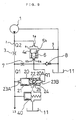
- FIG. 1 shows a conventional hydraulic power steering apparatus in which a bypass control valve is employed to reduce the energy consumption.
- a steering apparatus is disclosed in EP-A-0 594 137 published on 27.04.94 (state of the art according to Article 54(3) EPC).
- the power steering apparatus comprises a pump 1, a power cylinder 14, a reservoir 11, and a control valve 13.
- This control valve 13 is provided with variable throttles V1, V2, V3 and V4 disposed in four passages which are connected to the pump 1, a pair of chambers of the power cylinder 14 and the reservoir 11 and which form a bridge circuit.
- the power steering apparatus further comprises a flow control valve 4 and a bypass control valve 9.
- the flow control valve 4 is composed of a valve spool 4a and a spring 6 disposed in a spring chamber 6a formed at the back of the valve spool 4a.
- the flow control valve 4 is disposed in a bypass passage 5 and the flow of fluid flowing from an inlet port 5a to an outlet port 5b of the flow control valve 4 is controlled by the valve spool 4a.
- a connection port 6b of the spring chamber 6a is connected to a supply passage 2 via a control orifice 7 and to the reservoir 11 via a relief valve 8.
- the valve spool 4a responds to a pressure difference between the upstream side and downstream side of a metering orifice 3 disposed in a supply passage 2 which connects the pump 1 and the control valve 13 so that the bypass passage 5 is opened and closed by the valve spool 4a in accordance with the pressure difference, thereby maintaining the flow rate of operational fluid supplied to the control valve 13 constant.
- the connection port 6b of the spring chamber 6a is also connected to the reservoir 11 via the bypass control valve 9 which is composed of a control spool 9a having slits 9b at its rear end and a spring 10 disposed at the back of the control spool 9a.
- the slits 9b form a variable orifice which controls the flow of operational fluid flowing to the reservoir 11.
- the bypass control valve 9 is also connected to the supply passage 2 so that the back pressure of the control valve 13, i.e., load pressure is lead to the front side of the bypass control valve 9.
- the control spool 9 is moved to the left as viewed in FIG. 1 so that the variable orifice is fully opened.
- the pressure in the spring chamber 6a of the flow control valve 4 is lowered so that the valve spool 4a is displaced to open the bypass passage 5 much more. As a result, the energy consumed by the pump 1 can be reduced.
- the bypass control valve 9 has the following drawbacks.
- a very high pressure (the pressure of operational fluid at the time when discharged from the pump 1) acts on the front end surface of the control spool 9a while an atmospheric pressure (the pressure of operational fluid at the time when sucked by the pump 1) acts on the rear end surface of the control spool 9a.
- the spring 10 Due to this large pressure difference, the spring 10 must have a large spring constant in the case where it is required to control the control spool 9a within a short stroke.
- the spring constant of the spring 10 is made larger, adversary effects caused by variations in the axial position of the spring become large. This hinders accurate operation.
- selection of springs is required, thereby increasing production costs.
- An object of the present invention is to provide an improved hydraulic power steering apparatus having a bypass control valve which accurately operates and which can be manufactured at a low cost.
- Another object of the present invention is to provide an improved hydraulic power steering apparatus having a bypass control valve which uses a spring having a smaller spring constant compared to conventional bypass control valves, thereby eliminating the necessity of selection of springs.
- a hydraulic power steering comprises a pump for supplying a pressurized fluid, a power cylinder, a reservoir, a control valve, a metering orifice disposed in the middle of a supply passage connecting the pump and the control valve, a flow control valve, and a bypass control valve.
- the control valve is connected to the pump, the power cylinder and the reservoir and responds to steering operation so as to control supply of the pressurized fluid to the power cylinder.
- the flow control valve is disposed in a bypass passage connected to the supply passage at the upstream side of the metering orifice, and has a valve spool and a spring disposed in a spring chamber formed at the back of the valve spool and connected to the supply passage at the downstream side of the metering orifice via a control orifice so as to open and close the bypass passage in accordance with a pressure drop across the metering orifice.
- the bypass control valve is disposed between the spring chamber of the flow control valve and the reservoir so as to increase the amount of bypassed fluid by controlling the pressure in the spring chamber.
- the bypass control valve has a control spool, a load pressure introduction port connected to the upstream side of the control orifice for leading load pressure to a first end of the control spool, a pilot port connected to the downstream side of the control orifice for leading the pressure in the spring chamber to the second end of the control spool, and a spring disposed in a chamber formed between the control spool and the pilot port. Moreover, a pressure receiving area of the second end of the control spool is smaller than that of the first end of the control spool.
- control spool of the bypass control valve is provided with two opposite ends having different pressure receiving areas, and the control spool is controlled in accordance with differential pressure generated at the control orifice connecting the supply passage and the spring chamber of the flow control valve. Accordingly, a spring having a small spring constant can be used in the bypass control valve, even when the control spool is controlled within a short stroke. This reduces the adversary effects caused from variations in the axial mounting position of the spring, and eliminates the necessity of selection of springs so that the production costs can be lowered. In addition, the flow rate can be controlled accurately.
- FIG. 2 shows the overall structure of a hydraulic power, steering apparatus according to a first embodiment of the present invention.
- the power steering apparatus comprises a pump 1, a power cylinder 14, a control valve 13, and a reservoir 11.
- the pump 1 is driven by an unillustrated engine of an automobile.
- the control valve 13 is provided with variable throttles V1, V2, V3 and V4 disposed in four passages which are connected to the pump 1, a pair of chambers of the power cylinder 14 and the reservoir 11 and which form a bridge circuit.
- the control valve 13 is connected to the pump 1 via a supply passage 2 formed in an unillustrated pump housing and a pressure hose 12.
- a metering orifice 3 is disposed in the middle of the supply passage 2.
- the power steering apparatus further comprises a flow control valve 4 and a bypass control valve 20 of a ball poppet type.
- a bypass passage 5 is branched from the supply passage 2 on the upstream side of the metering orifice 3, and the flow control valve 4 having a valve spool 4a and a spring 6 is disposed in the bypass passage 5.
- an inlet port 5a of the flow control valve 4 is connected to the supply passage 2 on the upstream side of the metering orifice 3, while an outlet port 5b of the flow control valve 4 is connected to the reservoir 11 to complete the bypass passage 5.
- the valve spool 4a controls the flow of fluid flowing from the inlet port 5a to the outlet port 5b.
- the spring 6 is disposed in a spring chamber 6a formed at the back of the valve spool 4a so as to urge the valve spool 4a in a direction for closing the bypass passage 5.
- a connection port 6b of the spring chamber 6a is connected to the supply passage 2 via a control orifice 7 and to the reservoir 11 via a relief valve 8.
- the valve spool 4a responds to a pressure difference between the upstream side and downstream side of the metering orifice 3 disposed in the supply passage 2 so that the bypass passage 5 is opened and closed by the valve spool 4a in accordance with the pressure difference, thereby maintaining the flow rate of operational fluid supplied to the control valve 13 constant.
- connection port 6b of the spring chamber 6a is also connected to the reservoir 11 via the bypass control valve 20.
- the bypass control valve 20 is provided with a load pressure introduction port 23A at one end and a pilot port 23B at the other end.
- the load pressure introduction port 23A is connected to the upstream side of the control orifice 7, while the pilot port 23B is connected to the down stream side of the control orifice 7.
- the bypass control valve 20 comprises a control spool 21 having a first end facing the load pressure introduction port 23A, a ball 25 disposed on a second end of the control spool 21 opposite to the first end, a valve sheet member 24 disposed adjacent to the pilot port 23B and to which the ball 25 contacts, and a spring 22 disposed between the control spool 21 and the valve sheet member 24 to urge the control spool 21 in a direction such that the ball 25 is separated from the valve sheet member 24.
- the valve sheet member 24 is provided with a passage communicating with the pilot port 23B, and the ball 25 contacts an inner opening of the passage to form a pressure receiving area smaller than the first end of the control spool 21.
- a chamber formed between the control spool 21 and the valve sheet member 24 is connected to the reservoir 11 through a drain port 23D.
- the control spool 21 of the bypass control valve 20 closes the pilot port 23B so that the flow rate q of pilot flow flowing into the pilot port 23B is decreased to zero, as shown in Fig. 3.
- the pressure in the spring chamber 6b of the flow control valve 4 increases so that the valve spool 4a advances to close the bypass passage 5.
- the flow rate of the operational fluid supplied to the control valve 13 is increased as the load pressure increases.
- the load pressure reaches P2
- the flow rate reaches the maximum rate Q2, making it possible to generate a sufficient assisting force.
- bypass control valve 20 used in the first embodiment is a ball poppet type, but the bypass control valve 20 is not limited thereto and various bypass control valves according to the following embodiments may be used.
- FIG. 5 shows a bypass control valve 20 according to a second embodiment of the present invention.
- This bypass control valve 20 is a modified ball poppet type in which a projection 26 is projected from the second end surface of the control spool 21, and the projection 26 has a flat end surface which is capable of contracting the inner opening of a passage communicating with the pilot port 23B.
- the bypass control valve 20 of the present embodiment operates in the same manner as the bypass control valve 20 according to the first embodiment.
- FIG. 6 shows a bypass control valve 20 according to a third embodiment of the present invention.
- a stepped hole is formed for receiving the control spool 21.
- the hole has a larger diameter portion formed over an area adjacent to the load pressure introduction port 23A and a smaller diameter portion formed over an area adjacent the pilot port 23B.
- the larger diameter portion has a diameter E1 which is larger than the diameter E2 of the smaller diameter portion.
- the control spool 21 also has a larger diameter portion and a smaller diameter portion having diameters slightly smaller than the diameters E1 and E2, respectively.
- a variable throttle 20A is formed between a stepped portion of the control spool 21 formed between its larger and smaller diameter portions and an inlet passage 23C which is connected to the spring chamber 6a of the flow control valve 4.
- the control spool 21 is axially moved in accordance with a differential pressure produced at the control orifice 7 so that the variable orifice 20A is opened and closed.
- FIG. 7 shows a bypass control valve 20 according to a fourth embodiment of the present invention.
- a first rod 28 is provided at its one axial end, and a second rod 29 having a cross section smaller than that of the first rod 28 is formed at the other axial end.
- the first rod 28 is received by a hole formed in a first end of a control spool 21 to form a first pressure receiving chamber 30, while the second rod 29 is received by a hole formed in a second end of the control spool 21 to form a second pressure receiving chamber 31.
- the bypass control valve 20 is provided with a load pressure introduction port 23A which is connected to the upstream side of the control orifice 7 and a pilot port 23B which is connected to the downstream side of the control orifice 7.
- a first connection hole 32 is formed to introduce load pressure from the load pressure introduction port 23A to the first pressure receiving chamber 30.
- a second connection hole 33 is formed to introduce pilot pressure from the pilot port 23B to the second pressure receiving chamber 31.
- a variable throttle 20A is formed between a stepped portion of the control spool 21 and an inlet passage 23C which is connected to the spring chamber 6a of the flow control valve 4.
- the control spool 21 is axially moved in accordance with a differential pressure produced at the control orifice 7 so that the variable throttle 20A is opened and closed.
- FIG. 8 shows a bypass control valve 20 according to a fifth embodiment of the present invention.
- a main spool 21A and a sub spool 21B having a sectional area smaller than that of the main spool 21A are used.
- the main spool 21A is received in a first hole having a load pressure introduction port 23A, an inlet port 23C, and a drain port 23D.
- the main spool 21A is urged by a spring 22 to move toward the load pressure introduction port 23A so that a variable throttle 20A formed between a stepped portion of the main spool 21A and the inlet port 23C is opened.
- the sub spool 21B is received in a second hole having a pilot port 23B, and is provided with a projection contacting the main spool 21A.
- the main spool 21A and the sub spool 21B are axially moved together in accordance with a differential pressure produced at the control orifice 7 so that the variable orifice 20A is opened and closed.
- FIG. 9 shows a sixth embodiment of the present invention.
- This embodiment is the same as the first embodiment except that an additional control valve is added to improve the safety.
- a safety valve 40 comprising a spool and a spring is disposed between the bypass control valve 20 and the reservoir 11.
- the safety valve 40 is also connected to the supply passage 2 so that load pressure acts on the spool of the safety valve 40.
- the bypass control valve 20 is left opened due to a malfunction even though the load pressure increases, the safety valve 40 is closed when the load pressure reaches a predetermined level P2.
- the flow control valve 4 normally operates to supply operational fluid at a flow rate Q2.
- the flow rate of operational fluid is maintained constant by the flow control valve 4.
- a variable throttle whose opening area varies in accordance with vehicle speed or the rotational speed of an engine may be used as the metering orifice to change the flow rate according to the vehicle speed or the rotational speed of the engine.
Landscapes
- Engineering & Computer Science (AREA)
- Chemical & Material Sciences (AREA)
- Combustion & Propulsion (AREA)
- Transportation (AREA)
- Mechanical Engineering (AREA)
- Power Steering Mechanism (AREA)
Description
- The present invention relates to a hydraulic power steering apparatus suitable for use in automobiles and the like.
- FIG. 1 shows a conventional hydraulic power steering apparatus in which a bypass control valve is employed to reduce the energy consumption. Such a steering apparatus is disclosed in EP-A-0 594 137 published on 27.04.94 (state of the art according to Article 54(3) EPC). The power steering apparatus comprises a
pump 1, apower cylinder 14, areservoir 11, and acontrol valve 13. Thiscontrol valve 13 is provided with variable throttles V1, V2, V3 and V4 disposed in four passages which are connected to thepump 1, a pair of chambers of thepower cylinder 14 and thereservoir 11 and which form a bridge circuit. The power steering apparatus further comprises aflow control valve 4 and abypass control valve 9. - The
flow control valve 4 is composed of a valve spool 4a and aspring 6 disposed in aspring chamber 6a formed at the back of the valve spool 4a. Theflow control valve 4 is disposed in abypass passage 5 and the flow of fluid flowing from aninlet port 5a to anoutlet port 5b of theflow control valve 4 is controlled by the valve spool 4a. Aconnection port 6b of thespring chamber 6a is connected to asupply passage 2 via acontrol orifice 7 and to thereservoir 11 via arelief valve 8. The valve spool 4a responds to a pressure difference between the upstream side and downstream side of ametering orifice 3 disposed in asupply passage 2 which connects thepump 1 and thecontrol valve 13 so that thebypass passage 5 is opened and closed by the valve spool 4a in accordance with the pressure difference, thereby maintaining the flow rate of operational fluid supplied to thecontrol valve 13 constant. Theconnection port 6b of thespring chamber 6a is also connected to thereservoir 11 via thebypass control valve 9 which is composed of acontrol spool 9a having slits 9b at its rear end and aspring 10 disposed at the back of thecontrol spool 9a. Theslits 9b form a variable orifice which controls the flow of operational fluid flowing to thereservoir 11. Thebypass control valve 9 is also connected to thesupply passage 2 so that the back pressure of thecontrol valve 13, i.e., load pressure is lead to the front side of thebypass control valve 9. When the back pressure of thecontrol valve 13 is low, i.e., thecontrol valve 13 is in a neutral state, thecontrol spool 9 is moved to the left as viewed in FIG. 1 so that the variable orifice is fully opened. With this operation, the pressure in thespring chamber 6a of theflow control valve 4 is lowered so that the valve spool 4a is displaced to open thebypass passage 5 much more. As a result, the energy consumed by thepump 1 can be reduced. - The
bypass control valve 9, however, has the following drawbacks. When thecontrol valve 13 is operated, a very high pressure (the pressure of operational fluid at the time when discharged from the pump 1) acts on the front end surface of thecontrol spool 9a while an atmospheric pressure (the pressure of operational fluid at the time when sucked by the pump 1) acts on the rear end surface of thecontrol spool 9a. Due to this large pressure difference, thespring 10 must have a large spring constant in the case where it is required to control thecontrol spool 9a within a short stroke. When the spring constant of thespring 10 is made larger, adversary effects caused by variations in the axial position of the spring become large. This hinders accurate operation. Moreover, in order to secure that each spring has the same spring constant, selection of springs is required, thereby increasing production costs. - An object of the present invention is to provide an improved hydraulic power steering apparatus having a bypass control valve which accurately operates and which can be manufactured at a low cost.
- Another object of the present invention is to provide an improved hydraulic power steering apparatus having a bypass control valve which uses a spring having a smaller spring constant compared to conventional bypass control valves, thereby eliminating the necessity of selection of springs.
- Briefly, a hydraulic power steering according to the present invention comprises a pump for supplying a pressurized fluid, a power cylinder, a reservoir, a control valve, a metering orifice disposed in the middle of a supply passage connecting the pump and the control valve, a flow control valve, and a bypass control valve. The control valve is connected to the pump, the power cylinder and the reservoir and responds to steering operation so as to control supply of the pressurized fluid to the power cylinder.
- The flow control valve is disposed in a bypass passage connected to the supply passage at the upstream side of the metering orifice, and has a valve spool and a spring disposed in a spring chamber formed at the back of the valve spool and connected to the supply passage at the downstream side of the metering orifice via a control orifice so as to open and close the bypass passage in accordance with a pressure drop across the metering orifice. The bypass control valve is disposed between the spring chamber of the flow control valve and the reservoir so as to increase the amount of bypassed fluid by controlling the pressure in the spring chamber. The bypass control valve has a control spool, a load pressure introduction port connected to the upstream side of the control orifice for leading load pressure to a first end of the control spool, a pilot port connected to the downstream side of the control orifice for leading the pressure in the spring chamber to the second end of the control spool, and a spring disposed in a chamber formed between the control spool and the pilot port. Moreover, a pressure receiving area of the second end of the control spool is smaller than that of the first end of the control spool.
- In the present invention, the control spool of the bypass control valve is provided with two opposite ends having different pressure receiving areas, and the control spool is controlled in accordance with differential pressure generated at the control orifice connecting the supply passage and the spring chamber of the flow control valve. Accordingly, a spring having a small spring constant can be used in the bypass control valve, even when the control spool is controlled within a short stroke. This reduces the adversary effects caused from variations in the axial mounting position of the spring, and eliminates the necessity of selection of springs so that the production costs can be lowered. In addition, the flow rate can be controlled accurately.
- Various other objects, features and many of the attendant advantages of the present invention will be readily appreciated as the same becomes better understood by reference to the following detailed description of the preferred embodiments when considered in connection with the accompanying drawings, in which:
- FIG. 1 is a diagram showing the overall structure of a conventional hydraulic power steering apparatus;
- FIG. 2 is a diagram showing the overall structure of a power steering apparatus according to a first embodiment of the present invention;
- FIG. 3 is a graph showing the relationship between load pressure and pilot flow rate;
- FIG. 4 is a graph showing the relationship between load pressure and the flow rate of fluid supplied to the control valve;
- FIG. 5 is a sectional view of a bypass control valve according to a second embodiment of the present invention;
- FIG. 6 is a sectional view of a bypass control valve according to a third embodiment of the present invention;
- FIG. 7 is a sectional view of a bypass control valve according to a fourth embodiment of the present invention;
- FIG. 8 is a sectional view of a bypass control valve according to a fifth embodiment of the present invention; and
- FIG. 9 is a diagram showing a main portion of a power steering apparatus according to a sixth embodiment of the present invention.
- Embodiments of the present invention will now be described with reference to the accompanying drawings.
- FIG. 2 shows the overall structure of a hydraulic power, steering apparatus according to a first embodiment of the present invention. The power steering apparatus comprises a
pump 1, apower cylinder 14, acontrol valve 13, and areservoir 11. Thepump 1 is driven by an unillustrated engine of an automobile. Thecontrol valve 13 is provided with variable throttles V1, V2, V3 and V4 disposed in four passages which are connected to thepump 1, a pair of chambers of thepower cylinder 14 and thereservoir 11 and which form a bridge circuit. - The
control valve 13 is connected to thepump 1 via asupply passage 2 formed in an unillustrated pump housing and apressure hose 12. Ametering orifice 3 is disposed in the middle of thesupply passage 2. - The power steering apparatus further comprises a
flow control valve 4 and abypass control valve 20 of a ball poppet type. - A
bypass passage 5 is branched from thesupply passage 2 on the upstream side of themetering orifice 3, and theflow control valve 4 having a valve spool 4a and aspring 6 is disposed in thebypass passage 5. In detail, aninlet port 5a of theflow control valve 4 is connected to thesupply passage 2 on the upstream side of themetering orifice 3, while anoutlet port 5b of theflow control valve 4 is connected to thereservoir 11 to complete thebypass passage 5. The valve spool 4a controls the flow of fluid flowing from theinlet port 5a to theoutlet port 5b. Thespring 6 is disposed in aspring chamber 6a formed at the back of the valve spool 4a so as to urge the valve spool 4a in a direction for closing thebypass passage 5. Aconnection port 6b of thespring chamber 6a is connected to thesupply passage 2 via acontrol orifice 7 and to thereservoir 11 via arelief valve 8. The valve spool 4a responds to a pressure difference between the upstream side and downstream side of themetering orifice 3 disposed in thesupply passage 2 so that thebypass passage 5 is opened and closed by the valve spool 4a in accordance with the pressure difference, thereby maintaining the flow rate of operational fluid supplied to thecontrol valve 13 constant. - The
connection port 6b of thespring chamber 6a is also connected to thereservoir 11 via thebypass control valve 20. Thebypass control valve 20 is provided with a loadpressure introduction port 23A at one end and apilot port 23B at the other end. The loadpressure introduction port 23A is connected to the upstream side of thecontrol orifice 7, while thepilot port 23B is connected to the down stream side of thecontrol orifice 7. Thebypass control valve 20 comprises acontrol spool 21 having a first end facing the loadpressure introduction port 23A, aball 25 disposed on a second end of thecontrol spool 21 opposite to the first end, avalve sheet member 24 disposed adjacent to thepilot port 23B and to which theball 25 contacts, and aspring 22 disposed between thecontrol spool 21 and thevalve sheet member 24 to urge thecontrol spool 21 in a direction such that theball 25 is separated from thevalve sheet member 24. Thevalve sheet member 24 is provided with a passage communicating with thepilot port 23B, and theball 25 contacts an inner opening of the passage to form a pressure receiving area smaller than the first end of thecontrol spool 21. A chamber formed between thecontrol spool 21 and thevalve sheet member 24 is connected to thereservoir 11 through adrain port 23D. - When the
control valve 13 is in its neutral state, the load pressure is at a low level P1 so that only a small differential pressure is produced across thecontrol orifice 7. In such a case, avariable throttle 20A of thebypass control valve 20 is fully opened due to the spring force of thespring 22. As a result, thespring chamber 6a of theflow control valve 4 communicates with thereservoir 11 so that the pressure in thespring chamber 6a is lowered. This causes the valve spool 4a to retract so as to open thebypass passage 5. Accordingly, the operational fluid discharged from thepump 1 is mostly bypassed to thereservoir 11. With this operation, the flow rate of the operational fluid supplied to thecontrol valve 13 is reduced to the lowest flow rate Q1, as shown in FIG. 4. - When an unillustrated steering wheel is rotated, the opening areas of one pair of variable orifices V1 and V4 are increased, while the opening areas of the other pair of variable orifices V2 and V3 are decreased. As a result, the back pressure of the
control valve 13, i.e., load pressure gradually increases. When the load pressure increases, the differential pressure produced across thecontrol orifice 7 increases. When the differential pressure reaches a predetermined level, thecontrol spool 21 is moved toward thepilot port 23B against the spring force of thespring 22, thereby decreasing the opening area of thevariable throttle 20A. When the differential pressure produced at thecontrol orifice 7 is further increased due to a further increase of the load pressure, thecontrol spool 21 of thebypass control valve 20 closes thepilot port 23B so that the flow rate q of pilot flow flowing into thepilot port 23B is decreased to zero, as shown in Fig. 3. With this operation, the pressure in thespring chamber 6b of theflow control valve 4 increases so that the valve spool 4a advances to close thebypass passage 5. As a result, the flow rate of the operational fluid supplied to thecontrol valve 13 is increased as the load pressure increases. When the load pressure reaches P2, the flow rate reaches the maximum rate Q2, making it possible to generate a sufficient assisting force. - The
bypass control valve 20 used in the first embodiment is a ball poppet type, but thebypass control valve 20 is not limited thereto and various bypass control valves according to the following embodiments may be used. - FIG. 5 shows a
bypass control valve 20 according to a second embodiment of the present invention. Thisbypass control valve 20 is a modified ball poppet type in which a projection 26 is projected from the second end surface of thecontrol spool 21, and the projection 26 has a flat end surface which is capable of contracting the inner opening of a passage communicating with thepilot port 23B. Thebypass control valve 20 of the present embodiment operates in the same manner as thebypass control valve 20 according to the first embodiment. - FIG. 6 shows a
bypass control valve 20 according to a third embodiment of the present invention. In thisbypass control valve 20, a stepped hole is formed for receiving thecontrol spool 21. In detail, the hole has a larger diameter portion formed over an area adjacent to the loadpressure introduction port 23A and a smaller diameter portion formed over an area adjacent thepilot port 23B. The larger diameter portion has a diameter E1 which is larger than the diameter E2 of the smaller diameter portion. Thecontrol spool 21 also has a larger diameter portion and a smaller diameter portion having diameters slightly smaller than the diameters E1 and E2, respectively. Avariable throttle 20A is formed between a stepped portion of thecontrol spool 21 formed between its larger and smaller diameter portions and aninlet passage 23C which is connected to thespring chamber 6a of theflow control valve 4. In thebypass control valve 20 of the present invention, thecontrol spool 21 is axially moved in accordance with a differential pressure produced at thecontrol orifice 7 so that thevariable orifice 20A is opened and closed. - FIG. 7 shows a
bypass control valve 20 according to a fourth embodiment of the present invention. In thisbypass control valve 20, afirst rod 28 is provided at its one axial end, and asecond rod 29 having a cross section smaller than that of thefirst rod 28 is formed at the other axial end. Thefirst rod 28 is received by a hole formed in a first end of acontrol spool 21 to form a firstpressure receiving chamber 30, while thesecond rod 29 is received by a hole formed in a second end of thecontrol spool 21 to form a secondpressure receiving chamber 31. Thebypass control valve 20 is provided with a loadpressure introduction port 23A which is connected to the upstream side of thecontrol orifice 7 and apilot port 23B which is connected to the downstream side of thecontrol orifice 7. In thecontrol spool 21, afirst connection hole 32 is formed to introduce load pressure from the loadpressure introduction port 23A to the firstpressure receiving chamber 30. Also, asecond connection hole 33 is formed to introduce pilot pressure from thepilot port 23B to the secondpressure receiving chamber 31. Avariable throttle 20A is formed between a stepped portion of thecontrol spool 21 and aninlet passage 23C which is connected to thespring chamber 6a of theflow control valve 4. In thebypass control valve 20 of the present invention, thecontrol spool 21 is axially moved in accordance with a differential pressure produced at thecontrol orifice 7 so that thevariable throttle 20A is opened and closed. - FIG. 8 shows a
bypass control valve 20 according to a fifth embodiment of the present invention. In thisbypass control valve 20, amain spool 21A and asub spool 21B having a sectional area smaller than that of themain spool 21A are used. Themain spool 21A is received in a first hole having a loadpressure introduction port 23A, aninlet port 23C, and adrain port 23D. Themain spool 21A is urged by aspring 22 to move toward the loadpressure introduction port 23A so that avariable throttle 20A formed between a stepped portion of themain spool 21A and theinlet port 23C is opened. Thesub spool 21B is received in a second hole having apilot port 23B, and is provided with a projection contacting themain spool 21A. In thebypass control valve 20 of the present invention, themain spool 21A and thesub spool 21B are axially moved together in accordance with a differential pressure produced at thecontrol orifice 7 so that thevariable orifice 20A is opened and closed. - FIG. 9 shows a sixth embodiment of the present invention. This embodiment is the same as the first embodiment except that an additional control valve is added to improve the safety. In detail, a safety valve 40 comprising a spool and a spring is disposed between the
bypass control valve 20 and thereservoir 11. The safety valve 40 is also connected to thesupply passage 2 so that load pressure acts on the spool of the safety valve 40. In the case where thebypass control valve 20 is left opened due to a malfunction even though the load pressure increases, the safety valve 40 is closed when the load pressure reaches a predetermined level P2. As a result, theflow control valve 4 normally operates to supply operational fluid at a flow rate Q2. - In the above embodiments, the flow rate of operational fluid is maintained constant by the
flow control valve 4. However, a variable throttle whose opening area varies in accordance with vehicle speed or the rotational speed of an engine may be used as the metering orifice to change the flow rate according to the vehicle speed or the rotational speed of the engine. - Obviously, numerous modifications and variations of the present invention are possible in light of the above teachings. It is therefore to be understood that within the scope of the appended claims, the present invention may be practiced otherwise than as specifically described herein.
Claims (7)
- A hydraulic power steering apparatus having a pump (1) for supplying an operational fluid, a power cylinder (14), a reservoir (11), and a control valve (13) connected to said pump, said power cylinder and said reservoir and responsive to steering operation for controlling supply of the operational fluid to said power cylinder (14), said power steering apparatus comprising;a metering orifice (3) disposed in the middle of a supply passage (2) connecting said pump (1) and said control valve (13);a flow control valve (4) which is disposed in a bypass passage (5) connected to the supply passage (2) at the upstream side of said metering orifice (3) and which comprises a valve spool (4a) and a spring (6) disposed in a spring chamber (6a) formed at the back of the valve spool and connected to the supply passage (2) at the downstream side of said metering orifice (3) via a control orifice (7) so as to open and close the bypass passage in accordance with a pressure drop across said metering orifice (3); anda bypass control valve (20) disposed between the spring chamber (6a) of said flow control valve (4) and said reservoir (11) so as to increase the amount of bypassed fluid by controlling the pressure in the spring chamber,
wherein said bypass control valve (20) has a control spool (21), a load pressure introduction port (23A) connected to the upstream side of the control orifice (7) for leading load pressure to a first end of said control spool (21), a pilot port (23B) connected to the downstream side of the control orifice (7) for leading the pressure in the spring chamber (6a) of said flow control valve to a second end of said control spool (21), and a spring (22) disposed in a chamber formed between said control spool (21) and said pilot port (23B), and wherein a pressure receiving area of the second end of the control spool (21) is smaller than that of the first end of the control spool. - A hydraulic power steering apparatus according to claim 1, wherein said control spool (21) of said bypass control valve (20) is provided with a ball (25) which is disposed at the second end of said control spool and contacts an inner opening of a passage communicating with said pilot port (23B) to form a pressure receiving area smaller than the first end of said control spool (21), and a drain port (23D) is formed to drain operational fluid from the chamber to said reservoir.
- A hydraulic power steering apparatus according to claim 1, wherein said control spool (21) of said bypass control valve (20) is provided with a projection (26) projected from the second end of said control spool (21) and having a flat end which contacts an inner opening of a passage communicating with said pilot port (23B) to form a pressure receiving area smaller than the first end of said control spool, and a drain port (23D) is formed to drain operational fluid from the chamber to said reservoir.
- A hydraulic power steering apparatus according to claim 1, wherein said control spool (21) of said bypass control valve has a larger diameter portion providing said first end and a smaller diameter portion providing said second end, said bypass control valve (20) is provided with an inlet port (23C) connected to the spring chamber (6a) of said flow control valve (4), and a drain port (23D) which is connected to said reservoir (11), and a variable throttle (20A) is formed between a stepped portion between the large diameter portion and the small diameter portion of the control spool (21) and said inlet port (23C) for controlling the flow of operational fluid from the inlet port to the drain port.
- A hydraulic power steering apparatus according to claim 1, wherein said bypass control valve (20) is provided with a first rod (28) and a second rod (29) having a cross section smaller than that of the first rod which are received by holes formed in the first and second ends of the control spool (21) to form first and second pressure receiving chambers (30, 31), the control spool has a first connection hole (32) for connecting the load pressure introduction port (23A) and the first pressure receiving chamber (30) and a second connection hole (33) for connecting the pilot port (23B) and the second pressure receiving chamber (31), said bypass control valve is further provided with an inlet port (23C) connected to the spring chamber (6a) of said flow control valve (4) and a drain port (23D) which is connected to said reservoir, and a variable throttle (20A) is formed between a stepped portion formed on the control spool (21) and said inlet port (23C) for controlling the flow of operational fluid from the inlet port to the drain port.
- A hydraulic power steering apparatus according to claim 1, wherein said control spool of said bypass control valve (20) is composed of a main spool (21A) received in a first hole and a sub spool (21B) received in a second hole and having a rod contacting the main spool (21A), said first hole is provided with said load pressure introduction port (23A) for applying load pressure to the main spool, an inlet port (23C) connected to the spring chamber (6a) of said flow control valve (4) and a drain port (23D) connected to said reservoir (11), a variable throttle (20A) is formed between a stepped portion formed on the control spool and said inlet port (23C) for controlling the flow of operational fluid from the inlet port to the drain port, and said second hole is provided with said pilot port (23B) for applying the pressure in the spring chamber of said flow control valve to the sub spool (21B).
- A hydraulic power steering apparatus according to claim 1, further comprising a safety valve (40) which is disposed between said bypass control valve (20) and said reservoir (11) and operates to stop the flow of fluid from said bypass control valve to said reservoir when the back pressure of said control valve (13) reaches a predetermined level.
Applications Claiming Priority (2)
| Application Number | Priority Date | Filing Date | Title |
|---|---|---|---|
| JP24974193A JP3188067B2 (en) | 1993-09-13 | 1993-09-13 | Power steering device |
| JP249741/93 | 1993-09-13 |
Publications (2)
| Publication Number | Publication Date |
|---|---|
| EP0642970A1 EP0642970A1 (en) | 1995-03-15 |
| EP0642970B1 true EP0642970B1 (en) | 1997-11-12 |
Family
ID=17197527
Family Applications (1)
| Application Number | Title | Priority Date | Filing Date |
|---|---|---|---|
| EP94114287A Expired - Lifetime EP0642970B1 (en) | 1993-09-13 | 1994-09-12 | Hydraulic power steering apparatus |
Country Status (4)
| Country | Link |
|---|---|
| US (1) | US5474145A (en) |
| EP (1) | EP0642970B1 (en) |
| JP (1) | JP3188067B2 (en) |
| DE (1) | DE69406742T2 (en) |
Families Citing this family (9)
| Publication number | Priority date | Publication date | Assignee | Title |
|---|---|---|---|---|
| EP0658468B1 (en) * | 1993-12-16 | 1999-04-14 | Toyoda Koki Kabushiki Kaisha | Hydraulic power steering apparatus |
| DE4418118C1 (en) * | 1994-05-24 | 1995-07-06 | Daimler Benz Ag | Servo steering control for automobile |
| JP3365447B2 (en) * | 1994-05-31 | 2003-01-14 | 豊田工機株式会社 | Power steering device |
| JPH09249136A (en) * | 1996-03-14 | 1997-09-22 | Unisia Jecs Corp | Flow control device |
| JP3463453B2 (en) * | 1996-03-28 | 2003-11-05 | 豊田工機株式会社 | Power steering device |
| JPH11217081A (en) * | 1997-11-27 | 1999-08-10 | Kayaba Ind Co Ltd | Power steering system |
| US6561297B2 (en) * | 2000-09-06 | 2003-05-13 | Suzuki Motor Corporation | Snowmobile four-cycle engine arrangement |
| DE60323993D1 (en) * | 2002-09-09 | 2008-11-20 | Nok Corp | POLYMER EMBRANE (M-PHENYLENISOPHTHAL-AMID) |
| US7420851B2 (en) * | 2006-10-24 | 2008-09-02 | San Disk 3D Llc | Memory device for controlling current during programming of memory cells |
Family Cites Families (6)
| Publication number | Priority date | Publication date | Assignee | Title |
|---|---|---|---|---|
| DE2126085A1 (en) * | 1971-05-26 | 1972-12-07 | Daimler Benz Ag, 7000 Stuttgart | Vehicle auxiliary internal combustion engine |
| US4332303A (en) * | 1980-08-04 | 1982-06-01 | Zahnradfabrik Friedrichshafen, Ag | Auxiliary power steering |
| US5184691A (en) * | 1988-08-26 | 1993-02-09 | Zahnradfabrik Friedrichshafen, Ag. | Auxiliary power steering system |
| WO1990003908A2 (en) * | 1988-10-04 | 1990-04-19 | Alfred Teves Gmbh | Hydraulic servo-assisted steering system for motor vehicles |
| DE69324954T2 (en) * | 1992-03-27 | 2000-02-24 | Toyoda Koki K.K., Kariya | Power steering |
| US5439070A (en) * | 1992-06-12 | 1995-08-08 | Toyoda Koki Kabushiki Kaisha | Hydraulic power steering apparatus |
-
1993
- 1993-09-13 JP JP24974193A patent/JP3188067B2/en not_active Expired - Fee Related
-
1994
- 1994-09-12 DE DE69406742T patent/DE69406742T2/en not_active Expired - Lifetime
- 1994-09-12 EP EP94114287A patent/EP0642970B1/en not_active Expired - Lifetime
- 1994-09-13 US US08/304,923 patent/US5474145A/en not_active Expired - Lifetime
Also Published As
| Publication number | Publication date |
|---|---|
| DE69406742D1 (en) | 1997-12-18 |
| US5474145A (en) | 1995-12-12 |
| JPH0781593A (en) | 1995-03-28 |
| JP3188067B2 (en) | 2001-07-16 |
| DE69406742T2 (en) | 1998-03-26 |
| EP0642970A1 (en) | 1995-03-15 |
Similar Documents
| Publication | Publication Date | Title |
|---|---|---|
| US4420934A (en) | Automotive vehicle hydraulic system | |
| US4400938A (en) | Hydraulic fluid feeding device for power steering device | |
| US4798256A (en) | Hydrostatic auxiliary steering device | |
| US5439070A (en) | Hydraulic power steering apparatus | |
| US5785075A (en) | Fluid-flow control valve | |
| US6041883A (en) | Flow controlling apparatus for power steering systems | |
| EP0658468B1 (en) | Hydraulic power steering apparatus | |
| GB2277306A (en) | Vehicle power steering apparatus with reduced output at high pump speeds | |
| US4768605A (en) | Apparatus for use in a power steering system | |
| EP0186135B1 (en) | Hydraulic reaction force apparatus for power steering system | |
| US4396033A (en) | Flow volume control device for a power assisted steering device | |
| US5474145A (en) | Hydraulic power steering apparatus | |
| US6959639B2 (en) | Hydraulic booster brake system | |
| US5822988A (en) | Flow control device of a power steering apparatus | |
| JPH0911922A (en) | Power steering device | |
| US5170626A (en) | Hydraulic flow control system for automotive vehicle | |
| US5651423A (en) | Power steering apparatus | |
| JP3237457B2 (en) | Flow control device in power steering device | |
| JP3793662B2 (en) | Flow control valve for power steering device | |
| US20240359731A1 (en) | Hydraulic steering system | |
| EP0678672B1 (en) | Flow control mechanism for power steering | |
| JPH0137974Y2 (en) | ||
| JP3484503B2 (en) | Power steering device | |
| JPH0246459Y2 (en) | ||
| JPH07267117A (en) | Flow control device of power steering device |
Legal Events
| Date | Code | Title | Description |
|---|---|---|---|
| PUAI | Public reference made under article 153(3) epc to a published international application that has entered the european phase |
Free format text: ORIGINAL CODE: 0009012 |
|
| AK | Designated contracting states |
Kind code of ref document: A1 Designated state(s): DE FR GB |
|
| 17P | Request for examination filed |
Effective date: 19950517 |
|
| GRAG | Despatch of communication of intention to grant |
Free format text: ORIGINAL CODE: EPIDOS AGRA |
|
| 17Q | First examination report despatched |
Effective date: 19961216 |
|
| GRAH | Despatch of communication of intention to grant a patent |
Free format text: ORIGINAL CODE: EPIDOS IGRA |
|
| GRAH | Despatch of communication of intention to grant a patent |
Free format text: ORIGINAL CODE: EPIDOS IGRA |
|
| GRAA | (expected) grant |
Free format text: ORIGINAL CODE: 0009210 |
|
| AK | Designated contracting states |
Kind code of ref document: B1 Designated state(s): DE FR GB |
|
| REF | Corresponds to: |
Ref document number: 69406742 Country of ref document: DE Date of ref document: 19971218 |
|
| ET | Fr: translation filed | ||
| PLBE | No opposition filed within time limit |
Free format text: ORIGINAL CODE: 0009261 |
|
| STAA | Information on the status of an ep patent application or granted ep patent |
Free format text: STATUS: NO OPPOSITION FILED WITHIN TIME LIMIT |
|
| 26N | No opposition filed | ||
| REG | Reference to a national code |
Ref country code: GB Ref legal event code: IF02 |
|
| REG | Reference to a national code |
Ref country code: GB Ref legal event code: 746 Effective date: 20111114 |
|
| REG | Reference to a national code |
Ref country code: DE Ref legal event code: R084 Ref document number: 69406742 Country of ref document: DE Effective date: 20111108 |
|
| PGFP | Annual fee paid to national office [announced via postgrant information from national office to epo] |
Ref country code: DE Payment date: 20130904 Year of fee payment: 20 |
|
| PGFP | Annual fee paid to national office [announced via postgrant information from national office to epo] |
Ref country code: GB Payment date: 20130911 Year of fee payment: 20 Ref country code: FR Payment date: 20130910 Year of fee payment: 20 |
|
| REG | Reference to a national code |
Ref country code: DE Ref legal event code: R071 Ref document number: 69406742 Country of ref document: DE |
|
| REG | Reference to a national code |
Ref country code: DE Ref legal event code: R071 Ref document number: 69406742 Country of ref document: DE |
|
| REG | Reference to a national code |
Ref country code: GB Ref legal event code: PE20 Expiry date: 20140911 |
|
| PG25 | Lapsed in a contracting state [announced via postgrant information from national office to epo] |
Ref country code: DE Free format text: LAPSE BECAUSE OF EXPIRATION OF PROTECTION Effective date: 20140913 |
|
| PG25 | Lapsed in a contracting state [announced via postgrant information from national office to epo] |
Ref country code: GB Free format text: LAPSE BECAUSE OF EXPIRATION OF PROTECTION Effective date: 20140911 |