EP0642151A2 - Night vision scope with voltage supply - Google Patents
Night vision scope with voltage supply Download PDFInfo
- Publication number
- EP0642151A2 EP0642151A2 EP94116461A EP94116461A EP0642151A2 EP 0642151 A2 EP0642151 A2 EP 0642151A2 EP 94116461 A EP94116461 A EP 94116461A EP 94116461 A EP94116461 A EP 94116461A EP 0642151 A2 EP0642151 A2 EP 0642151A2
- Authority
- EP
- European Patent Office
- Prior art keywords
- voltage
- image
- night vision
- voltage supply
- infrared
- Prior art date
- Legal status (The legal status is an assumption and is not a legal conclusion. Google has not performed a legal analysis and makes no representation as to the accuracy of the status listed.)
- Granted
Links
- 230000004297 night vision Effects 0.000 title claims abstract description 41
- 238000005286 illumination Methods 0.000 claims abstract description 6
- 238000007789 sealing Methods 0.000 claims 1
- OAICVXFJPJFONN-UHFFFAOYSA-N Phosphorus Chemical compound [P] OAICVXFJPJFONN-UHFFFAOYSA-N 0.000 description 6
- 238000010586 diagram Methods 0.000 description 5
- 239000013307 optical fiber Substances 0.000 description 4
- 238000000034 method Methods 0.000 description 3
- WHXSMMKQMYFTQS-UHFFFAOYSA-N Lithium Chemical compound [Li] WHXSMMKQMYFTQS-UHFFFAOYSA-N 0.000 description 2
- 238000006243 chemical reaction Methods 0.000 description 2
- 238000010276 construction Methods 0.000 description 2
- 230000007613 environmental effect Effects 0.000 description 2
- 210000000887 face Anatomy 0.000 description 2
- 239000000835 fiber Substances 0.000 description 2
- 238000002329 infrared spectrum Methods 0.000 description 2
- 229910052744 lithium Inorganic materials 0.000 description 2
- 235000012431 wafers Nutrition 0.000 description 2
- 239000003990 capacitor Substances 0.000 description 1
- 238000005253 cladding Methods 0.000 description 1
- 230000001351 cycling effect Effects 0.000 description 1
- 230000000694 effects Effects 0.000 description 1
- 238000005516 engineering process Methods 0.000 description 1
- 238000004519 manufacturing process Methods 0.000 description 1
- 238000012986 modification Methods 0.000 description 1
- 230000004048 modification Effects 0.000 description 1
- 230000005855 radiation Effects 0.000 description 1
- 230000035939 shock Effects 0.000 description 1
- 238000001429 visible spectrum Methods 0.000 description 1
- XLYOFNOQVPJJNP-UHFFFAOYSA-N water Substances O XLYOFNOQVPJJNP-UHFFFAOYSA-N 0.000 description 1
Images


Classifications
-
- H—ELECTRICITY
- H01—ELECTRIC ELEMENTS
- H01J—ELECTRIC DISCHARGE TUBES OR DISCHARGE LAMPS
- H01J29/00—Details of cathode-ray tubes or of electron-beam tubes of the types covered by group H01J31/00
- H01J29/98—Circuit arrangements not adapted to a particular application of the tube and not otherwise provided for
-
- G—PHYSICS
- G02—OPTICS
- G02B—OPTICAL ELEMENTS, SYSTEMS OR APPARATUS
- G02B23/00—Telescopes, e.g. binoculars; Periscopes; Instruments for viewing the inside of hollow bodies; Viewfinders; Optical aiming or sighting devices
- G02B23/12—Telescopes, e.g. binoculars; Periscopes; Instruments for viewing the inside of hollow bodies; Viewfinders; Optical aiming or sighting devices with means for image conversion or intensification
-
- H—ELECTRICITY
- H01—ELECTRIC ELEMENTS
- H01J—ELECTRIC DISCHARGE TUBES OR DISCHARGE LAMPS
- H01J31/00—Cathode ray tubes; Electron beam tubes
- H01J31/08—Cathode ray tubes; Electron beam tubes having a screen on or from which an image or pattern is formed, picked up, converted, or stored
- H01J31/50—Image-conversion or image-amplification tubes, i.e. having optical, X-ray, or analogous input, and optical output
- H01J31/506—Image-conversion or image-amplification tubes, i.e. having optical, X-ray, or analogous input, and optical output tubes using secondary emission effect
- H01J31/507—Image-conversion or image-amplification tubes, i.e. having optical, X-ray, or analogous input, and optical output tubes using secondary emission effect using a large number of channels, e.g. microchannel plates
Definitions
- the invention relates to night vision scopes.
- Night vision scopes are used generally by military and law enforcement personnel for operations in low light conditions. This enables military and law enforcement personnel to use the night vision scopes to observe conditions at night and in dark buildings. A night vision scope allows the user to continue to make tactical advances and observe hostile tactical advances. New night vision scopes are also designed to assist pilots of helicopters and planes to more easily fly at night.
- night vision scopes utilize image intensification technologies. That is, the night vision scope receives ambient light from the environment and intensifies the image to produce an output image which is visible to the human eye.
- the present generation of night vision scopes operate to intensify low levels of visible light and make visible the light from the infrared spectrum.
- the image intensification process involves conversion of the received ambient light into electron patterns, intensification and energization of the electron patterns, and conversion of the electron patterns into light visible to the observer.
- the night vision scopes be rugged and light weight. Further, it is important that the voltage supply for the night vision scope be dependable, light weight, and easily renewed. In constructing a rugged night vision scope it is important for the scope to be impervious to shocks and environmental conditions, such as moisture. Accordingly, the voltage supply must also be impervious to environmental conditions.
- Night vision scopes require batteries to supply the power. Either a single specialized battery or two conventional batteries can be used. Typical night vision scopes use two batteries.
- any battery used in a night vision scope should be easily replaceable but sealed against water leakage into the battery area.
- the container for these batteries must be oval shaped to accept both batteries.
- a single cylindrical battery container can be used in combination with an O-ring of conventional construction to accomplish the seal desired.
- a voltage step-up circuit could be used as part of the voltage supply, in conjunction with a single battery, to increase the voltage supplied to a value above the voltage of the battery alone.
- a night vision scope comprising image intensifier means, voltage supply means for supplying an energizing voltage for the intensifier, and an infrared light source, characterised by an infrared light source control circuit means coupled between the voltage supply circuit and the infrared source and comprising a resistive voltage dividing arrangement and a multi-position switch, the switch being arranged in one position to provide illumination of the infrared source with a first voltage level via the voltage dividing arrangement, and in a second position providing a different illumination of the infrared source via the voltage dividing arrangement.
- Night vision scope 10 intensifies a received image.
- Night vision scope 10 includes an eye piece 12, a lens 14, an infrared light source 16, and an infrared light source lens 17.
- a housing 18 contains the electronics and optics required for operation of the invention. Mounted on one face of housing 18 is an operating switch 15 and cap 13 for the single battery which generates a voltage for night vision scope 10.
- the single battery is housed in a battery chamber which includes cap 13.
- the chamber cap 13 is sealed with a standard O-ring. Utilization of an O-ring reduces the complexity and construction costs of night scope 10 since an off the shelf element may be used.
- Night vision scope 10 includes a light receiving means for receiving an image.
- lens 14 receives the light image and magnifies it.
- Infrared light source 16 may be activated to emit infrared light in the direction which lens 14 is directed.
- infrared light source 16 is an infrared light emitting diode.
- a focus lens 17 is mounted on swing arm 19 to be optionally positioned over infrared light source 16. Lens 17 may be positioned over infrared light source 16 to focus the infrared light, such as for using light source 16 for a spot light.
- FIG. 2 illustrates a block diagram of the functional elements of night vision scope 10. Like reference numerals indicate like structures. Accordingly, FIG. 2 illustrates objective lens 14 and infrared light source 16. Night vision scope 10 further includes an image intensifier 20, an output window 22 and voltage source 24. Voltage source 24 supplies the voltage to both infrared light source 16 and image intensifier 20.
- An image is received through lens 14 and transmitted to image intensifier 20. After image intensification a visible image is output from image intensifier 20 to output window 22. Observer 26 views the intensified image in output window 22.
- FIG. 3 illustrates the image intensification process in conjunction with the structural elements of image intensifier 20.
- Image intensifier 20 includes an input window 30, a photo cathode 32, a micro channel plate 34, and a phosphor screen 36.
- the elements of image intensifier 20 are constructed in a wafer tube configuration with the elements being configured as wafers.
- Photo cathode 32 is located between input window 30 and micro channel plate 34. On the opposite face of micro channel plate 34 is located phosphor screen 36 at the input to output window 22. The eye piece receives the output from output window 22. An observer 26 observes an intensified output image through eye piece 12.
- objective lens 14 is a convex lens which gathers light and magnifies the image.
- Light passes through input window 30 onto photocathode 32.
- Photocathode 32 responds to the received light by generating a number of electrons in proportion to the intensity of received light. The number of electrons are proportional to the intensity of the received light to form a pattern of electrons corresponding to the received image.
- Photocathode 32 is sensitive to infrared light as well as light in the visible Spectrum so that electrons are produced in response to infrared light passing through the objective lens and input window onto photocathode 32.
- Electrons from photocathode 32 are emitted into micro channel plate 34.
- the energy of the electrons from photocathode 32 is increased because of a voltage applied across the two faces of micro channel plate 34.
- Micro channel plate 34 consists of a disk of optical fibers each of whose primary cylindrical axis is oriented parallel to the direction of received electrons from photocathode 32.
- micro channel plate 34 The optical fibers in micro channel plate 34 are held together with reflective cladding between the fibers. Further, each face of micro channel plate 34 has an electrode deposited thereon so that a potential may be generated between the two faces to accelerate and energize the electrons entering the optic fibers. Micro channel plate 34 also multiplies the number of electrons by adding additional electrons.
- Phosphor screen 36 generates a visible light image corresponding to the image received through objective lens 14.
- Phosphor screen 36 in the preferred embodiment acts as means for converting the electron pattern generated by photocathode 32 into a visible light image of the received image.
- Output window 22 transmits output image 42 to eye piece 12 and observer 26.
- Output window 22 is made of optical fiber.
- the optical fiber output window 22 is softened and rotated 180° from its origin to the output during manufacture.
- Observer 26 will observe a correctly oriented output image 42 through eye piece 12 as a virtual image 44.
- virtual image 44 is magnified in size due to objective lens 14 as well as its light being intensified.
- FIG. 4 is a simplified circuit diagram of the voltage supply 24.
- Voltage supply 24 includes battery 50, a step-up circuit 52, a rectifying circuit 54, and a low battery indicator circuit 56.
- battery 50 supplies a first voltage of 1.5 V and is a commercially available 1.5 volt battery.
- the night vision scope includes a means for supplying a second voltage to the light converting means, the means for increasing the energy of the electrons, and the electron converting means.
- the second voltage is proportionately greater than the first voltage.
- voltage supply circuit 24 produces an output voltage V out which is greater than the voltage supplied by battery 50.
- voltage V out is two times the voltage supplied by battery 50, i.e. 3 volts. Other voltage values and proportions may be used.
- Step-up circuit 52 includes an inductor L1 and a switching circuit S1.
- the output of step-up circuit 52 is fed to rectifying circuit 54.
- Step-up circuit 52 operates by oscillating switch S1 open and closed. When the switch is closed, current builds up in the coil, creating a magnetic field. Next, switch S1 is opened and the magnetic field collapses in inductor L1. Accordingly, the voltage across the inductor reverses polarity. This voltage across the inductor L1 adds to the voltage of battery 50 to produce a total voltage which is greater than the voltage produced by battery 50 alone.
- rectifier circuit 54 In order to supply a constant voltage at V out , rectifier circuit 54 is utilized to smooth out the variations in voltage due to the cycling of switch S1. Rectifier circuit 54 includes diode D1 and capacitor C1. Rectifier circuit 54 works in a conventional manner to smooth out voltage variations at V out .
- a zener diode D2 is included in rectifying circuit 54 to facilitate utilization of a battery 50 which supplies a voltage greater than the voltage required by night vision scope 10.
- Zener diode D2 has an operational value slightly greater than the required voltage. Accordingly, voltage V out does not exceed a maximum value determined by zener diode D3.
- zener diode is rated as a 3.3 volt zener diode so that the output voltage has a maximum output of 3.3 volts.
- the 1.5 volt alkaline battery does not function properly. Therefore, a 3.9 volt lithium battery is used in voltage supply circuit 24. Output voltage V out is then limited to a maximum value of 3.3. volts. As the lithium battery wears down below the required output voltage of 3.0 volts, voltage step-up 52 will function to increase the battery voltage as described above.
- a low voltage detecting circuit 56 In order to detect a low voltage condition of battery 50 a low voltage detecting circuit 56 is provided. This low voltage circuit produces a reference voltage V out which is compared to the voltage of battery 50 by comparator 58. If the battery voltage is lower than the reference voltage V ref current flows through resistor R1 and through light emitting diode LED1. Accordingly, light emitting diode LED1 will light when the voltage of battery 50 goes below V ref . In a preferred embodiment of the invention, battery 50 produces a 1.5 volt output, and V ref Is selected to be 1.17 volts.
- a switching circuit which is used to implement switch S1 is an off the shelf component.
- a Maxim Low Voltage Step-Up DC-DC Convertor catalog number MAX657 manufactured by Maxim is utilized.
- FIG. 5 illustrates the application of output voltage V out to the elements of night vision scope 10 of the presently preferred embodiment. That is, as discussed above, output V out is applied to image intensifier 20 and its associated components. The voltage V out is also applied to provide voltage to an infrared light source 16 and the light emitting diode (LED) infrared indicator 60. LED infrared indicator 60 indicates the status of infrared light source 16. That is, infrared light source 16 can be elected to be either off or on at two different power settings.
- LED infrared indicator 60 indicates the status of infrared light source 16. That is, infrared light source 16 can be elected to be either off or on at two different power settings.
- Infrared light source 16 may be selectively activated with switch S2. If position 1 of switch S2 is selected, the infrared light source remains inactive and no infrared light is emitted. If position 2 of switch S2 is chosen, a low power condition of infrared light source is activated and LED infrared indicator 60 indicates this low power status. That is, a low level of infrared light is emitted from infrared light source 16. This low level of light is generated because of the low level of power supplied through resistor R4 to infrared light source 16. Further, LED infrared indicator 60 is activated but at a low level due to the amount of power supplied through resistor R3. The LED infrared indicator 60 is located so that it may be viewed through eye piece 12 of night vision scope 10.
- a high level or high intensity of infrared light will be emitted from infrared light source 16 if position 3 of switch S2 is selected.
- the LED infrared indicator 60 will indicate this higher intensity output of infrared light source 16.
- the higher intensity of infrared light emitted from infrared light source 16 will be due to the increased power supplied to infrared light source 16 through resistor R2.
- Resistor R2 will be selected to have a lower resistance value than resistor R4 since greater power must flow through resistor R2 for a fixed voltage.
- the resistance of resistor R1 will be chosen to be less than the resistance of resistor R3.
- the two different levels of infrared light emitted from infrared light source 16 allows the user of night vision night scope 10 to select two different modes of infrared light emission.
- the user of the night vision scope 10 can inspect maps with the aid of image intensifier 20 at night or do other tasks at close range requiring a low level of illumination. If a higher level of infrared light is required for viewing objects in, for example a room in a house which is dark, the high level of infrared light emitted from infrared light source 16 may be selected.
- night vision scope 10 may be altered to eliminate the infrared light source 16 to reduce its cost.
- the invention may be used in a device that takes the form of a single viewing device with optics for two eyes, or two viewing devices for both eyes.
Landscapes
- Physics & Mathematics (AREA)
- Astronomy & Astrophysics (AREA)
- General Physics & Mathematics (AREA)
- Optics & Photonics (AREA)
- Image-Pickup Tubes, Image-Amplification Tubes, And Storage Tubes (AREA)
- Telescopes (AREA)
- Secondary Cells (AREA)
Abstract
Description
- The invention relates to night vision scopes.
- Night vision scopes are used generally by military and law enforcement personnel for operations in low light conditions. This enables military and law enforcement personnel to use the night vision scopes to observe conditions at night and in dark buildings. A night vision scope allows the user to continue to make tactical advances and observe hostile tactical advances. New night vision scopes are also designed to assist pilots of helicopters and planes to more easily fly at night.
- Early night vision scopes allowed the user to observe light in the infrared spectrum. To do so, sufficient infrared light, invisible to the human eye, had to be supplied by beacons to illuminate an area. These scopes were used for only a limited period of time because of the concern that hostile forces could use similar night vision scopes to locate the infrared beacon and its user.
- Currently, night vision scopes utilize image intensification technologies. That is, the night vision scope receives ambient light from the environment and intensifies the image to produce an output image which is visible to the human eye. The present generation of night vision scopes operate to intensify low levels of visible light and make visible the light from the infrared spectrum.
- The image intensification process involves conversion of the received ambient light into electron patterns, intensification and energization of the electron patterns, and conversion of the electron patterns into light visible to the observer.
- Use by law enforcement officials and army personnel during active engagement with hostile forces requires that the night vision scopes be rugged and light weight. Further, it is important that the voltage supply for the night vision scope be dependable, light weight, and easily renewed. In constructing a rugged night vision scope it is important for the scope to be impervious to shocks and environmental conditions, such as moisture. Accordingly, the voltage supply must also be impervious to environmental conditions.
- Night vision scopes require batteries to supply the power. Either a single specialized battery or two conventional batteries can be used. Typical night vision scopes use two batteries.
- Since night vision scopes are designed to be light weight, using one battery is preferable to using two batteries.
- Any battery used in a night vision scope should be easily replaceable but sealed against water leakage into the battery area. When using two batteries, such as 1.5 volt DC batteries, the container for these batteries must be oval shaped to accept both batteries.
- If only one battery is used, a single cylindrical battery container can be used in combination with an O-ring of conventional construction to accomplish the seal desired.
- As disclosed in European Patent Application No. 91919511.5 (0502186), a voltage step-up circuit could be used as part of the voltage supply, in conjunction with a single battery, to increase the voltage supplied to a value above the voltage of the battery alone.
- Regardless of the voltage supply, it would be convenient also to have an infrared source to enable infrared radiation to be emitted for improved viewing facilities.
- Thus, according to the invention there is provided a night vision scope comprising image intensifier means, voltage supply means for supplying an energizing voltage for the intensifier, and an infrared light source, characterised by an infrared light source control circuit means coupled between the voltage supply circuit and the infrared source and comprising a resistive voltage dividing arrangement and a multi-position switch, the switch being arranged in one position to provide illumination of the infrared source with a first voltage level via the voltage dividing arrangement, and in a second position providing a different illumination of the infrared source via the voltage dividing arrangement.
- For a better understanding of the invention and to show how the same may be carried into effect, reference will now be made, by way of example, to the accompanying drawings, wherein:
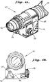
- FIGS. 1A and 1B are illustrations of a night vision scope;
- FIG. 2 is a block diagram illustrating elements of the night vision scope;
- FIG. 3 is an illustration of the elements of an image intensifier in FIG. 2;
- FIG. 4 is a circuit diagram of a voltage source of FIG. 2; and
- FIG. 5 is a circuit diagram showing how components of a night vision scope are supplied power by the voltage source of FIG. 4.
- Reference will now be made in detail to a present preferred embodiment of the invention, an example of which is illustrated in the accompanying drawings.
- A night vision scope utilizing the teachings of the presently preferred embodiment is illustrated in FIG. 1.
Night vision scope 10 intensifies a received image.Night vision scope 10 includes aneye piece 12, alens 14, aninfrared light source 16, and an infraredlight source lens 17. Ahousing 18 contains the electronics and optics required for operation of the invention. Mounted on one face ofhousing 18 is anoperating switch 15 andcap 13 for the single battery which generates a voltage fornight vision scope 10. - The single battery is housed in a battery chamber which includes
cap 13. Thechamber cap 13 is sealed with a standard O-ring. Utilization of an O-ring reduces the complexity and construction costs ofnight scope 10 since an off the shelf element may be used. -
Night vision scope 10 includes a light receiving means for receiving an image. In the present preferred embodiment,lens 14 receives the light image and magnifies it. - The user of
night vision scope 10 places his eye adjacent toeye piece 12 to observe the resultant intensified received image.Infrared light source 16 may be activated to emit infrared light in the direction whichlens 14 is directed. Preferably,infrared light source 16 is an infrared light emitting diode. Afocus lens 17 is mounted onswing arm 19 to be optionally positioned overinfrared light source 16.Lens 17 may be positioned overinfrared light source 16 to focus the infrared light, such as for usinglight source 16 for a spot light. - FIG. 2 illustrates a block diagram of the functional elements of
night vision scope 10. Like reference numerals indicate like structures. Accordingly, FIG. 2 illustratesobjective lens 14 andinfrared light source 16.Night vision scope 10 further includes animage intensifier 20, anoutput window 22 andvoltage source 24.Voltage source 24 supplies the voltage to bothinfrared light source 16 andimage intensifier 20. - An image is received through
lens 14 and transmitted toimage intensifier 20. After image intensification a visible image is output fromimage intensifier 20 tooutput window 22. Observer 26 views the intensified image inoutput window 22. - FIG. 3 illustrates the image intensification process in conjunction with the structural elements of
image intensifier 20.Image intensifier 20 includes aninput window 30, aphoto cathode 32, amicro channel plate 34, and aphosphor screen 36. In a preferred embodiment of the present invention the elements ofimage intensifier 20 are constructed in a wafer tube configuration with the elements being configured as wafers. -
Photo cathode 32 is located betweeninput window 30 andmicro channel plate 34. On the opposite face ofmicro channel plate 34 is locatedphosphor screen 36 at the input tooutput window 22. The eye piece receives the output fromoutput window 22. Anobserver 26 observes an intensified output image througheye piece 12. - During operation of
night vision scope 10 the light fromobject 38 is received throughobjective lens 14. In the presently preferred embodiment,objective lens 14 is a convex lens which gathers light and magnifies the image. Light passes throughinput window 30 ontophotocathode 32.Photocathode 32 responds to the received light by generating a number of electrons in proportion to the intensity of received light. The number of electrons are proportional to the intensity of the received light to form a pattern of electrons corresponding to the received image.Photocathode 32 is sensitive to infrared light as well as light in the visible Spectrum so that electrons are produced in response to infrared light passing through the objective lens and input window ontophotocathode 32. - Electrons from
photocathode 32 are emitted intomicro channel plate 34. The energy of the electrons fromphotocathode 32 is increased because of a voltage applied across the two faces ofmicro channel plate 34.Micro channel plate 34 consists of a disk of optical fibers each of whose primary cylindrical axis is oriented parallel to the direction of received electrons fromphotocathode 32. - The optical fibers in
micro channel plate 34 are held together with reflective cladding between the fibers. Further, each face ofmicro channel plate 34 has an electrode deposited thereon so that a potential may be generated between the two faces to accelerate and energize the electrons entering the optic fibers.Micro channel plate 34 also multiplies the number of electrons by adding additional electrons. - The energized and multiplied electron pattern from
micro channel plate 34 exits the micro channel plate and strikesphosphor screen 36.Phosphor screen 36 generates a visible light image corresponding to the image received throughobjective lens 14.Phosphor screen 36 in the preferred embodiment acts as means for converting the electron pattern generated byphotocathode 32 into a visible light image of the received image. - Since the
objective lens 14 inverts the image of the observedobject 38, input image 40 is upside down during the image intensification process and results in an upside down image on the output ofphosphor screen 36. Accordingly,output image 42 must be inverted forobserver 26. -
Output window 22 transmitsoutput image 42 to eyepiece 12 andobserver 26.Output window 22 is made of optical fiber. In order to invertoutput image 42, the opticalfiber output window 22 is softened and rotated 180° from its origin to the output during manufacture. -
Observer 26 will observe a correctly orientedoutput image 42 througheye piece 12 as avirtual image 44. In this casevirtual image 44 is magnified in size due toobjective lens 14 as well as its light being intensified. - FIG. 4 is a simplified circuit diagram of the
voltage supply 24.Voltage supply 24 includesbattery 50, a step-upcircuit 52, a rectifyingcircuit 54, and a lowbattery indicator circuit 56. Preferably,battery 50 supplies a first voltage of 1.5 V and is a commercially available 1.5 volt battery. - The night vision scope includes a means for supplying a second voltage to the light converting means, the means for increasing the energy of the electrons, and the electron converting means. The second voltage is proportionately greater than the first voltage. In the preferred embodiment of the present invention,
voltage supply circuit 24 produces an output voltage Vout which is greater than the voltage supplied bybattery 50. In the preferred embodiment, voltage Vout is two times the voltage supplied bybattery 50, i.e. 3 volts. Other voltage values and proportions may be used. - The voltage of
battery 50 is input to step-upcircuit 52. Step-up circuit 52 includes an inductor L1 and a switching circuit S1. The output of step-upcircuit 52 is fed to rectifyingcircuit 54. - Step-
up circuit 52 operates by oscillating switch S1 open and closed. When the switch is closed, current builds up in the coil, creating a magnetic field. Next, switch S1 is opened and the magnetic field collapses in inductor L1. Accordingly, the voltage across the inductor reverses polarity. This voltage across the inductor L1 adds to the voltage ofbattery 50 to produce a total voltage which is greater than the voltage produced bybattery 50 alone. - In order to supply a constant voltage at Vout,
rectifier circuit 54 is utilized to smooth out the variations in voltage due to the cycling of switch S1.Rectifier circuit 54 includes diode D1 and capacitor C1.Rectifier circuit 54 works in a conventional manner to smooth out voltage variations at Vout. - A zener diode D2 is included in rectifying
circuit 54 to facilitate utilization of abattery 50 which supplies a voltage greater than the voltage required bynight vision scope 10. Zener diode D2 has an operational value slightly greater than the required voltage. Accordingly, voltage Vout does not exceed a maximum value determined by zener diode D3. Preferably, zener diode is rated as a 3.3 volt zener diode so that the output voltage has a maximum output of 3.3 volts. - For operation of the present preferred embodiment in extremely cold temperatures, the 1.5 volt alkaline battery does not function properly. Therefore, a 3.9 volt lithium battery is used in
voltage supply circuit 24. Output voltage Vout is then limited to a maximum value of 3.3. volts. As the lithium battery wears down below the required output voltage of 3.0 volts, voltage step-up 52 will function to increase the battery voltage as described above. - In order to detect a low voltage condition of battery 50 a low
voltage detecting circuit 56 is provided. This low voltage circuit produces a reference voltage Vout which is compared to the voltage ofbattery 50 bycomparator 58. If the battery voltage is lower than the reference voltage Vref current flows through resistor R1 and through light emitting diode LED1. Accordingly, light emitting diode LED1 will light when the voltage ofbattery 50 goes below Vref. In a preferred embodiment of the invention,battery 50 produces a 1.5 volt output, and Vref Is selected to be 1.17 volts. - In the preferred embodiment of the invention a switching circuit which is used to implement switch S1 is an off the shelf component. In the presently preferred embodiment a Maxim Low Voltage Step-Up DC-DC Convertor, catalog number MAX657 manufactured by Maxim is utilized.
- FIG. 5 illustrates the application of output voltage Vout to the elements of
night vision scope 10 of the presently preferred embodiment. That is, as discussed above, output Vout is applied toimage intensifier 20 and its associated components. The voltage Vout is also applied to provide voltage to an infraredlight source 16 and the light emitting diode (LED) infrared indicator 60. LED infrared indicator 60 indicates the status of infraredlight source 16. That is, infraredlight source 16 can be elected to be either off or on at two different power settings. - Infrared
light source 16 may be selectively activated with switch S2. Ifposition 1 of switch S2 is selected, the infrared light source remains inactive and no infrared light is emitted. If position 2 of switch S2 is chosen, a low power condition of infrared light source is activated and LED infrared indicator 60 indicates this low power status. That is, a low level of infrared light is emitted from infraredlight source 16. This low level of light is generated because of the low level of power supplied through resistor R4 to infraredlight source 16. Further, LED infrared indicator 60 is activated but at a low level due to the amount of power supplied through resistor R3. The LED infrared indicator 60 is located so that it may be viewed througheye piece 12 ofnight vision scope 10. - A high level or high intensity of infrared light will be emitted from infrared
light source 16 if position 3 of switch S2 is selected. The LED infrared indicator 60 will indicate this higher intensity output of infraredlight source 16. The higher intensity of infrared light emitted from infraredlight source 16 will be due to the increased power supplied to infraredlight source 16 through resistor R2. Resistor R2 will be selected to have a lower resistance value than resistor R4 since greater power must flow through resistor R2 for a fixed voltage. Likewise, the resistance of resistor R1 will be chosen to be less than the resistance of resistor R3. - The two different levels of infrared light emitted from infrared
light source 16 allows the user of nightvision night scope 10 to select two different modes of infrared light emission. In the low level mode the user of thenight vision scope 10 can inspect maps with the aid ofimage intensifier 20 at night or do other tasks at close range requiring a low level of illumination. If a higher level of infrared light is required for viewing objects in, for example a room in a house which is dark, the high level of infrared light emitted from infraredlight source 16 may be selected. - It will be apparent to those skilled in the art that various modifications and variations could be made in the night vision scope of the present invention without departing from the scope or spirit of the invention. As an example,
night vision scope 10 may be altered to eliminate the infraredlight source 16 to reduce its cost. Further, the invention may be used in a device that takes the form of a single viewing device with optics for two eyes, or two viewing devices for both eyes.
Claims (9)
- A night vision scope comprising image intensifier means (20), voltage supply means (50) for supplying an energizing voltage for the intensifier, and an infrared light source (16), characterised by an infrared light source control circuit means (S2, R1-R4) coupled between the voltage supply circuit and the infrared source and comprising a resistive voltage dividing arrangement (R2, R4) and a multi-position switch (S2), the switch being arranged in one position to provide illumination of the infrared source with a first voltage level via the voltage dividing arrangement, and in a second position providing a different illumination of the infrared source via the voltage dividing arrangement.
- A scope according to claim 1, wherein the dividing arrangement comprises two resistances (R2, R4) coupled to the source to provide two alternative resistive paths coupled to the switch (S2).
- A scope according to claim 1 or 2 and including a voltage rectifier circuit (D1) for minimizing variations in the voltage output from said voltage supply means (50).
- A scope according to claim 1, 2 or 3 and including limiting circuit means (D2) for limiting the output voltage to a predetermined value.
- A voltage supply circuit according to claim 4, wherein said limiting circuit means includes a zener diode (D2).
- A scope according to claim 4 or 5, wherein said predetermined valve is 3.3 volts.
- A scope according to any one of the preceding claims, wherein the image intensifier means includes:
light converting means for converting the light in an image into electrons in proportion to the intensity of the received light to form a pattern of electrons corresponding to said received image;
energization means for increasing the energy of the electrons in the electron pattern; and
electron converting means for converting the electron pattern into a visible light image of the received image. - A scope according to any one of the preceding claims, wherein the voltage supply means comprises a battery (50).
- A scope according to claim 8, wherein the voltage supply means comprises a substantially cylindrical battery chamber for housing a simple battery, the chamber including a cap and an o-ring for sealing said cap.
Applications Claiming Priority (3)
| Application Number | Priority Date | Filing Date | Title |
|---|---|---|---|
| US07/592,042 US5130527A (en) | 1990-10-03 | 1990-10-03 | Night vision scope with improved voltage supply |
| US592042 | 1990-10-03 | ||
| EP91919511A EP0502186B1 (en) | 1990-10-03 | 1991-09-26 | Night vision scope with improved voltage supply |
Related Parent Applications (1)
| Application Number | Title | Priority Date | Filing Date |
|---|---|---|---|
| EP91919511.5 Division | 1992-04-24 |
Publications (3)
| Publication Number | Publication Date |
|---|---|
| EP0642151A2 true EP0642151A2 (en) | 1995-03-08 |
| EP0642151A3 EP0642151A3 (en) | 1995-05-03 |
| EP0642151B1 EP0642151B1 (en) | 1997-03-19 |
Family
ID=24369036
Family Applications (2)
| Application Number | Title | Priority Date | Filing Date |
|---|---|---|---|
| EP94116461A Expired - Lifetime EP0642151B1 (en) | 1990-10-03 | 1991-09-26 | Night vision scope with voltage supply |
| EP91919511A Expired - Lifetime EP0502186B1 (en) | 1990-10-03 | 1991-09-26 | Night vision scope with improved voltage supply |
Family Applications After (1)
| Application Number | Title | Priority Date | Filing Date |
|---|---|---|---|
| EP91919511A Expired - Lifetime EP0502186B1 (en) | 1990-10-03 | 1991-09-26 | Night vision scope with improved voltage supply |
Country Status (7)
| Country | Link |
|---|---|
| US (1) | US5130527A (en) |
| EP (2) | EP0642151B1 (en) |
| KR (1) | KR100240804B1 (en) |
| GR (2) | GR3020435T3 (en) |
| IL (1) | IL99593A (en) |
| SG (2) | SG42978A1 (en) |
| WO (1) | WO1992006485A1 (en) |
Cited By (1)
| Publication number | Priority date | Publication date | Assignee | Title |
|---|---|---|---|---|
| WO2005018023A3 (en) * | 2003-02-05 | 2005-07-14 | Itt Mfg Enterprises Inc | Single battery housing assembly |
Families Citing this family (17)
| Publication number | Priority date | Publication date | Assignee | Title |
|---|---|---|---|---|
| USD349510S (en) | 1992-01-28 | 1994-08-09 | Asia Optical Co., Ltd. | Sight scope |
| US5703354A (en) * | 1996-02-28 | 1997-12-30 | Litton Systems, Inc. | Binocular night vision device and method of making and using the device |
| US6215232B1 (en) | 1996-03-05 | 2001-04-10 | Litton Systems, Inc. | Microchannel plate having low ion feedback, method of its manufacture, and devices using such a microchannel plate |
| DE69626690T2 (en) * | 1996-10-17 | 2003-12-24 | Simrad Optronics A/S, Oslo | Night vision device with operation of focusing and power supply through a common handle |
| US6043842A (en) * | 1996-12-31 | 2000-03-28 | Olympus America Inc. | Remote surveillance device |
| US5883381A (en) * | 1997-07-28 | 1999-03-16 | Saldana; Michael R. | Night vision device having series regulator in power supply for MCP voltage control |
| US6087660A (en) * | 1997-11-14 | 2000-07-11 | Litton Systems, Inc. | Night vision device and method |
| US5937562A (en) * | 1997-11-17 | 1999-08-17 | Henry Technical Services, Incorporated | Optical accessory |
| US6449419B1 (en) | 2000-09-05 | 2002-09-10 | Richard Brough | Optical viewing system and clamping device therefor |
| US6667472B2 (en) * | 2001-07-20 | 2003-12-23 | Itt Manufacturing Enterprises, Inc. | Night vision device with antireflection coating on cathode window |
| US6806683B2 (en) * | 2002-02-05 | 2004-10-19 | Litton Systems, Inc. | Battery adapter for night vision device |
| USD515118S1 (en) * | 2002-10-04 | 2006-02-14 | Gs Development | Sight with a light emitting device |
| KR100528985B1 (en) * | 2003-03-06 | 2005-11-22 | (주)이오시스템 | power supply and night vision device using the power supply |
| EP1668892A2 (en) * | 2003-09-23 | 2006-06-14 | Richard Brough | Optical viewing system and adaptor therefor |
| USD533573S1 (en) * | 2005-10-19 | 2006-12-12 | Insight Technology, Inc. | Monocular |
| US7576515B2 (en) * | 2007-04-03 | 2009-08-18 | Knight's Armament Co. | Battery adapter system and night-vision scope using same |
| KR20110068070A (en) * | 2009-12-15 | 2011-06-22 | 삼성전기주식회사 | Low Light Imaging Device Using Silicon Photoelectric Multiplier |
Family Cites Families (7)
| Publication number | Priority date | Publication date | Assignee | Title |
|---|---|---|---|---|
| EP0094581A1 (en) * | 1982-05-17 | 1983-11-23 | Wild Heerbrugg Ag. | Binocular night viewing system |
| GB2156541B (en) * | 1984-03-23 | 1987-07-22 | Philips Electronic Associated | Graticule illuminator for a night sight |
| US4755725A (en) * | 1985-12-12 | 1988-07-05 | Varo, Inc. | High intensity light shut-down circuit for night vision goggle |
| US4728786A (en) * | 1985-11-15 | 1988-03-01 | American Sterilizer Company | Stereo image intensifier |
| US4672194A (en) * | 1985-12-12 | 1987-06-09 | Varo, Inc. | Passive proximity battery control circuit for night vision goggles |
| US4734573A (en) * | 1986-07-14 | 1988-03-29 | Eol3 Company, Inc. | Image intensifier with additional power supply |
| US4794246A (en) * | 1987-07-10 | 1988-12-27 | Varo, Inc. | Universal passive night vision system |
-
1990
- 1990-10-03 US US07/592,042 patent/US5130527A/en not_active Expired - Lifetime
-
1991
- 1991-09-26 SG SG1996001689A patent/SG42978A1/en unknown
- 1991-09-26 KR KR1019920701296A patent/KR100240804B1/en not_active Expired - Fee Related
- 1991-09-26 EP EP94116461A patent/EP0642151B1/en not_active Expired - Lifetime
- 1991-09-26 SG SG1996001480A patent/SG47001A1/en unknown
- 1991-09-26 EP EP91919511A patent/EP0502186B1/en not_active Expired - Lifetime
- 1991-09-26 WO PCT/US1991/007038 patent/WO1992006485A1/en not_active Ceased
- 1991-09-27 IL IL9959391A patent/IL99593A/en not_active IP Right Cessation
-
1996
- 1996-07-02 GR GR960401808T patent/GR3020435T3/en unknown
-
1997
- 1997-04-22 GR GR970400925T patent/GR3023260T3/en unknown
Cited By (4)
| Publication number | Priority date | Publication date | Assignee | Title |
|---|---|---|---|---|
| WO2005018023A3 (en) * | 2003-02-05 | 2005-07-14 | Itt Mfg Enterprises Inc | Single battery housing assembly |
| US7049027B2 (en) | 2003-02-05 | 2006-05-23 | Itt Manufacturing Enterprises, Inc. | Single battery housing assembly |
| AU2004298276B2 (en) * | 2003-02-05 | 2008-11-20 | Elbit Systems Of America, Llc | Single battery housing assembly |
| AU2004298276B8 (en) * | 2003-02-05 | 2009-11-19 | Elbit Systems Of America, Llc | Single battery housing assembly |
Also Published As
| Publication number | Publication date |
|---|---|
| AU8485791A (en) | 1992-04-09 |
| EP0502186A1 (en) | 1992-09-09 |
| AU646087B2 (en) | 1994-02-10 |
| EP0642151A3 (en) | 1995-05-03 |
| GR3023260T3 (en) | 1997-07-30 |
| US5130527A (en) | 1992-07-14 |
| SG42978A1 (en) | 1997-10-17 |
| EP0502186B1 (en) | 1996-06-19 |
| EP0502186A4 (en) | 1993-03-03 |
| IL99593A (en) | 1994-02-27 |
| KR100240804B1 (en) | 2000-01-15 |
| EP0642151B1 (en) | 1997-03-19 |
| WO1992006485A1 (en) | 1992-04-16 |
| SG47001A1 (en) | 1998-03-20 |
| GR3020435T3 (en) | 1996-10-31 |
| IL99593A0 (en) | 1992-08-18 |
Similar Documents
| Publication | Publication Date | Title |
|---|---|---|
| EP0642151B1 (en) | Night vision scope with voltage supply | |
| US5396069A (en) | Portable monocular night vision apparatus | |
| US5903996A (en) | Day/night viewing device with laser range finder utilizing two wavelengths of laser light, and method of its operation | |
| US4707595A (en) | Invisible light beam projector and night vision system | |
| US5867313A (en) | Multipurpose night vision monocular | |
| JP3391458B2 (en) | Monocular night vision device | |
| US4627171A (en) | Reticle illuminator | |
| JPH033206B2 (en) | ||
| USRE33572E (en) | Invisible light beam projector and night vision system | |
| SE513594C2 (en) | Device at an optical sight with illuminated benchmark | |
| US6512887B2 (en) | Flash lamps for underwater photography provided with target light and control methods and devices therefor | |
| KR970003768B1 (en) | Battery control circuit | |
| US4494851A (en) | Display unit for flashlight photography | |
| US6072565A (en) | Night vision device with improved laser range finder | |
| US4159170A (en) | Camera position indicator device | |
| CN118140168A (en) | Night vision device with integrated display | |
| RU2104485C1 (en) | Laser target indicator-range finder | |
| GB2166259A (en) | Image intensifier system operated in a pulsed manner | |
| RU2040805C1 (en) | Optical sighting device | |
| SU824278A1 (en) | Device for burning-through protecting of cathode-ray tube | |
| JPH035895Y2 (en) | ||
| RU2275651C2 (en) | Observation and target indication electro-optic system | |
| JPS5865417A (en) | Dark viewer | |
| CA2331424C (en) | Night viewer and laser range finder | |
| JPS6411245A (en) | Camera with field image display |
Legal Events
| Date | Code | Title | Description |
|---|---|---|---|
| PUAI | Public reference made under article 153(3) epc to a published international application that has entered the european phase |
Free format text: ORIGINAL CODE: 0009012 |
|
| AC | Divisional application: reference to earlier application |
Ref document number: 502186 Country of ref document: EP |
|
| AK | Designated contracting states |
Kind code of ref document: A2 Designated state(s): GB GR |
|
| PUAL | Search report despatched |
Free format text: ORIGINAL CODE: 0009013 |
|
| AK | Designated contracting states |
Kind code of ref document: A3 Designated state(s): GB GR |
|
| RIN1 | Information on inventor provided before grant (corrected) |
Inventor name: MORRIS, TERRY D. Inventor name: GRAMER, MARK EVERETT |
|
| 17P | Request for examination filed |
Effective date: 19951026 |
|
| GRAG | Despatch of communication of intention to grant |
Free format text: ORIGINAL CODE: EPIDOS AGRA |
|
| GRAH | Despatch of communication of intention to grant a patent |
Free format text: ORIGINAL CODE: EPIDOS IGRA |
|
| 17Q | First examination report despatched |
Effective date: 19960709 |
|
| GRAH | Despatch of communication of intention to grant a patent |
Free format text: ORIGINAL CODE: EPIDOS IGRA |
|
| RAP1 | Party data changed (applicant data changed or rights of an application transferred) |
Owner name: LITTON SYSTEMS, INC. |
|
| GRAA | (expected) grant |
Free format text: ORIGINAL CODE: 0009210 |
|
| AC | Divisional application: reference to earlier application |
Ref document number: 502186 Country of ref document: EP |
|
| AK | Designated contracting states |
Kind code of ref document: B1 Designated state(s): GB GR |
|
| REG | Reference to a national code |
Ref country code: GR Ref legal event code: FG4A Free format text: 3023260 |
|
| PLBE | No opposition filed within time limit |
Free format text: ORIGINAL CODE: 0009261 |
|
| STAA | Information on the status of an ep patent application or granted ep patent |
Free format text: STATUS: NO OPPOSITION FILED WITHIN TIME LIMIT |
|
| 26N | No opposition filed | ||
| PGFP | Annual fee paid to national office [announced via postgrant information from national office to epo] |
Ref country code: GR Payment date: 19990730 Year of fee payment: 9 |
|
| PG25 | Lapsed in a contracting state [announced via postgrant information from national office to epo] |
Ref country code: GR Free format text: LAPSE BECAUSE OF NON-PAYMENT OF DUE FEES Effective date: 20000930 |
|
| REG | Reference to a national code |
Ref country code: GB Ref legal event code: IF02 |
|
| PGFP | Annual fee paid to national office [announced via postgrant information from national office to epo] |
Ref country code: GB Payment date: 20100921 Year of fee payment: 20 |
|
| REG | Reference to a national code |
Ref country code: GB Ref legal event code: 732E Free format text: REGISTERED BETWEEN 20110414 AND 20110420 |
|
| REG | Reference to a national code |
Ref country code: GB Ref legal event code: PE20 Expiry date: 20110925 |
|
| PG25 | Lapsed in a contracting state [announced via postgrant information from national office to epo] |
Ref country code: GB Free format text: LAPSE BECAUSE OF EXPIRATION OF PROTECTION Effective date: 20110925 |