EP0640524B1 - Method for injecting payloads into orbit - Google Patents
Method for injecting payloads into orbit Download PDFInfo
- Publication number
- EP0640524B1 EP0640524B1 EP94112788A EP94112788A EP0640524B1 EP 0640524 B1 EP0640524 B1 EP 0640524B1 EP 94112788 A EP94112788 A EP 94112788A EP 94112788 A EP94112788 A EP 94112788A EP 0640524 B1 EP0640524 B1 EP 0640524B1
- Authority
- EP
- European Patent Office
- Prior art keywords
- orbit
- vehicle
- payload
- firing
- upper stage
- Prior art date
- Legal status (The legal status is an assumption and is not a legal conclusion. Google has not performed a legal analysis and makes no representation as to the accuracy of the status listed.)
- Expired - Lifetime
Links
Images


Classifications
-
- B—PERFORMING OPERATIONS; TRANSPORTING
- B64—AIRCRAFT; AVIATION; COSMONAUTICS
- B64G—COSMONAUTICS; VEHICLES OR EQUIPMENT THEREFOR
- B64G1/00—Cosmonautic vehicles
- B64G1/22—Parts of, or equipment specially adapted for fitting in or to, cosmonautic vehicles
- B64G1/24—Guiding or controlling apparatus, e.g. for attitude control
- B64G1/242—Orbits and trajectories
- B64G1/2427—Transfer orbits
-
- B—PERFORMING OPERATIONS; TRANSPORTING
- B64—AIRCRAFT; AVIATION; COSMONAUTICS
- B64G—COSMONAUTICS; VEHICLES OR EQUIPMENT THEREFOR
- B64G1/00—Cosmonautic vehicles
- B64G1/22—Parts of, or equipment specially adapted for fitting in or to, cosmonautic vehicles
- B64G1/24—Guiding or controlling apparatus, e.g. for attitude control
- B64G1/242—Orbits and trajectories
- B64G1/2425—Geosynchronous orbits
-
- B—PERFORMING OPERATIONS; TRANSPORTING
- B64—AIRCRAFT; AVIATION; COSMONAUTICS
- B64G—COSMONAUTICS; VEHICLES OR EQUIPMENT THEREFOR
- B64G1/00—Cosmonautic vehicles
- B64G1/002—Launch systems
Definitions
- the invention relates to a method for injecting payloads into orbit, and more particularly, to a method employing a suborbital trajectory instead of a conventional parking orbit and wherein the final launch booster burn for injection into a desired elliptical orbit, for example, a geosynchronous transfer orbit ("geo-transfer orbit” or "GTO”), is non-apsidal (i.e., does not occur at the apogee or perigee of that orbit) and occurs while the flight path angle is either negative or positive.
- GTO geosynchronous transfer orbit
- orbital trajectories can utilize this method, including: (1) geo-transfer orbits; (2) "Molniya" orbits or other elliptical orbits having a specified initial position of the line of apsides; and (3) any trajectories requiring significantly lower inclinations than their launch site latitudes.
- geo-transfer orbits is used as the primary example in this specification, those skilled in the art will appreciate the method's application to the other types of orbital trajectories.
- the process of injecting a payload into orbit with a multi-stage launch booster vehicle has several constraints.
- the booster must provide sufficient energy or velocity to reach orbital conditions and, if the desired orbit is elliptical, it may be desirable to place the line of apsides (i.e., the line connecting orbit apogee and perigee) at a specific initial location.
- the line of apsides i.e., the line connecting orbit apogee and perigee
- the line of apsides be at or near the equator. This is because the burn performed at apogee often needs to combine the orbit raising maneuver to geosynchronous altitude with an inclination change maneuver to achieve 0° inclination (geo-stationary orbit), as illustrated in FIGS. 1 and 2A.
- Molniya-type orbits are another example of orbits with respect to which it is desirable to place the line of apsides at a specific location.
- the Molniya orbits are highly elliptical and inclined 63.4°, which is a unique inclination in that the line of apsides does not rotate -- i.e., apogee and perigee remain at the same latitude.
- These orbits often are used where long periods of satellite operation are desired over the northern hemisphere --i.e., apogee over the northern hemisphere. This requires that perigee be placed in the southern hemisphere, typically at a latitude of 63.4° south.
- the maximum energy change for a fixed amount of velocity change is created by adding the velocity at perigee of the final orbit. For this reason, it usually is desirable to inject into an elliptical orbit at perigee of that orbit.
- an optimal booster trajectory often does not leave the last stage burnout condition at perigee.
- the desired perigee for these cases is usually very far downrange (e.g., equator or 63.4° south) from an efficient booster burnout position. This is particularly true for launches from the United States where the burnout location is often greater than 25° north for geo-transfer orbits, or in the northern hemisphere for Molniya orbits.
- the traditional trajectory design uses a parking orbit (i.e., a temporary orbit of essentially constant altitude) to coast to the desired perigee location to perform the final stage burn.
- the mission profile and orbit geometry of a launch trajectory to a geosynchronous orbit employing a conventional parking orbit 30 are shown, respectively, in FIGS. 1 and 2A.
- the booster places the payload and the last stage, often called a perigee kick motor ("PKM"), into the parking orbit.
- PPM perigee kick motor
- the upper stage size (propellant load, total impulse, etc.) is defined primarily by the size of the payload, the ⁇ V desired and the parking orbit selected. Other factors such as stage burnout weight and specific impulse are also variable factors, but these are motor technology parameters that do not qualitatively change much from design to design.
- PKM's are often solid rocket motors due to their superior mass fraction; however, they generally are available only in discrete sizes. If the theoretical PKM size that matches the payload and optimal parking orbit is not available, there are several alternatives. If the propellant required is slightly below an "off-the-shelf" size, often the propellant can be machined out (i.e., off-loaded), reducing the total impulse.
- a first object of the invention is to allow lower stages to boost heavier upper stages to the desired upper stage or PKM burn location than is possible following a trajectory that includes a conventional parking orbit.
- a resulting object is to allow booster stages to carry larger payloads into orbit than is possible using prior methods.
- a further object is to eliminate or reduce the requirement to off-load propellant from upper stages that are too large to inject into a typical parking orbit conventionally required to reach the desired burn location of the upper stage.
- a vehicle before a vehicle is injected into a desired elliptical orbit, it is placed in a lower altitude parking orbit. The vehicle then coasts downrange to the perigee of the desired elliptical orbit, where the PKM is burned to insert the vehicle payload into such orbit.
- the "larger" upper stage coasts to the injection point (i.e., location at which the upper stage burn occurs to inject the vehicle payload into the desired elliptical orbit) on a suborbital, "pseudo-parking orbit" trajectory.
- the vehicle reaches a higher altitude than the typical parking orbit altitude. Because this trajectory is suborbital, the vehicle falls back toward the Earth to a point where the upper stage or PKM is burned to insert the vehicle into the elliptical orbit.
- the trajectory of the vehicle is decreasing in altitude throughout the firing of the upper stage engine.
- the PKM is burned above a minimum altitude (approximately 100 nm) to avoid excessive free molecular heating of the vehicle.
- This PKM burn is non-apsidal -i.e., it does not occur near either apogee or perigee of the elliptical orbit.
- the method of the present invention allows the placement of the perigee wherever desired, allows the use of larger upper stages (thereby reducing or eliminating the need to off-load the motor), and improves performance.
- non-apsidal trajectory of the present invention is carried out by firing rocket booster engines at non-zero flight path angles and at slightly higher altitudes than would be the case for trajectories using a conventional parking orbit, acceptable performance is achieved because a larger PKM can be used.
- the larger PKM provides the additional energy that makes up for the non-optimal aspects of this trajectory and permits the final elliptical orbit to have the desired perigee location.
- the PKM is burned before apogee of the suborbital trajectory there the flight path angle is positive to inject the payload into the elliptical orbit at a location downrange from perigee of the elliptical orbit.
- the trajector of the vehicle is increasing in altitude throughout the firing of the upper stage engine.
- the firing of the upper stage engine occurs at apogee of the suborbital trajectory.
- the initial portion of the launch trajectory of the present invention is the same as trajectories employing a conventional parking orbit.
- a typical launch booster vehicle (not shown) having three lower stages and an upper stage or PKM
- the vehicle carrying the payload is launched from the Earth 8 at a launch site 10 by firing the first stage of the launch vehicle.
- the method of the present invention is described in terms of a launch booster vehicle having four stages -- three lower stages and an upper stage -- depending upon launch vehicle design and mission requirements, the number of stages utilized could vary.
- stage 1 has completed its burn
- the second stage is fired at location 12 on the trajectory.
- stage 2 has completed its burn conventionally at location 14a
- the method of the present invention departs from that where a conventional parking orbit is used.
- the final lower stage engine i.e., stage 3 in the example shown in FIGS. 1 and 2A
- stage 3 in the example shown in FIGS. 1 and 2A
- the burn of this final lower stage engine is sufficient to place the vehicle with its payload into the desired parking orbit 30 , typically having an altitude of about 90 to 110 nautical miles.
- the PKM then burns from location 17a to location 18a to achieve insertion into the elliptical orbit.
- the final lower stage engine i.e., stage 3 in the example
- stage 3 the final lower stage engine
- the flight path angle is positive throughout the firing of the final lower stage booster in order to increase the altitude of the apogee and correspondingly decrease the perigee of the intermediate suborbital trajectory 36 .
- This is illustrated by the curves showing the relationship between altitude and range from the launch site in FIG. 3 for a conventional parking orbit and FIG. 4 for the non-apsidal trajectory of the present invention.
- the higher apogee allows the vehicle to coast much farther downrange before another rocket burn is required, but it is not necessary to coast all the way down to the desired perigee location before firing the upper stage (i.e., the PKM, although with the method of the present invention it is not fired at perigee) to boost the vehicle and payload into the desired elliptical orbit.
- the vehicle reaches a peak altitude (i.e., apogee) in its suborbital trajectory 36 at point 22 , beyond which the vehicle loses altitude.
- the shape of the suborbital trajectory 36 is selected so as to have a location at which the firing of the upper stage provides the additional energy needed to reach the desired final elliptical orbit (e.g., geosynchronous transfer orbit 32 in FIG. 2B) having the perigee at the desired location.
- the upper stage is fired over a portion of the suborbital trajectory from 17b to 18b where the flight path angle is negative.
- the upper stage is burned over a portion of the trajectory ending at location 18b substantially before the vehicle is over the equator.
- the final elliptical orbit can be, for example, a geosynchronous transfer orbit 32 , which is a type known in the art and which is the same for both the method of the present invention and methods employing a conventional parking orbit, as illustrated in FIGS. 2A and 2B.
- the final orbital destination is a geosynchronous orbit 34 . Insertion into geosynchronous orbit 34 occurs at location 20a in the conventional method. Similarly, insertion into geosynchronous orbit 34 occurs at location 20b for the orbit geometry depicted in FIG. 2B.
- the suborbital trajectory of the present invention enables a larger initial mass to be placed at the desired injection point, thereby allowing a larger upper stage rocket engine to be used, which results in the ability to inject larger payloads into the desired orbits.
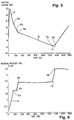
- FIG. 5 is a graph depicting the flight path angle (i.e., inertial gamma) of the launch booster vehicle during the launch sequence.
- the flight path angle of a vehicle flying directly away from or parallel to the Earth's surface is 90° or 0°, respectively.
- the inertial velocity while sitting on the launch pad is non-zero due to the rotation of the Earth.
- the inertial gamma is zero because this velocity is parallel to the Earth's surface.
- the vehicle lifts off the inertial velocity vector gets larger and inertial gamma increases as vertical and downrange speed is added. Later in the trajectory inertial gamma decreases as the velocity vector again becomes close to parallel to the Earth's surface.
- the lower stages of the launch booster vehicle are burned, its flight path angle decreases until a location (location 19 in FIG. 5) on the trajectory following the firing of the upper stage or PKM.
- the stage 3 engine burns out, and the vehicle begins to coast in its suborbital trajectory. Because the vehicle speed at this point is less than required for circular orbit at this altitude, the force of the Earth's gravity on the vehicle decreases the vehicle's flight path angle and eventually causes the vehicle to fall back toward the Earth 8 . When the vehicle is falling toward the Earth 8 in its suborbital trajectory, its flight path angle is negative.
- the graph in FIG. 6 shows the inertial velocity of the launch booster vehicle during the launch sequence.
- the inertial velocity steadily increases while the first two stages are burned.
- the vehicle coasts, and its inertial velocity slightly decreases.
- stage 3 is ignited, and its thrust causes the inertial velocity to increase again.
- the vehicle coasts in its suborbital trajectory, with velocity being converted to gravitational potential energy and then back to kinetic energy once past apogee causing only small changes in inertial velocity.
- PKM ignition gives the inertial velocity another boost.
- the inertial velocity levels off when the PKM is burned out, again only changing as kinetic energy becomes gravitational potential energy.
Landscapes
- Engineering & Computer Science (AREA)
- Remote Sensing (AREA)
- Chemical & Material Sciences (AREA)
- Combustion & Propulsion (AREA)
- Radar, Positioning & Navigation (AREA)
- Aviation & Aerospace Engineering (AREA)
- Aiming, Guidance, Guns With A Light Source, Armor, Camouflage, And Targets (AREA)
- Control Of Position, Course, Altitude, Or Attitude Of Moving Bodies (AREA)
- Navigation (AREA)
Description
Claims (10)
- A method for injecting a payload into an elliptical orbit having its line of apsides at a specific initial location comprising the steps of:firing at least one lower stage engine of a rocket booster vehicle carrying the payload so as to launch the rocket booster vehicle and payload along a suborbital trajectory;allowing the vehicle to coast downrange in the suborbital trajectory; andfiring an upper stage engine of the rocket booster vehicle to cause the payload to be injected into the elliptical orbit, characterized in that the location at which firing of the upper stage engine is commenced is not at or near perigee of the elliptical orbit, nor at or near apogee of the elliptical orbit.
- The method of claim 1 wherein the flight path angle of the rocket booster vehicle is positive along a first portion of the suborbital trajectory along which the at least one lower stage engine is fired, and is negative along a second portion of the suborbital trajectory, along which the upper stage engine commences firing.
- The method of claim 2 wherein the flight path angle of the rocket booster vehicle is negative throughout the firing of the upper stage engine.
- The method of claim 3 wherein the thrust of the upper stage engine is pointed substantially along the velocity vector of the rocket booster vehicle throughout the firing of the upper stage engine.
- The method of claim 3 wherein the flight path angle of the rocket booster vehicle is more negative when firing of the upper stage engine is commenced than when it is completed.
- The method of claim 3 wherein the firing of the upper stage engine is completed above a minimum altitude whereby excessive free molecular heating of the vehicle is avoided.
- The method of claims 1 to 6 wherein the perigee of the elliptical orbit is downrange from the location at which the payload is injected into the elliptical orbit.
- The method of claims 1 to 6 wherein the perigee of the elliptical orbit is up range from the location at which the payload is injected into the elliptical orbit.
- The method of claims 1 to 8 wherein the elliptical orbit is a geosynchronous transfer orbit.
- The method of claims 1 to 8 wherein the elliptical orbit is a Molniya orbit.
Applications Claiming Priority (2)
| Application Number | Priority Date | Filing Date | Title |
|---|---|---|---|
| US111095 | 1993-08-24 | ||
| US08/111,095 US5681011A (en) | 1993-08-24 | 1993-08-24 | Method for injecting payloads into orbit |
Publications (2)
| Publication Number | Publication Date |
|---|---|
| EP0640524A1 EP0640524A1 (en) | 1995-03-01 |
| EP0640524B1 true EP0640524B1 (en) | 1999-10-13 |
Family
ID=22336570
Family Applications (1)
| Application Number | Title | Priority Date | Filing Date |
|---|---|---|---|
| EP94112788A Expired - Lifetime EP0640524B1 (en) | 1993-08-24 | 1994-08-16 | Method for injecting payloads into orbit |
Country Status (2)
| Country | Link |
|---|---|
| US (1) | US5681011A (en) |
| EP (1) | EP0640524B1 (en) |
Cited By (1)
| Publication number | Priority date | Publication date | Assignee | Title |
|---|---|---|---|---|
| CN109460049A (en) * | 2018-11-14 | 2019-03-12 | 北京控制工程研究所 | Geo-synchronous orbit satellite apogee orbit changing method based on inertia directing mode |
Families Citing this family (23)
| Publication number | Priority date | Publication date | Assignee | Title |
|---|---|---|---|---|
| FR2747102B1 (en) * | 1996-04-05 | 1998-06-26 | Europ Propulsion | METHOD AND SYSTEM FOR ORBITTING A SPACE VEHICLE WITH HIGH SPECIFIC PULSE PROPELLERS |
| FR2757825B1 (en) * | 1996-12-31 | 1999-03-26 | Europ Propulsion | METHOD AND SYSTEM FOR SIMULTANEOUSLY LAUNCHING SATELLITES ON NON-COPLANAR ORBITS USING VERY ECCENTRIC ORBITES AND ATMOSPHERIC BRAKING |
| FR2757824B1 (en) * | 1996-12-31 | 1999-03-26 | Europ Propulsion | METHOD AND SYSTEM FOR LAUNCHING SATELLITES ON NON-COPLANAR ORBITS USING LUNAR GRAVITATIONAL ASSISTANCE |
| WO1998033704A2 (en) | 1997-02-04 | 1998-08-06 | Belbruno Edward A | Computer implemented procedure for ballistic capture transfer |
| WO1998042570A2 (en) * | 1997-03-25 | 1998-10-01 | Belbruno Edward A | Method for changing inclinations of orbiting satellites |
| US6097997A (en) * | 1997-03-25 | 2000-08-01 | Galaxy Development, Llc | Low energy method for changing the inclinations of orbiting satellites using weak stability boundaries and a computer process for implementing same |
| EA002665B1 (en) * | 1997-04-24 | 2002-08-29 | Галакси Девелопмент, Ллс | METHOD OF CHANGING THE INCIDENCE AND HEIGHT OF THE ORBIT OF A SPACE AIRCRAFT WITH THE USE OF THE LIMITS OF THE SMALL SUSTAINABILITY |
| FR2768399B1 (en) * | 1997-09-12 | 1999-11-12 | Aerospatiale | METHOD FOR SETTING AN ARTIFICIAL SATELLITE TO GEOSTATIONARY ORBIT |
| US6385512B1 (en) | 1999-04-16 | 2002-05-07 | Galaxy Development Llc | System and method of a ballistic capture transfer to L4, L5 |
| US7113851B1 (en) * | 1999-06-09 | 2006-09-26 | Walter Gelon | Practical orbit raising system and method for geosynchronous satellites |
| US6315248B1 (en) * | 2000-02-10 | 2001-11-13 | The United States Of America As Represented By The Secretary Of The Navy | Method for satellite injection using a solid fuel rocket motor |
| GB2388578A (en) * | 2002-05-18 | 2003-11-19 | Astrium Ltd | Satellite launch vehicles and a method of launching satellites into orbit |
| US8534598B2 (en) * | 2006-10-12 | 2013-09-17 | Robert Salkeld | Direct flight far space shuttle |
| US7840180B2 (en) * | 2006-12-22 | 2010-11-23 | The Boeing Company | Molniya orbit satellite systems, apparatus, and methods |
| US8016240B2 (en) * | 2007-03-29 | 2011-09-13 | The Boeing Company | Satellites and satellite fleet implementation methods and apparatus |
| US8768622B2 (en) * | 2012-09-14 | 2014-07-01 | The United States Of America, As Represented By The Secretary Of The Navy | System and method for maneuver plan for satellites flying in proximity using apocentral coordinate system |
| US9139311B2 (en) | 2013-03-15 | 2015-09-22 | Robert Salkeld | Reusable global launcher |
| US9284068B2 (en) * | 2014-04-08 | 2016-03-15 | The Boeing Company | Fast-low energy transfer to Earth-Moon Lagrange point L2 |
| FR3020348B1 (en) * | 2014-04-24 | 2016-05-13 | Snecma | METHOD FOR DEPLOYING A CONSTELLATION OF SATELLITES |
| FR3024128B1 (en) * | 2014-07-25 | 2016-07-22 | Thales Sa | METHOD OF POSTING A SATELLITE AND TESTING ORBIT OF ITS USEFUL LOAD |
| EP3015369B1 (en) * | 2014-10-30 | 2019-04-17 | Airbus Defence and Space Limited | Space debris interception |
| US9919813B2 (en) | 2015-04-15 | 2018-03-20 | The United States Of America, As Represented By The Secretary Of The Navy | Control system and method for a plane change for satellite operations |
| CN115906277B (en) * | 2022-11-03 | 2025-12-16 | 上海宇航系统工程研究所 | Design method for carrier rocket plus upper-layer cascade connection track |
Family Cites Families (14)
| Publication number | Priority date | Publication date | Assignee | Title |
|---|---|---|---|---|
| FR2569162A1 (en) * | 1977-11-25 | 1986-02-21 | Ford Aerospace & Communication | METHOD FOR ORBITTING SATELLITES AND SPACE VESSELS |
| US4943014A (en) * | 1979-10-30 | 1990-07-24 | Trw Inc. | Soft ride method for changing the altitude or position of a spacecraft in orbit |
| US4618112A (en) * | 1983-04-15 | 1986-10-21 | Rca Corporation | Spacecraft angular momentum stabilization system and method |
| US4657210A (en) * | 1985-05-17 | 1987-04-14 | Rca Corporation | Spacecraft stabilization system and method |
| US4741502A (en) * | 1985-10-01 | 1988-05-03 | Hughes Aircraft Company | Method and apparatus for launching a spacecraft by use of a recoverable upper rocket stage |
| WO1990001447A1 (en) * | 1988-08-12 | 1990-02-22 | Nippon Telegraph And Telephone Corporation | Method and apparatus for changing orbit of artificial satellite |
| US4964340A (en) * | 1988-10-07 | 1990-10-23 | Space Services, Incorporated | Overlapping stage burn for multistage launch vehicles |
| FR2647565B1 (en) * | 1989-04-24 | 1991-07-26 | Alcatel Espace | METHOD FOR POSTING A GEOSTATIONARY TELECOMMUNICATIONS SATELLITE |
| FR2650135B1 (en) * | 1989-07-19 | 1994-05-20 | Centre Nal Etudes Spatiales | SATELLITE AND METHOD OF ORBITTING BY GRAVITATIONAL ASSISTANCE |
| US5143328A (en) * | 1989-10-05 | 1992-09-01 | Leonard Byron P | Launch vehicle with reconfigurable interstage propellant manifolding and solid rocket boosters |
| US5242135A (en) * | 1990-01-30 | 1993-09-07 | Scott David R | Space transfer vehicle and integrated guidance launch system |
| US5186419A (en) * | 1990-01-30 | 1993-02-16 | Scott David R | Space transfer vehicle and integrated guidance launch system |
| US5090642A (en) * | 1990-02-20 | 1992-02-25 | Salkeld Robert J | Projectile delivery system |
| US5158249A (en) * | 1990-10-12 | 1992-10-27 | Ball Corporation | Orbital systems for cislunar travel |
-
1993
- 1993-08-24 US US08/111,095 patent/US5681011A/en not_active Expired - Lifetime
-
1994
- 1994-08-16 EP EP94112788A patent/EP0640524B1/en not_active Expired - Lifetime
Non-Patent Citations (1)
| Title |
|---|
| Mark R. Goodell, Thesis "Analysis of Suborbital Launch Trajectories for Satellite Delivery" (AFIT/GA/ENY/91D-8) Air Force Institute of Technology, December 1991 * |
Cited By (2)
| Publication number | Priority date | Publication date | Assignee | Title |
|---|---|---|---|---|
| CN109460049A (en) * | 2018-11-14 | 2019-03-12 | 北京控制工程研究所 | Geo-synchronous orbit satellite apogee orbit changing method based on inertia directing mode |
| CN109460049B (en) * | 2018-11-14 | 2021-11-16 | 北京控制工程研究所 | Geosynchronous orbit satellite apogee orbit transfer method based on inertial pointing mode |
Also Published As
| Publication number | Publication date |
|---|---|
| EP0640524A1 (en) | 1995-03-01 |
| US5681011A (en) | 1997-10-28 |
Similar Documents
| Publication | Publication Date | Title |
|---|---|---|
| US5681011A (en) | Method for injecting payloads into orbit | |
| EP0673833B1 (en) | Optimal transfer orbit trajectory using electric propulsion | |
| US4964340A (en) | Overlapping stage burn for multistage launch vehicles | |
| US5511748A (en) | Method for extending the useful life of a space satellite | |
| RU2161108C1 (en) | Method for orbit injection of payload by multifunctional launch vehicle of combination arrangement with cruise liquid- propellant rocket engine installations (lrei), multifunctional launch vehicle with cruise lpei and method for its development | |
| JPH1029599A (en) | Method and apparatus for placing a spacecraft in a target orbit | |
| EP0825508A1 (en) | Satellite co-location methods | |
| US5568904A (en) | Steered perigee velocity augmentation | |
| US6059235A (en) | Interplanetary transfer method | |
| CN117208231B (en) | GEO satellite minimum orbit height calculation method based on satellite propellant constraint | |
| JPH0215440B2 (en) | ||
| McDonald | Solid rockets-An affordable solution to future space propulsion needs | |
| DUGAN | Supply and resupply of stations in synchronous orbit | |
| Kennedy et al. | Summary of the Bimodal Satellite Mission Study | |
| MULLER | The Slinger-An in-orbit booster facility | |
| Thorpe | Determination Criteria for Single Stage to Orbit | |
| Mayrhofer et al. | Optimal Mission Aborts of a Winged Orbital Stage | |
| BROWN | Three burn inertial upper stage optimal orbit transfer[M. S. Thesis] | |
| PAHL et al. | Propulsion system tradeoff studies for geosynchronous satellites | |
| Aklba et al. | M-3S, A Three-Stage Solid Propellent Rocket for Launching Scientific Satellites | |
| Ellion et al. | Liquid propulsion systems for orbit insertion of unmanned spacecraft | |
| Moraes Jr et al. | An overview of the Brazilian launch vehicle program Cruzeiro do Sul | |
| Pascall | Launchers for communication satellites | |
| Butts et al. | Titan II small multisatellite mission approach | |
| Gunn | Delta-A scientific and application satellite launch vehicle |
Legal Events
| Date | Code | Title | Description |
|---|---|---|---|
| PUAI | Public reference made under article 153(3) epc to a published international application that has entered the european phase |
Free format text: ORIGINAL CODE: 0009012 |
|
| AK | Designated contracting states |
Kind code of ref document: A1 Designated state(s): FR |
|
| 17P | Request for examination filed |
Effective date: 19950831 |
|
| 17Q | First examination report despatched |
Effective date: 19970304 |
|
| GRAG | Despatch of communication of intention to grant |
Free format text: ORIGINAL CODE: EPIDOS AGRA |
|
| GRAG | Despatch of communication of intention to grant |
Free format text: ORIGINAL CODE: EPIDOS AGRA |
|
| GRAH | Despatch of communication of intention to grant a patent |
Free format text: ORIGINAL CODE: EPIDOS IGRA |
|
| GRAH | Despatch of communication of intention to grant a patent |
Free format text: ORIGINAL CODE: EPIDOS IGRA |
|
| GRAA | (expected) grant |
Free format text: ORIGINAL CODE: 0009210 |
|
| AK | Designated contracting states |
Kind code of ref document: B1 Designated state(s): FR |
|
| ET | Fr: translation filed | ||
| PLBE | No opposition filed within time limit |
Free format text: ORIGINAL CODE: 0009261 |
|
| STAA | Information on the status of an ep patent application or granted ep patent |
Free format text: STATUS: NO OPPOSITION FILED WITHIN TIME LIMIT |
|
| 26N | No opposition filed | ||
| PGFP | Annual fee paid to national office [announced via postgrant information from national office to epo] |
Ref country code: FR Payment date: 20130819 Year of fee payment: 20 |