EP0640304B1 - Folding furniture - Google Patents
Folding furniture Download PDFInfo
- Publication number
- EP0640304B1 EP0640304B1 EP93850165A EP93850165A EP0640304B1 EP 0640304 B1 EP0640304 B1 EP 0640304B1 EP 93850165 A EP93850165 A EP 93850165A EP 93850165 A EP93850165 A EP 93850165A EP 0640304 B1 EP0640304 B1 EP 0640304B1
- Authority
- EP
- European Patent Office
- Prior art keywords
- section
- foldable
- article according
- folded
- sections
- Prior art date
- Legal status (The legal status is an assumption and is not a legal conclusion. Google has not performed a legal analysis and makes no representation as to the accuracy of the status listed.)
- Expired - Lifetime
Links
Images

Classifications
-
- A—HUMAN NECESSITIES
- A47—FURNITURE; DOMESTIC ARTICLES OR APPLIANCES; COFFEE MILLS; SPICE MILLS; SUCTION CLEANERS IN GENERAL
- A47C—CHAIRS; SOFAS; BEDS
- A47C4/00—Foldable, collapsible or dismountable chairs
- A47C4/04—Folding chairs with inflexible seats
- A47C4/08—Folding chairs with inflexible seats having a frame made of wood or plastics
- A47C4/10—Folding chairs with inflexible seats having a frame made of wood or plastics with legs pivotably connected to seat or underframe
- A47C4/14—Folding chairs with inflexible seats having a frame made of wood or plastics with legs pivotably connected to seat or underframe with cross legs
Definitions
- the invention relates to foldable articles of furniture as defined in the preamble of claim 1.
- Such an article of furniture is known from US-A-1 959 046 for example.
- the invention relates to articles of furniture which are more commonly known as foldable or collapsible items, such as collapsible chairs, collapsible benches or the like.
- US-A-1 959 046 discloses a folding chair having a single support surface in the form of a seat panel.
- the seat panel is fixedly attached to an underlying seat beam.
- two metal straps are provided under the seat panel at the outer sides of the seat beams.
- US-A-1 989 865 discloses a chair similar to that of US-A-1 959 046, wherein link rods underneath a seat panel are used for folding purposes instead of straps.
- the latter documents relate to folding chairs having a foldable structure which comprises either a sliding pivot joint or a hook type connection of the individual elements at at least one location.
- a foldable structure which comprises either a sliding pivot joint or a hook type connection of the individual elements at at least one location.
- the slide and hook arrangements of these types of chairs are prone to jamming, sticking and difficulties with locating the elements with respect to each other. This is particularly the case when the chair has been used many times and the components become worn or dirty, or for example where the material of the chair is subject to age variations (e.g. wooden chairs).
- US-A-1 989 865 and US-A-1 959 046 merely relate to chairs having a single support surface with a link member used solely to provide a folding linkage for a single upwardly facing seat member.
- the present invention relates to providing an improved support surface structure which uses elements of the folding structure of the article of furniture.
- One of the objects of the present invention is thus to arrive at an article of furniture which does not require sliding joints and in particular sliding pivot joints.
- a further object of the invention is to arrive at an article of furniture which is readily foldable into a collapsed (folded-away) position and into a position of use (folded-out position).
- the invention aims to overcome the disadvantages associated with the above mentioned types of chairs and with other known articles of folding furniture by a novel construction which allows easy manageability without requiring the use of any sliding pivot joints or hook connections.
- Fig.1 shows an article of furniture 1 which, in the preferred embodiment, is a chair.
- the chair is generally symmetrical about a plane passing through the middle of the seat, i.e. midway between the two armrests 34 and 36 (see Fig.2), although the provision of no armrests, only one armrest or more than two armrests is possible.
- the chair has a support surface 2 which is formed by two relatively rigid sections, a first section 3 and a second section 5 (see Fig.3). These sections 3, 5 are pivotally connected to each other by means of a pivot pin 14, located approximately mid-way between the pivots 4 and 8.
- the pivots 4 and 8 in turn designate the respective pivot connection locations of the sections 3 and 5 to the underlying support leg means 10 and 12, each of which has two lower ends (or feet) contacting the ground, thus giving a total of four spaced locations.
- Other types of support leg means are however imaginable.
- the support leg means 10 and 12 are joined to one another at a pivot location 6 positioned approximately equidistantly from the base of each of the leg means 10 and 12 respectively.
- the first section 3 is formed as a substantially U-shaped frame (as seen from above) which has two arms 32, 34 lying on respective sides of the second section 5.
- the arm 30 is connected to arm 32 proximate the front edge of the chair by a cross member 26.
- the first section 3 has two free ends 7 which are supported on the backrest 20 of the chair by means of a cross brace 16 spanning the two leg portion 12, 12' of the support leg means 12.
- the first section and the second section are each provided with cooperating portions 3a and 5a respectively.
- the portion 5a In the folded-out position as shown in Fig.1, the portion 5a overlies and is supported on the portion 3a (normally formed on member 26), as shown in hidden detail lines in Fig.1.
- This provides a very stable and secure construction for the chair since any load applied to the surface 2 is taken by sections 3 and 5 which are each supported by the cross brace 16 as well as the section 5 being supported by the front edge arrangement of 3a and 5a. With such an arrangement the central pivot 14 will thus be in a relatively unloaded condition.
- the cross member 26 may also be provided with a cut-away portion 28 to allow easy access to the front lip of the section 5, in order that a user may easily grip the front lip for folding away the chair.
- the member 26 lies behind the front lip of the second section 5 (see e.g. Fig.1).
- the member 26 may itself form the front lip of the support surface. If desired, in this case, easier access can be gained to the second section 5 (for folding away) by the provision of a cut away portion (not shown), similar to the shape 28, allowing insertion of a hand between the member 26 and the second section 5.
- the chair may be provided with an arm rest portion 34, 36 which is pivotally connected, as shown in Fig.1, at locations 14, 22 and 24.
- the pivot 14 may serve as the pivot location not only for connecting the two sections 3 and 5, but also for the armrest.
- pivot connections are not shown in the figures, but it will be clear to the skilled person that the pivots may be of any suitable type.
- the pivot 24 need not be a pin connection but could be a hinge type for instance.
- the pivot 8 may extend as one pin through the whole second section 5, but may be formed as two separate pin sections extending from either side to whatever distance is appropriate.
- the user may take hold of the front edge of the second section 5, e.g. on the part 5a, and lift upwardly whilst preventing the leg means 10 from moving backwardly. Continued upward movement of the section 5 will thus collapse the chair fully into the position shown in Fig.4. Folding-out again is merely a matter of moving the second section 5 downwardly.
- Folding away of the chair may also be accomplished by lifting one of the members 30, 32 of the first section and moving this upwardly.
- no armrest it will be clear that no obstacle prevents continuous upward movement from the sides of the chair and similarly when only one armrest is provided, access will be easiest from the side with no armrest.
- the comfort of the chair can be enhanced by arranging the height of the sections 3 and 5 to be such that the upper surfaces of sections 3 and 5 of the seat 2 are substantially at the same level. This can be achieved by appropriate location of the pivot point 14 with respect to the chosen material depth of each of the sections 3 and 5 at the pivot location 14.
- the resultant chair is thus stable, easily manageable even when heavy (e.g. large wooden chairs) and obviates the use of sliding hinges, sliding pivots or fastening means such as hooks.
Description
- The invention relates to foldable articles of furniture as defined in the preamble of
claim 1. Such an article of furniture is known from US-A-1 959 046 for example. - In particular the invention relates to articles of furniture which are more commonly known as foldable or collapsible items, such as collapsible chairs, collapsible benches or the like.
- US-A-1 959 046 mentioned above discloses a folding chair having a single support surface in the form of a seat panel. The seat panel is fixedly attached to an underlying seat beam. For folding the chair, two metal straps are provided under the seat panel at the outer sides of the seat beams.
- US-A-1 989 865 discloses a chair similar to that of US-A-1 959 046, wherein link rods underneath a seat panel are used for folding purposes instead of straps.
- Additionally known from the prior art documents US-A-2 794 492 and US-A-2 574 387 are articles of foldable furniture.
- The latter documents relate to folding chairs having a foldable structure which comprises either a sliding pivot joint or a hook type connection of the individual elements at at least one location. Thus whilst the chairs can fold into a relatively compact shape in their folded-away position, the slide and hook arrangements of these types of chairs are prone to jamming, sticking and difficulties with locating the elements with respect to each other. This is particularly the case when the chair has been used many times and the components become worn or dirty, or for example where the material of the chair is subject to age variations (e.g. wooden chairs).
- US-A-1 989 865 and US-A-1 959 046 merely relate to chairs having a single support surface with a link member used solely to provide a folding linkage for a single upwardly facing seat member. With respect to these prior art documents, the present invention relates to providing an improved support surface structure which uses elements of the folding structure of the article of furniture.
- One solution to the problem with sliding joints as encountered with US-A-2 794 492 and US-A-2 574 387 has been to provide high precision components and high quality surface finishes for the joint assemblies such that the sliding movements result in less wear due to low friction. However, even with such precision, lubrication is often required on the sliding surfaces after much handling, which lubrication is unsightly and may cause damage or staining if the chairs are made of wood.
- A further problem which arises with such foldable chairs is the difficulty of handling the chair in order to collapse or unfold it. For example, only with very lightweight chairs is the construction according to US-A-2 574 387 easily usable, since the chair must first be lifted in order to effect folding.
- One of the objects of the present invention is thus to arrive at an article of furniture which does not require sliding joints and in particular sliding pivot joints.
- A further object of the invention is to arrive at an article of furniture which is readily foldable into a collapsed (folded-away) position and into a position of use (folded-out position).
- The invention aims to overcome the disadvantages associated with the above mentioned types of chairs and with other known articles of folding furniture by a novel construction which allows easy manageability without requiring the use of any sliding pivot joints or hook connections.
- The invention achieves this aim by the provision of an article of furniture having the features defined in
claim 1. Preferred features of the invention are defined in the dependent claims. - Further objects and advantages of the invention will apparent to the skilled man upon reading the following description of a preferred embodiment, described with reference to accompanying drawings.
-
- Fig. 1
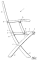
- shows a side view of a chair constructed in accordance with the invention in a folded-out position,
- Fig. 2
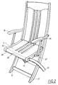
- shows a perspective view of the chair of Fig. 1,
- Fig. 3
- and Fig. 4 show a side view of the chair of Fig. 1 in an intermediate folded position and a final folded position respectively.
- Fig.1 shows an article of
furniture 1 which, in the preferred embodiment, is a chair. The chair is generally symmetrical about a plane passing through the middle of the seat, i.e. midway between the twoarmrests 34 and 36 (see Fig.2), although the provision of no armrests, only one armrest or more than two armrests is possible. - The chair has a
support surface 2 which is formed by two relatively rigid sections, afirst section 3 and a second section 5 (see Fig.3). Thesesections pivot pin 14, located approximately mid-way between thepivots pivots sections - The support leg means 10 and 12 are joined to one another at a
pivot location 6 positioned approximately equidistantly from the base of each of the leg means 10 and 12 respectively. - As can be seen more clearly in Fig.2 and Fig.3, the
first section 3 is formed as a substantially U-shaped frame (as seen from above) which has twoarms second section 5. The arm 30 is connected toarm 32 proximate the front edge of the chair by across member 26. - The
first section 3 has twofree ends 7 which are supported on thebackrest 20 of the chair by means of across brace 16 spanning the twoleg portion 12, 12' of the support leg means 12. - At the front edge of the chair the first section and the second section are each provided with cooperating portions 3a and 5a respectively. In the folded-out position as shown in Fig.1, the portion 5a overlies and is supported on the portion 3a (normally formed on member 26), as shown in hidden detail lines in Fig.1. This provides a very stable and secure construction for the chair since any load applied to the
surface 2 is taken bysections cross brace 16 as well as thesection 5 being supported by the front edge arrangement of 3a and 5a. With such an arrangement thecentral pivot 14 will thus be in a relatively unloaded condition. - The
cross member 26 may also be provided with a cut-away portion 28 to allow easy access to the front lip of thesection 5, in order that a user may easily grip the front lip for folding away the chair. - In the embodiment illustrated, the
member 26 lies behind the front lip of the second section 5 (see e.g. Fig.1). However themember 26 may itself form the front lip of the support surface. If desired, in this case, easier access can be gained to the second section 5 (for folding away) by the provision of a cut away portion (not shown), similar to theshape 28, allowing insertion of a hand between themember 26 and thesecond section 5. - The chair may be provided with an
arm rest portion locations pivot 14 may serve as the pivot location not only for connecting the twosections - Precise details of the pivot connections are not shown in the figures, but it will be clear to the skilled person that the pivots may be of any suitable type. For example the
pivot 24 need not be a pin connection but could be a hinge type for instance. Similarly thepivot 8 may extend as one pin through the wholesecond section 5, but may be formed as two separate pin sections extending from either side to whatever distance is appropriate. - In order to fold the seat away from its folded-out position in Fig.1 and Fig.2, the user may take hold of the front edge of the
second section 5, e.g. on the part 5a, and lift upwardly whilst preventing the leg means 10 from moving backwardly. Continued upward movement of thesection 5 will thus collapse the chair fully into the position shown in Fig.4. Folding-out again is merely a matter of moving thesecond section 5 downwardly. - Folding away of the chair may also be accomplished by lifting one of the
members 30, 32 of the first section and moving this upwardly. When no armrest is provided it will be clear that no obstacle prevents continuous upward movement from the sides of the chair and similarly when only one armrest is provided, access will be easiest from the side with no armrest. - Whilst it is not essential, the comfort of the chair can be enhanced by arranging the height of the
sections sections seat 2 are substantially at the same level. This can be achieved by appropriate location of thepivot point 14 with respect to the chosen material depth of each of thesections pivot location 14. - The resultant chair is thus stable, easily manageable even when heavy (e.g. large wooden chairs) and obviates the use of sliding hinges, sliding pivots or fastening means such as hooks.
- Whilst the invention has been described with reference to the embodiment shown in the drawings, it will be appreciated by those skilled in the art that many variations are possible within the scope of the invention as defined by the appended claims. For example, whilst the invention has been explained with reference to a chair, other articles of furniture are also encompassed by the invention such as foldable tables, stools, benches and the like which provide a support surface for articles or people.
Claims (10)
- Foldable article (1) of furniture, foldable between a collapsed position and a folded-out position, said article being provided with an upwardly-facing support surface (2), upon which surface (2) objects can be placed directly from above in said folded-out position, said surface (2) being pivotally connected to underlying support leg means (10, 12), wherein said surface (2) comprises an upwardly-facing first section (3) for supporting objects placed thereon directly from above, characterized in that, in said folded-out position, said upwardly-facing support surface (2) is constituted by both said first section (3) and a second section (5), in which said second section (5) is also an upwardly-facing support surface for supporting objects placed thereon directly from above, and in that each of said support-surface sections (3, 5) is pivotally connected to a respective one of said support leg means (10, 12) and to each other.
- Foldable article according to claim 1, characterized in that the first and second sections (3, 5) are pivotally connected to each other at a location (14) remote from their respective ends.
- Foldable article according to either of claims 1 or 2, characterized in that there are two underlying support leg means (10, 12) connected to each other at a pivot location (6).
- Foldable article according to any one of the preceding claims, characterized in that in that a portion (5a) of said second section (5) overlies and is supported on a portion (3a) of said first section (3) in the folded-out position of the article.
- Foldable article according to any one of the preceding claims, characterized in that, in the folded-out position, the upper surface of the first section (3) and the upper surface of the second section (5) are at substantially the same level.
- Foldable article according to any one of the preceding claims, characterized in that said first section, in plan view, comprises a substantially U-shaped outer frame.
- Foldable article according to any one of the preceding claims, characterized in that the foldable article has a backrest (20) and in that the support surface (2) forms a seat portion, said overlying portions (3a, 5a) of said first and second sections being positioned at the edge remote from the backrest, and in that said first and second sections (3, 5) forming said support surface (2) are attached to said leg means (10, 12) at respective first and second spaced pivot locations (4, 8).
- Foldable article according to any one of the preceding claims, characterized in that all pivot locations (4, 6, 8, 10, 14, 22, 24) on the article are substantially fixed with respect to said article, so that no sliding pivot locations or joints are provided.
- Foldable article according to any one of the preceding claims, characterized in that a cross brace (16) is provided at a location such that it provides support for the first and the second sections (3a, 5a) in the folded-out position.
- Foldable article according to any one of claims 5 to 9, characterized in that the member (26) of the U-shaped frame which joins together the two free arms (30, 32) of the U-shaped member is provided with a recessed portion (28) to give easy access to the front edge of the second section (5).
Priority Applications (3)
| Application Number | Priority Date | Filing Date | Title |
|---|---|---|---|
| DE1993616002 DE69316002T2 (en) | 1993-08-25 | 1993-08-25 | Folding chair |
| EP93850165A EP0640304B1 (en) | 1993-08-25 | 1993-08-25 | Folding furniture |
| US08/407,759 US5542739A (en) | 1993-08-25 | 1995-03-21 | Folding furniture |
Applications Claiming Priority (2)
| Application Number | Priority Date | Filing Date | Title |
|---|---|---|---|
| EP93850165A EP0640304B1 (en) | 1993-08-25 | 1993-08-25 | Folding furniture |
| US08/407,759 US5542739A (en) | 1993-08-25 | 1995-03-21 | Folding furniture |
Publications (2)
| Publication Number | Publication Date |
|---|---|
| EP0640304A1 EP0640304A1 (en) | 1995-03-01 |
| EP0640304B1 true EP0640304B1 (en) | 1997-12-29 |
Family
ID=26134934
Family Applications (1)
| Application Number | Title | Priority Date | Filing Date |
|---|---|---|---|
| EP93850165A Expired - Lifetime EP0640304B1 (en) | 1993-08-25 | 1993-08-25 | Folding furniture |
Country Status (2)
| Country | Link |
|---|---|
| US (1) | US5542739A (en) |
| EP (1) | EP0640304B1 (en) |
Families Citing this family (6)
| Publication number | Priority date | Publication date | Assignee | Title |
|---|---|---|---|---|
| US7066534B2 (en) | 2001-08-10 | 2006-06-27 | North Pole Limited | Hard arm chair with sliding arm mechanisms |
| US6682138B2 (en) * | 2002-03-29 | 2004-01-27 | Adams Mfg. Corp. | Resin molded folding chair |
| GB0306691D0 (en) * | 2003-03-22 | 2003-04-30 | Folding Company The Ltd | Folding linkage |
| CN2624728Y (en) * | 2003-04-21 | 2004-07-14 | 常州市侨裕集团有限公司 | Folding chair with soft armrests |
| WO2010051665A1 (en) * | 2008-11-07 | 2010-05-14 | Leng Luhao | Foldable chair |
| GB2572807B (en) * | 2018-04-12 | 2022-07-13 | Stannah Stairlifts Ltd | Improvements in or relating to folding chairs |
Family Cites Families (10)
| Publication number | Priority date | Publication date | Assignee | Title |
|---|---|---|---|---|
| FR621843A (en) * | 1926-09-21 | 1927-05-18 | Accumulation device particularly applicable to folding furniture of tabular shape | |
| DE510240C (en) * | 1929-05-03 | 1930-10-17 | Wilhelm Preuss Jr | Folding chair with legs crossing like scissors |
| US1989865A (en) * | 1932-09-23 | 1935-02-05 | Karl G Johanson | Folding chair |
| US1959046A (en) * | 1933-02-06 | 1934-05-15 | Jacob D Welliver | Folding chair |
| CH185102A (en) * | 1936-01-25 | 1936-07-15 | Urech Oswald | Collapsible chair. |
| US2741298A (en) * | 1953-03-02 | 1956-04-10 | Trans Trading Corp | Folding rocking chair |
| US2762057A (en) * | 1955-01-20 | 1956-09-11 | Root Jeanne | Sitz bath stool or chair |
| US3907359A (en) * | 1974-11-26 | 1975-09-23 | Cosby D Joiner | Foldable chair |
| DE8614186U1 (en) * | 1986-05-26 | 1986-07-17 | Drabert Söhne GmbH & Co, 4950 Minden | chair |
| IL92213A0 (en) * | 1989-11-05 | 1990-07-26 | Amiram Mann | Foldable chair |
-
1993
- 1993-08-25 EP EP93850165A patent/EP0640304B1/en not_active Expired - Lifetime
-
1995
- 1995-03-21 US US08/407,759 patent/US5542739A/en not_active Expired - Fee Related
Also Published As
| Publication number | Publication date |
|---|---|
| EP0640304A1 (en) | 1995-03-01 |
| US5542739A (en) | 1996-08-06 |
Similar Documents
| Publication | Publication Date | Title |
|---|---|---|
| US4826241A (en) | Folding chair | |
| US20010026086A1 (en) | Folding table and seating apparatus | |
| US4538308A (en) | Convertible furniture | |
| US2983308A (en) | Folding picnic table and benches | |
| US4591205A (en) | Glider recliner | |
| US5647632A (en) | Chair convertible to bench or settee | |
| US20070144831A1 (en) | Foldable chair and ladder combination | |
| US20130000529A1 (en) | Stabilisation of Objects | |
| US8141956B2 (en) | Chair foldable from a single sheet of planar material | |
| US10376062B2 (en) | Mobile folding restaurant booth style bench | |
| EP0640304B1 (en) | Folding furniture | |
| US5052703A (en) | Dolly | |
| WO2007099376A2 (en) | Folding articles | |
| MXPA04002051A (en) | Improvements in furniture combination bed and desk. | |
| GB2331233A (en) | A collapsible combined sun-bed and deck-chair | |
| US4976492A (en) | Foldable outdoor chair | |
| US9980583B2 (en) | Mobile folding restaurant booth style bench | |
| US4960303A (en) | Folding table and seat assembly | |
| US5588695A (en) | Foldable beach chair | |
| US4580834A (en) | Chair convertible to easy chair | |
| US6186591B1 (en) | Table with self-adjusting midframe support | |
| US4334710A (en) | Collapsible, portable dental chair | |
| US11350749B2 (en) | Modular chair | |
| GB2303058A (en) | Folding chair | |
| US2717630A (en) | Foldable reclining rocking chair |
Legal Events
| Date | Code | Title | Description |
|---|---|---|---|
| PUAI | Public reference made under article 153(3) epc to a published international application that has entered the european phase |
Free format text: ORIGINAL CODE: 0009012 |
|
| AK | Designated contracting states |
Kind code of ref document: A1 Designated state(s): DE DK ES FR GB IT NL SE |
|
| 17P | Request for examination filed |
Effective date: 19950731 |
|
| 17Q | First examination report despatched |
Effective date: 19960415 |
|
| GRAG | Despatch of communication of intention to grant |
Free format text: ORIGINAL CODE: EPIDOS AGRA |
|
| GRAG | Despatch of communication of intention to grant |
Free format text: ORIGINAL CODE: EPIDOS AGRA |
|
| GRAG | Despatch of communication of intention to grant |
Free format text: ORIGINAL CODE: EPIDOS AGRA |
|
| GRAH | Despatch of communication of intention to grant a patent |
Free format text: ORIGINAL CODE: EPIDOS IGRA |
|
| GRAH | Despatch of communication of intention to grant a patent |
Free format text: ORIGINAL CODE: EPIDOS IGRA |
|
| GRAA | (expected) grant |
Free format text: ORIGINAL CODE: 0009210 |
|
| AK | Designated contracting states |
Kind code of ref document: B1 Designated state(s): DE DK ES FR GB IT NL SE |
|
| PG25 | Lapsed in a contracting state [announced via postgrant information from national office to epo] |
Ref country code: IT Free format text: LAPSE BECAUSE OF FAILURE TO SUBMIT A TRANSLATION OF THE DESCRIPTION OR TO PAY THE FEE WITHIN THE PRE;WARNING: LAPSES OF ITALIAN PATENTS WITH EFFECTIVE DATE BEFORE 2007 MAY HAVE OCCURRED AT ANY TIME BEFORE 2007. THE CORRECT EFFECTIVE DATE MAY BE DIFFERENT FROM THE ONE RECORDED.SCRIBED TIME-LIMIT Effective date: 19971229 Ref country code: FR Free format text: LAPSE BECAUSE OF FAILURE TO SUBMIT A TRANSLATION OF THE DESCRIPTION OR TO PAY THE FEE WITHIN THE PRESCRIBED TIME-LIMIT Effective date: 19971229 Ref country code: ES Free format text: THE PATENT HAS BEEN ANNULLED BY A DECISION OF A NATIONAL AUTHORITY Effective date: 19971229 |
|
| REF | Corresponds to: |
Ref document number: 69316002 Country of ref document: DE Date of ref document: 19980205 |
|
| EN | Fr: translation not filed | ||
| PG25 | Lapsed in a contracting state [announced via postgrant information from national office to epo] |
Ref country code: GB Free format text: LAPSE BECAUSE OF NON-PAYMENT OF DUE FEES Effective date: 19980825 Ref country code: DK Free format text: LAPSE BECAUSE OF NON-PAYMENT OF DUE FEES Effective date: 19980825 |
|
| PG25 | Lapsed in a contracting state [announced via postgrant information from national office to epo] |
Ref country code: SE Free format text: LAPSE BECAUSE OF NON-PAYMENT OF DUE FEES Effective date: 19980826 |
|
| PLBE | No opposition filed within time limit |
Free format text: ORIGINAL CODE: 0009261 |
|
| STAA | Information on the status of an ep patent application or granted ep patent |
Free format text: STATUS: NO OPPOSITION FILED WITHIN TIME LIMIT |
|
| 26N | No opposition filed | ||
| PG25 | Lapsed in a contracting state [announced via postgrant information from national office to epo] |
Ref country code: NL Free format text: LAPSE BECAUSE OF NON-PAYMENT OF DUE FEES Effective date: 19990301 |
|
| GBPC | Gb: european patent ceased through non-payment of renewal fee |
Effective date: 19980825 |
|
| EUG | Se: european patent has lapsed |
Ref document number: 93850165.7 |
|
| NLV4 | Nl: lapsed or anulled due to non-payment of the annual fee |
Effective date: 19990301 |
|
| PG25 | Lapsed in a contracting state [announced via postgrant information from national office to epo] |
Ref country code: DE Free format text: LAPSE BECAUSE OF NON-PAYMENT OF DUE FEES Effective date: 19990601 |
|
| REG | Reference to a national code |
Ref country code: DK Ref legal event code: EBP |