EP0640042B1 - Method of forming an orifice array for a high density ink jet printhead - Google Patents
Method of forming an orifice array for a high density ink jet printhead Download PDFInfo
- Publication number
- EP0640042B1 EP0640042B1 EP93911077A EP93911077A EP0640042B1 EP 0640042 B1 EP0640042 B1 EP 0640042B1 EP 93911077 A EP93911077 A EP 93911077A EP 93911077 A EP93911077 A EP 93911077A EP 0640042 B1 EP0640042 B1 EP 0640042B1
- Authority
- EP
- European Patent Office
- Prior art keywords
- cover plate
- forming
- layer
- indentation
- aperture
- Prior art date
- Legal status (The legal status is an assumption and is not a legal conclusion. Google has not performed a legal analysis and makes no representation as to the accuracy of the status listed.)
- Expired - Lifetime
Links
Images

Classifications
-
- B—PERFORMING OPERATIONS; TRANSPORTING
- B41—PRINTING; LINING MACHINES; TYPEWRITERS; STAMPS
- B41J—TYPEWRITERS; SELECTIVE PRINTING MECHANISMS, i.e. MECHANISMS PRINTING OTHERWISE THAN FROM A FORME; CORRECTION OF TYPOGRAPHICAL ERRORS
- B41J2/00—Typewriters or selective printing mechanisms characterised by the printing or marking process for which they are designed
- B41J2/005—Typewriters or selective printing mechanisms characterised by the printing or marking process for which they are designed characterised by bringing liquid or particles selectively into contact with a printing material
- B41J2/01—Ink jet
- B41J2/135—Nozzles
- B41J2/16—Production of nozzles
- B41J2/1621—Manufacturing processes
- B41J2/1632—Manufacturing processes machining
- B41J2/1634—Manufacturing processes machining laser machining
-
- B—PERFORMING OPERATIONS; TRANSPORTING
- B23—MACHINE TOOLS; METAL-WORKING NOT OTHERWISE PROVIDED FOR
- B23K—SOLDERING OR UNSOLDERING; WELDING; CLADDING OR PLATING BY SOLDERING OR WELDING; CUTTING BY APPLYING HEAT LOCALLY, e.g. FLAME CUTTING; WORKING BY LASER BEAM
- B23K26/00—Working by laser beam, e.g. welding, cutting or boring
- B23K26/36—Removing material
- B23K26/38—Removing material by boring or cutting
- B23K26/382—Removing material by boring or cutting by boring
- B23K26/384—Removing material by boring or cutting by boring of specially shaped holes
-
- B—PERFORMING OPERATIONS; TRANSPORTING
- B41—PRINTING; LINING MACHINES; TYPEWRITERS; STAMPS
- B41J—TYPEWRITERS; SELECTIVE PRINTING MECHANISMS, i.e. MECHANISMS PRINTING OTHERWISE THAN FROM A FORME; CORRECTION OF TYPOGRAPHICAL ERRORS
- B41J2/00—Typewriters or selective printing mechanisms characterised by the printing or marking process for which they are designed
- B41J2/005—Typewriters or selective printing mechanisms characterised by the printing or marking process for which they are designed characterised by bringing liquid or particles selectively into contact with a printing material
- B41J2/01—Ink jet
- B41J2/135—Nozzles
- B41J2/16—Production of nozzles
- B41J2/162—Manufacturing of the nozzle plates
-
- B—PERFORMING OPERATIONS; TRANSPORTING
- B41—PRINTING; LINING MACHINES; TYPEWRITERS; STAMPS
- B41J—TYPEWRITERS; SELECTIVE PRINTING MECHANISMS, i.e. MECHANISMS PRINTING OTHERWISE THAN FROM A FORME; CORRECTION OF TYPOGRAPHICAL ERRORS
- B41J2/00—Typewriters or selective printing mechanisms characterised by the printing or marking process for which they are designed
- B41J2/005—Typewriters or selective printing mechanisms characterised by the printing or marking process for which they are designed characterised by bringing liquid or particles selectively into contact with a printing material
- B41J2/01—Ink jet
- B41J2/135—Nozzles
- B41J2/16—Production of nozzles
- B41J2/1621—Manufacturing processes
- B41J2/1623—Manufacturing processes bonding and adhesion
-
- Y—GENERAL TAGGING OF NEW TECHNOLOGICAL DEVELOPMENTS; GENERAL TAGGING OF CROSS-SECTIONAL TECHNOLOGIES SPANNING OVER SEVERAL SECTIONS OF THE IPC; TECHNICAL SUBJECTS COVERED BY FORMER USPC CROSS-REFERENCE ART COLLECTIONS [XRACs] AND DIGESTS
- Y10—TECHNICAL SUBJECTS COVERED BY FORMER USPC
- Y10T—TECHNICAL SUBJECTS COVERED BY FORMER US CLASSIFICATION
- Y10T29/00—Metal working
- Y10T29/49—Method of mechanical manufacture
- Y10T29/49401—Fluid pattern dispersing device making, e.g., ink jet
Definitions
- the invention relates to a method of forming an orifice array for a high density ink jet printhead and, more particularly, to a method of forming an orifice array for an ink jet printhead using a two-step laser ablation technique.
- ink jet printing A popular form of non-impact printing is generally referred to as ink jet printing.
- Ink jet printing systems use the ejection of tiny droplets of ink to produce an image.
- the devices produce highly reproducible and controllable droplets, so that a droplet may be printed at a location specified by digitally stored image data.
- Most ink jet printing systems commercially available may be generally classified as either a "continuous jet” type ink jet printing system where droplets are continuously ejected from the printhead and either directed to or away from the paper depending on the desired image to be produced or as a "drop on demand” type ink jet printing system where droplets are ejected from the printhead in response to a specific command related to the image to be produced.
- Continuous jet type ink jet printing systems are based upon the phenomena of uniform droplet formation from a stream of liquid issuing from an orifice. It had been previously observed that fluid ejected under pressure from an orifice about 50 to 80 microns in diameter tends to break up into uniform droplets upon the amplification of capillary waves induced onto the jet, for example, by an electromechanical device that causes pressure oscillations to propagate through the fluid. In this manner, ink is forced through the orifice where it forms a droplet. The droplet is electrostatically charged and then attracted towards an oppositely charged platen located behind a sheet of paper. Using electrically controlled deflection plates similar to those in a CRT, the trajectory of the droplet can be controlled to hit a desired spot on the paper.
- Most drop-on-demand type ink jet printheads include a body portion having a plurality of ink-carrying channels formed therein from which droplets of ink are ejected. Many of such ink jet printheads also include a cover plate fixedly mounted on the front end of the body portion. Extending through the cover plate would be a plurality of orifices which comprise the orifice array for the ink jet printhead. In most ink jet printheads, each orifice in the orifice array corresponds to one of the channels extending through the body portion. The cover plate is positioned on the front end of the body portion such that each orifice is in communication with the corresponding channel. When a pressure wave is created in a channel, the ink droplet is forcedly ejected from the ink jet printhead through the orifice in communication with that channel.
- an orifice array for an ink jet printhead it was common to take the unattached cover plate and to drill a series of orifices therethrough, for example, utilizing conventional laser drilling techniques. Once drilling of the orifices was completed, a coating of an adhesive material, for example, epoxy, was placed on the back surface of the cover and/or the front end of the main body of the ink jet printhead. The cover would then be aligned with the front end of the main body so that each orifice was located in front of and in communication with a corresponding channel extending through the main body of the ink jet printhead. After alignment of the cover plate and main body was completed, the cover would then be bonded to the front end of the main body of the ink jet printhead.
- an adhesive material for example, epoxy
- Still another problem in manufacturing ink jet printheads using conventional laser drilling techniques is the inability of such techniques to precisely control the shape and edge conditions of an orifice formed along the exit or ink-ejecting side of the cover plate.
- the cover plate Prior to ablating an orifice in a cover plate, the cover plate must first be fixedly mounted on a support surface. Most commonly, the support surface has a number of air-drawing apertures, also known as “vacuum chucks", formed therein. By positioning the cover plate over the apertures, the suction provided thereby fixedly supports the cover plate on the support structure.
- the laser will also partially ablate the support surface, thereby resulting in the release of gaseous byproducts.
- the present invention as disclosed in claim 1 shows a method of forming an orifice in a cover plate for an ink jet printhead.
- An indentation is formed in a cover plate having a removable backing, a front side layer formed from an ablatable inactive material, and an intermediate layer formed from an adhesive material. The indentation extends through the removable backing and the intermediate layer and partially through the front side layer, thereby exposing an interior surface of the front side layer. An aperture extending from a portion of the exposed interior surface and through the front side layer is then formed in the cover plate.
- the indentation may be formed in a generally rectangular shape, preferably a square approximately 80 ⁇ m along each side and, in another aspect, the aperture is formed in a generally circular shape, preferably 40 ⁇ m in diameter and positioned in the general center of the square indentation.
- the front side layer is formed of polyimide, a non-wettable material doped to absorb excimer radiation, or polyimide with a thin layer of a non-wettable material and, in yet another aspect of the invention, the indentation and aperture are formed by ablating the cover plate using excimer laser radiation.
- a support structure having a support surface formed from an ablatable material is provided and the cover plate is supported on the support surface before forming the aperture therein.
- the support structure may include a base support having an aperture of specified diameter formed therein. An aperture having a diameter less than the specified diameter is then formed in the support layer and the support layer positioned on the base support such that the apertures are in communication with each other. Air is then drawn through the base support aperture to secure the support layer on the base support. The cover plate is then positioned on the support layer such that air drawn through the support layer aperture secures the cover plate on the support layer.
- the indentation and aperture may then be formed in the cover plate at a location positioned above the ablatable material of the support layer.
- each indentation is formed in a generally rectangular shape, preferably a square 80 ⁇ m along a side, and, in another aspect of this embodiment of the invention, each aperture is formed in a generally circular shape, preferably in the general center of the corresponding indentation and having a diameter of approximately 40 ⁇ m.
- a method of forming an ink jet according to claim 18 wherein first a main body portion having a front end and at least one ink-carrying channel axially extending through the main body portion and in communication with the front end and a cover plate having front and back surfaces are provided. A corresponding number of ink-ejecting orifices, each having an indentation at the back surface, are then formed in the cover plate. The cover plate is then mounted to the main body portion such that each of the at least one ink-carrying channel is in communication with the corresponding ink-ejecting orifice. According to the invention, each orifice is formed by forming an indentation in the back surface of the cover plate to expose an interior surface.
- an aperture which extends from a portion of the exposed interior surface to the front surface of the cover plate is formed.
- a layer of adhesive is provided on the back side of the cover plate and a thermal bond between the layer of adhesive and the front end of the main body portion is formed to mount the cover plate to the main body portion. Excess adhesive produced during the formation of the thermal bond is collected by the indentation before the adhesive can flow into the orifice and clog it.
- a cover plate 10 for an ink jet printhead is comprised of a layer 12 of an ablatable inactive material, for example, polyimide or an ablatable non-wettable material doped to absorb excimer radiation, bonded to a layer of an adhesive material 14, for example, a thermal set adhesive such as an epoxy, which, in turn, is covered by a removable backing sheet 16.
- an ablatable inactive material for example, polyimide or an ablatable non-wettable material doped to absorb excimer radiation
- an adhesive material 14 for example, a thermal set adhesive such as an epoxy
- the cover plate 10 may be formed by properly dimensioning a commercially available sheet of material, for example, the type CMD901750 polyimide/adhesive laminated sheet manufactured by Rogers Corporation which consists of a 0.001 inch thick layer of Kapton polyimide, a 0.0006 inch thick layer of thermal-set adhesive and a 0.001 inch thick removable backing sheet. It should be noted, however, that other, differently configured cover plates are suitable for use herein. For example, it is contemplated that a similarly dimensioned sheet of a non-wettable material doped, for example, using a perfluoro aromatic compound, such that it will absorb excimer radiation would also be suitable for use herein. It is further contemplated that a properly dimensioned sheet of polyimide having a very thin surface layer of a non-wettable material between 0.1 and 5 microns thick formed thereon would be suitable for use in place of the layer 12.
- a commercially available sheet of material for example, the type CMD901750 polyimide/adhes
- the cover plate 10 is securably mounted to a support structure which includes a base support structure 23 and a support layer 20 of a highly ablatable material such as polyimide formed thereon.
- Vacuum means (not shown) draws air through air drawing apertures (or “vacuum chucks") 25 which extend through the base support structure and through corresponding apertures 21 which extend through the layer 20 and which are in communication with the apertures 25.
- a series of apertures 21 having diameters less than the diameters of the apertures 25 and positioned at locations corresponding to the locations of the apertures 25 of the base support structure 23 are formed in the support layer 20.
- a pair of apertures 25 and a corresponding pair of apertures 21 are provided on both sides of the locations where orifices are to be formed. It is contemplated, however, that various numbers of apertures 25 and corresponding apertures 21 would be suitable for use herein.
- the support layer 20 is then placed onto the top surface 23a of the base support structure 23 such that suction provided by air drawn through the apertures 25 secures the support layer 20 thereto.
- the layer 12 is then positioned on the top surface 20a of the support layer 20 such that air drawn through the apertures 21 holds the layer 12 in place.
- the UV radiation passes through a first mask 22 which, in the embodiment of the invention illustrated in FIGS. 1a-b is shown mounted to the end of the laser 18.
- the mask 22 modifies the UV radiation passing therethrough so that the radiation exiting therefrom, will ablate material forming the cover plate 10 in a desired shape at a series of spaced locations along a back side surface 17 of the cover plate 10.
- the mask 22 may be comprised of a thin sheet of metal having a series of apertures (not shown) formed in an array which patterns the desired shapes and locations of indentations to be formed at the site of each orifice of the orifice array to be formed.
- the mask 22 may be comprised of a sheet of glass having a thin film formed thereon which covers the entire sheet with the exception of particular locations which pattern the desired shapes and locations of the indentations.
- UV radiation emerges from the first mask 22 as a series of beams, each having a generally rectangular cross-section, and ablates material forming the cover plate 10 at the series of spaced locations to expose a generally rectangular interior surface 27 having selected dimensions of the layer 12 of inactive material, thereby forming indentations 26, each of which is formed at the site of an orifice, generally rectangular in shape and extends through the removable backing sheet 16, the layer 14 of adhesive material, part of the layer 12 of inactive material and terminates at the interior surface 27.
- the first mask 22 is removed and a second mask 24 is installed.
- the excimer laser 18 again generates UV radiation which now passes through the second mask 24.
- the second mask 24 directs the UV radiation to the same locations on the cover plate 10 but in beams having a generally circular, rather than rectangular, cross-section.
- the UV radiation striking the cover plate 10 at the specified locations pass through the indentations 26 and strike a portion of the interior surface 27 to ablate additional material which forms the layer 12 of inactive material, thereby providing a series of orifices 28, each having an indentation in communication therewith.
- Each of the orifices 28 has a generally circular cross-section having a diameter less than the length of the generally rectangular interior surface 27 and extending from the interior surface 27 to the front side surface 19 of the cover plate 10.
- the beams of UV radiation emerging from the second mask 24 are directed to strike in the general center of the generally rectangular interior surfaces 27 exposed in the first ablating step.
- the edges of the orifices formed by the beam will be smooth, rather than rough or jagged, as the emerging beams will immediately begin to ablate the highly ablatable material forming the support layer 20.
- the fully formed orifice includes an indentation 26, each indentation 26 having a generally rectangular cross-section and which extends from the back side surface 17 of the cover plate 10, through the backing sheet 16 and the adhesive layer 14 and partially through the polyimide layer 12, and an orifice 28 having a generally circular cross-section 28 which extends from the end of the indentation 26 to the front side surface 19 of the cover plate 10.
- the orifice 28 should have a diameter "a" of approximately 40 ⁇ m and the centers of adjacent orifices 28 should be approximately 173 ⁇ m apart.
- Each indentation 26 is preferably formed to have a generally square cross-section 80 ⁇ m ⁇ 5 ⁇ m along each side and separated from an adjacent indentation 26 by 90 ⁇ m ⁇ 5 ⁇ m.
- FIG. 4 a side view of a fully assembled ink jet printhead 29 having a main body portion 30 and a cover plate 10 formed in accordance with the methods described herein may now be seen.
- the main body portion 30 of the ink jet printhead 29 illustrated herein includes a lower body portion 32 having a plurality of axially extending grooves formed therein and blocked, at one end, by composite material 36, and an upper body portion 34, also having a plurality of axially extending grooves formed therein and blocked, at the one end, by composite material 38.
- the lower and upper body portions 32, 34 are mounted together to define a plurality of ink carrying channels 40 axially extending therethrough, each of which extends from a first end 42 located within the main body portion 30 and terminates at an opening along a front side 44 thereof.
- the ink carrying channels 40 should be generally parallel to each other along their entire length.
- Ink is supplied to the ink-carrying channels 40 by an ink supply means 42 via an external conduit 44.
- the external conduit 44 may deliver the ink to a vertically orientated internal conduit 46 which, in turn, supplies the ink to a manifold 48 extending lengthwise in the interior of the main body portion 30.
- a manifold 48 is in communication with each of the parallel ink-carrying channels 40, ink may be drawn from the manifold 48 and into the ink-carrying channels 40.
- a controller 50 which controls the actuation of the channels 40 is connected to the main body portion 30 by line 52.
- the present invention may be used in combination with those configurations of ink jet printheads where the main body portion 30 is formed of a single piece of material, either active or inactive, or formed of any number of components, again, either active or inactive, bonded together to form the main body portion 30. It is further contemplated that the present invention may be used to form a single orifice in an ink jet printhead having a single ink-carrying channel axially extending therethrough or an array of orifices in an ink jet printhead having multiple ink-carrying channels.
- the removable backing sheet 16 is peeled off of the cover plate 10, thereby exposing the layer 14 of adhesive material.
- the orifices 28 in the cover plate 10 are aligned with the corresponding ink carrying channels 40 of the main body portion 30 and the layer 14 of adhesive is then pressed, in the presence of heat, against the front side 44 of the main body portion 30 to thermally bond the cover plate 10 to the main body portion 30.
- Excess adhesive displaced from the layer 14 during the thermal bonding of the cover plate 10 to the main body portion 30 flows harmlessly into the indentations 26 instead of entering the orifices 28.
- the prior art problem of clogging of the orifices 28 or ink carrying channels 40 by excess adhesive material during the mounting process is avoided.
- each orifice 28 should be positioned such that it is located at the center of the end of the corresponding channel 40, thereby providing ink ejection nozzles for the channels 40. It is contemplated that the dimensions of the array of orifices 28 could be varied to cover various selected lengths along the cover plate 10, depending on the channel requirements of the particular ink jet printhead 29 envisioned. For example, the array of orifices 28 may extend about 0.193 inches along the cover plate 10 and be comprised of about twenty-eight orifices in a single row.
- an orifice or orifices in the cover plate 10 in accordance with the methods disclosed herein is that the taper of the orifices is reduced in comparison with traditional ablation techniques.
- conventional ablation techniques tend to form apertures which decrease in diameter as they extend through the material.
- orifices formed by such techniques are often characterized by a slight taper.
- the orifice 28 extends through only a portion of the layer 12 of ablatable material, the remainder of the layer 12 being used to form the indentation 26. By reducing the thickness of the portion of the layer 12 used to form the orifice, orifice taper is minimized.
Landscapes
- Engineering & Computer Science (AREA)
- Manufacturing & Machinery (AREA)
- Physics & Mathematics (AREA)
- Optics & Photonics (AREA)
- Plasma & Fusion (AREA)
- Mechanical Engineering (AREA)
- Particle Formation And Scattering Control In Inkjet Printers (AREA)
Abstract
Description
- The invention relates to a method of forming an orifice array for a high density ink jet printhead and, more particularly, to a method of forming an orifice array for an ink jet printhead using a two-step laser ablation technique.
- A popular form of non-impact printing is generally referred to as ink jet printing. Ink jet printing systems use the ejection of tiny droplets of ink to produce an image. The devices produce highly reproducible and controllable droplets, so that a droplet may be printed at a location specified by digitally stored image data. Most ink jet printing systems commercially available may be generally classified as either a "continuous jet" type ink jet printing system where droplets are continuously ejected from the printhead and either directed to or away from the paper depending on the desired image to be produced or as a "drop on demand" type ink jet printing system where droplets are ejected from the printhead in response to a specific command related to the image to be produced.
- Continuous jet type ink jet printing systems are based upon the phenomena of uniform droplet formation from a stream of liquid issuing from an orifice. It had been previously observed that fluid ejected under pressure from an orifice about 50 to 80 microns in diameter tends to break up into uniform droplets upon the amplification of capillary waves induced onto the jet, for example, by an electromechanical device that causes pressure oscillations to propagate through the fluid. In this manner, ink is forced through the orifice where it forms a droplet. The droplet is electrostatically charged and then attracted towards an oppositely charged platen located behind a sheet of paper. Using electrically controlled deflection plates similar to those in a CRT, the trajectory of the droplet can be controlled to hit a desired spot on the paper. Unused drops are deflected away from the paper into a reservoir for recycling of the ink. Due to the small size of the droplet and the precise trajectory control, ink jet printing quality can approach that of formed-character impact printing. One drawback to continuous jet type ink jet printing systems is that fluid must be jetting even when little or no printing is required. This requirement degrades the ink and decreases reliability of the printing system.
- Due to this drawback, there has been increased interest in the production of droplets by electromechanically induced pressure waves. In this type of system, a volumetric change in the fluid is induced by the application of a voltage pulse to a piezoelectric material which is directly or indirectly coupled to the fluid. This volumetric change causes pressure/velocity transients to occur in the fluid and these are directed so as to produce a droplet that issues from an orifice. Since the voltage is applied only when a droplet is desired, these types of ink jet printing systems are referred to as "drop-on-demand" type systems.
- Most drop-on-demand type ink jet printheads include a body portion having a plurality of ink-carrying channels formed therein from which droplets of ink are ejected. Many of such ink jet printheads also include a cover plate fixedly mounted on the front end of the body portion. Extending through the cover plate would be a plurality of orifices which comprise the orifice array for the ink jet printhead. In most ink jet printheads, each orifice in the orifice array corresponds to one of the channels extending through the body portion. The cover plate is positioned on the front end of the body portion such that each orifice is in communication with the corresponding channel. When a pressure wave is created in a channel, the ink droplet is forcedly ejected from the ink jet printhead through the orifice in communication with that channel.
- In order to form an orifice array for an ink jet printhead, it was common to take the unattached cover plate and to drill a series of orifices therethrough, for example, utilizing conventional laser drilling techniques. Once drilling of the orifices was completed, a coating of an adhesive material, for example, epoxy, was placed on the back surface of the cover and/or the front end of the main body of the ink jet printhead. The cover would then be aligned with the front end of the main body so that each orifice was located in front of and in communication with a corresponding channel extending through the main body of the ink jet printhead. After alignment of the cover plate and main body was completed, the cover would then be bonded to the front end of the main body of the ink jet printhead.
- A significant problem in manufacturing ink jet printheads in this manner was that the adhesive typically used to bond the back side of the cover plate to the front end of the main body of the ink jet printhead tends to clog or partially block the orifices formed in the cover plate. This problem has become of particular concern in view of the increasing popularity of higher density ink jet printheads, i.e. ink jet printheads having a channel array where adjacent channels are spaced between approximately four and eight mils apart. In such high density ink jet printheads, the likelihood that the cover plate could be mounted on the main body of the ink jet printhead without having the adhesive clogging or partially blocking at least one of the orifices formed in the cover plate has become increasingly more unlikely. This problem has significantly complicated present methods for manufacturing ink jet printheads.
- Another problem in manufacturing ink jet printheads using conventional laser drilling techniques is that, due to the convergence effects of an excimer laser beam, the width of orifices formed thereby tends to decrease as the laser extends deeper into the cover plate. As a result, orifices formed in this manner tend to taper from the entrance to exit sides of the cover plate. As a tapered orifice will affect the velocity and direction of a fluid passing therethrough, the velocity and direction of ink ejected by an ink jet printhead may be adversely affected by the taper of the orifice.
- Still another problem in manufacturing ink jet printheads using conventional laser drilling techniques is the inability of such techniques to precisely control the shape and edge conditions of an orifice formed along the exit or ink-ejecting side of the cover plate. Prior to ablating an orifice in a cover plate, the cover plate must first be fixedly mounted on a support surface. Most commonly, the support surface has a number of air-drawing apertures, also known as "vacuum chucks", formed therein. By positioning the cover plate over the apertures, the suction provided thereby fixedly supports the cover plate on the support structure. However, when the laser "punches" through the ink-ejecting side of the cover plate, the laser will also partially ablate the support surface, thereby resulting in the release of gaseous byproducts. Such byproducts tend to roughen the edges and alter the size and shape of the orifices being formed, thereby adversely affecting ink jet performance. This problem can be circumvented by locating the orifices over the apertures in the support surface. However, the resultant reduction in support during the ablation process can result in flaps of unablated material being left at the edges of an orifice. Like the aforementioned roughened edges, this too can adversely impact ink jet performance.
- The present invention as disclosed in claim 1 shows a method of forming an orifice in a cover plate for an ink jet printhead. An indentation is formed in a cover plate having a removable backing, a front side layer formed from an ablatable inactive material, and an intermediate layer formed from an adhesive material. The indentation extends through the removable backing and the intermediate layer and partially through the front side layer, thereby exposing an interior surface of the front side layer. An aperture extending from a portion of the exposed interior surface and through the front side layer is then formed in the cover plate. The indentation may be formed in a generally rectangular shape, preferably a square approximately 80 µm along each side and, in another aspect, the aperture is formed in a generally circular shape, preferably 40µm in diameter and positioned in the general center of the square indentation. In alternate aspects of the invention, the front side layer is formed of polyimide, a non-wettable material doped to absorb excimer radiation, or polyimide with a thin layer of a non-wettable material and, in yet another aspect of the invention, the indentation and aperture are formed by ablating the cover plate using excimer laser radiation.
- In one aspect of the invention, a support structure having a support surface formed from an ablatable material is provided and the cover plate is supported on the support surface before forming the aperture therein. The support structure may include a base support having an aperture of specified diameter formed therein. An aperture having a diameter less than the specified diameter is then formed in the support layer and the support layer positioned on the base support such that the apertures are in communication with each other. Air is then drawn through the base support aperture to secure the support layer on the base support. The cover plate is then positioned on the support layer such that air drawn through the support layer aperture secures the cover plate on the support layer. The indentation and aperture may then be formed in the cover plate at a location positioned above the ablatable material of the support layer.
- In another aspect of the present invention a method of forming an orifice array in a cover plate for an ink jet printhead is disclosed according to claim 13, wherein series of indentations are formed at spaced locations along a back surface of the cover plate to expose an interior surface of the cover plate. An aperture extending from the exposed interior surface to a front surface of the cover plate is then formed in each of the series of indentations. In one aspect of this embodiment, each indentation is formed in a generally rectangular shape, preferably a square 80 µm along a side, and, in another aspect of this embodiment of the invention, each aperture is formed in a generally circular shape, preferably in the general center of the corresponding indentation and having a diameter of approximately 40 µm.
- In yet another aspect of the present invention is disclosed a method of forming an ink jet according to
claim 18 wherein first a main body portion having a front end and at least one ink-carrying channel axially extending through the main body portion and in communication with the front end and a cover plate having front and back surfaces are provided. A corresponding number of ink-ejecting orifices, each having an indentation at the back surface, are then formed in the cover plate. The cover plate is then mounted to the main body portion such that each of the at least one ink-carrying channel is in communication with the corresponding ink-ejecting orifice. According to the invention, each orifice is formed by forming an indentation in the back surface of the cover plate to expose an interior surface. Then, an aperture which extends from a portion of the exposed interior surface to the front surface of the cover plate is formed. A layer of adhesive is provided on the back side of the cover plate and a thermal bond between the layer of adhesive and the front end of the main body portion is formed to mount the cover plate to the main body portion. Excess adhesive produced during the formation of the thermal bond is collected by the indentation before the adhesive can flow into the orifice and clog it. - The present invention may be better understood, and its numerous objects, features and advantages will become apparent to those skilled in the art by reference to the accompanying drawing, in which:
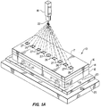
- FIG. 1a is a perspective view of a first ablating step used to form an orifice array constructed in accordance with the teachings of the present invention;
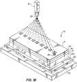
- FIG. 1b is a partially cut away perspective view of a second ablating step used to form an orifice array constructed in accordance with the teachings of the present invention;
- FIG. 2 is a cut away perspective view of a portion of a cover plate having an orifice array formed by the method illustrated in FIGS. 1a-b;
- FIG. 3 is a cross-sectional view of the cover plate of FIG. 2 taken along lines 3--3; and
- FIG. 4 is a side view of a fully assembled ink jet printhead constructed in accordance with the teachings of the present invention.
- Referring first to FIG. 1a, a method for forming an orifice array for an ink jet printhead in accordance with the teachings of the present invention shall now be described in greater detail. A
cover plate 10 for an ink jet printhead is comprised of alayer 12 of an ablatable inactive material, for example, polyimide or an ablatable non-wettable material doped to absorb excimer radiation, bonded to a layer of anadhesive material 14, for example, a thermal set adhesive such as an epoxy, which, in turn, is covered by aremovable backing sheet 16. Thecover plate 10 may be formed by properly dimensioning a commercially available sheet of material, for example, the type CMD901750 polyimide/adhesive laminated sheet manufactured by Rogers Corporation which consists of a 0.001 inch thick layer of Kapton polyimide, a 0.0006 inch thick layer of thermal-set adhesive and a 0.001 inch thick removable backing sheet. It should be noted, however, that other, differently configured cover plates are suitable for use herein. For example, it is contemplated that a similarly dimensioned sheet of a non-wettable material doped, for example, using a perfluoro aromatic compound, such that it will absorb excimer radiation would also be suitable for use herein. It is further contemplated that a properly dimensioned sheet of polyimide having a very thin surface layer of a non-wettable material between 0.1 and 5 microns thick formed thereon would be suitable for use in place of thelayer 12. - Before forming an orifice array in the
cover plate 10, thecover plate 10 is securably mounted to a support structure which includes abase support structure 23 and asupport layer 20 of a highly ablatable material such as polyimide formed thereon. Vacuum means (not shown) draws air through air drawing apertures (or "vacuum chucks") 25 which extend through the base support structure and throughcorresponding apertures 21 which extend through thelayer 20 and which are in communication with theapertures 25. To form the support structure, a series ofapertures 21 having diameters less than the diameters of theapertures 25 and positioned at locations corresponding to the locations of theapertures 25 of thebase support structure 23 are formed in thesupport layer 20. In the embodiment of the invention illustrated in FIGS. 1a-b, it is contemplated that a pair ofapertures 25 and a corresponding pair ofapertures 21 are provided on both sides of the locations where orifices are to be formed. It is contemplated, however, that various numbers ofapertures 25 andcorresponding apertures 21 would be suitable for use herein. Thesupport layer 20 is then placed onto thetop surface 23a of thebase support structure 23 such that suction provided by air drawn through theapertures 25 secures thesupport layer 20 thereto. Thelayer 12 is then positioned on the top surface 20a of thesupport layer 20 such that air drawn through theapertures 21 holds thelayer 12 in place. - In order to form an orifice array in the desired configuration, an
excimer laser 18 positioned above thecover plate 10 by mounting means (not shown), generates ultraviolet (or "UV") radiation capable of photoablating thecover plate 10. The UV radiation passes through afirst mask 22 which, in the embodiment of the invention illustrated in FIGS. 1a-b is shown mounted to the end of thelaser 18. Themask 22 modifies the UV radiation passing therethrough so that the radiation exiting therefrom, will ablate material forming thecover plate 10 in a desired shape at a series of spaced locations along aback side surface 17 of thecover plate 10. Themask 22 may be comprised of a thin sheet of metal having a series of apertures (not shown) formed in an array which patterns the desired shapes and locations of indentations to be formed at the site of each orifice of the orifice array to be formed. Alternately, themask 22 may be comprised of a sheet of glass having a thin film formed thereon which covers the entire sheet with the exception of particular locations which pattern the desired shapes and locations of the indentations. UV radiation emerges from thefirst mask 22 as a series of beams, each having a generally rectangular cross-section, and ablates material forming thecover plate 10 at the series of spaced locations to expose a generally rectangularinterior surface 27 having selected dimensions of thelayer 12 of inactive material, thereby formingindentations 26, each of which is formed at the site of an orifice, generally rectangular in shape and extends through theremovable backing sheet 16, thelayer 14 of adhesive material, part of thelayer 12 of inactive material and terminates at theinterior surface 27. - Referring next to FIG. 1b, after the
indentations 26 are formed in thecover plate 10, thefirst mask 22 is removed and a second mask 24 is installed. Theexcimer laser 18 again generates UV radiation which now passes through the second mask 24. The second mask 24 directs the UV radiation to the same locations on thecover plate 10 but in beams having a generally circular, rather than rectangular, cross-section. As a result, the UV radiation striking thecover plate 10 at the specified locations pass through theindentations 26 and strike a portion of theinterior surface 27 to ablate additional material which forms thelayer 12 of inactive material, thereby providing a series oforifices 28, each having an indentation in communication therewith. Each of theorifices 28 has a generally circular cross-section having a diameter less than the length of the generally rectangularinterior surface 27 and extending from theinterior surface 27 to thefront side surface 19 of thecover plate 10. Preferably, the beams of UV radiation emerging from the second mask 24 are directed to strike in the general center of the generally rectangularinterior surfaces 27 exposed in the first ablating step. As the beams ablate sufficient material such that they "punch" through thefront side surface 19 of thelayer 12, the edges of the orifices formed by the beam will be smooth, rather than rough or jagged, as the emerging beams will immediately begin to ablate the highly ablatable material forming thesupport layer 20. - Referring next to FIGS. 2 and 3, a fully formed orifice formed by the two step ablation technique described herein may now be seen. As previously noted, the fully formed orifice includes an
indentation 26, eachindentation 26 having a generally rectangular cross-section and which extends from theback side surface 17 of thecover plate 10, through thebacking sheet 16 and theadhesive layer 14 and partially through thepolyimide layer 12, and anorifice 28 having a generallycircular cross-section 28 which extends from the end of theindentation 26 to thefront side surface 19 of thecover plate 10. Preferably, theorifice 28 should have a diameter "a" of approximately 40 µm and the centers ofadjacent orifices 28 should be approximately 173 µm apart. Eachindentation 26 is preferably formed to have a generally square cross-section 80 µm ±5 µm along each side and separated from anadjacent indentation 26 by 90 µm ±5 µm. - Referring next to FIG. 4, a side view of a fully assembled
ink jet printhead 29 having amain body portion 30 and acover plate 10 formed in accordance with the methods described herein may now be seen. Themain body portion 30 of theink jet printhead 29 illustrated herein includes alower body portion 32 having a plurality of axially extending grooves formed therein and blocked, at one end, bycomposite material 36, and anupper body portion 34, also having a plurality of axially extending grooves formed therein and blocked, at the one end, bycomposite material 38. The lower andupper body portions ink carrying channels 40 axially extending therethrough, each of which extends from afirst end 42 located within themain body portion 30 and terminates at an opening along afront side 44 thereof. Preferably, theink carrying channels 40 should be generally parallel to each other along their entire length. - Ink is supplied to the ink-carrying
channels 40 by an ink supply means 42 via anexternal conduit 44. Many methods for supplying ink from the ink supply means to the ink-carrying channels are known in the art and, therefore, need not be described in greater detail here. For example, theexternal conduit 44 may deliver the ink to a vertically orientatedinternal conduit 46 which, in turn, supplies the ink to a manifold 48 extending lengthwise in the interior of themain body portion 30. As the manifold 48 is in communication with each of the parallel ink-carryingchannels 40, ink may be drawn from the manifold 48 and into the ink-carryingchannels 40. Acontroller 50 which controls the actuation of thechannels 40 is connected to themain body portion 30 byline 52. - Notwithstanding the specific configuration of the
ink jet printhead 29 described and illustrated herein, it should be fully understood that the methods described herein are readily applicable to numerous other ink jet printhead configurations. Specifically, it is contemplated that the present invention may be used in combination with those configurations of ink jet printheads where themain body portion 30 is formed of a single piece of material, either active or inactive, or formed of any number of components, again, either active or inactive, bonded together to form themain body portion 30. It is further contemplated that the present invention may be used to form a single orifice in an ink jet printhead having a single ink-carrying channel axially extending therethrough or an array of orifices in an ink jet printhead having multiple ink-carrying channels. - To mount the
cover plate 10 having an array oforifices 28 formed in accordance with the method described above, theremovable backing sheet 16 is peeled off of thecover plate 10, thereby exposing thelayer 14 of adhesive material. Theorifices 28 in thecover plate 10 are aligned with the correspondingink carrying channels 40 of themain body portion 30 and thelayer 14 of adhesive is then pressed, in the presence of heat, against thefront side 44 of themain body portion 30 to thermally bond thecover plate 10 to themain body portion 30. Excess adhesive displaced from thelayer 14 during the thermal bonding of thecover plate 10 to themain body portion 30 flows harmlessly into theindentations 26 instead of entering theorifices 28. Thus, by forming anindentation 26 at the site of eachorifice 28, the prior art problem of clogging of theorifices 28 orink carrying channels 40 by excess adhesive material during the mounting process is avoided. - Preferably, each
orifice 28 should be positioned such that it is located at the center of the end of the correspondingchannel 40, thereby providing ink ejection nozzles for thechannels 40. It is contemplated that the dimensions of the array oforifices 28 could be varied to cover various selected lengths along thecover plate 10, depending on the channel requirements of the particularink jet printhead 29 envisioned. For example, the array oforifices 28 may extend about 0.193 inches along thecover plate 10 and be comprised of about twenty-eight orifices in a single row. - Yet another benefit achieved by forming an orifice or orifices in the
cover plate 10 in accordance with the methods disclosed herein is that the taper of the orifices is reduced in comparison with traditional ablation techniques. As previously discussed, conventional ablation techniques tend to form apertures which decrease in diameter as they extend through the material. As a result, orifices formed by such techniques are often characterized by a slight taper. In the method of forming an orifice disclosed herein, theorifice 28 extends through only a portion of thelayer 12 of ablatable material, the remainder of thelayer 12 being used to form theindentation 26. By reducing the thickness of the portion of thelayer 12 used to form the orifice, orifice taper is minimized. - Thus, there has been described and illustrated herein a method for forming orifices in a cover plate for an ink jet printhead which minimizes the taper of the orifices formed thereby, reduces the likelihood that excess adhesive material will clog the orifices when the cover plate is mounted to a main body portion of the ink jet printhead, and prevents damage to the orifice edges during the ablation process. However, those skilled in the art will recognize that many modifications and variations besides those specifically mentioned may be made in the techniques described herein without departing from the subject-matter of the present invention as claimed.
Claims (19)
- A method of forming an orifice in a cover plate (10) for an ink jet printhead, comprising the steps of:
providing a cover plate (10) having a removable backing (16), a front side layer (12) formed from an ablatable inactive material, and an intermediate layer (14) formed from an adhesive material;
forming an indentation (26) in said cover plate, said indentation extending through said removable backing and said intermediate layer and partially through said front side layer, said indentation exposing an interior surface of said front side layer; and,
forming an aperture (28) in said cover plate, said aperture extending from a portion of said exposed interior surface of said front side layer therethrough. - A method according to claim 1, wherein said indentation (26) is formed in a generally rectangular shape.
- A method according to claim 2, wherein said aperture (28) is formed in a generally circular shape.
- A method according to claim 3, wherein said generally circular aperture is formed in the general center of said generally rectangular indentation.
- A method according to claim 4, wherein said generally circular aperture is formed having a diameter of approximately 40 µm and said generally rectangular indentation is a square approximately 80 µm along each side.
- A method according to claim 1, wherein the steps of forming an indentation and an aperture in said cover plate further comprises the step of ablating said cover plate using excimer laser radiation.
- A method according to claim 6, wherein said front side layer of said cover plate is formed of polyimide.
- A method according to claim 6 and further comprising the steps of: providing a support structure (23) having a support surface (20) formed from an ablatable material; and supporting said cover plate on said support surface of said support structure before forming said indentation in said cover plate.
- A method according to claim 8, wherein the step of providing a support structure having a support surface formed from an ablatable material further comprises the steps of: providing a base support (23) having an aperture (25) with a specified diameter formed therein; providing a support layer (20) formed from an ablatable material; forming at least one aperture (21) in said support layer having a diameter less than said specified diameter; positioning said support layer on said base support such that said apertures are in communication with one another; drawing air through said aperture to secure said support layer on said base support; and positioning said cover plate on said support layer such that air drawn through said support layer aperture secures said cover plate on said support layer.
- A method according to claim 9, wherein the steps of forming an indentation and aperture in said cover plate further comprises the steps of forming said indentation and aperture at a location positioned above said ablatable material of said support layer.
- A method according to claim 10, wherein said support layer is formed of polyimide.
- A method according to claim 1, wherein said front side layer of said cover plate is formed from a non-wettable material doped to absorb excimer radiation.
- A method according to any of claims 1 to 12, comprising the steps of:
forming a series of indentations at spaced locations in said cover plate to expose an interior surface of said cover plate; and,
forming an aperture in each of said series of indentations, each of said apertures extending from a portion of said exposed interior surface of said front side layer therethrough. - A method according to claim 13, wherein each of said indentations is formed in a generally rectangular shape.
- A method according to claim 14, wherein each of said apertures is formed in a generally circular shape.
- A method according to claim 15, wherein each of said generally circular apertures is formed in the general center of said corresponding generally rectangular indentation.
- A method according to claim 13, wherein the step of forming an orifice in said cover plate further comprises the step of ablating, using excimer laser radiation, said front side layer at each of said spaced locations.
- A method of forming an ink jet printhead, comprising the steps of:
providing a main body portion having a front end and at least one ink-carrying channel axially extending through said main body portion and in communication with said front end;
providing a cover plate having front and back surfaces;
forming, by a method according to any of claims 1 to 17, an ink-ejecting orifice in said cover plate for each of said at least one ink-carrying channels; and,
mounting said cover plate to said main body portion such that each of said at least one ink-carrying channel is in communication with said corresponding ink-ejecting orifice. - A method according to claim 18, further comprising the steps of: removing said removable backing; and, forming a thermal bond between said layer of adhesive material and said front end of said main body portion to mount said cover plate to said main body portion; said indentation collecting excess adhesive produced during said bonding step.
Applications Claiming Priority (3)
| Application Number | Priority Date | Filing Date | Title |
|---|---|---|---|
| US878463 | 1992-05-05 | ||
| US07/878,463 US5703631A (en) | 1992-05-05 | 1992-05-05 | Method of forming an orifice array for a high density ink jet printhead |
| PCT/US1993/004247 WO1993022141A1 (en) | 1992-05-05 | 1993-05-05 | Method of forming an orifice array for a high density ink jet printhead |
Publications (2)
| Publication Number | Publication Date |
|---|---|
| EP0640042A1 EP0640042A1 (en) | 1995-03-01 |
| EP0640042B1 true EP0640042B1 (en) | 1996-08-14 |
Family
ID=25372086
Family Applications (1)
| Application Number | Title | Priority Date | Filing Date |
|---|---|---|---|
| EP93911077A Expired - Lifetime EP0640042B1 (en) | 1992-05-05 | 1993-05-05 | Method of forming an orifice array for a high density ink jet printhead |
Country Status (7)
| Country | Link |
|---|---|
| US (1) | US5703631A (en) |
| EP (1) | EP0640042B1 (en) |
| AT (1) | ATE141218T1 (en) |
| AU (1) | AU4234593A (en) |
| CA (1) | CA2134341A1 (en) |
| DE (1) | DE69304050T2 (en) |
| WO (1) | WO1993022141A1 (en) |
Families Citing this family (22)
| Publication number | Priority date | Publication date | Assignee | Title |
|---|---|---|---|---|
| US6120131A (en) * | 1995-08-28 | 2000-09-19 | Lexmark International, Inc. | Method of forming an inkjet printhead nozzle structure |
| DE69625002T2 (en) * | 1995-08-28 | 2003-07-31 | Lexmark International Inc., Greenwich | Method of forming a nozzle structure for an ink jet printhead |
| US6183064B1 (en) | 1995-08-28 | 2001-02-06 | Lexmark International, Inc. | Method for singulating and attaching nozzle plates to printheads |
| TW342365B (en) * | 1995-12-21 | 1998-10-11 | Ricoh Microelectronics Kk | A printing mask with a plastic printing plate and process for producing the same |
| US6624382B2 (en) * | 1997-01-30 | 2003-09-23 | Anvik Corporation | Configured-hole high-speed drilling system for micro-via pattern formation, and resulting structure |
| US6188416B1 (en) | 1997-02-13 | 2001-02-13 | Microfab Technologies, Inc. | Orifice array for high density ink jet printhead |
| US6045214A (en) * | 1997-03-28 | 2000-04-04 | Lexmark International, Inc. | Ink jet printer nozzle plate having improved flow feature design and method of making nozzle plates |
| JP2957528B2 (en) * | 1997-10-07 | 1999-10-04 | 株式会社東京機械製作所 | Nozzle for inkjet printing, orifice member thereof, and method of manufacturing orifice member |
| US6668454B2 (en) * | 1997-12-10 | 2003-12-30 | Canon Kabushiki Kaisha | Method for manufacturing a liquid-discharging recording head |
| JP3880242B2 (en) * | 1998-05-20 | 2007-02-14 | キヤノン株式会社 | Through hole formation method |
| US6634734B1 (en) * | 1999-06-30 | 2003-10-21 | Canon Kabushiki Kaisha | Method for manufacturing ink jet recording head, ink jet recording head manufactured by such method, and laser working method |
| US6409308B1 (en) | 1999-11-19 | 2002-06-25 | Lexmark International, Inc. | Method of forming an inkjet printhead nozzle structure |
| US6555783B2 (en) * | 2000-02-03 | 2003-04-29 | Canon Kabushiki Kaisha | Laser processing method and laser processing apparatus |
| RU2174916C1 (en) * | 2000-03-14 | 2001-10-20 | Максимовский Сергей Николаевич | Printing plate for jet printing mechanisms |
| US6509546B1 (en) | 2000-03-15 | 2003-01-21 | International Business Machines Corporation | Laser excision of laminate chip carriers |
| US6648732B2 (en) | 2001-01-30 | 2003-11-18 | Hewlett-Packard Development Company, L.P. | Thin film coating of a slotted substrate and techniques for forming slotted substrates |
| US6627844B2 (en) * | 2001-11-30 | 2003-09-30 | Matsushita Electric Industrial Co., Ltd. | Method of laser milling |
| US20050036004A1 (en) * | 2003-08-13 | 2005-02-17 | Barbara Horn | Methods and systems for conditioning slotted substrates |
| US20050099451A1 (en) * | 2003-11-04 | 2005-05-12 | Videojet Technologies Inc. | Method and apparatus for reducing debris accumulation in an ink jet printhead |
| US7261477B2 (en) * | 2004-01-21 | 2007-08-28 | Silverbrook Research Pty Ltd | Method of on-demand printing |
| US8418523B2 (en) | 2008-03-03 | 2013-04-16 | Keith Lueck | Calibration and accuracy check system for a breath tester |
| JP2009233955A (en) * | 2008-03-26 | 2009-10-15 | Canon Inc | Method for manufacturing microstructural body and method for manufacturing liquid ejection head |
Family Cites Families (25)
| Publication number | Priority date | Publication date | Assignee | Title |
|---|---|---|---|---|
| US4157935A (en) * | 1977-12-23 | 1979-06-12 | International Business Machines Corporation | Method for producing nozzle arrays for ink jet printers |
| JPS56113470A (en) * | 1980-02-15 | 1981-09-07 | Ricoh Co Ltd | Manufacture of ink jet head |
| US4430784A (en) * | 1980-02-22 | 1984-02-14 | Celanese Corporation | Manufacturing process for orifice nozzle devices for ink jet printing apparati |
| JPS57182449A (en) * | 1981-05-07 | 1982-11-10 | Fuji Xerox Co Ltd | Forming method of ink jet multinozzle |
| JPS5863466A (en) * | 1981-10-13 | 1983-04-15 | Canon Inc | Manufacture of liquid jet recording head |
| JPS6054858A (en) * | 1983-09-02 | 1985-03-29 | Tanaka Kikinzoku Kogyo Kk | Ink jet nozzle for printer |
| JPS60125674A (en) * | 1983-12-13 | 1985-07-04 | Ricoh Co Ltd | Inkjet nozzle formation method |
| FR2557732B1 (en) * | 1983-12-28 | 1986-04-11 | Lefevre Rene | METHOD FOR PRODUCING MINIATURE PIEZOELECTRIC DEVICES USING LASER MACHINING AND DEVICES OBTAINED BY THIS PROCESS |
| JPS6194767A (en) * | 1984-10-15 | 1986-05-13 | Ricoh Co Ltd | Inkjet head and its manufacturing method |
| US4716423A (en) * | 1985-11-22 | 1987-12-29 | Hewlett-Packard Company | Barrier layer and orifice plate for thermal ink jet print head assembly and method of manufacture |
| JPS62124955A (en) * | 1985-11-26 | 1987-06-06 | Ricoh Co Ltd | Method for joining parts with micro holes |
| US4680859A (en) * | 1985-12-06 | 1987-07-21 | Hewlett-Packard Company | Thermal ink jet print head method of manufacture |
| US4922265A (en) * | 1986-04-28 | 1990-05-01 | Hewlett-Packard Company | Ink jet printhead with self-aligned orifice plate and method of manufacture |
| US4658269A (en) * | 1986-06-02 | 1987-04-14 | Xerox Corporation | Ink jet printer with integral electrohydrodynamic electrodes and nozzle plate |
| US4789425A (en) * | 1987-08-06 | 1988-12-06 | Xerox Corporation | Thermal ink jet printhead fabricating process |
| GB8722085D0 (en) * | 1987-09-19 | 1987-10-28 | Cambridge Consultants | Ink jet nozzle manufacture |
| US4932112A (en) * | 1988-10-06 | 1990-06-12 | Tim Tikkanen | Sieve plate and process for making it |
| ES2207908T3 (en) * | 1988-10-31 | 2004-06-01 | Canon Kabushiki Kaisha | HEAD FOR INK JETS AND METHOD FOR THE MANUFACTURING OF THE SAME, PLATE WITH DOWNLOAD OVERS FOR THE HEAD AND ITS METHOD OF MANUFACTURING AND APPARATUS FOR INK JETS WITH HEAD FOR INK JETS. |
| EP0372521B1 (en) * | 1988-12-07 | 1993-04-14 | Seiko Epson Corporation | On-demand type ink jet print head |
| DE3934587C2 (en) * | 1989-10-17 | 1998-11-19 | Bosch Gmbh Robert | Process for producing high-precision through holes in workpieces generated by laser radiation |
| US5016024A (en) * | 1990-01-09 | 1991-05-14 | Hewlett-Packard Company | Integral ink jet print head |
| JP2657957B2 (en) * | 1990-04-27 | 1997-09-30 | キヤノン株式会社 | Projection device and light irradiation method |
| JPH0422644A (en) * | 1990-05-18 | 1992-01-27 | Seiko Epson Corp | inkjet recording device |
| US5229785A (en) * | 1990-11-08 | 1993-07-20 | Hewlett-Packard Company | Method of manufacture of a thermal inkjet thin film printhead having a plastic orifice plate |
| US5208980A (en) * | 1991-12-31 | 1993-05-11 | Compag Computer Corporation | Method of forming tapered orifice arrays in fully assembled ink jet printheads |
-
1992
- 1992-05-05 US US07/878,463 patent/US5703631A/en not_active Expired - Lifetime
-
1993
- 1993-05-05 AU AU42345/93A patent/AU4234593A/en not_active Abandoned
- 1993-05-05 DE DE69304050T patent/DE69304050T2/en not_active Expired - Lifetime
- 1993-05-05 AT AT93911077T patent/ATE141218T1/en not_active IP Right Cessation
- 1993-05-05 EP EP93911077A patent/EP0640042B1/en not_active Expired - Lifetime
- 1993-05-05 CA CA002134341A patent/CA2134341A1/en not_active Abandoned
- 1993-05-05 WO PCT/US1993/004247 patent/WO1993022141A1/en not_active Ceased
Also Published As
| Publication number | Publication date |
|---|---|
| AU4234593A (en) | 1993-11-29 |
| US5703631A (en) | 1997-12-30 |
| DE69304050T2 (en) | 1997-02-20 |
| CA2134341A1 (en) | 1993-11-11 |
| ATE141218T1 (en) | 1996-08-15 |
| DE69304050D1 (en) | 1996-09-19 |
| EP0640042A1 (en) | 1995-03-01 |
| WO1993022141A1 (en) | 1993-11-11 |
Similar Documents
| Publication | Publication Date | Title |
|---|---|---|
| US5703631A (en) | Method of forming an orifice array for a high density ink jet printhead | |
| EP0619781B1 (en) | Method of forming tapered orifice arrays in fully assembled ink jet printheads | |
| CA2084390C (en) | Laser ablated nozzle member for inkjet printhead | |
| EP0471157B1 (en) | Photo-ablated components for inkjet printhead | |
| EP0564120B1 (en) | Nozzle member including ink flow channels | |
| US5442384A (en) | Integrated nozzle member and tab circuit for inkjet printhead | |
| US5635966A (en) | Edge feed ink delivery thermal inkjet printhead structure and method of fabrication | |
| US5684519A (en) | Ink jet head with buckling structure body | |
| JPH11129482A (en) | Method of manufacturing ink jet print head and filter element | |
| CA1334068C (en) | Manufacture of nozzles for ink jet printers | |
| US5818478A (en) | Ink jet nozzle placement correction | |
| EP0564069A2 (en) | Improved ink delivery system for an inkjet printhead | |
| US20010043252A1 (en) | Control of adhesive flow in an inkjet printer printhead | |
| US6209203B1 (en) | Method for making nozzle array for printhead | |
| JP2957528B2 (en) | Nozzle for inkjet printing, orifice member thereof, and method of manufacturing orifice member | |
| CA2084554C (en) | Integrated nozzle member and tab circuit for inkjet printhead | |
| EP0743184A2 (en) | Composite nozzle plate | |
| JP2002096472A (en) | Method of manufacturing nozzle substrate for inkjet head | |
| JPS60206656A (en) | Manufacturing of recording head | |
| JP2000198206A (en) | Nozzle-flow channel plate of inkjet head and method of manufacturing the same |
Legal Events
| Date | Code | Title | Description |
|---|---|---|---|
| PUAI | Public reference made under article 153(3) epc to a published international application that has entered the european phase |
Free format text: ORIGINAL CODE: 0009012 |
|
| 17P | Request for examination filed |
Effective date: 19941202 |
|
| AK | Designated contracting states |
Kind code of ref document: A1 Designated state(s): AT BE CH DE DK ES FR GB GR IE IT LI LU MC NL PT SE |
|
| 17Q | First examination report despatched |
Effective date: 19950801 |
|
| GRAH | Despatch of communication of intention to grant a patent |
Free format text: ORIGINAL CODE: EPIDOS IGRA |
|
| GRAA | (expected) grant |
Free format text: ORIGINAL CODE: 0009210 |
|
| AK | Designated contracting states |
Kind code of ref document: B1 Designated state(s): AT BE CH DE DK ES FR GB GR IE IT LI LU MC NL PT SE |
|
| PG25 | Lapsed in a contracting state [announced via postgrant information from national office to epo] |
Ref country code: NL Free format text: LAPSE BECAUSE OF FAILURE TO SUBMIT A TRANSLATION OF THE DESCRIPTION OR TO PAY THE FEE WITHIN THE PRESCRIBED TIME-LIMIT Effective date: 19960814 Ref country code: LI Effective date: 19960814 Ref country code: IT Free format text: LAPSE BECAUSE OF FAILURE TO SUBMIT A TRANSLATION OF THE DESCRIPTION OR TO PAY THE FEE WITHIN THE PRESCRIBED TIME-LIMIT;WARNING: LAPSES OF ITALIAN PATENTS WITH EFFECTIVE DATE BEFORE 2007 MAY HAVE OCCURRED AT ANY TIME BEFORE 2007. THE CORRECT EFFECTIVE DATE MAY BE DIFFERENT FROM THE ONE RECORDED. Effective date: 19960814 Ref country code: GR Free format text: LAPSE BECAUSE OF FAILURE TO SUBMIT A TRANSLATION OF THE DESCRIPTION OR TO PAY THE FEE WITHIN THE PRESCRIBED TIME-LIMIT Effective date: 19960814 Ref country code: ES Free format text: THE PATENT HAS BEEN ANNULLED BY A DECISION OF A NATIONAL AUTHORITY Effective date: 19960814 Ref country code: DK Effective date: 19960814 Ref country code: CH Effective date: 19960814 Ref country code: BE Effective date: 19960814 Ref country code: AT Effective date: 19960814 |
|
| REF | Corresponds to: |
Ref document number: 141218 Country of ref document: AT Date of ref document: 19960815 Kind code of ref document: T |
|
| REG | Reference to a national code |
Ref country code: IE Ref legal event code: FG4D Free format text: 69444 |
|
| REF | Corresponds to: |
Ref document number: 69304050 Country of ref document: DE Date of ref document: 19960919 |
|
| ET | Fr: translation filed | ||
| ET | Fr: translation filed | ||
| PG25 | Lapsed in a contracting state [announced via postgrant information from national office to epo] |
Ref country code: SE Effective date: 19961114 Ref country code: PT Effective date: 19961114 |
|
| NLV1 | Nl: lapsed or annulled due to failure to fulfill the requirements of art. 29p and 29m of the patents act | ||
| REG | Reference to a national code |
Ref country code: CH Ref legal event code: PL |
|
| PG25 | Lapsed in a contracting state [announced via postgrant information from national office to epo] |
Ref country code: IE Free format text: LAPSE BECAUSE OF NON-PAYMENT OF DUE FEES Effective date: 19970505 |
|
| PG25 | Lapsed in a contracting state [announced via postgrant information from national office to epo] |
Ref country code: LU Free format text: LAPSE BECAUSE OF NON-PAYMENT OF DUE FEES Effective date: 19970531 |
|
| PLBE | No opposition filed within time limit |
Free format text: ORIGINAL CODE: 0009261 |
|
| STAA | Information on the status of an ep patent application or granted ep patent |
Free format text: STATUS: NO OPPOSITION FILED WITHIN TIME LIMIT |
|
| 26N | No opposition filed | ||
| PG25 | Lapsed in a contracting state [announced via postgrant information from national office to epo] |
Ref country code: MC Effective date: 19971130 |
|
| REG | Reference to a national code |
Ref country code: GB Ref legal event code: IF02 |
|
| PGFP | Annual fee paid to national office [announced via postgrant information from national office to epo] |
Ref country code: FR Payment date: 20100601 Year of fee payment: 18 |
|
| PGFP | Annual fee paid to national office [announced via postgrant information from national office to epo] |
Ref country code: DE Payment date: 20100527 Year of fee payment: 18 |
|
| PGFP | Annual fee paid to national office [announced via postgrant information from national office to epo] |
Ref country code: GB Payment date: 20100401 Year of fee payment: 18 |
|
| REG | Reference to a national code |
Ref country code: DE Ref legal event code: R119 Ref document number: 69304050 Country of ref document: DE |
|
| REG | Reference to a national code |
Ref country code: DE Ref legal event code: R119 Ref document number: 69304050 Country of ref document: DE |
|
| GBPC | Gb: european patent ceased through non-payment of renewal fee |
Effective date: 20110505 |
|
| REG | Reference to a national code |
Ref country code: FR Ref legal event code: ST Effective date: 20120131 |
|
| PG25 | Lapsed in a contracting state [announced via postgrant information from national office to epo] |
Ref country code: FR Free format text: LAPSE BECAUSE OF NON-PAYMENT OF DUE FEES Effective date: 20110531 |
|
| REG | Reference to a national code |
Ref country code: DE Ref legal event code: R082 Ref document number: 69304050 Country of ref document: DE Representative=s name: BOEHMERT & BOEHMERT ANWALTSPARTNERSCHAFT MBB -, DE Effective date: 20120329 Ref country code: DE Ref legal event code: R081 Ref document number: 69304050 Country of ref document: DE Owner name: HEWLETT-PACKARD DEVELOPMENT COMPANY, L.P., HOU, US Free format text: FORMER OWNER: COMPAQ COMPUTER CORP., HOUSTON, TEX., US Effective date: 20120329 |
|
| PG25 | Lapsed in a contracting state [announced via postgrant information from national office to epo] |
Ref country code: GB Free format text: LAPSE BECAUSE OF NON-PAYMENT OF DUE FEES Effective date: 20110505 |
|
| PG25 | Lapsed in a contracting state [announced via postgrant information from national office to epo] |
Ref country code: DE Free format text: LAPSE BECAUSE OF NON-PAYMENT OF DUE FEES Effective date: 20111130 |