EP0639808A1 - Method for debugging sequence program - Google Patents
Method for debugging sequence program Download PDFInfo
- Publication number
- EP0639808A1 EP0639808A1 EP94907670A EP94907670A EP0639808A1 EP 0639808 A1 EP0639808 A1 EP 0639808A1 EP 94907670 A EP94907670 A EP 94907670A EP 94907670 A EP94907670 A EP 94907670A EP 0639808 A1 EP0639808 A1 EP 0639808A1
- Authority
- EP
- European Patent Office
- Prior art keywords
- steps
- sequence program
- data
- executed
- execution
- Prior art date
- Legal status (The legal status is an assumption and is not a legal conclusion. Google has not performed a legal analysis and makes no representation as to the accuracy of the status listed.)
- Granted
Links
Images


Classifications
-
- G—PHYSICS
- G06—COMPUTING OR CALCULATING; COUNTING
- G06F—ELECTRIC DIGITAL DATA PROCESSING
- G06F11/00—Error detection; Error correction; Monitoring
- G06F11/30—Monitoring
- G06F11/32—Monitoring with visual or acoustical indication of the functioning of the machine
- G06F11/323—Visualisation of programs or trace data
-
- G—PHYSICS
- G05—CONTROLLING; REGULATING
- G05B—CONTROL OR REGULATING SYSTEMS IN GENERAL; FUNCTIONAL ELEMENTS OF SUCH SYSTEMS; MONITORING OR TESTING ARRANGEMENTS FOR SUCH SYSTEMS OR ELEMENTS
- G05B19/00—Program-control systems
- G05B19/02—Program-control systems electric
- G05B19/04—Program control other than numerical control, i.e. in sequence controllers or logic controllers
- G05B19/042—Program control other than numerical control, i.e. in sequence controllers or logic controllers using digital processors
- G05B19/0426—Programming the control sequence
-
- G—PHYSICS
- G06—COMPUTING OR CALCULATING; COUNTING
- G06F—ELECTRIC DIGITAL DATA PROCESSING
- G06F2201/00—Indexing scheme relating to error detection, to error correction, and to monitoring
- G06F2201/865—Monitoring of software
Definitions
- a parallel branch section 52 following the execution of the step ST08 the steps ST09, ST10, ST11 are executed at the same time the execution of the step ST08 ends. Since these steps ST09, ST10, ST11 and the next steps ST12, ST13, ST14 have different execution times, the respective routes end at different times. When this happens, one of the steps ST12, ST13, ST14 which ends at first waits for the other steps to end, and then control proceeds to a next step (end step 53 in FIG. 3) at the time the last one of the steps ST12, ST13, ST14 ends.
- An interface 17 receives data from a keyboard 32 of the CRT/MDI unit 30, and transfers the received data to the processor 11.
- Data for the PMC 20 can also be entered from the keyboard 32. Specifically, the data entered from the keyboard 32 for the PMC 20 are also transferred through the interface 17 and the common RAM 12 to the PMC 20.
- a programming device 40 is connected to an interface 18, so that a machining program generated by the programming device 40 is read in through the interface 18.
- a machining program edited in the computerized numerical control (CNC) apparatus 10 can be outputted to the programming device 40 through the interface 18.
- a parallel branch section 52 following the execution of the step ST08 the steps ST09, ST10, ST11 are executed at the same time that the execution of the step ST08 ends. Since these steps ST09, ST10, ST11 and the next steps ST12, ST13, ST14 have different execution times, the respective routes end at different times. When this happens, one of the steps ST12, ST13, ST14 which ends at first waits for the other steps to end, and then control proceeds to a next step (end step 53 in FIG. 3) at the time the last one of the steps ST12, ST13, ST14 ends.
- the sampling time intervals are preset using the keyboard 32 or the like.
- the sampling time intervals may be determined by the PMC 20 based on the entered data.
- the sequence program may be executed once, the execution time of the sequence program and the maximum number of simultaneously executable steps may be measured by the PMC 20, and the sampling time intervals may be determined by the PMC 20 based on the measured data.
Landscapes
- Engineering & Computer Science (AREA)
- Physics & Mathematics (AREA)
- General Physics & Mathematics (AREA)
- Theoretical Computer Science (AREA)
- Automation & Control Theory (AREA)
- Data Mining & Analysis (AREA)
- Quality & Reliability (AREA)
- General Engineering & Computer Science (AREA)
- Programmable Controllers (AREA)
- Testing And Monitoring For Control Systems (AREA)
Abstract
Description
- The present invention relates to a system for debugging a sequence program which is to be executed by a programmable controller (PC), and more particularly to a system for debugging a sequence program which is generated by flowcharting.
- Sequence programs to be executed by a PC may be expressed by logic descriptions, ladder diagrams, etc. Flowcharting is advantageous as it makes an overall flow of work easy to understand. A flowchart represents a sequential process step by step. One typical example of flowchart is a sequential function chart (SFC). However, a program representative of specific operation in each step is expressed by logic descriptions, ladder diagrams, etc.
- FIG. 3 of the accompanying drawings shows a specific example of a sequence program which is generated according to flowcharting. The sequence program shown in FIG. 3 is composed of a total of 14 steps ST01 ∼ ST14 following an initial step ST00. In a
selective branch section 51 following the execution of the step ST01, either one of the steps ST02, ST03, ST04 is selected depending on the executed result of the step ST01. For example, if the step ST04 is selected and executed, then the step ST07 is executed, after which control is transferred to the step ST08. - In a
parallel branch section 52 following the execution of the step ST08, the steps ST09, ST10, ST11 are executed at the same time the execution of the step ST08 ends. Since these steps ST09, ST10, ST11 and the next steps ST12, ST13, ST14 have different execution times, the respective routes end at different times. When this happens, one of the steps ST12, ST13, ST14 which ends at first waits for the other steps to end, and then control proceeds to a next step (end step 53 in FIG. 3) at the time the last one of the steps ST12, ST13, ST14 ends. - One major process of debugging a generated sequence program is to reproduce varying states of signals which are traced during the execution of the program, at a low speed on a screen.
- Sequence programs generated by flowcharting have many program execution routes if the number of steps and branch instructions are increased. As those many program execution routes are difficult to confirm visually, those sequence programs cannot easily be debugged. If the programmer wishes to know which one of the steps is selected and executed in the
selective branch section 51 in FIG. 3 or which one of the steps ST12, ST13, ST14 is the slowest and how long the waiting step has been waiting in a waiting process involving the steps ST12, ST13, ST14, then it has been necessary to determine the execution times of the respective steps and employ a complex technique in a process of displaying tracing and debugging events. - It is therefore an object of the present invention to provide a system for debugging a sequence program generated by flowcharting while allowing a chronological flow of the steps of the sequence program to be easily confirmed.
- To achieve the above object, there is provided in accordance with the present invention a system for debugging a sequence program generated by flowcharting, comprising program executing means for executing the sequence program, sampling means for sampling steps being executed at predetermined time intervals while the sequence program is being executed, step storage means for storing the sampled steps, and display means for displaying data of the stored steps in a time series.
- While the sequence program is being executed by the program executing means, steps of the sequence program which are being executed are sampled at predetermined time intervals by the sampling means, and the sampled steps are stored in the step storage means. The stored data are displayed in a time series by the display means.
- Since the execution states of the steps are displayed at the predetermined time intervals, the operator can confirm at a glance a chronological flow of executed steps, and hence can simply confirm the execution speeds of certain steps and the simultaneous execution of a plurality of parallel steps.
-
- FIG. 1 is a diagram showing an example of displayed debugged data;
- FIG. 2 is a block diagram of the hardware arrangement of a computerized numerical control (CNC) apparatus for carrying out the present invention;
- FIG. 3 is a diagram showing a specific example of sequence program generated by flowcharting; and
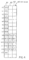
- FIG. 4 is a diagram showing an example of debugged data produced when a sequence program is sampled.
- FIG. 2 shows in block form the hardware arrangement of a computerized numerical control (CNC) apparatus for carrying out the present invention. In FIG. 2, a programmable machine controller (PMC) 20 is one type of programmable controller (PC) and included in the computerized numerical control (CNC) apparatus which is denoted at 10. The computerized numerical control (CNC)
apparatus 10 has a processor 11 serving as a central processor for controlling the computerized numerical control (CNC) apparatus in its entirety. The processor 11 reads a system program stored in a read-only memory (ROM) 13 through a bus 19, and controls the computerized numerical control (CNC) apparatus in its entirety according to the system program. - A common random-access memory (RAM) 12 serves to transfer data between the
CNC apparatus 10 and thePMC 20. TheCNC apparatus 10 and thePMC 20 transfer data therebetween through thecommon RAM 12. Thecommon RAM 12 stores data that are necessary to be accessed simultaneously by theCNC apparatus 10 and thePMC 20. - A
RAM 14 stores temporary calculation data, display data, etc. A complementary metal-oxide semiconductor (CMOS)memory 15 is a nonvolatile memory for storing tool correction quantities, pitch error correction quantities, a machining program, parameters, etc. TheCMOS memory 15 is backed up by a battery (not shown) such that it operates as a nonvolatile memory to hold the stored data even when the power supply of theCNC apparatus 10 is turned off. TheCMOS memory 15 also stores parameters, etc. which are required by thePMC 20. - A graphic control (CRTC)
circuit 16 converts digital data including present positions of various axes, an alarm, parameters, image data, etc. into an image signal, and outputs the image signal. The image signal is transmitted to adisplay unit 31 of a CRT/MDI unit 30, and displayed on thedisplay unit 31. Thedisplay unit 31 can also display parameters, ladder diagrams, and debugged data (described later) of thePMC 20. These data are transmitted from thePMC 20 to thedisplay unit 31 through thecommon RAM 12. - An interface 17 receives data from a
keyboard 32 of the CRT/MDI unit 30, and transfers the received data to the processor 11. Data for thePMC 20 can also be entered from thekeyboard 32. Specifically, the data entered from thekeyboard 32 for thePMC 20 are also transferred through the interface 17 and thecommon RAM 12 to thePMC 20. - A
programming device 40 is connected to aninterface 18, so that a machining program generated by theprogramming device 40 is read in through theinterface 18. A machining program edited in the computerized numerical control (CNC)apparatus 10 can be outputted to theprogramming device 40 through theinterface 18. - The processor 11 and other components including the
common RAM 12, theROM 13, etc. are connected to each other by a bus 19. Axis control circuits for controlling servomotors, servoamplifiers, a spindle control circuit, a spindle amplifier, a manual pulse generator interface, etc. are omitted from illustration in FIG. 2. - The
PMC 20 includes aprocessor 21 for the PMC connected to thecommon RAM 12 through abus 26 which is connected to the bus 19 of theCNC apparatus 10. - The
PMC 20 also includes aROM 22 connected to thebus 26. TheROM 22 stores a management program and a sequence program for controlling thePMC 20. The sequence program is generally generated using a ladder language, but may be generated using a high-level language such as Pascal or the like. In the present embodiment, the sequence program is generated according to an SFC which defines the program step by step. The sequence program can be displayed on thedisplay unit 31. TheROM 22 also stores a program for executing a debugging operation (described later). - A
RAM 23 stores input and output signals, which are rewritten as the sequence program is executed. ACMOS memory 24 is in the form of a nonvolatile memory, and stores debugged data sampled during the execution of the sequence program. - An I/O control (IOC)
circuit 25 is connected to thebus 26 for converting an output signal stored in theRAM 23 into a serial signal and outputting the serial signal to an I/O unit 27, and also converting a serial signal inputted from the I/O unit 27 into a parallel signal and outputting the parallel signal to thebus 26. The parallel signal from the IOCcircuit 25 is stored in theRAM 23 by theprocessor 21. The input and output signals stored in theRAM 23 can be displayed on thedisplay unit 31 of the CRT/MDI unit 30. - The
processor 21 receives command signals such as of an M function command, a T function command, etc. from theCNC apparatus 10 through thecommon RAM 12, temporarily stores the received command signals in theRAM 23, processes the command signals according to the sequence program stored in theROM 22, and outputs the processed command signals through theIOC circuit 25 to the I/O unit 27. The I/O unit 27 outputs the received command signals to control hydraulic, pneumatic, and electromagnetic devices on a machine. - The
processor 21 also receives input signals supplied from the I/O unit 27 which include a limit switch signal from the machine and a signal from a control switch on a machine control console, and temporarily stores the received signals in theRAM 23. Those input signals which are not required to be processed by thePMC 20 are transmitted through thecommon RAM 12 to the processor 11. The other input signals are processed according to the sequence program by theprocessor 21. Some of the processed signals are sent to theCNC apparatus 10, and the other processed signals are outputted through theIOC circuit 25 and the I/O unit 27 to the machine. - The sequence program may contain commands for controlling movement of the axes, etc. When these commands are read by the
processor 21, they are transmitted through thecommon RAM 12 to the processor 11 to control the servomotors. Similarly, the spindle motor, etc. may be controlled by a command from thePMC 20. - A sequence program or the like generated by the
programming device 40 may be transferred to theRAM 23, and thePMC 20 may be operated according to the sequence program stored in theRAM 23. - A specific process of debugging the sequence program according to the present invention will be described below. The sequence program shown in FIG. 3 will be used as a sequence program to be debugged by the debugging process.
- The sequence program is composed of a total of 14 steps ST01 ∼ ST14 following an initial step ST00. In a
selective branch section 51 following the execution of the step ST01, either one of the steps ST02, ST03, ST04 is selected depending on the executed result of the step ST01. For example, if the step ST04 is selected and executed, then the step ST07 is executed, after which control is transferred to the step ST08. - In a
parallel branch section 52 following the execution of the step ST08, the steps ST09, ST10, ST11 are executed at the same time that the execution of the step ST08 ends. Since these steps ST09, ST10, ST11 and the next steps ST12, ST13, ST14 have different execution times, the respective routes end at different times. When this happens, one of the steps ST12, ST13, ST14 which ends at first waits for the other steps to end, and then control proceeds to a next step (endstep 53 in FIG. 3) at the time the last one of the steps ST12, ST13, ST14 ends. - Steps of the sequence program which are being executed are sampled at certain time intervals, and stored as debugged data in the
CMOS memory 24 of thePMC 20. The certain time intervals have been entered in advance by the operator through thekeyboard 32 or the like. - FIG. 4 shows an example of debugged data produced when the sequence program in FIG. 3 is sampled. A
data region 60 for debugged data has as manyexecution step columns parallel branch section 52, thedata region 60 has threeexecution step columns data region 60 has storage cells which store executed steps sampled at every 8 ms, including the initial step ST00 at a time t0. - The data of those steps which exist singly at one time, e.g., those at times t0 ∼ t7, are stored successively downwardly in cells of the
execution step column 61. At a time t8, since control enters the execution of the parallel branch section, the three steps ST09, ST10, ST11 are stored respectively in theexecution step columns - The debugged data thus sampled are displayed on the screen of the
display unit 31. - FIG. 1 shows an example of displayed debugged data. A
data display screen 70 is primarily composed of atime display area 71 and a stepnumber display area 72. Thetime display area 71 displays a succession of times at which the steps are sampled at time intervals of 8 ms which are the same as the time intervals at which the data are sampled and stored. The stepnumber display area 72 displays the numbers of steps executed at the respective sampling times. The data displayed on thedata display screen 70 may be scrolled by operating thekeyboard 32. - The data displayed on the
data display screen 70 indicates that the steps ST09, ST10, ST11 of theparallel branch section 52, for example, require respective execution times corresponding to 1, 2, and 4 sampling periods, i.e., about 8 ms, 16 ms, and 32 ms, respectively. Therefore, it can be seen at a glance that the execution speed of the entireparallel branch section 52 is determined by the step ST11. - By thus sampling steps which are executed at certain time intervals and displaying the sampled steps successively in a time series, the operator can easily confirm data such as of execution speeds of certain steps as well as the overall flow of the program. Therefore, it becomes easy for the operator to know the system design efficiency and detect program faults, for example.
- In this embodiment, the sampling time intervals are preset using the
keyboard 32 or the like. However, insofar as data such as of the approximate execution time of the entire program and the maximum number of steps that can be executed simultaneously in the parallel branch section are entered in advance, the sampling time intervals may be determined by thePMC 20 based on the entered data. Alternatively, the sequence program may be executed once, the execution time of the sequence program and the maximum number of simultaneously executable steps may be measured by thePMC 20, and the sampling time intervals may be determined by thePMC 20 based on the measured data. - With the present invention, as described above, since steps which are being executed are sampled at certain time intervals and the sampled steps are displayed successively in a time series. Therefore, the operator can confirm at a glance a chronological flow of executed steps, and hence can simply confirm the execution speeds of certain steps and the simultaneous execution of a plurality of parallel steps.
- Therefore, it becomes easy for the operator to know the system design efficiency and detect program faults, for example.
Claims (4)
- A system for debugging a sequence program generated by flowcharting, comprising:
program executing means for executing a sequence program;
sampling means for sampling steps being executed at predetermined time intervals while said sequence program is being executed;
step storage means for storing the sampled steps; and
display means for displaying data of the stored steps in a time series. - A system according to claim 1, wherein said predetermined time intervals are of a preset numerical value which has been entered.
- A system according to claim 1, wherein said predetermined time intervals are calculated from data of the sequence program which has been entered.
- A system according to claim 1, wherein said predetermined time intervals are calculated from data of the sequence program which has been executed once.
Applications Claiming Priority (3)
| Application Number | Priority Date | Filing Date | Title |
|---|---|---|---|
| JP5042316A JPH06259129A (en) | 1993-03-03 | 1993-03-03 | Sequence program debugging system |
| JP42316/93 | 1993-03-03 | ||
| PCT/JP1994/000286 WO1994020889A1 (en) | 1993-03-03 | 1994-02-23 | Method for debugging sequence program |
Publications (3)
| Publication Number | Publication Date |
|---|---|
| EP0639808A1 true EP0639808A1 (en) | 1995-02-22 |
| EP0639808A4 EP0639808A4 (en) | 1995-12-13 |
| EP0639808B1 EP0639808B1 (en) | 1998-12-30 |
Family
ID=12632618
Family Applications (1)
| Application Number | Title | Priority Date | Filing Date |
|---|---|---|---|
| EP94907670A Expired - Lifetime EP0639808B1 (en) | 1993-03-03 | 1994-02-23 | Method for debugging sequence program |
Country Status (6)
| Country | Link |
|---|---|
| US (1) | US5687074A (en) |
| EP (1) | EP0639808B1 (en) |
| JP (1) | JPH06259129A (en) |
| KR (1) | KR950701435A (en) |
| DE (1) | DE69415612T2 (en) |
| WO (1) | WO1994020889A1 (en) |
Cited By (1)
| Publication number | Priority date | Publication date | Assignee | Title |
|---|---|---|---|---|
| EP1526419A3 (en) * | 2003-10-23 | 2009-08-19 | KUKA Roboter GmbH | Method for determining and providing runtime information for robot control programs |
Families Citing this family (10)
| Publication number | Priority date | Publication date | Assignee | Title |
|---|---|---|---|---|
| JP3679844B2 (en) * | 1995-11-09 | 2005-08-03 | ファナック株式会社 | Sequence program execution device |
| US6529781B1 (en) * | 1998-03-19 | 2003-03-04 | Timothy L. Triplett | Method and apparatus for identifying and displaying process interactions |
| US6106572A (en) * | 1998-03-25 | 2000-08-22 | Origins Software Company | Forward and reverse hierarchical page level debugger |
| JP2001100817A (en) * | 1999-09-30 | 2001-04-13 | Toyoda Mach Works Ltd | Monitoring device for sequential function chart type programmable controller |
| JP2002073348A (en) * | 2000-08-31 | 2002-03-12 | Mitsubishi Electric Corp | Scenario analysis type control system device |
| EP1582948B1 (en) * | 2004-03-31 | 2009-06-24 | Omron Corporation | Development aid device |
| WO2007144936A1 (en) * | 2006-06-13 | 2007-12-21 | Mitsubishi Electric Corporation | Peripheral device of programmable logic controller and automatic program verification method |
| JP4972447B2 (en) * | 2007-04-06 | 2012-07-11 | オークマ株式会社 | Numerical controller |
| DE102007039425A1 (en) * | 2007-08-21 | 2009-02-26 | Beckhoff Automation Gmbh | Control node and control |
| CN101887250B (en) * | 2009-05-12 | 2012-05-30 | 鸿富锦精密工业(深圳)有限公司 | CNC (Computerized Numerical Control) machine tool control device |
Family Cites Families (12)
| Publication number | Priority date | Publication date | Assignee | Title |
|---|---|---|---|---|
| JPS5714954A (en) * | 1980-07-02 | 1982-01-26 | Mitsubishi Electric Corp | Program debugging device of computer |
| JPS5995610A (en) * | 1982-11-22 | 1984-06-01 | Fanuc Ltd | Controller equipped with state display part |
| JPS59205605A (en) * | 1983-05-07 | 1984-11-21 | Hitachi Ltd | Sequence control device |
| JPH0670764B2 (en) * | 1985-03-06 | 1994-09-07 | 株式会社日立製作所 | Sequence control device |
| JPS63118846A (en) * | 1986-11-07 | 1988-05-23 | Hitachi Ltd | Trace collection method for tracking processing |
| JPS63195781A (en) * | 1987-02-10 | 1988-08-12 | Toshiba Corp | Digital input device |
| JPS63298503A (en) * | 1987-05-29 | 1988-12-06 | Yaskawa Electric Mfg Co Ltd | Programmable controller with data trace/trace data display function |
| JPH0277902A (en) * | 1988-09-14 | 1990-03-19 | Mitsubishi Electric Corp | Sampling trace system for programmable controller |
| US5359507A (en) * | 1989-04-07 | 1994-10-25 | Mitsubishi Denki Kabushiki Kaisha | Sequence controller |
| US5177420A (en) * | 1989-05-01 | 1993-01-05 | Honda Giken Kogyo Kabushiki Kaisha | Method of and apparatus for generating control program |
| US4991076A (en) * | 1989-06-30 | 1991-02-05 | Icom Inc. | Method and apparatus for creating custom displays for monitoring ladder logic programs |
| JPH0391005A (en) * | 1989-09-04 | 1991-04-16 | Omron Corp | Monitor device for programmable controller |
-
1993
- 1993-03-03 JP JP5042316A patent/JPH06259129A/en active Pending
-
1994
- 1994-02-23 DE DE69415612T patent/DE69415612T2/en not_active Expired - Fee Related
- 1994-02-23 EP EP94907670A patent/EP0639808B1/en not_active Expired - Lifetime
- 1994-02-23 WO PCT/JP1994/000286 patent/WO1994020889A1/en not_active Ceased
- 1994-02-23 US US08/325,326 patent/US5687074A/en not_active Expired - Fee Related
- 1994-02-23 KR KR1019940703909A patent/KR950701435A/en active Pending
Cited By (2)
| Publication number | Priority date | Publication date | Assignee | Title |
|---|---|---|---|---|
| EP1526419A3 (en) * | 2003-10-23 | 2009-08-19 | KUKA Roboter GmbH | Method for determining and providing runtime information for robot control programs |
| US7886275B2 (en) | 2003-10-23 | 2011-02-08 | Kuka Roboter Gmbh | Process for determining and providing run time information for robot control programs |
Also Published As
| Publication number | Publication date |
|---|---|
| WO1994020889A1 (en) | 1994-09-15 |
| US5687074A (en) | 1997-11-11 |
| JPH06259129A (en) | 1994-09-16 |
| EP0639808B1 (en) | 1998-12-30 |
| EP0639808A4 (en) | 1995-12-13 |
| DE69415612D1 (en) | 1999-02-11 |
| KR950701435A (en) | 1995-02-23 |
| DE69415612T2 (en) | 1999-05-20 |
Similar Documents
| Publication | Publication Date | Title |
|---|---|---|
| EP0639808B1 (en) | Method for debugging sequence program | |
| US3976981A (en) | Multi-channel control systems | |
| US4858102A (en) | Distributed logic control system and method | |
| US4935886A (en) | Plant control system including plant operation simulator | |
| EP0513369B1 (en) | Numerically controlled device with working simulation function | |
| EP0397887B1 (en) | Method of correcting machining program | |
| US5327350A (en) | Interactive type numerical control apparatus and method thereof | |
| US5298843A (en) | Method for restarting punch press machine and numerical controller | |
| US5200678A (en) | Motor driving control apparatus | |
| EP0397886A1 (en) | Cnc control system | |
| US5191538A (en) | Apparatus for displaying operation sequence of numerically controlled machine tool | |
| EP0362392A1 (en) | Pc simulation system | |
| JPH08278804A (en) | Diagnostic system for sequence program | |
| JPS61114833A (en) | System of displaying graphical state of operation of injection molding machine | |
| US5189604A (en) | Distributed logic control system and method | |
| JP2019012472A (en) | Numerical control device | |
| JP3102486B2 (en) | Digital protection relay analyzer | |
| US20240377813A1 (en) | Numerical controller | |
| WO2022186135A1 (en) | Numerical control device, and computer-readable recording medium | |
| JPH04123105A (en) | Motor control system | |
| WO1992021073A1 (en) | Method for debugging sequential program | |
| EP0365285B1 (en) | Method of diagnosing sequence program for use in sequence controller | |
| JPH03149605A (en) | Signal transfer control system for pc | |
| JPH04235603A (en) | Pc signal trace control system | |
| JPH0885044A (en) | Working load monitoring system |
Legal Events
| Date | Code | Title | Description |
|---|---|---|---|
| PUAI | Public reference made under article 153(3) epc to a published international application that has entered the european phase |
Free format text: ORIGINAL CODE: 0009012 |
|
| 17P | Request for examination filed |
Effective date: 19941124 |
|
| AK | Designated contracting states |
Kind code of ref document: A1 Designated state(s): CH DE IT LI |
|
| A4 | Supplementary search report drawn up and despatched | ||
| AK | Designated contracting states |
Kind code of ref document: A4 Designated state(s): CH DE IT LI |
|
| 17Q | First examination report despatched |
Effective date: 19970416 |
|
| GRAG | Despatch of communication of intention to grant |
Free format text: ORIGINAL CODE: EPIDOS AGRA |
|
| GRAG | Despatch of communication of intention to grant |
Free format text: ORIGINAL CODE: EPIDOS AGRA |
|
| GRAH | Despatch of communication of intention to grant a patent |
Free format text: ORIGINAL CODE: EPIDOS IGRA |
|
| GRAH | Despatch of communication of intention to grant a patent |
Free format text: ORIGINAL CODE: EPIDOS IGRA |
|
| GRAA | (expected) grant |
Free format text: ORIGINAL CODE: 0009210 |
|
| AK | Designated contracting states |
Kind code of ref document: B1 Designated state(s): CH DE IT LI |
|
| PG25 | Lapsed in a contracting state [announced via postgrant information from national office to epo] |
Ref country code: LI Free format text: LAPSE BECAUSE OF FAILURE TO SUBMIT A TRANSLATION OF THE DESCRIPTION OR TO PAY THE FEE WITHIN THE PRESCRIBED TIME-LIMIT Effective date: 19981230 Ref country code: IT Free format text: LAPSE BECAUSE OF FAILURE TO SUBMIT A TRANSLATION OF THE DESCRIPTION OR TO PAY THE FEE WITHIN THE PRE;WARNING: LAPSES OF ITALIAN PATENTS WITH EFFECTIVE DATE BEFORE 2007 MAY HAVE OCCURRED AT ANY TIME BEFORE 2007. THE CORRECT EFFECTIVE DATE MAY BE DIFFERENT FROM THE ONE RECORDED.SCRIBED TIME-LIMIT Effective date: 19981230 Ref country code: CH Free format text: LAPSE BECAUSE OF FAILURE TO SUBMIT A TRANSLATION OF THE DESCRIPTION OR TO PAY THE FEE WITHIN THE PRESCRIBED TIME-LIMIT Effective date: 19981230 |
|
| REG | Reference to a national code |
Ref country code: CH Ref legal event code: EP |
|
| REF | Corresponds to: |
Ref document number: 69415612 Country of ref document: DE Date of ref document: 19990211 |
|
| REG | Reference to a national code |
Ref country code: CH Ref legal event code: PL |
|
| PLBE | No opposition filed within time limit |
Free format text: ORIGINAL CODE: 0009261 |
|
| STAA | Information on the status of an ep patent application or granted ep patent |
Free format text: STATUS: NO OPPOSITION FILED WITHIN TIME LIMIT |
|
| 26N | No opposition filed | ||
| PGFP | Annual fee paid to national office [announced via postgrant information from national office to epo] |
Ref country code: DE Payment date: 20080221 Year of fee payment: 15 |
|
| PG25 | Lapsed in a contracting state [announced via postgrant information from national office to epo] |
Ref country code: DE Free format text: LAPSE BECAUSE OF NON-PAYMENT OF DUE FEES Effective date: 20090901 |