EP0639755B1 - Capacitive transducer feedback controlled by means of electrostatic force and method for controlling the profile of the tranducing element in the transducer - Google Patents
Capacitive transducer feedback controlled by means of electrostatic force and method for controlling the profile of the tranducing element in the transducer Download PDFInfo
- Publication number
- EP0639755B1 EP0639755B1 EP94306067A EP94306067A EP0639755B1 EP 0639755 B1 EP0639755 B1 EP 0639755B1 EP 94306067 A EP94306067 A EP 94306067A EP 94306067 A EP94306067 A EP 94306067A EP 0639755 B1 EP0639755 B1 EP 0639755B1
- Authority
- EP
- European Patent Office
- Prior art keywords
- transducer
- electrodes
- electrode
- diaphragm
- feedback
- Prior art date
- Legal status (The legal status is an assumption and is not a legal conclusion. Google has not performed a legal analysis and makes no representation as to the accuracy of the status listed.)
- Expired - Lifetime
Links
- 238000000034 method Methods 0.000 title claims description 10
- 230000002463 transducing effect Effects 0.000 claims description 28
- 238000005259 measurement Methods 0.000 claims description 25
- 239000011159 matrix material Substances 0.000 claims description 2
- 239000003990 capacitor Substances 0.000 description 17
- 239000002184 metal Substances 0.000 description 13
- 238000012546 transfer Methods 0.000 description 12
- 238000010586 diagram Methods 0.000 description 6
- XUIMIQQOPSSXEZ-UHFFFAOYSA-N Silicon Chemical compound [Si] XUIMIQQOPSSXEZ-UHFFFAOYSA-N 0.000 description 5
- 229910052710 silicon Inorganic materials 0.000 description 5
- 239000010703 silicon Substances 0.000 description 5
- 239000012528 membrane Substances 0.000 description 3
- 230000035945 sensitivity Effects 0.000 description 3
- 238000009530 blood pressure measurement Methods 0.000 description 2
- 230000000694 effects Effects 0.000 description 2
- 230000005684 electric field Effects 0.000 description 2
- 238000012886 linear function Methods 0.000 description 2
- 230000000737 periodic effect Effects 0.000 description 2
- 230000001133 acceleration Effects 0.000 description 1
- 238000013459 approach Methods 0.000 description 1
- 238000001914 filtration Methods 0.000 description 1
- 238000004519 manufacturing process Methods 0.000 description 1
- 239000000463 material Substances 0.000 description 1
- 238000000691 measurement method Methods 0.000 description 1
- 230000010363 phase shift Effects 0.000 description 1
- 238000012545 processing Methods 0.000 description 1
- 239000000758 substrate Substances 0.000 description 1
Images



Classifications
-
- G—PHYSICS
- G01—MEASURING; TESTING
- G01L—MEASURING FORCE, STRESS, TORQUE, WORK, MECHANICAL POWER, MECHANICAL EFFICIENCY, OR FLUID PRESSURE
- G01L11/00—Measuring steady or quasi-steady pressure of a fluid or a fluent solid material by means not provided for in group G01L7/00 or G01L9/00
- G01L11/004—Measuring steady or quasi-steady pressure of a fluid or a fluent solid material by means not provided for in group G01L7/00 or G01L9/00 by the use of counterbalancing forces
- G01L11/008—Measuring steady or quasi-steady pressure of a fluid or a fluent solid material by means not provided for in group G01L7/00 or G01L9/00 by the use of counterbalancing forces electrostatic or electromagnetic counterbalancing forces
-
- G—PHYSICS
- G01—MEASURING; TESTING
- G01D—MEASURING NOT SPECIALLY ADAPTED FOR A SPECIFIC VARIABLE; ARRANGEMENTS FOR MEASURING TWO OR MORE VARIABLES NOT COVERED IN A SINGLE OTHER SUBCLASS; TARIFF METERING APPARATUS; MEASURING OR TESTING NOT OTHERWISE PROVIDED FOR
- G01D5/00—Mechanical means for transferring the output of a sensing member; Means for converting the output of a sensing member to another variable where the form or nature of the sensing member does not constrain the means for converting; Transducers not specially adapted for a specific variable
- G01D5/12—Mechanical means for transferring the output of a sensing member; Means for converting the output of a sensing member to another variable where the form or nature of the sensing member does not constrain the means for converting; Transducers not specially adapted for a specific variable using electric or magnetic means
- G01D5/14—Mechanical means for transferring the output of a sensing member; Means for converting the output of a sensing member to another variable where the form or nature of the sensing member does not constrain the means for converting; Transducers not specially adapted for a specific variable using electric or magnetic means influencing the magnitude of a current or voltage
- G01D5/24—Mechanical means for transferring the output of a sensing member; Means for converting the output of a sensing member to another variable where the form or nature of the sensing member does not constrain the means for converting; Transducers not specially adapted for a specific variable using electric or magnetic means influencing the magnitude of a current or voltage by varying capacitance
- G01D5/241—Mechanical means for transferring the output of a sensing member; Means for converting the output of a sensing member to another variable where the form or nature of the sensing member does not constrain the means for converting; Transducers not specially adapted for a specific variable using electric or magnetic means influencing the magnitude of a current or voltage by varying capacitance by relative movement of capacitor electrodes
- G01D5/2417—Mechanical means for transferring the output of a sensing member; Means for converting the output of a sensing member to another variable where the form or nature of the sensing member does not constrain the means for converting; Transducers not specially adapted for a specific variable using electric or magnetic means influencing the magnitude of a current or voltage by varying capacitance by relative movement of capacitor electrodes by varying separation
-
- G—PHYSICS
- G01—MEASURING; TESTING
- G01P—MEASURING LINEAR OR ANGULAR SPEED, ACCELERATION, DECELERATION, OR SHOCK; INDICATING PRESENCE, ABSENCE, OR DIRECTION, OF MOVEMENT
- G01P15/00—Measuring acceleration; Measuring deceleration; Measuring shock, i.e. sudden change of acceleration
- G01P15/02—Measuring acceleration; Measuring deceleration; Measuring shock, i.e. sudden change of acceleration by making use of inertia forces using solid seismic masses
- G01P15/08—Measuring acceleration; Measuring deceleration; Measuring shock, i.e. sudden change of acceleration by making use of inertia forces using solid seismic masses with conversion into electric or magnetic values
- G01P15/13—Measuring acceleration; Measuring deceleration; Measuring shock, i.e. sudden change of acceleration by making use of inertia forces using solid seismic masses with conversion into electric or magnetic values by measuring the force required to restore a proofmass subjected to inertial forces to a null position
- G01P15/131—Measuring acceleration; Measuring deceleration; Measuring shock, i.e. sudden change of acceleration by making use of inertia forces using solid seismic masses with conversion into electric or magnetic values by measuring the force required to restore a proofmass subjected to inertial forces to a null position with electrostatic counterbalancing means
Definitions
- the invention is related to a capacitive transducer according to the preamble of claim 1, said transducer employing feedback-control by means of electrostatic force.
- the invention also concerns a method for controlling the profile of the transducing element in a transducer feedback-controlled by means of electrostatic force.
- Cited publications [p1 - p10] describe capacitive pressure transducer structures in which the silicon diaphragm acting as the transducing electrode is flexible relative to a rigid metal electrode.
- Cited patents [p1, p10] disclose particularly a transducer structure suited for measuring the pressure difference imposed on the transducer diaphragm by the pressures acting on the different sides of the diaphragm. Such a transducer structure is termed a differential pressure transducer.
- Prior-art differential pressure transducer constructs can be divided into asymmetrical and symmetrical structures.
- an asymmetrical structure [cf. p1, p8] the capacitance change is measured only between the pressure-sensitive diaphragm and a single metal electrode.
- a symmetrical structure [cf. p1, p4, p10] the capacitance measurement is performed between the pressure-sensitive diaphragm and metal electrodes placed on both sides of the diaphragm, which arrangement renders differential capacitance measurement possible.
- temperature dependence is approximately a linear function of the deflection of the diaphragm.
- a major portion of the temperature dependence in a symmetrical differential pressure transducer structure is constituted by the difference of the thermal expansion constants of the silicon diaphragm and the substrate.
- the measurement circuit in which the differential pressure transducer is employed is based on conventional capacitance measurement. Numerous measurement techniques are known. In a measurement circuit employing a symmetrical differential pressure transducer, a transfer function is obtained which is proportional to differential capacitance. A benefit thereof is that a vastly improved linearity results about the zero point in relation to an asymmetric transducer structure.
- the literature of the art recognizes measurement systems for silicon micromechanical structures [cf. p14, p15, al] based on the force equilibrium principle.
- the mechanical force acting on the transducer is compensated by an electrostatically controllable force.
- the voltage-force transfer function is nonlinear relative to the feedback voltage.
- the transfer function can in principle be linearized using two different techniques.
- the voltage applied to the center electrode 75 is taken to a preamplifier for further processing.
- High-pass filtering of the measurement signal is provided by an RC circuit 78.
- FIG. 6a An alternative possibility illustrated in Fig. 6a is to connect the bias voltages 72 ( V bias ) and 73 (- V bias ) to the metal electrodes 74, then to sum the electrostatic force feedback voltage 71 ( V ) to the electrodes, and to take the center electrode 75 to ground potential via a resistor 77.
- the electrostatically imposed force is a linear function of the voltage applied between the electrodes.
- the output voltage of the preamplifier 76 is taken to a feedback circuit (not shown).
- the feedback circuit is configured to control the output voltage to zero.
- the electrostatic feedback force can also be generated by means of a pulsed voltage. If the pulse rate of the applied voltage is essentially above the transducer dynamic response cutoff frequency (that is, the lowest natural frequency of the transducer), the transducing electrode is subjected to an average electrostatic force F av ⁇ ⁇ 0 ⁇ r 2 d 2 ⁇ U 2 pulse ⁇ T pulse ⁇ pulse where U pulse is the pulse height, T pulse is the pulse width and ⁇ pulse is the frequency (repetition rate) of the pulsed control voltage. The electrostatic feedback force can then be controlled by modulating the pulse height, width and/or rate.
- the feedback arrangement for the transducer according to the invention can be implemented using either a DC voltage or a pulsed voltage. Feedback by means of a pulsed control voltage is particularly applicable to asymmetric structures facilitating a linear transfer function.
- Electrostatic force feedback has been applied to measurement circuits built around micromechanical acceleration transducers.
- the same principle can obviously be employed in measurement circuits built around differential pressure transducers.
- the output voltage is V out ⁇ g 2 2 ⁇ r ⁇ 0 V bias ⁇ p , where ⁇ p is the differential pressure acting across the diaphragm and g is the gap distance between the electrodes.
- ⁇ p is the differential pressure acting across the diaphragm
- g the gap distance between the electrodes.
- the mutual distance between the electrodes shall be 2 ⁇ m or less.
- a differential pressure transducer based on controlled force equilibrium excels by its linearity and low temperature dependence, since the diaphragm profile can be kept unflexed by virtue of the applied feedback.
- a feedback-controlled micromechanical transducer two separate metal electrodes are preferably used: a first electrode for feedback and a second electrode for capacitance measurement [cf. p15, a2].
- This arrangement aims at a more straightforward measurement circuitry by virtue of separating the feedback voltage and the measurement signal from each other.
- the invention is based on fabricating at least approximately equal effective areas for the second, fixed subelectrodes which are used for measuring the profile of the transducing element and controlling the same to an exactly defined geometric profile.
- the method according to the invention is based on controlling the transducing element to an exactly defined geometric profile.
- the transducer according to the invention is characterized by what is stated in the characterizing part of claim 1.
- the invention offers significant benefits.
- the undesirable temperature sensitivity of a capacitive transducer can be minimized.
- the effect of any dominating error source can be minimized as desired.
- the approach according to the invention reduces the error exactly to a second order effect.
- a feedback system according to the invention for controlling the transducing element profile further prevents changes in the dielectric properties of the transducer material from affecting the geometric status of the feedback-controlled measurement setup.
- the second, fixed, metallic electrodes fabricated to the transducer body part are divided into at least two sets of subelectrodes so that the feedback signal is taken common to all sets of subelectrodes, while the sensing measurement signal is applied to the different subelectrodes using desired mutual differential phase shift and amplitude.
- the differential phase and amplitude control of the sensing measurement signal makes it possible to implement a transfer function that performs appropriate weighting of the different parts of the transducer diaphragm.
- the diaphragm surface can be divided into two concentric zones with equal areas. In Figs. 1, 2 and 3 such metal electrode shapes are shown for circular and square electrode geometries.
- Fig. 1 The embodiment shown in Fig. 1 comprises a circular center electrode 2 encircled by an annular electrode 1.
- the electrodes 1 and 2 have equal areas. Obviously, the areas may vary within the manufacturing tolerances.
- the embodiment shown in Fig. 2 correspondingly comprises a square center electrode 4 enclosed by a square-frame-shaped electrode 3.
- FIG. 4 A third embodiment of an electrode structure according to the invention is shown in Fig. 4 having the center electrode 22 circular in the same manner as in Fig. 1, and this circular electrode is concentrically enclosed by an electrode 21 having an annular inner perimeter and a square outer perimeter.
- This geometry offers maximization of the center electrode 22 sensitivity for the measured variable in a structure having a square (not shown) transducing diaphragm supporting the center electrode.
- V 1 out ( C 6 + C 5 ) - ( C 8 + C 7 ) C 6 + C 5 + C 8 + C 7 e s ;
- V 2 out ( C 6 - C 8 ) - ( C 7 - C 5 ) C 6 + C 5 + C 8 + C 7 e s ;
- V 3 out ( C 6 - C 5 ) + ( C 8 - C 7 ) C 6 + C 5 + C 8 + C 7 e s , where e s is the sensing signal amplitude, C 6 is the capacitance between the fixed electrode terminal 6 and output electrode terminal 10, C 8 is the capacitance between the fixed electrode terminal 8 and output electrode terminal 10, C 5 is the capacitance between the fixed electrode terminal 5 and output electrode terminal 10 and C 7 is the capacitance
- the sensing measurement signal is in case (1) taken in-phase to electrode terminals 6 and 5 and out-of-phase to electrode terminals 8 and 7; in case (2) the sensing measurement signal is taken in-phase to electrode terminals 6 and 7 and out-of-phase to electrode terminals 5 and 8; in case (3) the sensing measurement signal is taken in-phase to electrode terminals 6 and 8 and out-of-phase to electrode terminals 5 and 7.
- the electrostatic force feedback signal taken to the above-described metal electrode structure is applied at different control voltage levels to the different zones of the electrode structure. This arrangement facilitates a broader control of the sensing electrode contour.
- the pressure-sensitive silicon diaphragm 9 can be kept unflexed even if the gap distances of the capacitor cavities at opposite sides of the diaphragm are different.
- the electrode structure facilitates the control of the diaphragm contour in an asymmetric transducer.
- the temperature dependence of the transducer can be minimized through controlling the diaphragm to an unflexed state.
- the metal electrodes are divided into two concentric zones of equal areas as shown in Figs. 1, 2 and 4.
- the capacitances C 6 , C 5 , C 8 and C 7 as well as their differences (C 6 - C 5 ) - (C 8 - C 7 ) and (C 6 - C 5 ) + (C 8 - C 7 ) as a function of the differential pressure over the diaphragm are shown for ideally equal gap distances of the capacitors at opposite sides of the diaphragm.
- the same function is shown for an asymmetrical case. The asymmetry is 100 nm. It can be seen that the capacitance difference (C 6 - C 5 ) - (C 8 - C 7 ) becomes zero for a zero flexure of the diaphragm.
- the minimum value of the capacitance difference (C 6 - C 5 ) + (C 8 - C 7 ) and zero crossing point of the derivative thereof also coincide with the situation of zero flexure of the diaphragm.
- the values of the transfer functions (2) and (3) of the above-described system are zero when the membrane is parallel to the metal electrodes. Moreover, the transfer function (2) is monotonous and thus suited as the indicator of the membrane flexure.
- the transducer shown in the diagrams has a square geometry with the metal electrodes shaped as shown in Fig. 2.
- the transducing diaphragm diameter is 2.4 mm, thickness 10 ⁇ m and gap distances of capacitor cavities at both sides 2 ⁇ m.
- the outer metal electrode diameter is 2.2 mm and the inner approx. 1.5 mm.
- the most critical dimension in the transducer structure in terms of feedback control is the gap of the capacitor cavity.
- An assumption is initially made that a control voltage span of ⁇ 15 V is available. Then, such a transducer structure in which the capacitor cavities have a gap distance of 2 ⁇ m can be used for pressure measurements over a range of ⁇ 1000 Pa.
- the pressure range is directly proportional to the second power of the control voltage and inversely proportional to the second power of the capacitor cavity gap distance.
- the capacitor cavity gap must be made narrower than 4 ⁇ m in order to keep the feedback control voltage limited to a reasonable value and simultaneously achieve a sufficiently large dynamic measurement range.
- the diaphragm diameter can typically be varied in the range 1 - 4 mm and the diaphragm thickness is typically below 40 ⁇ m.
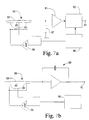
- a basic block diagram of the feedback control circuit for a feedback-controlled silicon differential pressure transducer is shown. It must be noted, however, that the electrode structure illustrated in the diagrams with only one fixed electrode 74 to both sides of the transducing diaphragm 75 is not suited for a practical implementation of the arrangement according to the invention. Therefore, the diagrams must be understood as mere illustrations of the feedback principle alone. Accordingly, a voltage proportional to the difference of the sensing capacitors is detected from the transducer. The detected voltage is fed to a feedback control circuit whose output voltage is taken back to the transducer. In a force equilibrium, the force accomplished by means of the electric field compensates the mechanical force imposed by the differential pressure on the transducing diaphragm. This principle was already discussed in detail in the general part of the description above.
- an AC voltage is taken from a drive signal source 88 to the fixed electrodes 85 and 84 of an asymmetric transducer structure 80.
- the polarity of the signal taken to electrodes 84 is inverted by means of an inverting amplifier 86.
- the transducing membrane 83 is taken via a resistor 87 to ground potential.
- the capacitance difference of the capacitors formed between the transducing diaphragm 83 and the electrodes 85 and 84 is detected by means of a phase-sensitive detector, whose output signal 91 is taken to a feedback circuit (not shown) suited to control the transducing diaphragm 83 to a desired geometric state.
- an electric pulse generator 90 is employed to feed the electrodes 84 and 85 with a sensing voltage so that the pulse polarity to the electrode 84 is inverted by means of an inverting amplifier.
- the difference of capacitances C 83,85 and C 83,84 is detected by means of a charge amplifier 89, whose output 91 gives a voltage proportional to the charge difference of the capacitances, and this output voltage information is used for the feedback control of the transducer 80 via electrostatic forces imposed on the transducing element.
- FIGs. 8a and 8b An example for the application of the technique according to the invention to a more complicated control of transducing diaphragm contour is given in Figs. 8a and 8b illustrating an undulated diaphragm in which the undulations are generated onto an initially flat diaphragm.
- Such an arrangement is in principle realizable in two different manners:
- a term effectivearea may be defined for the fixed electrodes of the transducer structure.
Landscapes
- Physics & Mathematics (AREA)
- General Physics & Mathematics (AREA)
- Electromagnetism (AREA)
- Engineering & Computer Science (AREA)
- Power Engineering (AREA)
- Measuring Fluid Pressure (AREA)
- Feedback Control In General (AREA)
- Transducers For Ultrasonic Waves (AREA)
Description
Claims (9)
- A capacitive transducer feedback-controlled by means of electrostatic force, comprisingcharacterised in thata body part (18),a dynamically moving transducer element sensitive to the variable being measured, said element being attached to said body part (18), said element further being electrically conductive at least on its surface to form a first electrode (9,75,83,97) of the transducer, said transducer element comprising a substantially planar diaphragm (9,75,83,97) sensitive to the difference of pressures applied to the two sides of said diaphragm, andat least two second electrodes (5,6,7,8) which are provided on the body part (18) and which are aligned substantially concentrically and substantially parallel to the transducing element (9,75,83,97) and placed on the same side with regard to the transducing element (9,75,83,97),the second electrodes (5,6,7,8) have at least substantially equal effective areas to enable measuring of the profile of the transducing element (9,75,83,97) and controlling of the same to an exactly defined geometric state, and in that a feedback control means is arranged to keep the diaphragm unflexed.
- A transducer as defined in claim 1,
characterised in that the second, planar electrodes (5,6,7,8) have at least substantially equal areas. - A transducer as defined in claim 1 or claim 2, characterised in that the second, planar electrodes (1,2,5,6,7,8) are constituted by a circular centre electrode (2) and at least one annular electrode (1) encircling said centre electrode.
- A transducer as defined in any of claims 1, 2 or 3, characterised in that the second, planar electrodes (3,4,5,6,7,8) comprise a square centre electrode (4) which is enclosed by at least one square-frame-shaped electrode (3).
- A transducer as defined in any of claims 1, 2 or 3, characterised in that the second electrodes (5,6,7,8,21,22) comprise a circular centre electrode (22) enclosed by at least one electrode (21) with a circular inner perimeter and square outer perimeter.
- A transducer as defined in any foregoing claims, characterised in that the second electrodes (5, 6, 7,8) are placed on both sides with regard to the transducing element (9).
- A transducer as defined in claim 1,
characterised in that said second electrodes are fabricated into a multiple element matrix which is further organised by electrical connections into at least two sets of subelectrodes with essentially equal effective areas. - A method for controlling a transducer suited for feedback-control by means of electrostatic force, said transducer comprisingcharacterised in that said method comprises aiming to control the transducing element (9,75,83,97) to its nondeviated position,a body part (18),a dynamically moving transducer element sensitive to the variable being measured, said element being attached to said body part (18), said element further being electrically conductive at least on its surface to form a first electrode (9,75,83,97) of the transducer, said transducer element comprising a substantially planar diaphragm (9,75,83,97) sensitive to the difference of pressures applied to the two sides of said diaphragm, andat least two second electrodes (5,6,7,8) which are provided on the body part (18) and which are aligned substantially parallel to the transducing element (9,75,83,97), and are placed on the same side with regard to the transducing element (9,37),by keeping said transducing element (9,75,83,97) of the transducer in a nondeviated, unflexed state by measuring the profile of the element and then using the profile measurement information for the feedback-control of electrostatic forces imposed between said transducing element (9,75,83,97) and said second electrodes (5,6,7,8).
- A method as defined in claim 8, characterised by adapting said second electrodes (5,6,7,8) to have equal areas, measuring the mutual capacitances (C5,C6) formed between said second electrodes (5,6) and said transducing element (9), and controlling said capacitances to equal values by means of feedback-controlling the electrostatic forces imposed between said transducing element (9) and said second electrodes (5,6).
Applications Claiming Priority (2)
| Application Number | Priority Date | Filing Date | Title |
|---|---|---|---|
| FI933670 | 1993-08-20 | ||
| FI933670A FI93579C (en) | 1993-08-20 | 1993-08-20 | Capacitive encoder feedback with electrostatic force and method for controlling the shape of its active element |
Publications (3)
| Publication Number | Publication Date |
|---|---|
| EP0639755A2 EP0639755A2 (en) | 1995-02-22 |
| EP0639755A3 EP0639755A3 (en) | 1996-01-17 |
| EP0639755B1 true EP0639755B1 (en) | 1998-11-25 |
Family
ID=8538447
Family Applications (1)
| Application Number | Title | Priority Date | Filing Date |
|---|---|---|---|
| EP94306067A Expired - Lifetime EP0639755B1 (en) | 1993-08-20 | 1994-08-17 | Capacitive transducer feedback controlled by means of electrostatic force and method for controlling the profile of the tranducing element in the transducer |
Country Status (7)
| Country | Link |
|---|---|
| US (1) | US5531128A (en) |
| EP (1) | EP0639755B1 (en) |
| JP (1) | JP3369316B2 (en) |
| CA (1) | CA2130364C (en) |
| DE (1) | DE69414783T2 (en) |
| FI (1) | FI93579C (en) |
| NO (1) | NO309300B1 (en) |
Families Citing this family (23)
| Publication number | Priority date | Publication date | Assignee | Title |
|---|---|---|---|---|
| FI93580C (en) * | 1993-10-08 | 1995-04-25 | Vaisala Oy | Method and apparatus for feedback of an asymmetric pressure differential sensor |
| FI102783B1 (en) * | 1994-12-22 | 1999-02-15 | Vaisala Oyj | Method for linearizing a current velocity sensor and linearized current velocity measuring device |
| US5916179A (en) * | 1997-04-18 | 1999-06-29 | Sharrock; Nigel | System and method for reducing iatrogenic damage to nerves |
| US20040099061A1 (en) * | 1997-12-22 | 2004-05-27 | Mks Instruments | Pressure sensor for detecting small pressure differences and low pressures |
| FI105237B (en) * | 1998-06-24 | 2000-06-30 | Valtion Teknillinen | Silicon micro mechanical balance |
| FI20000339A7 (en) | 2000-02-16 | 2001-08-17 | Nokia Corp | Micromechanical adjustable capacitor and integrated adjustable resonator |
| DE10122912A1 (en) * | 2001-05-11 | 2002-11-21 | Infineon Technologies Ag | Device and method for generating a predetermined positional relationship between two electrodes that are movable relative to one another |
| US6813954B2 (en) * | 2001-05-25 | 2004-11-09 | Panametrics, Inc. | High sensitivity pressure sensor with long term stability |
| EP1407464B1 (en) | 2001-07-17 | 2011-03-09 | SMC Kabushiki Kaisha | Micro-electromechanical sensor |
| DE60319770T2 (en) | 2002-05-29 | 2009-04-23 | Imec Vzw, Interuniversitair Microelectronica Centrum Vzw | Apparatus and method for determining the performance of micromachines or microelectromechanical components |
| EP1367405B1 (en) * | 2002-05-29 | 2008-03-19 | IMEC vzw, Interuniversitair Microelectronica Centrum vzw | Apparatus and method for determining the performance of micro machined or microelectromechanical devices |
| EP1382977A1 (en) * | 2002-07-19 | 2004-01-21 | IMEC vzw, Interuniversitair Microelectronica Centrum vzw | Apparatus and method for determining the performance of micro machines or microelectromechanical devices |
| FR2858854B1 (en) * | 2003-08-13 | 2005-12-16 | Sercel Rech Const Elect | ACCELEROMETER WITH VIBRATION PARASITES REDUCED BY IMPROVED REMINDER |
| US6877382B1 (en) * | 2003-10-20 | 2005-04-12 | Robert D Gourlay | Inhalation detector |
| JP4103877B2 (en) * | 2004-09-22 | 2008-06-18 | セイコーエプソン株式会社 | Electrostatic ultrasonic transducer and ultrasonic speaker |
| US7137301B2 (en) | 2004-10-07 | 2006-11-21 | Mks Instruments, Inc. | Method and apparatus for forming a reference pressure within a chamber of a capacitance sensor |
| US7141447B2 (en) | 2004-10-07 | 2006-11-28 | Mks Instruments, Inc. | Method of forming a seal between a housing and a diaphragm of a capacitance sensor |
| JP5169608B2 (en) * | 2008-08-08 | 2013-03-27 | 富士電機株式会社 | Capacitance pressure sensor and capacitance pressure detector |
| DE102012111533A1 (en) * | 2012-11-28 | 2014-05-28 | Endress + Hauser Gmbh + Co. Kg | Pressure measuring cell |
| CN104555882B (en) * | 2013-10-10 | 2016-03-23 | 原相科技股份有限公司 | Microcomputer electric component and micro electronmechanical collocation structure |
| FR3054861B1 (en) * | 2016-08-02 | 2019-08-23 | Zodiac Aerotechnics | METHOD OF CONTROLLING AN ONDULATING MEMBRANE PUMP, AND PILOT SYSTEM OF AN INJUSTING MEMBRANE PUMP |
| AT520420B1 (en) * | 2017-08-09 | 2019-07-15 | Anton Paar Gmbh | Capacitive path measuring device for measuring a path information of a probe body |
| DE102017131066A1 (en) * | 2017-12-22 | 2019-06-27 | Endress+Hauser SE+Co. KG | Method of providing calibrated pressure transducers |
Citations (2)
| Publication number | Priority date | Publication date | Assignee | Title |
|---|---|---|---|---|
| US4831492A (en) * | 1987-05-08 | 1989-05-16 | Vaisala Oy | Capacitor construction for use in pressure transducers |
| US5095750A (en) * | 1988-04-01 | 1992-03-17 | Hitachi, Ltd. | Accelerometer with pulse width modulation |
Family Cites Families (19)
| Publication number | Priority date | Publication date | Assignee | Title |
|---|---|---|---|---|
| US3229530A (en) * | 1960-12-12 | 1966-01-18 | North American Aviation Inc | Accelerometer |
| GB1138401A (en) * | 1965-05-06 | 1969-01-01 | Mallory & Co Inc P R | Bonding |
| US3602047A (en) * | 1969-06-24 | 1971-08-31 | Kistler Instr Corp | Servo pressure transducer |
| JPS5516228A (en) * | 1978-07-21 | 1980-02-04 | Hitachi Ltd | Capacity type sensor |
| US4340409A (en) * | 1979-04-16 | 1982-07-20 | The Bendix Corporation | Method of fabricating a pressure sensor |
| US4386453A (en) * | 1979-09-04 | 1983-06-07 | Ford Motor Company | Method for manufacturing variable capacitance pressure transducers |
| US4332000A (en) * | 1980-10-03 | 1982-05-25 | International Business Machines Corporation | Capacitive pressure transducer |
| US4390925A (en) * | 1981-08-26 | 1983-06-28 | Leeds & Northrup Company | Multiple-cavity variable capacitance pressure transducer |
| EP0118359B1 (en) * | 1983-02-28 | 1987-05-20 | Office National d'Etudes et de Recherches Aérospatiales (O.N.E.R.A.) | Electrostatic accelerometer |
| FI69211C (en) * | 1984-02-21 | 1985-12-10 | Vaisala Oy | CAPACITIVE STYCLE |
| FI74350C (en) * | 1984-02-21 | 1988-01-11 | Vaisala Oy | Capacitive absolute pressure sensor. |
| FI71015C (en) * | 1984-02-21 | 1986-10-27 | Vaisala Oy | TEMPERATUROBEROENDE KAPACITIV TRYCKGIVARE |
| US4679434A (en) * | 1985-07-25 | 1987-07-14 | Litton Systems, Inc. | Integrated force balanced accelerometer |
| US5211051A (en) * | 1987-11-09 | 1993-05-18 | California Institute Of Technology | Methods and apparatus for improving sensor performance |
| US5048165A (en) * | 1989-01-30 | 1991-09-17 | Dresser Industries, Inc. | Method for controlling the sensitivity and linearity of capacitive transducer systems |
| US5019783A (en) * | 1989-01-30 | 1991-05-28 | Dresser Industries, Inc. | Precision transducer circuit and linearization method |
| US5028876A (en) * | 1989-01-30 | 1991-07-02 | Dresser Industries, Inc. | Precision capacitive transducer circuits and methods |
| US4996627A (en) * | 1989-01-30 | 1991-02-26 | Dresser Industries, Inc. | High sensitivity miniature pressure transducer |
| US5085070A (en) * | 1990-02-07 | 1992-02-04 | At&T Bell Laboratories | Capacitive force-balance system for measuring small forces and pressures |
-
1993
- 1993-08-20 FI FI933670A patent/FI93579C/en active IP Right Grant
-
1994
- 1994-08-17 DE DE69414783T patent/DE69414783T2/en not_active Expired - Lifetime
- 1994-08-17 EP EP94306067A patent/EP0639755B1/en not_active Expired - Lifetime
- 1994-08-18 CA CA002130364A patent/CA2130364C/en not_active Expired - Fee Related
- 1994-08-19 US US08/293,463 patent/US5531128A/en not_active Expired - Lifetime
- 1994-08-19 NO NO943069A patent/NO309300B1/en not_active IP Right Cessation
- 1994-08-22 JP JP19666094A patent/JP3369316B2/en not_active Expired - Fee Related
Patent Citations (2)
| Publication number | Priority date | Publication date | Assignee | Title |
|---|---|---|---|---|
| US4831492A (en) * | 1987-05-08 | 1989-05-16 | Vaisala Oy | Capacitor construction for use in pressure transducers |
| US5095750A (en) * | 1988-04-01 | 1992-03-17 | Hitachi, Ltd. | Accelerometer with pulse width modulation |
Non-Patent Citations (1)
| Title |
|---|
| Navigation, vol. 38, no. 1, spring 1991; K. Warren: "Electrostatically Force-Balanced Silicon Accelerometer" * |
Also Published As
| Publication number | Publication date |
|---|---|
| FI933670A0 (en) | 1993-08-20 |
| US5531128A (en) | 1996-07-02 |
| NO943069D0 (en) | 1994-08-19 |
| FI93579B (en) | 1995-01-13 |
| NO943069L (en) | 1995-02-21 |
| DE69414783T2 (en) | 1999-07-29 |
| CA2130364C (en) | 2002-01-22 |
| EP0639755A2 (en) | 1995-02-22 |
| CA2130364A1 (en) | 1995-02-21 |
| JPH0792046A (en) | 1995-04-07 |
| DE69414783D1 (en) | 1999-01-07 |
| NO309300B1 (en) | 2001-01-08 |
| EP0639755A3 (en) | 1996-01-17 |
| FI93579C (en) | 1995-04-25 |
| JP3369316B2 (en) | 2003-01-20 |
Similar Documents
| Publication | Publication Date | Title |
|---|---|---|
| US5531128A (en) | Capacitive transducer feedback-controlled by means of electrostatic force and method for controlling the profile of the transducing element in the transducer | |
| US4920801A (en) | Accelerometer | |
| US4584885A (en) | Capacitive detector for transducers | |
| US6496348B2 (en) | Method to force-balance capacitive transducers | |
| US6119518A (en) | Angular velocity sensor | |
| US4572006A (en) | Load cells | |
| US4711128A (en) | Micromachined accelerometer with electrostatic return | |
| EP0795122B1 (en) | Sensor with separate actuator and sense fingers | |
| KR910006670B1 (en) | Untouching type pattern sensor improved | |
| US4941354A (en) | Tri-axial accelerometers | |
| EP0647840B1 (en) | Method and apparatus for feedbackcontrol of an asymmetric differential pressure transducer | |
| JPH05256870A (en) | Small-sized silicon accelerometer and its method | |
| GB2158579A (en) | Angular rate sensor system | |
| US6658938B2 (en) | Electret transducer | |
| US5211051A (en) | Methods and apparatus for improving sensor performance | |
| KR100236486B1 (en) | Capacitive acceleration sensor | |
| US4712083A (en) | Position sensor | |
| US4533219A (en) | Tip-tilt mirror actuation system employing a single control voltage | |
| US20050145030A1 (en) | Apparatus for and method of sensing a measured input | |
| US5886259A (en) | Axis aligned rate and acceleration sensor | |
| JPH03293565A (en) | Pwm electrostatic servo type accelerometer | |
| GB2149570A (en) | Piezoelectric transducer | |
| US4082990A (en) | Electrostatic pickoff and torquer | |
| JP2581324B2 (en) | Acceleration sensor | |
| JP2807919B2 (en) | Acceleration sensor |
Legal Events
| Date | Code | Title | Description |
|---|---|---|---|
| PUAI | Public reference made under article 153(3) epc to a published international application that has entered the european phase |
Free format text: ORIGINAL CODE: 0009012 |
|
| AK | Designated contracting states |
Kind code of ref document: A2 Designated state(s): CH DE DK FR GB LI NL SE |
|
| PUAL | Search report despatched |
Free format text: ORIGINAL CODE: 0009013 |
|
| AK | Designated contracting states |
Kind code of ref document: A3 Designated state(s): CH DE DK FR GB LI NL SE |
|
| RHK1 | Main classification (correction) |
Ipc: G01P 15/13 |
|
| K1C1 | Correction of patent application (title page) published |
Effective date: 19950222 |
|
| 17P | Request for examination filed |
Effective date: 19960617 |
|
| 17Q | First examination report despatched |
Effective date: 19970612 |
|
| GRAG | Despatch of communication of intention to grant |
Free format text: ORIGINAL CODE: EPIDOS AGRA |
|
| GRAG | Despatch of communication of intention to grant |
Free format text: ORIGINAL CODE: EPIDOS AGRA |
|
| GRAH | Despatch of communication of intention to grant a patent |
Free format text: ORIGINAL CODE: EPIDOS IGRA |
|
| GRAH | Despatch of communication of intention to grant a patent |
Free format text: ORIGINAL CODE: EPIDOS IGRA |
|
| GRAA | (expected) grant |
Free format text: ORIGINAL CODE: 0009210 |
|
| AK | Designated contracting states |
Kind code of ref document: B1 Designated state(s): CH DE DK FR GB LI NL SE |
|
| PG25 | Lapsed in a contracting state [announced via postgrant information from national office to epo] |
Ref country code: SE Free format text: THE PATENT HAS BEEN ANNULLED BY A DECISION OF A NATIONAL AUTHORITY Effective date: 19981125 Ref country code: NL Free format text: LAPSE BECAUSE OF FAILURE TO SUBMIT A TRANSLATION OF THE DESCRIPTION OR TO PAY THE FEE WITHIN THE PRESCRIBED TIME-LIMIT Effective date: 19981125 Ref country code: LI Free format text: LAPSE BECAUSE OF FAILURE TO SUBMIT A TRANSLATION OF THE DESCRIPTION OR TO PAY THE FEE WITHIN THE PRESCRIBED TIME-LIMIT Effective date: 19981125 Ref country code: CH Free format text: LAPSE BECAUSE OF FAILURE TO SUBMIT A TRANSLATION OF THE DESCRIPTION OR TO PAY THE FEE WITHIN THE PRESCRIBED TIME-LIMIT Effective date: 19981125 |
|
| REG | Reference to a national code |
Ref country code: CH Ref legal event code: EP |
|
| REF | Corresponds to: |
Ref document number: 69414783 Country of ref document: DE Date of ref document: 19990107 |
|
| RAP2 | Party data changed (patent owner data changed or rights of a patent transferred) |
Owner name: VAISALA OYJ |
|
| PG25 | Lapsed in a contracting state [announced via postgrant information from national office to epo] |
Ref country code: DK Free format text: LAPSE BECAUSE OF FAILURE TO SUBMIT A TRANSLATION OF THE DESCRIPTION OR TO PAY THE FEE WITHIN THE PRESCRIBED TIME-LIMIT Effective date: 19990225 |
|
| ET | Fr: translation filed | ||
| NLT2 | Nl: modifications (of names), taken from the european patent patent bulletin |
Owner name: VAISALA OYJ |
|
| NLV1 | Nl: lapsed or annulled due to failure to fulfill the requirements of art. 29p and 29m of the patents act | ||
| REG | Reference to a national code |
Ref country code: CH Ref legal event code: PL |
|
| PLBE | No opposition filed within time limit |
Free format text: ORIGINAL CODE: 0009261 |
|
| STAA | Information on the status of an ep patent application or granted ep patent |
Free format text: STATUS: NO OPPOSITION FILED WITHIN TIME LIMIT |
|
| 26N | No opposition filed | ||
| REG | Reference to a national code |
Ref country code: GB Ref legal event code: IF02 |
|
| PGFP | Annual fee paid to national office [announced via postgrant information from national office to epo] |
Ref country code: GB Payment date: 20090827 Year of fee payment: 16 Ref country code: DE Payment date: 20090821 Year of fee payment: 16 |
|
| GBPC | Gb: european patent ceased through non-payment of renewal fee |
Effective date: 20100817 |
|
| REG | Reference to a national code |
Ref country code: FR Ref legal event code: ST Effective date: 20110502 |
|
| REG | Reference to a national code |
Ref country code: DE Ref legal event code: R119 Ref document number: 69414783 Country of ref document: DE Effective date: 20110301 |
|
| PG25 | Lapsed in a contracting state [announced via postgrant information from national office to epo] |
Ref country code: DE Free format text: LAPSE BECAUSE OF NON-PAYMENT OF DUE FEES Effective date: 20110301 Ref country code: FR Free format text: LAPSE BECAUSE OF NON-PAYMENT OF DUE FEES Effective date: 20100831 |
|
| PG25 | Lapsed in a contracting state [announced via postgrant information from national office to epo] |
Ref country code: GB Free format text: LAPSE BECAUSE OF NON-PAYMENT OF DUE FEES Effective date: 20100817 |
|
| PGFP | Annual fee paid to national office [announced via postgrant information from national office to epo] |
Ref country code: FR Payment date: 20090914 Year of fee payment: 16 |