EP0637520B1 - Suspension arm made of fiber reinforced plastic and manufacturing method thereof - Google Patents
Suspension arm made of fiber reinforced plastic and manufacturing method thereof Download PDFInfo
- Publication number
- EP0637520B1 EP0637520B1 EP94112137A EP94112137A EP0637520B1 EP 0637520 B1 EP0637520 B1 EP 0637520B1 EP 94112137 A EP94112137 A EP 94112137A EP 94112137 A EP94112137 A EP 94112137A EP 0637520 B1 EP0637520 B1 EP 0637520B1
- Authority
- EP
- European Patent Office
- Prior art keywords
- side connecting
- arm
- jig
- arm member
- vehicle
- Prior art date
- Legal status (The legal status is an assumption and is not a legal conclusion. Google has not performed a legal analysis and makes no representation as to the accuracy of the status listed.)
- Expired - Lifetime
Links
- 239000000725 suspension Substances 0.000 title claims description 30
- 238000004519 manufacturing process Methods 0.000 title claims description 26
- 229920002430 Fibre-reinforced plastic Polymers 0.000 title claims description 13
- 239000011151 fibre-reinforced plastic Substances 0.000 title claims description 13
- 239000003365 glass fiber Substances 0.000 claims description 40
- 239000000835 fiber Substances 0.000 claims description 33
- 229920005989 resin Polymers 0.000 claims description 11
- 239000011347 resin Substances 0.000 claims description 11
- 238000004804 winding Methods 0.000 claims description 11
- 238000005452 bending Methods 0.000 claims description 8
- 239000003822 epoxy resin Substances 0.000 claims description 5
- 229920000647 polyepoxide Polymers 0.000 claims description 5
- 230000007423 decrease Effects 0.000 claims description 4
- 238000003825 pressing Methods 0.000 claims description 3
- 229920003023 plastic Polymers 0.000 description 20
- 239000004033 plastic Substances 0.000 description 20
- 230000035882 stress Effects 0.000 description 12
- 230000014509 gene expression Effects 0.000 description 10
- 238000009730 filament winding Methods 0.000 description 8
- 241001247986 Calotropis procera Species 0.000 description 7
- 238000000034 method Methods 0.000 description 6
- 239000011152 fibreglass Substances 0.000 description 4
- 230000032683 aging Effects 0.000 description 2
- 230000015572 biosynthetic process Effects 0.000 description 1
- 230000006835 compression Effects 0.000 description 1
- 238000007906 compression Methods 0.000 description 1
- 238000010276 construction Methods 0.000 description 1
- 238000005336 cracking Methods 0.000 description 1
- 230000003247 decreasing effect Effects 0.000 description 1
- 230000006866 deterioration Effects 0.000 description 1
- 230000000694 effects Effects 0.000 description 1
- 239000000463 material Substances 0.000 description 1
- 238000012986 modification Methods 0.000 description 1
- 230000004048 modification Effects 0.000 description 1
Images



Classifications
-
- B—PERFORMING OPERATIONS; TRANSPORTING
- B29—WORKING OF PLASTICS; WORKING OF SUBSTANCES IN A PLASTIC STATE IN GENERAL
- B29D—PRODUCING PARTICULAR ARTICLES FROM PLASTICS OR FROM SUBSTANCES IN A PLASTIC STATE
- B29D99/00—Subject matter not provided for in other groups of this subclass
- B29D99/0003—Producing profiled members, e.g. beams
- B29D99/0007—Producing profiled members, e.g. beams having a variable cross-section
-
- B—PERFORMING OPERATIONS; TRANSPORTING
- B29—WORKING OF PLASTICS; WORKING OF SUBSTANCES IN A PLASTIC STATE IN GENERAL
- B29C—SHAPING OR JOINING OF PLASTICS; SHAPING OF MATERIAL IN A PLASTIC STATE, NOT OTHERWISE PROVIDED FOR; AFTER-TREATMENT OF THE SHAPED PRODUCTS, e.g. REPAIRING
- B29C53/00—Shaping by bending, folding, twisting, straightening or flattening; Apparatus therefor
- B29C53/56—Winding and joining, e.g. winding spirally
- B29C53/564—Winding and joining, e.g. winding spirally for making non-tubular articles
-
- B—PERFORMING OPERATIONS; TRANSPORTING
- B29—WORKING OF PLASTICS; WORKING OF SUBSTANCES IN A PLASTIC STATE IN GENERAL
- B29C—SHAPING OR JOINING OF PLASTICS; SHAPING OF MATERIAL IN A PLASTIC STATE, NOT OTHERWISE PROVIDED FOR; AFTER-TREATMENT OF THE SHAPED PRODUCTS, e.g. REPAIRING
- B29C70/00—Shaping composites, i.e. plastics material comprising reinforcements, fillers or preformed parts, e.g. inserts
- B29C70/68—Shaping composites, i.e. plastics material comprising reinforcements, fillers or preformed parts, e.g. inserts by incorporating or moulding on preformed parts, e.g. inserts or layers, e.g. foam blocks
- B29C70/72—Encapsulating inserts having non-encapsulated projections, e.g. extremities or terminal portions of electrical components
-
- B—PERFORMING OPERATIONS; TRANSPORTING
- B29—WORKING OF PLASTICS; WORKING OF SUBSTANCES IN A PLASTIC STATE IN GENERAL
- B29C—SHAPING OR JOINING OF PLASTICS; SHAPING OF MATERIAL IN A PLASTIC STATE, NOT OTHERWISE PROVIDED FOR; AFTER-TREATMENT OF THE SHAPED PRODUCTS, e.g. REPAIRING
- B29C70/00—Shaping composites, i.e. plastics material comprising reinforcements, fillers or preformed parts, e.g. inserts
- B29C70/68—Shaping composites, i.e. plastics material comprising reinforcements, fillers or preformed parts, e.g. inserts by incorporating or moulding on preformed parts, e.g. inserts or layers, e.g. foam blocks
- B29C70/86—Incorporated in coherent impregnated reinforcing layers, e.g. by winding
-
- B—PERFORMING OPERATIONS; TRANSPORTING
- B60—VEHICLES IN GENERAL
- B60G—VEHICLE SUSPENSION ARRANGEMENTS
- B60G7/00—Pivoted suspension arms; Accessories thereof
- B60G7/001—Suspension arms, e.g. constructional features
-
- B—PERFORMING OPERATIONS; TRANSPORTING
- B60—VEHICLES IN GENERAL
- B60G—VEHICLE SUSPENSION ARRANGEMENTS
- B60G2204/00—Indexing codes related to suspensions per se or to auxiliary parts
- B60G2204/40—Auxiliary suspension parts; Adjustment of suspensions
- B60G2204/416—Ball or spherical joints
-
- B—PERFORMING OPERATIONS; TRANSPORTING
- B60—VEHICLES IN GENERAL
- B60G—VEHICLE SUSPENSION ARRANGEMENTS
- B60G2206/00—Indexing codes related to the manufacturing of suspensions: constructional features, the materials used, procedures or tools
- B60G2206/01—Constructional features of suspension elements, e.g. arms, dampers, springs
- B60G2206/10—Constructional features of arms
-
- B—PERFORMING OPERATIONS; TRANSPORTING
- B60—VEHICLES IN GENERAL
- B60G—VEHICLE SUSPENSION ARRANGEMENTS
- B60G2206/00—Indexing codes related to the manufacturing of suspensions: constructional features, the materials used, procedures or tools
- B60G2206/01—Constructional features of suspension elements, e.g. arms, dampers, springs
- B60G2206/10—Constructional features of arms
- B60G2206/124—Constructional features of arms the arm having triangular or Y-shape, e.g. wishbone
-
- B—PERFORMING OPERATIONS; TRANSPORTING
- B60—VEHICLES IN GENERAL
- B60G—VEHICLE SUSPENSION ARRANGEMENTS
- B60G2206/00—Indexing codes related to the manufacturing of suspensions: constructional features, the materials used, procedures or tools
- B60G2206/01—Constructional features of suspension elements, e.g. arms, dampers, springs
- B60G2206/70—Materials used in suspensions
- B60G2206/71—Light weight materials
- B60G2206/7101—Fiber-reinforced plastics [FRP]
-
- B—PERFORMING OPERATIONS; TRANSPORTING
- B60—VEHICLES IN GENERAL
- B60G—VEHICLE SUSPENSION ARRANGEMENTS
- B60G2206/00—Indexing codes related to the manufacturing of suspensions: constructional features, the materials used, procedures or tools
- B60G2206/01—Constructional features of suspension elements, e.g. arms, dampers, springs
- B60G2206/80—Manufacturing procedures
- B60G2206/81—Shaping
- B60G2206/8101—Shaping by casting
Definitions
- the present invention relates to a suspension arm of a vehicle, according to the preamble of the patent claim 1 and to a manufacturing method according to the patent claims 7 and 13.
- An upper arm as a suspension arm, made of fiber reinforced plastic (FRP) is described in the TOYOTA Technical Report, April, 1989.
- This upper arm is adapted to connect a ball joint comprising a wheel-side connecting member connected to a wheel to a rubber bush comprising a vehicle-side connecting member connected to a vehicle body.
- FRP fiber reinforced plastic
- the above-mentioned FRP upper arm has an increased rigidity in a side direction of a vehicle without increased rigidity in a longitudinal direction of the vehicle, and thereby riding comfort and stability and controllability of the vehicle are improved.
- the FRP upper arm has a flat A-shaped contour so as to obtain a high strength against a load applied in the longitudinal direction. Additionally, the FRP upper arm has three different patterns of fibers incorporated therein, the fibers being wound on the ball joint, run through an arm portion and then wound on a bush portion.
- the FRP upper arm is made to be a rigid member, there is no flexibility in the longitudinal direction of the vehicle. Accordingly, in order to absorb the load applied in the longitudinal direction, a rubber bush having an elasticity has to be provided on each end of the FRP arm. The rubber bush is required to show a predetermined elastic property even after a long service time.
- the FRP upper arm has the A-shaped contour
- tensile and compression stresses due to the load applied in the longitudinal direction increase at portions of the FRP upper arm near the ball joint and the rubber bush.
- rigidity of an entire arm has to be increased, and thus a weight of the arm is increased resulting in an increase in material costs.
- a further problem is that construction of the rubber bush is complex and expensive because the rubber bush has to absorb the load in the longitudinal direction so as to provide riding comfort to the vehicle.
- a suspension arm provided between a body and a wheel of a vehicle comprises:
- a more specific object of the present invention is to provide a suspension arm and manufacturing method thereof, which suspension arm has a rigidity in a side direction of the vehicle but has a flexibility in a longitudinal direction.
- a suspension arm provided between a body and a wheel of a vehicle, the suspension arm comprising:
- FIG.1 shows an embodiment of an upper arm 1 according to the present invention.
- the upper arm 1 shown in FIG.1 is an A-shaped upper arm used in a double-wishbone type suspension.
- the upper arm 1 comprises a ball joint 2, bushes 3 and 4, and an arm 5 connecting each of the bushes 3 and 4 to the ball joint 2.
- the ball joint 2 corresponds to the above-mentioned wheel-side connecting member, and has a plastic sleeve 21.
- Each of the bushes 3 and 4 corresponds to the above-mentioned vehicle-side connecting member, and has plastic sleeves 31 and 41, respectively.
- the arm 5 is made of glass fiber reinforced plastic (GFRP), and comprises arm portions 6 and 7. The arm portion 6 extends between the bush 3 and the ball joint 2, and the arm portion 7 extending between the bush 4 and the ball joint 2.
- GFRP glass fiber reinforced plastic
- the arm portion 6 has a flat center portion 61 having a relatively wide width.
- a width b (b') of the arm portion 6 between the bush 3 and the center portion 61 gradually increases toward the center portion 61, while a thickness h (h') gradually decreases, the width b being measured in a vertical direction of a vehicle, the thickness h being measured in a longitudinal direction of the vehicle.
- the shape of the arm portion 6, that is the width b and the thickness h of the arm portion 6, is determined according to the following expression (1) so that a cross sectional area A of the arm portion is constant as shown in FIG.2.
- A b x h
- width b and the thickness h are respectively determined according to the following expression (2) so that a bending stress, generated due to a load P (refer to FIG.2), at each point of the arm portion 6 along an extending direction of the arm portion 6 is constant.
- the width b and the thickness h are determined according to the following expression (4) so that the arm 5 can absorb the bending stress generated due to the load P applied in a longitudinal direction.
- the expression (4) is obtained by twice integrating the result obtained by entering the expressions (1) and (2) into the following expression (3) representing a deflection of the arm portion 6.
- width b and the thickness h are determined to satisfy the following expressions (5), respectively. b ⁇ 2 mm, h ⁇ 100 mm
- the above expressions (5) are applied to maintain the width b being greater than 2 mm because if the width b (or the thickness h) is less than 2 mm, there may occur a problem associated with GFRP. That is, if the width b is less than 2 mm, the arm portion 6 may become cracked or deformed because the arm portion 6 is made of GFRP. Additionally, the arm portion 6 may not have a sufficient strength against fatigue and vibrations.
- a portion 62 of the arm portion 6 near the ball joint 2 has a sufficient rigidity in a side direction as well as in the longitudinal direction.
- a portion 63 near the center portion 61 flexibility in the longitudinal direction is increased.
- the arm portion 6 is flexible in the longitudinal direction but not flexible in the side direction.
- rigidity in the longitudinal direction increases and flexibility in the side direction increases toward the bush 3.
- the arm portion 7 similarly to the arm portion 6, the arm portion 7 has a center portion 71, and a width b' and a thickness h' correspond to the width b and the thickness h of the arm portion 6, respectively.
- the longitudinal load P can be absorbed by the deflection of the arm portions 6 and 7, a vibration in the longitudinal direction is not transmitted to a driver of the vehicle, and thus good riding comfort can be maintained.
- the arm portions 6 and 7 When a side load is applied to the upper arm 1, the arm portions 6 and 7 hardly deflect because the arm portions 6 and 7 are not flexible in that direction, and thus a wheel alignment is not changed. Accordingly, good stability and controllability of the vehicle is obtained.
- the upper arm of the present embodiment according to the present invention is formed so that a uniform stress, which does not exceeds upper stress limit of an elastic range, is generated, and thus there is no permanent deformation of the arm portions 6 and 7 due to repeated stresses. This allows good riding comfort maintained over a long service period as well as a decreased possibility of cracking of the arm portions 6 and 7. Further, due to the uniform stress design of the arm 5, the upper arm can be light weight and compact.
- FIGS.4A and 4B show a filament winding (FW) machine 8 used for winding filament (glass fibers) of the upper arm 1.
- the filament winding machine 8 is capable of winding three upper arms at the same time.
- the filament winding machine 8 comprises a fiber role 80a supplying glass fiber strand 80, a vessel 81a storing epoxy resin 81, a table 82 on which the glass fiber strand 80 is wound in a predetermined shape, motors 84A, 84B and 84C and a controller 85 controlling the motors 84A, 84B and 84C.
- the table 82 is provided with a guide member on either end so as to make the glass fiber strand 80 U-turn at the ends of the table 82.
- Three plastic rings 83 of ball joints are placed on the table 82 between the guide members.
- the motor 84A is provided for moving an end 80b of the glass fiber strand 80 in a longitudinal direction (shown by an arrow A in FIG.4a) of the table 82.
- the motor 84B is provided for moving the end 80b of the glass fiber strand 80 in a direction (shown by an arrow B in FIG.4B) perpendicular to a surface of the table 82.
- the motor 84C is provided for rotating and moving the plastic rings 83 in the direction perpendicular to the surface of the table 82.
- the glass fiber strand 80 is first passed through the vessel 81a so as to impregnate the epoxy resin 81 into the glass fiber strand 80.
- the end 80b of the glass fiber strand 80 is moved by means of the motors 84A and 84B so that the glass fiber strand 80 is wound on each of the plastic rings 83.
- the plastic rings 83 are rotated and moved up and down so that the glass fiber strand 80 is wound on each of the plastic rings 83 in a predetermined condition.
- the continuous glass fiber strand 80 is cut at positions 80c shown in FIG.4A so as to separate the glass fiber strand 80 into 3 portions, each of the portions comprising a single plastic ring 83.
- Each of the portions of the glass fiber strand 80 has an equal length L' as shown in FIG.4A, and has the plastic ring 83 in the center thereof.
- Each of the portions of the glass fiber strand 80 is placed on a lower forming die 86 having a groove 86a formed in a predetermined shape as shown in FIGS.5A and 5B.
- the portion of the glass fiber strand 80 is then pressed into the groove 86a formed on the forming die 86 by means of a roller 87.
- the roller 87 is moved from the plastic ring 83 to an extreme end of the portion of the portions of the glass fiber strand 80 as shown by arrows A and B in FIG.5A.
- the movement of the roller 87 is also shown in FIG.5B which shows a cross sectional view taken along a line C-C of FIG.5A.
- FIG.5C is a cross sectional view taken along a line D-D of FIG.5B.
- each end of the portion of the glass fiber strand 80 is wound on a plastic ring 88 used as a bush as shown in FIGS.6A and 6B.
- An FRP stopper 88a is fitted over the plastic ring 88 as shown in FIG.6C, and then an FRP fastener 88b is applied as shown in FIG.6D so as to fasten the portion of the glass fiber strand 80 over the plastic ring 88.
- FIG.7A The portion of the glass fiber strand 80 is enclosed in a cavity formed by the lower forming die 86 and the upper forming die 89 as shown in FIG.7B which shows a cross sectional view taken along a line A-A of FIG.7A.
- the portion of the glass fiber strand 80 is then heated for 60 min. at 120°C so as to cure the epoxy resin impregnated in the glass fiber strand 80.
- the portion of the glass fiber strand 80 is formed into the upper arm 1 having a predetermined shape determined by the forming dies 86 and 89.
- the upper arm 1 is formed by pressing the portion of the glass fiber strand 80 into the groove 86a of the lower forming die 86 by using a roller 87, and thus the upper arm 1 can be manufactured in a simple process.
- FIGS.8 through 10E of a second embodiment of a manufacturing method of the upper arm 1.
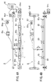
- the upper arm 1 is manufactured by using a plurality of jigs 90, 91A(B), 92A(B), 93(B)A and 94A(B) adapted to hold each portion of the upper arm 1.
- FIGS.8 and 9 show an entire layout of the jigs; FIG.8 is a plan view; FIG.9 is a view taken along a line A-A of FIG.8. In FIGS.8 and 9, for the sake of easy understanding, the complete upper arm 1 is illustrated.
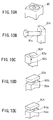
- the ball joint 2 is placed on the jig 90 in which a recess corresponding to a shape of the ball joint 2 is formed as shown in FIG.10A.
- the bush 3 is fixed to the jig 91A by a bolt 91a as shown in FIGS.8 and 10B.
- the bush 4 is fixed, similarly to the bush 3, to the jig 91B. It should be noted that the jigs 90, 91A and 91B are arranged in predetermined positions, so that the ball joint 2 and the bushes 3 and 4 are positioned the same as that of the complete upper arm 1.
- the jig 92A is arranged between the jig 90 and the jig 91A
- the jig 92B is arranged between the jig 90 and the jig 91B.
- Each of the jigs 92A and 92B has gaps 92a and 92b as shown in FIG.10C, the gaps 92a and 92b being arranged vertically.
- the gaps 92a and 92b have widths corresponding to the center portion 61 of the upper arm 1.
- the jig 93A is arranged near the jig 90 between the jig 90 and the jig 92A, the jig 93A having gaps 93a and 93b arranged horizontally as shown in FIG.10D.
- the gaps 93a and 93b have widths corresponding to a corresponding portion of the upper arm 1.
- the jig 94A is arranged near the jig 91A between the jig 90 and the jig 91A, the jig 94A having gaps 94a and 94b arranged horizontally as shown in FIG.10E.
- the gaps 94a and 94b have widths corresponding to a corresponding portion of the upper arm 1.
- the jig 93B is arranged near the jig 90 between the jig 90 and the jig 92B, the jig 93B having gaps similar to the gaps 93a and 93b of the jig 93B.
- the jig 94B is arranged near the jig 91B between the jig 90 and the jig 91B, the jig 94B having gaps similar to the gaps 94a and 94b of the jig 94A.
- a glass fiber strand 100 impregnated with resin is wound on the plastic sleeve 21 of the ball joint 2, and then the glass fiber strand 100 is passed through the gap 93a of the jig 93A, the gap 92a of the jig 92A, and the gap 94a of the jig 94A, in that order, and then the glass fiber strand 100 is wound on the plastic sleeve 31 of the bush 3.
- the glass fiber strand After being wound on the plastic sleeve 31, the glass fiber strand is passed through the gap 94b of the jig 94A, the gap 92b of the jig 92A, and the gap 93b of the jig 93A, in this turn, and then the glass fiber strand is wound on the plastic sleeve 21 of the ball joint 2. After the glass fiber strand is wound on the plastic sleeve 21 for the second time, the same process is performed for the other side of the arm formed with the jigs 93B, 92B, 94B and 91B.
- the shape of the glass fiber strand winding formed by the present embodiment of the manufacturing method has a narrow width at positions corresponding to the jigs 92A and 92B in directions indicated by arrows B and C, respectively. Additionally, widths corresponding to the jigs 93A, 93B, 94A and 94B are wide relative to the width of portions corresponding to the jigs 92A and 92B.
- the upper arm 1 having a varying cross section can be easily formed by using a plurality of jigs in the glass fiber strand winding process, without altering a winding process of a manufacturing method of a conventional upper arm.
- a suspension arm has a rigidity in the side direction of the vehicle but has a flexibility in the longitudinal direction.
- the suspension arm has a wheel-side connecting member (2) connected to a portion of a wheel, at least one vehicle-side connecting member (3, 4) connected to a portion of a vehicle body, and an arm member (6, 7) extending between the wheel-side connecting member (2) and the vehicle-side connecting member (3).
- a width of a center portion (61, 71) of the arm member (6, 7) is smaller than that of other portions of the arm member( 6, 7), the width being measured in the longitudinal direction of the vehicle, and a thickness of the center portion (61, 71) of the arm member (6, 7) is greater than other portions of the arm member (6, 7), the thickness being measured in a vertical direction of the vehicle.
Landscapes
- Engineering & Computer Science (AREA)
- Mechanical Engineering (AREA)
- Chemical & Material Sciences (AREA)
- Composite Materials (AREA)
- Vehicle Body Suspensions (AREA)
- Moulding By Coating Moulds (AREA)
Description
- a wheel-side connecting member connected to a portion of the wheel;
- at least one vehicle-side connecting member connected to a portion of the vehicle body; and
- an arm member extending between said wheel-side connecting member and said vehicle-side connecting member,
- wherein a width of a center of said arm member
is smaller than that of other portions of said arm member, said width being measured in a longitudinal direction of the vehicle; and a thickness of the center of said arm member is greater than other portions of said arm member, said thickness being measured in a vertical direction of said vehicle.
- a wheel-side connecting member connected to a portion of the wheel;
- at least one vehicle-side connecting member connected to a portion of the vehicle body; and
- an arm member extending between said wheel-side connecting member and said vehicle-side connecting member and having a center therebetween,
- wherein a thickness of said center of said arm
member is greater than other portions of said arm
member lying on each side of said center, said thickness
being measured in a vertical direction of said
vehicle,
characterised in that - a width of said center of said arm member is smaller than that of other portions of said arm member lying on each side of said center, said width being measured in a longitudinal direction of the vehicle.
characterized by
characterized by
- where y is an amount of the deflection.
Claims (18)
- A suspension arm provided between a body and a wheel of a vehicle, the suspension arm comprising:a wheel-side connecting member (2) connected to a portion of the wheel;at least one vehicle-side connecting member (3,4) connected to a portion of the vehicle body; andan arm member (6,7) extending between said wheel-side connecting member and said vehicle-side connecting member and having a center therebetween,wherein a thickness (b) of said center of said arm member is greater than other portions of said arm member lying on each side of said center, said thickness being measured in a vertical direction of said vehicle,
characterised in thata width (h) of said center of said arm member (6,7) is smaller than that of other portions of said arm member lying on each side of said center, said width being measured in a longitudinal direction of the vehicle. - The suspension arm as claimed in claim 1, characterized in that the width of said arm member (6, 7) gradually decreases and the thickness of said arm member (6, 7) gradually increases toward the center from said wheel-side connecting member (2) and from said vehicle-side connecting member (3, 4).
- The suspension arm as claimed in claim 2, characterized in that the width and the thickness of said arm member (6, 7) are determined according to a relationship between a deflection of said arm member and a predetermined load being applied to said arm member (6, 7) in the longitudinal direction so that the deflection does not exceed a predetermined amount when a maximum load is applied to said arm member (6, 7) in the longitudinal direction.
- The suspension arm as claimed in claim 3, characterized in that the width and the thickness of said arm member (6, 7) are determined so that uniform bending stress is generated in said arm member (6, 7) when a load is applied to said arm member (6, 7) in the longitudinal direction.
- The suspension arm as claimed in claim 4, characterized in that two vehicle-side connecting members (3, 4) are provided, and a first arm member (6) extends between one of said vehicle-side connecting members (3, 4) and said wheel-side connecting member (2) and a second arm member (7) extends between the other of vehicle-side connecting members (3, 4) and said wheel-side connecting member (2), said first arm member (6) being the same shape as said second arm member (7).
- The suspension arm as claimed in claim 5, characterized in that said first arm member (6) and said second arm member (7) are made of fiber reinforced plastic.
- A manufacturing method of a suspension arm as defined in claim 1,
characterized bythe steps of:a) preparing a fiber strand (80) wound on said wheel-side connecting member (83), said fiber strand (80) extending from said wheel-side connecting member (83) and having a predetermined length, said fiber strand (80) being impregnated with resin;b) placing said fiber strand (80) in a groove (86a) formed on a lower forming die (86), said groove (86a) having a shape corresponding to said suspension arm;c) pressing said fiber strand (80) into said groove (86a) by using a roller (87), said roller (80) being moved along said fiber strand (80) toward an extreme end of said fiber strand (80) from said wheel-side connecting member (83);d) winding said extreme end of said fiber strand (80) on said vehicle-side connecting member (88);e) placing an upper forming die (89) on said lower forming die (86) so that said fiber strand (80) including said wheel-side connecting member (83) and said vehicle-side connecting member (88) fits in said groove (86a) formed on said lower forming die (86); andf) curing said resin by applying heat to said fiber strand (80). - The manufacturing method as claimed in claim 7, characterized in that the width of said arm member (6, 7) gradually decreases and the thickness of said arm member (6, 7) gradually increases toward the center from said wheel-side connecting member (83) and from said vehicle-side connecting member (88).
- The manufacturing method as claimed in claim 8, characterized in that the width and the thickness of said arm member (6, 7) are determined according to a relationship between a deflection of said arm member (6, 7) and a predetermined load being applied to said arm member (6, 7) in the longitudinal direction so that the deflection does not exceed a predetermined amount when a maximum load is applied to said arm member (6, 7) in the longitudinal direction.
- The manufacturing method as claimed in claim 9, characterized in that the width and the thickness of said arm member (6, 7) are determined so that uniform bending stress is generated in said arm member (6, 7) when a load is applied to said arm member (6, 7) in the longitudinal direction.
- The manufacturing method as claimed in claim 7, characterized in that two vehicle-side connecting members (88) are provided in said suspension arm, and said wheel-side connecting member (83) is positioned at a center of said fiber strand (80) so that each of said vehicle-side connecting members (88) is connected to a respective end of said fiber stand (80).
- The manufacturing method as claimed in claim 7, characterized in that said fiber strand (80) comprises glass fibers, and said resin being impregnated is an epoxy resin.
- A manufacturing method of a suspension arm as defined in claim 1,
characterized bythe steps of:a) preparing a jig including a first jig (90), a second jig (91A, 91B) and a third jig (92a, 92B), said first jig (90) having a recess corresponding to a shape of said wheel-side connecting member (2), said second jig (91A, 91B) having fixing means (91a) for fixing said vehicle-side connecting member, said third jig (92a, 92B) having a gap (92a, 92b) having a width corresponding to a width of a center portion (61, 71) of said arm member (6, 7), the width being in a longitudinal direction of the vehicle;b) arranging said first, second and third jigs so that said jigs (90, 91A, 91B, 92A, 92B) are arranged corresponding to a shape of said suspension arm;c) placing said wheel-side connecting member (2) in said recess of said first jig (90), and fixing said vehicle-side connecting member (3) to said second jig (91A, 91B);d) winding a fiber strand (100) on said wheel-side connecting member (2) and said vehicle-side connecting member (3) by passing through said gap (92a, 92b) of said third jig (92A, 92B), said fiber strand (1001) being impregnated with resin; ande) curing said resin by applying heat. - The manufacturing method as claimed in claim 13, characterized in that the width of said arm member (6, 7) gradually decreases and the thickness of said arm member (6, 7) gradually increases toward the center from said wheel-side connecting member (2) and from said vehicle-side connecting member (3), and wherein said jig further includes a fourth jig (93A, 93B) and a fifth jig (94A, 94B), said fourth jig (93A, 93B) being positioned near said first jig (90) between said first jig (90) and said third jig (92A, 92B), said fifth jig (94A, 94B) being positioned near said second jig (91A, 91B) between said second jig (91A, 91B) and said third jig (92A, 92B), said fourth jig (93A, 93B) and said fifth jig (94A, 94B) having a gap (93a, 93b, 94a, 94b) having a width corresponding to a thickness of a corresponding portion of said arm member (6, 7).
- The manufacturing method as claimed in claim 14, characterized in that the width and the thickness of said arm member (6, 7) are determined according to a relationship between a deflection of said arm member (6, 7) and a predetermined load being applied to said arm member (6, 7) in the longitudinal direction so that the deflection does not exceed a predetermined amount when a maximum load is applied to said arm member (6, 7) in the longitudinal direction.
- The manufacturing method as claimed in claim 15, characterized in that the width and the thickness of said arm member (6, 7) are determined so that uniform bending stress is generated in said arm member (6, 7) when a load is applied to said arm member (6, 7) in the longitudinal direction.
- The manufacturing method as claimed in claim 16, characterized in that two vehicle-side connecting members (3) are provided in said suspension arm, and said wheel-side connecting member (2) is positioned at a center of said fiber strand (100) so that each of said vehicle-side connecting members (3) is connected to a respective end of said fiber stand (100).
- The manufacturing method as claimed in claim 13, characterized in that said fiber strand (100) comprises glass fibers, and said resin being impregnated is an epoxy resin.
Applications Claiming Priority (2)
| Application Number | Priority Date | Filing Date | Title |
|---|---|---|---|
| JP196251/93 | 1993-08-06 | ||
| JP5196251A JPH0747826A (en) | 1993-08-06 | 1993-08-06 | Suspension arm and manufacturing method thereof |
Publications (3)
| Publication Number | Publication Date |
|---|---|
| EP0637520A2 EP0637520A2 (en) | 1995-02-08 |
| EP0637520A3 EP0637520A3 (en) | 1995-11-08 |
| EP0637520B1 true EP0637520B1 (en) | 1998-05-20 |
Family
ID=16354706
Family Applications (1)
| Application Number | Title | Priority Date | Filing Date |
|---|---|---|---|
| EP94112137A Expired - Lifetime EP0637520B1 (en) | 1993-08-06 | 1994-08-03 | Suspension arm made of fiber reinforced plastic and manufacturing method thereof |
Country Status (4)
| Country | Link |
|---|---|
| US (1) | US5556081A (en) |
| EP (1) | EP0637520B1 (en) |
| JP (1) | JPH0747826A (en) |
| DE (1) | DE69410364D1 (en) |
Cited By (1)
| Publication number | Priority date | Publication date | Assignee | Title |
|---|---|---|---|---|
| EP2759423A1 (en) | 2013-01-28 | 2014-07-30 | Gestamp Umformtechnik GmbH | Suspension arm made of fibre-reinforced plastic for a wheel suspension of a vehicle |
Families Citing this family (18)
| Publication number | Priority date | Publication date | Assignee | Title |
|---|---|---|---|---|
| DE19647302C2 (en) * | 1996-11-15 | 1998-11-05 | Daimler Benz Ag | Joint element or arrangement |
| DE19750225A1 (en) | 1997-11-13 | 1999-05-27 | Daimler Chrysler Ag | Guide for a motor vehicle wheel |
| JP2000142051A (en) * | 1998-11-05 | 2000-05-23 | Tokai Rubber Ind Ltd | Suspension arm |
| US6088577A (en) * | 1999-01-13 | 2000-07-11 | Clariti Telecommunications International, Ltd. | Multiple subcarrier communication system |
| US6439586B1 (en) * | 1999-12-01 | 2002-08-27 | Meritor Heavy Vehicle Systems, Llc | Spring band for an axle assembly |
| DE10153970A1 (en) * | 2001-11-06 | 2003-05-22 | Zf Lemfoerder Metallwaren Ag | chassis part |
| US20030230443A1 (en) * | 2002-01-08 | 2003-12-18 | David Cramer | Advanced composite hybrid-electric vehicle |
| DE102011077336A1 (en) * | 2011-06-10 | 2012-12-13 | Zf Friedrichshafen Ag | Wheel suspension element comprising at least one support structure and a handlebar |
| DE102011085029A1 (en) * | 2011-10-21 | 2013-04-25 | Luhn & Pulvermacher - Dittmann & Neuhaus GmbH | Stabilizer in fiber-plastic composite and process for its production |
| DE102013225905A1 (en) * | 2013-12-13 | 2015-06-18 | Bayerische Motoren Werke Aktiengesellschaft | Arrangement of a frame element and a connecting element and method for fastening a connecting element to a frame element |
| WO2017115932A1 (en) | 2015-12-30 | 2017-07-06 | 주식회사 일진 | Hybrid suspension arm for vehicle and manufacturing method therefor |
| DE102016201378B4 (en) * | 2016-01-29 | 2023-12-07 | Zf Friedrichshafen Ag | Chassis component |
| DE102017213564A1 (en) * | 2017-08-04 | 2019-02-07 | Zf Friedrichshafen Ag | Three-point link and manufacturing method for a three-point link |
| DE102017222579A1 (en) * | 2017-12-13 | 2019-06-13 | Schäfer MWN GmbH | Method for producing a component and component |
| DE102019206436A1 (en) * | 2019-05-06 | 2020-11-12 | Schäfer MWN GmbH | Multipoint link for a chassis of a vehicle |
| DE102019206435A1 (en) * | 2019-05-06 | 2020-11-12 | Schäfer MWN GmbH | Multipoint link for a chassis of a vehicle |
| JP7746070B2 (en) | 2021-08-30 | 2025-09-30 | ナブテスコ株式会社 | Joined structure and method for manufacturing the joined structure |
| JP7746069B2 (en) * | 2021-08-30 | 2025-09-30 | ナブテスコ株式会社 | Joined structure and method for manufacturing the joined structure |
Family Cites Families (20)
| Publication number | Priority date | Publication date | Assignee | Title |
|---|---|---|---|---|
| US2615710A (en) * | 1947-06-14 | 1952-10-28 | Tucker Corp | Single leaf spring suspension for automobiles |
| US2827303A (en) * | 1955-11-01 | 1958-03-18 | Thompson Prod Inc | Vehicle suspension and pivot assembly therefor |
| US3376033A (en) * | 1966-05-02 | 1968-04-02 | Gen Motors Corp | Unitized composite spring construction |
| US3445911A (en) * | 1966-08-22 | 1969-05-27 | North American Rockwell | Method of making tapered spring leaf |
| FR2187060A5 (en) * | 1972-05-29 | 1974-01-11 | Nord Ressorts | |
| GB2021731A (en) * | 1978-05-26 | 1979-12-05 | Gkn Group Services Ltd | Leaf springs of fibre-reinforced plastics |
| GB2041489A (en) * | 1978-09-29 | 1980-09-10 | Courtaulds Ltd | Composite elongate element |
| WO1981002141A1 (en) * | 1980-01-25 | 1981-08-06 | Ki Inzh Str Inst | Spring and suspension of a vehicle comprising such spring |
| BR8203375A (en) * | 1981-06-15 | 1983-05-31 | Budd Co | SPRING SHEET FOR SUSPENSION OF RECIPOUS STRUCTURES AND THE PROCESS OF ITS MANUFACTURING |
| FR2516455B1 (en) * | 1981-11-18 | 1986-12-12 | Bertin & Cie | MOTOR VEHICLE SUSPENSION BY ELASTIC BLADE |
| US4772044A (en) * | 1983-08-22 | 1988-09-20 | Booher Benjamin V | Vehicle suspension system with flexible control arm |
| US4509774A (en) * | 1983-08-22 | 1985-04-09 | Booher Benjamin V | Composite control arm apparatus |
| US4575057A (en) * | 1983-12-27 | 1986-03-11 | Ford Motor Company | Filament wound composite material leaf spring |
| GB2154520A (en) * | 1984-02-25 | 1985-09-11 | Ford Motor Co | Vehicle suspension wishbone |
| FR2568167B1 (en) * | 1984-07-25 | 1986-08-29 | Renault | ORIENTED FIBER PREPREGNATES MOLDING METHOD |
| JPS61162326A (en) * | 1985-01-10 | 1986-07-23 | Toyota Motor Corp | Manufacture of fiber reinforced resin structural material |
| US5087503A (en) * | 1989-09-14 | 1992-02-11 | Pacific Coast Composites, Inc. | Composite constant stress beam with gradient fiber distribution |
| JPH03203629A (en) * | 1989-12-29 | 1991-09-05 | Toyota Motor Corp | Preparation of arm structure made of fiber reinforced resin |
| FR2656826B1 (en) * | 1990-01-10 | 1995-07-21 | Mediterranee Const Ind | DEVICE FOR MANUFACTURING COMPOSITE SPRING BLADES. |
| US5063014A (en) * | 1990-05-07 | 1991-11-05 | Aeroquip Corporation | Method for molding trim strips by extrusion molding in an open mold |
-
1993
- 1993-08-06 JP JP5196251A patent/JPH0747826A/en active Pending
-
1994
- 1994-07-28 US US08/281,519 patent/US5556081A/en not_active Expired - Fee Related
- 1994-08-03 EP EP94112137A patent/EP0637520B1/en not_active Expired - Lifetime
- 1994-08-03 DE DE69410364T patent/DE69410364D1/en not_active Expired - Lifetime
Cited By (2)
| Publication number | Priority date | Publication date | Assignee | Title |
|---|---|---|---|---|
| EP2759423A1 (en) | 2013-01-28 | 2014-07-30 | Gestamp Umformtechnik GmbH | Suspension arm made of fibre-reinforced plastic for a wheel suspension of a vehicle |
| US9168801B2 (en) | 2013-01-28 | 2015-10-27 | Gestamp Umformtechnik Gmbh | Transverse link made of fibre-reinforced plastics material for a wheel suspension of a vehicle |
Also Published As
| Publication number | Publication date |
|---|---|
| JPH0747826A (en) | 1995-02-21 |
| EP0637520A3 (en) | 1995-11-08 |
| DE69410364D1 (en) | 1998-06-25 |
| US5556081A (en) | 1996-09-17 |
| EP0637520A2 (en) | 1995-02-08 |
Similar Documents
| Publication | Publication Date | Title |
|---|---|---|
| US5556081A (en) | Suspension arm made of fiber reinforced plastic and manufacturing method thereof | |
| US6811169B2 (en) | Composite spring design that also performs the lower control arm function for a conventional or active suspension system | |
| US4753456A (en) | Vehicle suspension system with flexible control arm | |
| EP0005916A1 (en) | Spring manufacture | |
| US4519591A (en) | Non-metallic leaf spring structure | |
| JPS5926615A (en) | Link device | |
| RU2751565C2 (en) | Four-point suspension arm | |
| CN110997358B (en) | Three-point connecting rod and method for manufacturing same | |
| CA1235154A (en) | Plastic leaf spring with at least one spring-eye body or spring-eye section | |
| GB2375502A (en) | Moulded composite transverse leaf spring | |
| EP2472137B1 (en) | Leaf spring element and leaf spring assembly | |
| GB2082716A (en) | Improvements in or relating to resilient links | |
| US20020101012A1 (en) | Composite bow mono-leaf spring | |
| JPS5986729A (en) | Shock absorber consisting of fiber reinforced material for automobile, etc. | |
| US4732371A (en) | Axle mount construction for a fiber reinforced resin leaf spring | |
| JPS6112467A (en) | Structure for transmitting turning moment and core for winding and molding said structure | |
| JP2768387B2 (en) | Rod structure | |
| JPS61271167A (en) | Steering wheel core material made of fiber reinforced resin and manufacture thereof | |
| US20220212511A1 (en) | Multi-Point Link for an Undercarriage of a Vehicle | |
| WO1986002886A1 (en) | Mountings for springs | |
| JPH03161322A (en) | Manufacture of fiber-reinforced resin product | |
| JPS6139531B2 (en) | ||
| JPH0777231A (en) | FRP leaf spring | |
| EP0040531B1 (en) | Leaf spring and leaf therefor | |
| CN108506396B (en) | Main and auxiliary spring assembly of uniform-section blade |
Legal Events
| Date | Code | Title | Description |
|---|---|---|---|
| PUAI | Public reference made under article 153(3) epc to a published international application that has entered the european phase |
Free format text: ORIGINAL CODE: 0009012 |
|
| 17P | Request for examination filed |
Effective date: 19940803 |
|
| AK | Designated contracting states |
Kind code of ref document: A2 Designated state(s): DE FR GB |
|
| PUAL | Search report despatched |
Free format text: ORIGINAL CODE: 0009013 |
|
| AK | Designated contracting states |
Kind code of ref document: A3 Designated state(s): DE FR GB |
|
| 17Q | First examination report despatched |
Effective date: 19960522 |
|
| GRAG | Despatch of communication of intention to grant |
Free format text: ORIGINAL CODE: EPIDOS AGRA |
|
| GRAG | Despatch of communication of intention to grant |
Free format text: ORIGINAL CODE: EPIDOS AGRA |
|
| GRAH | Despatch of communication of intention to grant a patent |
Free format text: ORIGINAL CODE: EPIDOS IGRA |
|
| GRAH | Despatch of communication of intention to grant a patent |
Free format text: ORIGINAL CODE: EPIDOS IGRA |
|
| GRAA | (expected) grant |
Free format text: ORIGINAL CODE: 0009210 |
|
| AK | Designated contracting states |
Kind code of ref document: B1 Designated state(s): DE FR GB |
|
| REF | Corresponds to: |
Ref document number: 69410364 Country of ref document: DE Date of ref document: 19980625 |
|
| ET | Fr: translation filed | ||
| PG25 | Lapsed in a contracting state [announced via postgrant information from national office to epo] |
Ref country code: GB Free format text: LAPSE BECAUSE OF NON-PAYMENT OF DUE FEES Effective date: 19980820 |
|
| PG25 | Lapsed in a contracting state [announced via postgrant information from national office to epo] |
Ref country code: DE Free format text: LAPSE BECAUSE OF FAILURE TO SUBMIT A TRANSLATION OF THE DESCRIPTION OR TO PAY THE FEE WITHIN THE PRESCRIBED TIME-LIMIT Effective date: 19980821 |
|
| PLBE | No opposition filed within time limit |
Free format text: ORIGINAL CODE: 0009261 |
|
| STAA | Information on the status of an ep patent application or granted ep patent |
Free format text: STATUS: NO OPPOSITION FILED WITHIN TIME LIMIT |
|
| GBPC | Gb: european patent ceased through non-payment of renewal fee |
Effective date: 19980820 |
|
| PG25 | Lapsed in a contracting state [announced via postgrant information from national office to epo] |
Ref country code: FR Free format text: LAPSE BECAUSE OF NON-PAYMENT OF DUE FEES Effective date: 19990430 |
|
| 26N | No opposition filed | ||
| REG | Reference to a national code |
Ref country code: FR Ref legal event code: ST |