EP0637415B1 - System and method for automatic segment resolution on a local area network - Google Patents
System and method for automatic segment resolution on a local area network Download PDFInfo
- Publication number
- EP0637415B1 EP0637415B1 EP94910176A EP94910176A EP0637415B1 EP 0637415 B1 EP0637415 B1 EP 0637415B1 EP 94910176 A EP94910176 A EP 94910176A EP 94910176 A EP94910176 A EP 94910176A EP 0637415 B1 EP0637415 B1 EP 0637415B1
- Authority
- EP
- European Patent Office
- Prior art keywords
- primary
- station
- network
- circuit
- probe
- Prior art date
- Legal status (The legal status is an assumption and is not a legal conclusion. Google has not performed a legal analysis and makes no representation as to the accuracy of the status listed.)
- Expired - Lifetime
Links
- 238000000034 method Methods 0.000 title claims description 22
- 239000000523 sample Substances 0.000 claims abstract description 77
- 230000004044 response Effects 0.000 claims abstract description 20
- 230000000977 initiatory effect Effects 0.000 claims 4
- 238000012544 monitoring process Methods 0.000 abstract description 4
- 238000012545 processing Methods 0.000 description 9
- 238000004891 communication Methods 0.000 description 5
- 230000001419 dependent effect Effects 0.000 description 5
- 239000003999 initiator Substances 0.000 description 5
- 101100172132 Mus musculus Eif3a gene Proteins 0.000 description 4
- 238000010586 diagram Methods 0.000 description 4
- 230000008901 benefit Effects 0.000 description 2
- 238000012986 modification Methods 0.000 description 2
- 230000004048 modification Effects 0.000 description 2
- 230000003190 augmentative effect Effects 0.000 description 1
- 238000001514 detection method Methods 0.000 description 1
- 230000002542 deteriorative effect Effects 0.000 description 1
- 230000000694 effects Effects 0.000 description 1
- 230000007246 mechanism Effects 0.000 description 1
- 238000012806 monitoring device Methods 0.000 description 1
- 230000008569 process Effects 0.000 description 1
Images




Classifications
-
- H—ELECTRICITY
- H04—ELECTRIC COMMUNICATION TECHNIQUE
- H04L—TRANSMISSION OF DIGITAL INFORMATION, e.g. TELEGRAPHIC COMMUNICATION
- H04L43/00—Arrangements for monitoring or testing data switching networks
-
- H—ELECTRICITY
- H04—ELECTRIC COMMUNICATION TECHNIQUE
- H04L—TRANSMISSION OF DIGITAL INFORMATION, e.g. TELEGRAPHIC COMMUNICATION
- H04L12/00—Data switching networks
- H04L12/28—Data switching networks characterised by path configuration, e.g. LAN [Local Area Networks] or WAN [Wide Area Networks]
- H04L12/46—Interconnection of networks
- H04L12/4604—LAN interconnection over a backbone network, e.g. Internet, Frame Relay
- H04L12/462—LAN interconnection over a bridge based backbone
-
- H—ELECTRICITY
- H04—ELECTRIC COMMUNICATION TECHNIQUE
- H04L—TRANSMISSION OF DIGITAL INFORMATION, e.g. TELEGRAPHIC COMMUNICATION
- H04L43/00—Arrangements for monitoring or testing data switching networks
- H04L43/06—Generation of reports
-
- H—ELECTRICITY
- H04—ELECTRIC COMMUNICATION TECHNIQUE
- H04L—TRANSMISSION OF DIGITAL INFORMATION, e.g. TELEGRAPHIC COMMUNICATION
- H04L43/00—Arrangements for monitoring or testing data switching networks
- H04L43/12—Network monitoring probes
Definitions
- the present invention is directed generally to a system and method for resolving the location of a station on a network, and more specifically to a system and method for resolving the location of a station on a segment of a network which is transparently bridged to another segment in that network.
- WO 88/06822 discusses a monitoring system for a local area network in which a monitor manager receives information from monitor units connected to different bases of the local area network.
- a look-up table contains the association between the counters in each monitor unit and characteristics with which they are associated such that packet processing by the monitor units can be performed within a minimum packet time.
- FIG. 1 illustrates a simplified representation of a typical computer communications network 10 in which the apparatus, system and method of the present invention for generating operating statistics may be employed.
- Like reference numerals are employed among the various figures to designate like elements.
- a local area network 10 comprising m segments, a first segment identified by the numeral 12, a second segment identified by the numeral 14a, and an mth segment identified by the numeral 14b. While the present invention may have applications on any network whose segments are transparently bridged to one another, by way of example only, the present invention will be described as implemented on Ethernet. It will be understood by those skilled in the art that the number of segments m is application dependent.
- Each of the segments 12, 14a, and 14b, respectively, is a bus structure implementing the CSMA/CD protocol.
- a bridge 16 is a device which provides the interconnection between segments of a local area network 10. The bridge 16, using one of numerous possible algorithms, makes decisions about switching frames between segments based on the address of a station.
- the bridge 16 monitors a message, it knows on which side of the bridge 16 that the message originated and adds that station address and its position relative to the bridge 16 to its database.
- the bridge 16 when it picks up a new MAC frame on the network 10, searches that database for the destination address contained in that frame. Forwarding of the frame to the other side of the bridge 16 is based on the results of that search.
- the simple algorithm requires no effort nor knowledge by end stations 21a, 25a, 25b to switch frames through the bridges 16, so that operation of the bridges is transparent. If the algorithm is similar to the "learn as you go" method as described above, it may be possible that, until steady-state operation is achieved, the bridge 16 may not properly pass all frames, and thus that possibility must be taken into account in the present invention. It is with bridges 16 which operate transparently to end stations 21a, 25a, and 25b wherein the present invention is preferably implemented.
- a bridged group probe message shown as control block 152 in FIG. 4K may be sent periodically.
- Control block 152 includes a command code field 154 and a request/response indicator field 156. Any other network monitor 20, 24a and 24b which sees the bridge group probe message control block 152 will respond with a similar control block 152 with the response bit set in field 156.
- the bridge group probe message is preferably sent periodically.
- the destination address of that packet may, for example, be the universally administered address ("UAA") of an Ethernet board.
- UUAA universally administered address
- the Ethertype of the packet will be a unique non-routable value assigned to the implementor for this purpose.
- the processing flow starts when a network monitor 20 is requested to resolve ownership of a particular station. That request may come from a host based network monitor (not shown). Such a request may be in the form as shown in FIG. 4E in control block 110 comprising a request code set to resolve station segment in field 112, a primary resolution request indicated in field 114, and the station address in field 116 representing the particular station to be resolved. Alternatively, that request may be generated internally by primary resolver network monitor 20 or be sent from another network monitor 24a or 24b, shown functionally as block 31 in FIG. 2.
- the first network monitor 20 will request primary resolution at step 61.
- the primary resolver network monitor 20 will call the "generating and sending a primary probe" function 34 to generate and send a probe message to the station to be resolved.
- control block 122 in FIG. 4G may be used to perform the function 34.
- the control block 122 comprises a request code field 124 set equal to station segment probe and a probe type field 126 set to primary.
- Function block 42 in FIG. 2 illustrates the function of the primary resolver which receives the summaries in the form of control block 136 from the secondary resolvers.
- Function block 44 illustrates the resolving function as performed by the primary resolver network monitor 20.
- step 68 in FIG. 3 there is a decision made by the primary resolver network monitor 20 as to whether one of the secondary resolvers received no secondary observation reports. If one and only one of the secondary resolvers reports no secondary observations in response to its secondary probe, then that secondary resolver is the owner of the station which was probed.
- a station ownership indication is sent to that secondary resolver which may be in the form of control block 146 in FIG. 4J comprising the station owner field 148 and an address field 150 containing the station that was probed.
- control block 118 contains a request code field 119 signifying that the primary resolver cannot resolve the station segment and an address field 120 indicating the address of the station whose ownership cannot be resolved.
- the primary resolver network monitor 20 determines that the primary resolver network monitor 20 did not receive any primary probe observations in response to the primary probe, processing continues at decision block 64.
- a determination is made as to whether the primary resolver network monitor 20 is part of a transparently bridged group. That information is known to the primary resolver network monitor 20 as it preferably maintains a list of its transparent partners as described above. If at decision block 64 the primary resolver network monitor 20 determines that it is not part of a transparently bridged group, i.e., it has no transparent partners, then the primary resolver network monitor 20 makes the determination that the station to be resolved is on its local segment 12. Thereafter, the primary resolver network monitor 20 reports that the station is up at step 80 to the initiator of the resolution request.
- control block 136 which is sent to the primary resolver network monitor 20 indicates that no secondary observation reports were received by the secondary resolver, processing proceeds from decision block 74 to step 78 as the primary resolver network monitor is unable to resolve station ownership. That result is transmitted to the host based network monitor (not shown) or the initiator of the resolution request using, for example, control block 118 in FIG. 4F as described above.
- FIG. 5 there is shown message traffic between a host based network monitor program 172, a plurality of network monitor programs forming a system of transparently bridged monitors represented by numerals 174, 176, and 178, and a station 180 whose ownership is to be resolved.
- FIG. 5 message traffic is shown in chronological order with the earlier messages at the top and the later messages at the bottom.
- a first segment monitor 174 reports to the host based network monitor program 172 that station 180 is unassigned.
- the host based network monitor program 172 requests that the first segment network monitor 174 perform resolution for that station 180.
- the first segment network monitor sends a primary probe to station 180.
Landscapes
- Engineering & Computer Science (AREA)
- Computer Networks & Wireless Communication (AREA)
- Signal Processing (AREA)
- Small-Scale Networks (AREA)
- Data Exchanges In Wide-Area Networks (AREA)
- Multi Processors (AREA)
- Facsimile Transmission Control (AREA)
- Radar Systems Or Details Thereof (AREA)
Abstract
Description
- The present invention is directed generally to a system and method for resolving the location of a station on a network, and more specifically to a system and method for resolving the location of a station on a segment of a network which is transparently bridged to another segment in that network.
- There are various computer network topologies and protocols available today. Of particular interest for the present invention and probably the most widely used scheme for controlling a local area network on a bus structure is the Carrier Sense Multiple Access with Collision Detection (CSMA/CD), or the IEEE 802.3 standard. The most widely used implementation of CSMA/CD is found in the Ethernet specification.
- Most local area networks may be interconnected via gateways, routers or bridges. A bridge provides the interconnection between two local area networks of the same type and makes decisions about switching frames between local area networks based on the address of a station. Bridges may use different algorithms in making its routing decision, some of which operate transparently to end stations on the network.
- The efficient operation of a computer network is critical both in terms of mainframe computer efficiency and individual workstation productivity. The ability to measure network response times associated with the workstations and the ability to determine bottlenecks or other network inefficiencies which may detract from network response time is important for network designers, administrators and end users. Copending United States Patent Application Serial No. 992,439, which is assigned to the assignee of the present invention and which is hereby incorporated by reference, describes a novel system and method for deriving operating statistics for a local area network based on the role of a station on the network and the network traffic being monitored. Such operating statistics are useful in maintaining the efficient operation of the network.
- In the token ring environment, the network monitor as described in the aforementioned copending application is capable of correctly identifying the addresses of the stations residing on its ring by using the active and standby monitor frames of the token ring protocol. Knowing which stations are on the local ring is fundamental in determining the operating statistics as described in that application. In the Ethernet environment, however, it is not always possible for the network monitor to correctly identify the addresses of the stations residing on its local segment because multiple Ethernet segments may be bridged transparently to one another. Such a transparent bridge has the effect of making traffic appear to a network monitor as if it was transmitted by a station on the local segment when, in fact, it may have been transmitted by a station on a bridged segment.
- U.S. 4,799,211 discusses a remote segment monitor unit which determines the identity of the node and the signal strength of each transaction on a segment cable of a local area network system. Each node is identified by decoding the header or preamble of the transaction. The signal strength associated with each network node is tracked over time so that components that are functioning outside of acceptable boundaries, components showing erratic behavior, and components with deteriorating performance can be identified.
- WO 88/06822 discusses a monitoring system for a local area network in which a monitor manager receives information from monitor units connected to different bases of the local area network. A look-up table contains the association between the counters in each monitor unit and characteristics with which they are associated such that packet processing by the monitor units can be performed within a minimum packet time.
- WO 92/06547 discusses a method for ascertaining the topology features of a network which has traffic in the form of discrete packets that have source and destination information. Traffic is monitored by monitoring devices and partial traffic matrices are constructed. A central processing station analyzes the partial traffic matrices to ascertain the topology features.
- U.S. 5,179,554 discusses a method of tracking the topology of an extended local area network by augmenting a station address list kept by a bridge with a list of repeater numbers and repeater port numbers. The bridge periodically selects a station address table and forwards it to all of the repeaters connected to the bridge. The repeaters watch for the selected address to appear as a source address in a message on one of their ports. Upon seeing the address, the repeaters report the repeater port number to the bridge.
- Accordingly, the need exists for a system and method which will permit a network monitor to determine the location of a station on an Ethernet network when segments of that network are transparently bridged to other segments. Network monitors may use such information in determining the role of the station and computing operating statistics based on that determination. Ultimately, such information is critical in maintaining efficient performance of that network.
- The present invention is directed to a method for resolving ownership of a station on a network, and to a system for resolving the ownership of a station, as defined in the acompanying claims.
- Thus, the system and method of the present invention permit a network monitor to determine the ownership of a station on an Ethernet network when segments of that network are transparently bridged to other segments. Such a determination is useful for the network monitor to compute operating statistics by monitoring network traffic, such statistics being important for maintaining the efficient operation of a network. These and other advantages and benefits of the present invention will become apparent from the description of a preferred embodiment hereinbelow.
- For the present invention to be clearly understood and readily practiced, preferred embodiments will now be described, by way of example only, with reference to the accompanying figures wherein:
- FIG. 1 illustrates a simplified representation of a typical local area network bus configuration with multiple segments bridged together in which the apparatus, system and method of the present invention may be employed;
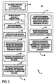
- FIG. 2 illustrates a block diagram of the functions of an automatic segment resolution program construction according to the techniques of the present invention;
- FIG. 3 illustrates a flow chart illustrating the process flow of the present invention;
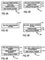
- FIGS. 4A through 4L illustrate command block structures for an automatic segment resolution program embodying the method of the present invention;
- FIG. 5 illustrates a first time line example for the system and method of the present invention; and
- FIG. 6 illustrates a second time line example for the system and method of the present invention.
-
- FIG. 1 illustrates a simplified representation of a typical
computer communications network 10 in which the apparatus, system and method of the present invention for generating operating statistics may be employed. Like reference numerals are employed among the various figures to designate like elements. - More particularly, and with reference to FIG. 1, there is shown a
local area network 10 comprising m segments, a first segment identified by thenumeral 12, a second segment identified by thenumeral 14a, and an mth segment identified by thenumeral 14b. While the present invention may have applications on any network whose segments are transparently bridged to one another, by way of example only, the present invention will be described as implemented on Ethernet. It will be understood by those skilled in the art that the number of segments m is application dependent. Each of thesegments - Attached to the
first segment 12 may be a plurality ofstations 21a. The number ofstations 21a may vary from one to n, the number n being application dependent. Each of thestations 21a may be, for example, a workstation attached using an appropriate Ethernet adaptor board (not shown). Also attached to thisfirst segment 12 is anetwork monitor 20. Thenetwork monitor 20 may be any type of computer and is attached to thenetwork 10 using an appropriate Ethernet adaptor board (not shown). By way of example, thenetwork monitor 20 may be a personal computer which implements the IBM AT bus structure or the IBM microchannel and the Ethernet adaptor board may be a 3Com Model No. 507 (for an AT bus) or No. 523 (for a microchannel). The Ethernet adaptor board must be capable of operating in the promiscuous mode wherein each frame transmitted on thenetwork 10 is read and received by the Ethernet adaptor board. Thenetwork monitor 20 houses the network monitor program, shown functionally in FIG. 2 and further described herein. - In a similar manner, the
second segment 14a hasx stations 25a and asecond network monitor 24a attached thereto, the number x being application dependent. Likewise, the mth segment hasy stations 25b and anmth network monitor 24b attached thereto, the number y being application dependent. In each case, thenetwork monitors segments network monitor - As will be understood by those skilled in the art, the configuration of
segments - As can be seen in FIG. 1, the
first segment 12 and thesecond segment 14a are interconnected viabridge 16. Also, thesecond segment 14a is connected to themth segment 14b viabridge 16. As used herein, abridge 16 is a device which provides the interconnection between segments of alocal area network 10. Thebridge 16, using one of numerous possible algorithms, makes decisions about switching frames between segments based on the address of a station. - The switching algorithms may be transparent to end stations. In an IEEE 802 local area network, the interconnection between
local segments bridge 16 can use a number of different simple algorithms to make its switching decisions. By way of example only, one such algorithm is a "learn as you go" type algorithm in which thebridge 16 maintains a database of thestations segments bridge 16 monitors a message, it knows on which side of thebridge 16 that the message originated and adds that station address and its position relative to thebridge 16 to its database. Thebridge 16, when it picks up a new MAC frame on thenetwork 10, searches that database for the destination address contained in that frame. Forwarding of the frame to the other side of thebridge 16 is based on the results of that search. As such, the simple algorithm requires no effort nor knowledge byend stations bridges 16, so that operation of the bridges is transparent. If the algorithm is similar to the "learn as you go" method as described above, it may be possible that, until steady-state operation is achieved, thebridge 16 may not properly pass all frames, and thus that possibility must be taken into account in the present invention. It is withbridges 16 which operate transparently to endstations - The knowledge that network monitors 20, 24a and 24b are within a transparently bridged group is preferable and aids in the operation of the automated segment resolution of the present invention. Each of those network monitors 20, 24a, 24b are referred to as transparent partners and each network monitor 20, 24a, and 24b preferably maintains a current list of its transparent partners. A unique bit may indicate that a particular network monitor is within a transparently bridged group.
- To detect other network monitors, a bridged group probe message shown as
control block 152 in FIG. 4K may be sent periodically.Control block 152 includes acommand code field 154 and a request/response indicator field 156. Any other network monitor 20, 24a and 24b which sees the bridge group probe message control block 152 will respond with asimilar control block 152 with the response bit set infield 156. To maintain current status, the bridge group probe message is preferably sent periodically. To prevent disturbing other stations on the network, the destination address of that packet may, for example, be the universally administered address ("UAA") of an Ethernet board. The Ethertype of the packet will be a unique non-routable value assigned to the implementor for this purpose. - A host based network monitor (not shown), in communication with the local are
network 10, will preferably receive a report periodically of transparently bridge groups.Control block 158 in FIG. 4L shows an example of such a reporting mechanism comprising acommand code field 160, number of partners field 161 and thenetwork monitor field 162. As such, the host based network monitor (not shown) may keep a current status of the local network monitors 20, 24a and 24b on the attachedlocal area network 10. - With reference to FIG. 2, there is shown a functional block diagram 30 of an automatic segment resolution program which forms a portion of the program operating or residing in the
first network monitor 20, thesecond network monitor 24a and themth network monitor 24b. The functional diagram 30 is subdivided into three portions. Thefirst portion 31 is the function performed if one of the network monitors 20, 24a, 24b is serving as the initiator of the request to resolve the location of a station, 21a, 25a, 25b. Thesecond portion 32 comprises the functions performed if the network monitor 20 is operating as the primary resolver. Thethird portion 46 comprises the functions performed when the network monitor 20 is not the primary resolver but is part of the transparently bridged group. - The processing flow of one implementation of the automated segment resolution program will now be described with reference to the flowchart illustrated in FIG. 3, and with further reference to the functional block diagram 30 in FIG. 2 and the control blocks found in FIGs. 4A through 4L. For the purposes of this description, the network monitor 20 will be the primary resolver and the
other network monitors - The processing flow starts when a
network monitor 20 is requested to resolve ownership of a particular station. That request may come from a host based network monitor (not shown). Such a request may be in the form as shown in FIG. 4E in control block 110 comprising a request code set to resolve station segment infield 112, a primary resolution request indicated infield 114, and the station address infield 116 representing the particular station to be resolved. Alternatively, that request may be generated internally by primary resolver network monitor 20 or be sent from anothernetwork monitor block 31 in FIG. 2. - With reference to FIG. 3, the
first network monitor 20 will request primary resolution atstep 61. The primary resolver network monitor 20 will call the "generating and sending a primary probe"function 34 to generate and send a probe message to the station to be resolved.control block 122 in FIG. 4G may be used to perform thefunction 34. Thecontrol block 122 comprises arequest code field 124 set equal to station segment probe and aprobe type field 126 set to primary. - Once the primary resolver network monitor 20 sends the probes at
step 61, the primary resolver network monitor 20 awaits for a predetermined time period, for example one minute, for responses from that probe message. Responses will be generated by the function identified asblock 47 in FIG. 2 and may take the form ofcontrol block 128 in FIG. 4H. Thecontrol block 128 representing a primary observation report comprises arequest code 130 indicating the probe was observed, a designation of theprobe type 132 set to primary, and the node oraddress field 134 of the station whose ownership is being resolved. Only those network monitors 24a, 24b which actually read the primary probe on theirsegment control block 122 does not appear on alocal segment control block 122 was not transmitted by the attachedbridge 16, the network monitors 24a, 24b do not see thecontrol block 122 and thus cannot respond with a primary observation report. - Referring again to FIG. 3, at
step 62, a decision block as to whether any observations of the primary probe were received is encountered by the primary resolver, in this case, network monitor 20. The network monitor 20 contains afunction 36 shown in FIG. 2 for receiving primary observation reports. If primary observation reports represented bycontrol block 128 were received by the primary resolver network monitor 20, processing continues atstep 66. Atstep 66 the primary resolver network monitor 20 generates and sends secondary probe requests, illustrated functionally atblock 38 in FIG. 2. The secondary probe requests may take the form ofcontrol block 110 shown in FIG. 4E, and described above, with a designation that the target station is a secondary resolver infield 114.Control block 110 is sent to each of the network monitors 24a, 24b which transmitted primary observation reports viacontrol block 128 to the primary resolver network monitor 20, such network monitors being termed secondary resolvers. - Upon receipt of the secondary probe requests, the secondary resolvers send a secondary probe which may be represented as shown in FIG. 4G by
control block 122 withfield 126 set to secondary. The generation of a secondary probe is represented by the function indicated inblock 48 of FIG. 2. - Similar to the primary resolver network monitor 20, each of the secondary resolvers will wait a predetermined time period, for example one minute, for receiving secondary observation reports. Such secondary observation reports may take the form of
control block 128 as described above with theprobe type field 132 set to secondary and will be sent to any network monitor, including the primary resolver network monitor 20, which reads the message on its local segment.Function block 40 in FIG. 2 illustrates the "observing secondary probes and generating secondary observation reports" function. - Each secondary resolver will create a summary of the secondary observation reports it receives and transmit that summary to the primary resolver network monitor 20. Such a summary of secondary probe results, represented functionally by
block 49 in FIG. 2, may be transmitted to the primary resolver network monitor 20 in the form ofcontrol block 136 shown in FIG. 4I.Control block 136 comprises arequest code field 138 and probe result 140 which together indicate that control block 136 contains the summary of secondary observation reports.Control block 136 also includes afield 142 indicating the number of observers of the secondary probe, and anaddress field 144 containing the station address which received the secondary probe. -
Function block 42 in FIG. 2 illustrates the function of the primary resolver which receives the summaries in the form of control block 136 from the secondary resolvers.Function block 44 illustrates the resolving function as performed by the primary resolver network monitor 20. Atstep 68 in FIG. 3, there is a decision made by the primary resolver network monitor 20 as to whether one of the secondary resolvers received no secondary observation reports. If one and only one of the secondary resolvers reports no secondary observations in response to its secondary probe, then that secondary resolver is the owner of the station which was probed. Atstep 70, a station ownership indication is sent to that secondary resolver which may be in the form ofcontrol block 146 in FIG. 4J comprising thestation owner field 148 and anaddress field 150 containing the station that was probed. - If it is determined at
step 68 that none of the secondary resolvers reported no secondary observations or more than one secondary resolver reported no secondary observations, then the primaryresolver network station 20 is unable to resolve station ownership as shown atstep 78. The inability to resolve station ownership is then transmitted to the host network monitor (not shown) or to the initiator of the resolution request from the primary resolver network monitor 20 which message may, for example, be represented bycontrol block 118 in FIG. 4F.Control block 118 contains arequest code field 119 signifying that the primary resolver cannot resolve the station segment and anaddress field 120 indicating the address of the station whose ownership cannot be resolved. - Referring again to FIG. 3, if at
decision block 62 the primary resolver network monitor 20 determines that the primary resolver network monitor 20 did not receive any primary probe observations in response to the primary probe, processing continues atdecision block 64. Atdecision block 64, a determination is made as to whether the primary resolver network monitor 20 is part of a transparently bridged group. That information is known to the primary resolver network monitor 20 as it preferably maintains a list of its transparent partners as described above. If atdecision block 64 the primary resolver network monitor 20 determines that it is not part of a transparently bridged group, i.e., it has no transparent partners, then the primary resolver network monitor 20 makes the determination that the station to be resolved is on itslocal segment 12. Thereafter, the primary resolver network monitor 20 reports that the station is up atstep 80 to the initiator of the resolution request. - If at
decision block 64 it is determined that the primary resolver network monitor 20 is part of a transparently bridged group, i.e., it has transparent partners, then processing continues atstep 72. Atstep 72, the primary resolver selects one of its transparent partners and thereafter generates and sends a secondary probe request to the selected transparent partner, such secondary probe request represented bycontrol block 110 in FIG. 4E as described above. - The selected transparent partner thus becomes the secondary resolver and proceeds to send a secondary probe to the station as outlined above. Each of the other network monitors, including the primary resolver network monitor 20, will perform the observing secondary probes and generating secondary observation reports function 40. The secondary resolver will compile the secondary observation reports and transmit those results to the primary resolver network monitor 20 using, for example,
control block 136 in FIG. 4I as described above. - If
control block 136 which is sent to the primary resolver network monitor 20 indicates that no secondary observation reports were received by the secondary resolver, processing proceeds fromdecision block 74 to step 78 as the primary resolver network monitor is unable to resolve station ownership. That result is transmitted to the host based network monitor (not shown) or the initiator of the resolution request using, for example,control block 118 in FIG. 4F as described above. - If
control block 136 which is sent to the primary resolver network monitor 20 indicates that secondary observation reports were received by the secondary resolver, processing proceeds fromdecision block 74 todecision block 76. Atdecision block 76, the primary resolver network monitor 20 checks to see if the primary resolver network monitor 20 generated a secondary observation report. If the primary resolver network monitor 20 generated a secondary observation report, then the primary resolver network monitor 20 is the owner of the station whose ownership is being resolved. That determination is reported to the host based network monitor (not shown) or the initiator of the resolution request atstep 80. - If at
decision block 76 it is determined that the primary resolver network monitor 20 did not generate a secondary observation report, then the primary resolver network monitor 20 is unable to resolve station ownership as shown atstep 78. It will be understood that any network monitor, 20, 24a, 24b may serve as the primary resolver network monitor. Each of those network monitors 20, 24a, and 24b is preferably in communication with a host based network monitor (not shown) which initiates resolution requests and receives responses thereto. Such host based network monitor communications are ancillary to the present invention and are described herein for completeness. - FIGs. 4A through 4D illustrate control blocks 82, 92, 100, 102, respectively, which may be used for communications between the
network monitor control block 102.Control block 82 andcontrol block 92 may be sent from the host based network monitor to the network monitors 20, 24a, 24b to update the station ownership tables in each network monitor 20, 24a, 24b. The method of operation of the present invention is illustrated by two examples, shown in FIGs. 5 and 6, for a network configuration similar to that shown in FIG. 1. FIG. 5 is an example of station segment resolution wherein the station whose ownership to be resolved does not reside on the primary resolver's local segment. FIG. 6 is an example of station segment resolution wherein the station whose ownership to be resolved resides on the primary resolver's local segment. - With reference to FIG. 5, there is shown message traffic between a host based
network monitor program 172, a plurality of network monitor programs forming a system of transparently bridged monitors represented bynumerals station 180 whose ownership is to be resolved. FIG. 5 message traffic is shown in chronological order with the earlier messages at the top and the later messages at the bottom. A first segment monitor 174 reports to the host basednetwork monitor program 172 thatstation 180 is unassigned. In response thereto, the host basednetwork monitor program 172 requests that the first segment network monitor 174 perform resolution for thatstation 180. The first segment network monitor sends a primary probe tostation 180. The second and third segment network monitors 174, 176, respectively, report that the primary probe was observed. Thereafter, the first segment network monitor 174 sends a secondary probe request to the second and third segment network monitors 174, 176, respectively. The second segment network monitor 176 sends a secondary probe to station 180 and receives a secondary observation report from the third segment network monitor 178 in response thereto. The third segment network monitor 178 sends a secondary probe to station 180 and does not receive any secondary observation reports in response thereto. The second segment network monitor 176 reports to the first segment network monitor 174 that one secondary observation report was received. The third segment network monitor 178 reports to the first segment network monitor 174 that no secondary observation report was received. The firstsegment network monitor 174, after determining thatstation 180 is owned by the thirdsegment network monitor 178, then sends a station ownership indication to the thirdsegment network monitor 178, followed by a station up report from the third segment network monitor 178 to the host basednetwork monitor program 172. - With reference to FIG. 6, there is shown message traffic between a host based
network monitor program 182, a plurality of network monitor programs forming a system of transparently bridged monitors represented bynumerals station 190 whose ownership is to be resolved. Similar to the above description, FIG. 6 message traffic is shown in chronological order with the earlier messages at the top and the later messages at the bottom. A first segment monitor 184 reports to the host basednetwork monitor program 182 thatstation 190 is unassigned. In response thereto, the host basednetwork monitor program 182 requests that the first segment network monitor 184 perform resolution for thatstation 190. The first segment network monitor sends a primary probe tostation 190. Neither the second nor the third segment network monitors 186, 188, respectively, report that the primary probe was observed. Thereafter, the first segment network monitor 184 selects the thirdsegment network monitor 188 and sends a secondary probe request thereto. The third segment network monitor 188 sends a secondary probe to station 190 and receives a secondary observation report from both the first and second network monitors 184, 186, respectively. Third segment network monitor 188 reports to the first segment network monitor 184 that two secondary observation reports were received, including one from the firstsegment network monitor 184. The firstsegment network monitor 184, after determining thatstation 190 resides on the first segment, then sends a station up report to the host basednetwork monitor program 182. - While the present invention has been described in connection with an exemplary embodiment thereof, it will be understood that many modifications and variations will be readily apparent to those of ordinary skill in the art. This disclosure and the following claims are intended to cover all such modifications and variations.
Claims (6)
- A method for resolving ownership of a station (21a, 25a, 25b) on a network (10), wherein said network (10) has a plurality of segments (12, 14a, 14b), each segment (12, 14a, 14b) connected to at least one other segment (12, 14a, 14b) by a bridge (16) operating transparently to the stations (21a, 25a, 25b), wherein each of the segments (12, 14a, 14b) has a network monitor (20, 24a, 24b) attached-thereto, and wherein one of the network monitors (20, 24a, 24b) is a primary resolver network monitor and the other network monitors (20, 24a, 24b) are secondary resolver network monitors, wherein said ownership of said station includes an indication of said segment (12, 14a, 14b) to which said station (21a, 25a, 25b) is connected, said method characterized by the steps of:sending a primary probe message (122) from said primary resolver network monitor to at least one of said segments (12, 14a, 14b) having connected thereto at least one of said stations, wherein one of said stations is a station to be resolved;reading, for each of said segments.(12, 14a, 14b), any responses to the primary probe message (122) received from said stations connected to said segments (12, 14a, 14b), wherein said reading is performed by said secondary resolver network monitor connected to said segment;reporting primary observations (128) of said primary probe message (122) to said primary resolver network monitor, wherein the reporting is performed by at least one of the secondary resolver network monitors, wherein the primary observations (128) each include a control block including an address for at least one of said stations (21a, 25a, 25b);initiating at least one secondary probe request (152) to those said secondary resolver network monitors which reported the primary observations (128), wherein the initiating is performed by the primary resolver network monitor;in response to said initiating step, sending at least one secondary probe message (122) to said stations (21a, 25a, 25b) connected to those said secondary resolver network monitors which reported the primary observations (128), wherein the sending is performed by said secondary resolver network monitors which reported the primary observations (128);reporting secondary observations (128) of said secondary probe message (122) in response to said secondary probe message (122), wherein the reporting is performed by those secondary resolver network monitors which reported the primary observations (128), and wherein the secondary observations (128) each include a control block having an address for at least one of the stations and an indication that the secondary probe message (122) was observed;generating a summary of the secondary observations (136), wherein the generating is performed by those secondary resolver network monitors which reported the primary observations (128), and wherein the summary of the secondary observations (136) includes an address for each of said stations (21a, 25a, 25b) wherein one of said stations is said station to be resolved, and a number indicating how many stations observed the secondary probe message (122); andresolving ownership of said station to be resolved in response to said primary observations (128) and said summary of the secondary observations (136).
- The method of claim 1 wherein said step of resolving station ownership determines ownership to be a primary observer circuit (47) which observes said primary probe (122) but does not observe each of said secondary probe messages (122).
- The method of claim 1 wherein no primary probe messages (122) are observed and wherein said initiating step is directed to a first primary observer circuit (47) and wherein said secondary probe message (122) is observed by a second primary observer circuit (47) and said resolving step determines said second primary observer circuit (47) to be owner of said station (21a, 25a, 25b).
- A system for resolving the location of a station (21a, 25a, 25b) on a network (10), wherein said network (10) comprises a plurality of segments (12, 14a, 14b), each segment (12, 14a, 14b) connected to at least one other segment (12, 14a, 14b) by a bridge (16) operating transparently to the stations (21a, 25a, 25b), each of said segments (12, 14a, 14b) has a network monitor (20, 24a, 24b) attached thereto, and wherein one of said network monitors (20, 24a, 24b) has a primary resolution circuit (32), wherein said ownership of said station includes an indication of said segment to which said station is connected, each of said network monitors (20, 24a, 24b) characterized by:a circuit (34, 48) for sending and receiving primary (122) and secondary probe messages (122) to/from said segments (12, 14a, 14b) each having connected thereto at least one station, wherein one of said stations (21a, 25a, 25b) is a station to be resolved;a circuit for reporting primary observations (47) of said primary probe messages (122) by creating a primary observation report(128) responsive to said primary probe messages (122), wherein the primary observation report (128) includes a control block having an address of at least one of said stations (21a, 25a, 25b);a circuit for reporting secondary observations (40) of said secondary probe messages (122) by creating a secondary observation report (128) responsive to said secondary probe messages (122), wherein the secondary observation report (128) includes a control block having an address of said station (21a, 25a, 25b) to be resolved and includes an indication that the secondary probe messages (122) were observed;a circuit (40) for receiving said primary observation reports (128) and said secondary observation reports (128);a circuit (38) for requesting a secondary probe message (122) responsive to said primary observation reports (128);a circuit (42), responsive to said circuit (40) for receiving said secondary observation report (128), for creating and transmitting a summary (136) of received secondary observation reports (128), wherein the summary (136) of the secondary observation reports includes an address of the station (21a, 25a, 25b) to be resolved and a number indicating how many stations observed the secondary probe message (122); anda circuit (44) for resolving ownership of said station (21a, 25a, 25b) to be resolved based on said primary observation reports (128) and said summaries (136).
- The system of claim 4 wherein at least one primary observing circuit (47) observes said primary probe messages (122) and wherein said secondary probe requests (152) are directed to each of said primary observing circuits (47) which observe said primary probe messages (122); and whereby said circuit (44) for resolving resolves station ownership to be said primary observing circuit (47) which observes said primary probe messages (122) but does not observe each of said secondary probe messages (122).
- The system of claim 4 wherein no primary observing circuits (47) observe said primary probe messages (122) and wherein a secondary probe request (152) is directed to one of said primary observing circuits (47) and said secondary probe (122) is observed by said primary resolution circuit (32); and whereby said resolving circuit (44) resolves said primary resolution circuit (32) to be owner of said station (21a, 25a, 25b).
Applications Claiming Priority (3)
| Application Number | Priority Date | Filing Date | Title |
|---|---|---|---|
| US21786 | 1993-02-24 | ||
| US08/021,786 US5437046A (en) | 1993-02-24 | 1993-02-24 | System and method for resolving the location of a station on a local area network |
| PCT/US1994/002030 WO1994019889A1 (en) | 1993-02-24 | 1994-02-24 | System and method for automatic segment resolution on a local area network |
Publications (2)
| Publication Number | Publication Date |
|---|---|
| EP0637415A1 EP0637415A1 (en) | 1995-02-08 |
| EP0637415B1 true EP0637415B1 (en) | 2003-07-02 |
Family
ID=21806139
Family Applications (1)
| Application Number | Title | Priority Date | Filing Date |
|---|---|---|---|
| EP94910176A Expired - Lifetime EP0637415B1 (en) | 1993-02-24 | 1994-02-24 | System and method for automatic segment resolution on a local area network |
Country Status (8)
| Country | Link |
|---|---|
| US (1) | US5437046A (en) |
| EP (1) | EP0637415B1 (en) |
| JP (1) | JP3378008B2 (en) |
| AT (1) | ATE244480T1 (en) |
| AU (1) | AU678219B2 (en) |
| DE (1) | DE69432883T2 (en) |
| ES (1) | ES2201073T3 (en) |
| WO (1) | WO1994019889A1 (en) |
Families Citing this family (27)
| Publication number | Priority date | Publication date | Assignee | Title |
|---|---|---|---|---|
| GB2272310A (en) * | 1992-11-07 | 1994-05-11 | Ibm | Method of operating a computer in a network. |
| JPH08235006A (en) * | 1995-02-24 | 1996-09-13 | Fujitsu Ltd | Condition monitoring system |
| US5793974A (en) * | 1995-06-30 | 1998-08-11 | Sun Microsystems, Inc. | Network navigation and viewing system for network management system |
| CA2190433A1 (en) * | 1995-11-16 | 1997-05-17 | Nicholas W. Dawes | Method of determining the topology of a network of objects |
| US5926462A (en) * | 1995-11-16 | 1999-07-20 | Loran Network Systems, Llc | Method of determining topology of a network of objects which compares the similarity of the traffic sequences/volumes of a pair of devices |
| US5805818A (en) * | 1996-09-11 | 1998-09-08 | Novell, Inc. | System for acknowledging availability of neighbor node using data packet containing data that is ordinarily fowarded to neighbor node |
| US5886643A (en) * | 1996-09-17 | 1999-03-23 | Concord Communications Incorporated | Method and apparatus for discovering network topology |
| US6112237A (en) * | 1996-11-26 | 2000-08-29 | Global Maintech, Inc. | Electronic monitoring system and method for externally monitoring processes in a computer system |
| US6044393A (en) * | 1996-11-26 | 2000-03-28 | Global Maintech, Inc. | Electronic control system and method for externally and directly controlling processes in a computer system |
| US6157956A (en) * | 1997-03-28 | 2000-12-05 | Global Maintech, Inc. | Heterogeneous computing interface apparatus and method using a universal character set |
| SE513246C2 (en) * | 1997-06-23 | 2000-08-07 | Ericsson Telefon Ab L M | Procedure and device in an IP-based network |
| US6519671B1 (en) * | 1998-01-23 | 2003-02-11 | Sony Corporation | Method of network configuration, method and apparatus for information processing, and computer-readable media |
| AU2612501A (en) * | 1999-12-30 | 2001-07-16 | Computer Associates Think, Inc. | System and method for device failure recognition |
| US7167470B2 (en) * | 2001-03-15 | 2007-01-23 | American Express Travel Related Services Company, Inc. | Method and apparatus for locating a communication device using local area network switch information |
| US7376734B2 (en) * | 2002-02-14 | 2008-05-20 | Panduit Corp. | VOIP telephone location system |
| US7519000B2 (en) * | 2002-01-30 | 2009-04-14 | Panduit Corp. | Systems and methods for managing a network |
| US20050141431A1 (en) * | 2003-08-06 | 2005-06-30 | Caveney Jack E. | Network managed device installation and provisioning technique |
| US7444396B2 (en) * | 2003-08-29 | 2008-10-28 | Sun Microsystems, Inc. | Transferring system identities |
| US20050111491A1 (en) * | 2003-10-23 | 2005-05-26 | Panduit Corporation | System to guide and monitor the installation and revision of network cabling of an active jack network |
| US7207846B2 (en) * | 2003-11-24 | 2007-04-24 | Panduit Corp. | Patch panel with a motherboard for connecting communication jacks |
| US7455527B2 (en) | 2004-05-03 | 2008-11-25 | Panduit Corp. | Powered patch panel |
| US7986639B1 (en) | 2004-10-26 | 2011-07-26 | Sprint Communications Company L.P. | Topology management of a communications network |
| US8015278B1 (en) * | 2004-10-26 | 2011-09-06 | Sprint Communications Company L.P. | Automating alarm handling in a communications network using network-generated tickets and customer-generated tickets |
| US7796500B1 (en) | 2004-10-26 | 2010-09-14 | Sprint Communications Company L.P. | Automated determination of service impacting events in a communications network |
| US20060262087A1 (en) * | 2005-05-23 | 2006-11-23 | Xerox Corporation | Unified status support over USB and HTTP |
| US8514884B2 (en) | 2008-05-14 | 2013-08-20 | Dell Products L.P. | Upper layer protocol selection |
| US10020994B2 (en) * | 2014-04-15 | 2018-07-10 | Virtual Instruments Corporation | Automatically determining locations of network monitors in a communication network |
Family Cites Families (5)
| Publication number | Priority date | Publication date | Assignee | Title |
|---|---|---|---|---|
| JPS6170654A (en) * | 1984-09-14 | 1986-04-11 | Hitachi Ltd | Resource management method in distributed processing system |
| US4817080A (en) * | 1987-02-24 | 1989-03-28 | Digital Equipment Corporation | Distributed local-area-network monitoring system |
| US4799211A (en) * | 1987-07-23 | 1989-01-17 | Digital Equipment Corporation | Apparatus and method for storing performance parameters of local area network system members |
| JP3315404B2 (en) * | 1990-09-28 | 2002-08-19 | ヒューレット・パッカード・カンパニー | How to detect network topological features |
| US5179554A (en) * | 1991-04-08 | 1993-01-12 | Digital Equipment Corporation | Automatic association of local area network station addresses with a repeater port |
-
1993
- 1993-02-24 US US08/021,786 patent/US5437046A/en not_active Expired - Lifetime
-
1994
- 1994-02-24 AU AU62721/94A patent/AU678219B2/en not_active Ceased
- 1994-02-24 JP JP51928194A patent/JP3378008B2/en not_active Expired - Fee Related
- 1994-02-24 DE DE69432883T patent/DE69432883T2/en not_active Expired - Lifetime
- 1994-02-24 ES ES94910176T patent/ES2201073T3/en not_active Expired - Lifetime
- 1994-02-24 AT AT94910176T patent/ATE244480T1/en not_active IP Right Cessation
- 1994-02-24 WO PCT/US1994/002030 patent/WO1994019889A1/en not_active Ceased
- 1994-02-24 EP EP94910176A patent/EP0637415B1/en not_active Expired - Lifetime
Also Published As
| Publication number | Publication date |
|---|---|
| JPH07507671A (en) | 1995-08-24 |
| US5437046A (en) | 1995-07-25 |
| WO1994019889A1 (en) | 1994-09-01 |
| ATE244480T1 (en) | 2003-07-15 |
| EP0637415A1 (en) | 1995-02-08 |
| AU678219B2 (en) | 1997-05-22 |
| AU6272194A (en) | 1994-09-14 |
| JP3378008B2 (en) | 2003-02-17 |
| DE69432883D1 (en) | 2003-08-07 |
| ES2201073T3 (en) | 2004-03-16 |
| DE69432883T2 (en) | 2004-05-27 |
Similar Documents
| Publication | Publication Date | Title |
|---|---|---|
| US5437046A (en) | System and method for resolving the location of a station on a local area network | |
| US9998337B2 (en) | Identifying nodes in a ring network | |
| US6324577B1 (en) | Network management system for managing states of nodes | |
| US7548540B2 (en) | Dynamic discovery of ISO layer-2 topology | |
| US5675741A (en) | Method and apparatus for determining a communications path between two nodes in an Internet Protocol (IP) network | |
| US6594227B1 (en) | Communication control system | |
| JP4707288B2 (en) | Network monitoring apparatus and network monitoring method | |
| US7660262B2 (en) | Network management method and communications network system | |
| US20020032761A1 (en) | Method of automatically recognizing network configuration including intelligent packet relay equipment, method of displaying network configuration chart, and system thereof | |
| US6421317B1 (en) | Method and apparatus for an automatic load balancing and back-up of a multi-users network | |
| EP1185041A2 (en) | OSPF autonomous system with a backbone divided into two sub-areas | |
| EP1222724B1 (en) | Method and apparatus for failure detection in a communications network | |
| US7626937B2 (en) | System and method for network connection detection | |
| US7245618B2 (en) | Communication device for automatically setting a router configuration and method of controlling the device | |
| JP2005237018A (en) | Data transmission to network management system | |
| US7352773B2 (en) | Relay apparatus and network relay method | |
| JP2684985B2 (en) | Server / client virtual communication method | |
| JP3209620B2 (en) | Communications system | |
| GB2361140A (en) | Network management apparatus and method for identifying changes in addresses of devices on a network | |
| JPH1117679A (en) | Network monitoring system | |
| JPH06120950A (en) | Network connection device | |
| JPS63139443A (en) | Communication network diagnosis system |
Legal Events
| Date | Code | Title | Description |
|---|---|---|---|
| PUAI | Public reference made under article 153(3) epc to a published international application that has entered the european phase |
Free format text: ORIGINAL CODE: 0009012 |
|
| 17P | Request for examination filed |
Effective date: 19941122 |
|
| AK | Designated contracting states |
Kind code of ref document: A1 Designated state(s): AT BE CH DE DK ES FR GB GR IE IT LI LU MC NL PT SE |
|
| 17Q | First examination report despatched |
Effective date: 19990420 |
|
| GRAH | Despatch of communication of intention to grant a patent |
Free format text: ORIGINAL CODE: EPIDOS IGRA |
|
| GRAH | Despatch of communication of intention to grant a patent |
Free format text: ORIGINAL CODE: EPIDOS IGRA |
|
| RAP1 | Party data changed (applicant data changed or rights of an application transferred) |
Owner name: COMPUTER ASSOCIATES THINK, INC. |
|
| GRAA | (expected) grant |
Free format text: ORIGINAL CODE: 0009210 |
|
| AK | Designated contracting states |
Designated state(s): AT BE CH DE DK ES FR GB GR IE IT LI LU MC NL PT SE |
|
| PG25 | Lapsed in a contracting state [announced via postgrant information from national office to epo] |
Ref country code: NL Free format text: LAPSE BECAUSE OF FAILURE TO SUBMIT A TRANSLATION OF THE DESCRIPTION OR TO PAY THE FEE WITHIN THE PRESCRIBED TIME-LIMIT Effective date: 20030702 Ref country code: LI Free format text: LAPSE BECAUSE OF FAILURE TO SUBMIT A TRANSLATION OF THE DESCRIPTION OR TO PAY THE FEE WITHIN THE PRESCRIBED TIME-LIMIT Effective date: 20030702 Ref country code: CH Free format text: LAPSE BECAUSE OF FAILURE TO SUBMIT A TRANSLATION OF THE DESCRIPTION OR TO PAY THE FEE WITHIN THE PRESCRIBED TIME-LIMIT Effective date: 20030702 Ref country code: BE Free format text: LAPSE BECAUSE OF FAILURE TO SUBMIT A TRANSLATION OF THE DESCRIPTION OR TO PAY THE FEE WITHIN THE PRESCRIBED TIME-LIMIT Effective date: 20030702 Ref country code: AT Free format text: LAPSE BECAUSE OF FAILURE TO SUBMIT A TRANSLATION OF THE DESCRIPTION OR TO PAY THE FEE WITHIN THE PRESCRIBED TIME-LIMIT Effective date: 20030702 |
|
| REG | Reference to a national code |
Ref country code: GB Ref legal event code: FG4D |
|
| REG | Reference to a national code |
Ref country code: CH Ref legal event code: EP |
|
| REG | Reference to a national code |
Ref country code: IE Ref legal event code: FG4D |
|
| REF | Corresponds to: |
Ref document number: 69432883 Country of ref document: DE Date of ref document: 20030807 Kind code of ref document: P |
|
| PG25 | Lapsed in a contracting state [announced via postgrant information from national office to epo] |
Ref country code: SE Free format text: LAPSE BECAUSE OF FAILURE TO SUBMIT A TRANSLATION OF THE DESCRIPTION OR TO PAY THE FEE WITHIN THE PRESCRIBED TIME-LIMIT Effective date: 20031002 Ref country code: PT Free format text: LAPSE BECAUSE OF FAILURE TO SUBMIT A TRANSLATION OF THE DESCRIPTION OR TO PAY THE FEE WITHIN THE PRESCRIBED TIME-LIMIT Effective date: 20031002 Ref country code: GR Free format text: LAPSE BECAUSE OF FAILURE TO SUBMIT A TRANSLATION OF THE DESCRIPTION OR TO PAY THE FEE WITHIN THE PRESCRIBED TIME-LIMIT Effective date: 20031002 Ref country code: DK Free format text: LAPSE BECAUSE OF FAILURE TO SUBMIT A TRANSLATION OF THE DESCRIPTION OR TO PAY THE FEE WITHIN THE PRESCRIBED TIME-LIMIT Effective date: 20031002 |
|
| NLV1 | Nl: lapsed or annulled due to failure to fulfill the requirements of art. 29p and 29m of the patents act | ||
| REG | Reference to a national code |
Ref country code: CH Ref legal event code: PL |
|
| PG25 | Lapsed in a contracting state [announced via postgrant information from national office to epo] |
Ref country code: LU Free format text: LAPSE BECAUSE OF NON-PAYMENT OF DUE FEES Effective date: 20040224 |
|
| PG25 | Lapsed in a contracting state [announced via postgrant information from national office to epo] |
Ref country code: MC Free format text: LAPSE BECAUSE OF NON-PAYMENT OF DUE FEES Effective date: 20040228 |
|
| REG | Reference to a national code |
Ref country code: ES Ref legal event code: FG2A Ref document number: 2201073 Country of ref document: ES Kind code of ref document: T3 |
|
| PLBE | No opposition filed within time limit |
Free format text: ORIGINAL CODE: 0009261 |
|
| STAA | Information on the status of an ep patent application or granted ep patent |
Free format text: STATUS: NO OPPOSITION FILED WITHIN TIME LIMIT |
|
| ET | Fr: translation filed | ||
| 26N | No opposition filed |
Effective date: 20040405 |
|
| PGFP | Annual fee paid to national office [announced via postgrant information from national office to epo] |
Ref country code: IE Payment date: 20050118 Year of fee payment: 12 |
|
| PG25 | Lapsed in a contracting state [announced via postgrant information from national office to epo] |
Ref country code: IT Free format text: LAPSE BECAUSE OF NON-PAYMENT OF DUE FEES;WARNING: LAPSES OF ITALIAN PATENTS WITH EFFECTIVE DATE BEFORE 2007 MAY HAVE OCCURRED AT ANY TIME BEFORE 2007. THE CORRECT EFFECTIVE DATE MAY BE DIFFERENT FROM THE ONE RECORDED. Effective date: 20050224 |
|
| PG25 | Lapsed in a contracting state [announced via postgrant information from national office to epo] |
Ref country code: IE Free format text: LAPSE BECAUSE OF NON-PAYMENT OF DUE FEES Effective date: 20060224 |
|
| REG | Reference to a national code |
Ref country code: IE Ref legal event code: MM4A |
|
| PGFP | Annual fee paid to national office [announced via postgrant information from national office to epo] |
Ref country code: ES Payment date: 20080324 Year of fee payment: 15 |
|
| PGRI | Patent reinstated in contracting state [announced from national office to epo] |
Ref country code: IT Effective date: 20080301 |
|
| PGFP | Annual fee paid to national office [announced via postgrant information from national office to epo] |
Ref country code: IT Payment date: 20080226 Year of fee payment: 15 Ref country code: GB Payment date: 20080220 Year of fee payment: 15 |
|
| PGFP | Annual fee paid to national office [announced via postgrant information from national office to epo] |
Ref country code: FR Payment date: 20080208 Year of fee payment: 15 |
|
| GBPC | Gb: european patent ceased through non-payment of renewal fee |
Effective date: 20090224 |
|
| REG | Reference to a national code |
Ref country code: FR Ref legal event code: ST Effective date: 20091030 |
|
| REG | Reference to a national code |
Ref country code: ES Ref legal event code: FD2A Effective date: 20090225 |
|
| PG25 | Lapsed in a contracting state [announced via postgrant information from national office to epo] |
Ref country code: GB Free format text: LAPSE BECAUSE OF NON-PAYMENT OF DUE FEES Effective date: 20090224 Ref country code: FR Free format text: LAPSE BECAUSE OF NON-PAYMENT OF DUE FEES Effective date: 20090302 |
|
| PG25 | Lapsed in a contracting state [announced via postgrant information from national office to epo] |
Ref country code: ES Free format text: LAPSE BECAUSE OF NON-PAYMENT OF DUE FEES Effective date: 20090225 |
|
| PG25 | Lapsed in a contracting state [announced via postgrant information from national office to epo] |
Ref country code: IT Free format text: LAPSE BECAUSE OF NON-PAYMENT OF DUE FEES Effective date: 20090224 |
|
| PGFP | Annual fee paid to national office [announced via postgrant information from national office to epo] |
Ref country code: DE Payment date: 20130220 Year of fee payment: 20 |
|
| REG | Reference to a national code |
Ref country code: DE Ref legal event code: R071 Ref document number: 69432883 Country of ref document: DE |
|
| PG25 | Lapsed in a contracting state [announced via postgrant information from national office to epo] |
Ref country code: DE Free format text: LAPSE BECAUSE OF EXPIRATION OF PROTECTION Effective date: 20140225 |