EP0637358B1 - Lost motion actuator - Google Patents
Lost motion actuator Download PDFInfo
- Publication number
- EP0637358B1 EP0637358B1 EP93908362A EP93908362A EP0637358B1 EP 0637358 B1 EP0637358 B1 EP 0637358B1 EP 93908362 A EP93908362 A EP 93908362A EP 93908362 A EP93908362 A EP 93908362A EP 0637358 B1 EP0637358 B1 EP 0637358B1
- Authority
- EP
- European Patent Office
- Prior art keywords
- orifice
- upper piston
- chamber
- actuator
- piston
- Prior art date
- Legal status (The legal status is an assumption and is not a legal conclusion. Google has not performed a legal analysis and makes no representation as to the accuracy of the status listed.)
- Expired - Lifetime
Links
Images
Classifications
-
- F—MECHANICAL ENGINEERING; LIGHTING; HEATING; WEAPONS; BLASTING
- F01—MACHINES OR ENGINES IN GENERAL; ENGINE PLANTS IN GENERAL; STEAM ENGINES
- F01L—CYCLICALLY OPERATING VALVES FOR MACHINES OR ENGINES
- F01L13/00—Modifications of valve-gear to facilitate reversing, braking, starting, changing compression ratio, or other specific operations
- F01L13/0015—Modifications of valve-gear to facilitate reversing, braking, starting, changing compression ratio, or other specific operations for optimising engine performances by modifying valve lift according to various working parameters, e.g. rotational speed, load, torque
- F01L13/0031—Modifications of valve-gear to facilitate reversing, braking, starting, changing compression ratio, or other specific operations for optimising engine performances by modifying valve lift according to various working parameters, e.g. rotational speed, load, torque by modification of tappet or pushrod length
-
- F—MECHANICAL ENGINEERING; LIGHTING; HEATING; WEAPONS; BLASTING
- F01—MACHINES OR ENGINES IN GENERAL; ENGINE PLANTS IN GENERAL; STEAM ENGINES
- F01L—CYCLICALLY OPERATING VALVES FOR MACHINES OR ENGINES
- F01L1/00—Valve-gear or valve arrangements, e.g. lift-valve gear
- F01L1/12—Transmitting gear between valve drive and valve
- F01L1/14—Tappets; Push rods
- F01L1/16—Silencing impact; Reducing wear
-
- F—MECHANICAL ENGINEERING; LIGHTING; HEATING; WEAPONS; BLASTING
- F01—MACHINES OR ENGINES IN GENERAL; ENGINE PLANTS IN GENERAL; STEAM ENGINES
- F01L—CYCLICALLY OPERATING VALVES FOR MACHINES OR ENGINES
- F01L1/00—Valve-gear or valve arrangements, e.g. lift-valve gear
- F01L1/20—Adjusting or compensating clearance
- F01L1/22—Adjusting or compensating clearance automatically, e.g. mechanically
- F01L1/24—Adjusting or compensating clearance automatically, e.g. mechanically by fluid means, e.g. hydraulically
- F01L1/245—Hydraulic tappets
- F01L1/255—Hydraulic tappets between cam and rocker arm
Definitions
- This invention relates to hydraulic actuators such as may be found in internal combustion engines and more particularly to a lost motion actuator for an electronic valve timing system for internal combustion engines.
- ECU electronice control unit
- receives signals from several different sensors in the vehicle such as speed, load, temperature, etc.
- the optimum time to open and close engine valves is calculated.
- the optimum time is converted to an electronic signal, either digital or analog, and supplied to a solenoid operated control valve to control the flow of hydraulic fluid in and out of a hydraulic tappet or valve lifter.
- U.S. Patent 4,615,306 issued to Russell Wakeman and entitled “Engine Valve Timing Control System” describes a basic engine valve control system wherein the opening and closing of the hydraulic valve lifters creates pressure pulses in the hydraulic fluid to provide a boost pulse to move the lifter to its extreme position.
- An electronic control unit controls the operation of the solenoid operated valve to add or remove hydraulic fluid from the lifter to create a fluid link in the lifter transferring motion from the timing cam on the camshaft to the engine valve.
- U.S. Patent 4,223,648 issued to Pozniak et al and entitled “Hydraulic Valve Lifter describes a "leak-down" hydraulic lifter wherein a Belleville spring valve disc having a thin, sharp edge orifice that is operative to sense the oil flow rate between the valve chamber 53 and the reservoir chamber 24 to regulate the volume capacity of the pressure chamber and therefore the axial extent of the valve lifter as a function of engine speed. Actual leakage of the fluid due to the fit between adjacent telescoping parts permits the lifter to collapse as the tappet approaches the high point of the timing cam.
- French patent FR-A-2 484 531 discloses a lost motion hydraulic actuator of an internal combustion engine in a bore in the cylinder head.
- the disclosed actuator has a tubular housing member with a support ring intermediate the ends of the housing for dividing the housing into an upper chamber and a lower chamber.
- a lower piston in contact with the timing cam, is mounted for reciprocal motion in the lower chamber and biased outward of the housing by a first bias spring from the support ring to the lower piston.
- An upper piston is mounted for reciprocal motion in the upper chamber.
- At least one inlet extends through the wall of the housing for receiving hydraulic fluid into the lower chamber.
- the upper piston is biased outward of the housing by means of a second bias spring and the actuator has a fluid communication passageway means intermediate the ends of the housing member between the walls of bore and the outside periphery of the housing member.
- the communication passageway intersects the inlet and controls the flow of hydraulic fluid between the chambers.
- a communication port connects the fluid communication passageway with the upper chamber with the port being opened and closed by the reciprocal motion of the upper piston.
- An orifice disk plate is mounted on the support ring in the upper chamber and biased against the support ring by the second bias spring.
- the disk plate has a plurality of flow ring passages around its periphery for allowing the flow of hydraulic fluid from the lower chamber to the upper chamber when said disk plate is off of the support ring.
- a thin orifice is centrally located in the orifice disk plate for controlling the flow of hydraulic fluid from the upper chamber to the lower chamber when the upper piston closes the communication port to provide damping of the upper piston during the reciprocal movement of the upper piston toward its normal position.
- the upper piston in its normal position, when the engine valve is closed, is located against a shoulder located in the upper chamber. Said shoulder limits the movement of said disk plate when the fluid flows from the lower chamber to the upper chamber
- the actuator 14 is mounted in a bore 16 in the cylinder head 18 of the engine and is contained there by means of fasteners such as bolts, not shown, passing through clearance holes 20 in the actuator 14 and being threaded into the cylinder head 18.
- At least two seal members 22, 24 are located around the outside diameter of the actuator 14 to control or prevent leakage of the hydraulic fluid from between the actuator 14 and the bore 16 and into the various volumes in the cylinder head and the engine.
- the hydraulic fluid in most installations is engine oil. As the temperature of the engine oil changes, from -30°C to +150°, the viscosity of the engine oil varies over a range of three magnitudes (500 Saybolt Universal Seconds, "SUS", to 5 SUS).
- the fluid control of the hydraulic fluid is by means of a solenoid actuated valve 26 controlled by an electronic valve timing control unit or ECU 28.
- the solenoid actuated valve 26 is operated to control the flow of the hydraulic fluid to and from the actuator 14 in a manner as described in United States Patent 4,615,306.
- This is one of several patents describing an electronic valve timing, EVT, system. While an EVT system can not create more valve motion, it can reduce the valve motion created by the timing cam 30.
- the EVT system can be programmed to allow standard or full valve lift, as illustrated in Figure 10, down to zero valve lift in any increment.
- a one-way valve 32 controls the flow of fluid from a pump 34 to the cylinder head 18.
- the solenoid valve 26 when the solenoid valve 26 is opened, the hydraulic fluid flows into the actuator 14 to maintain the proper amount of fluid therein and to maintain the pressure of the fluid.
- the solenoid valve 26 When the solenoid valve 26 is closed, the fluid is trapped in the actuator 14 forming a "solid fluid link" that functions to operate the actuator 14 by having the lower piston 36 solidly connected, by the fluid link, to the upper piston 38 so that both reciprocate together.
- the upper piston 38 is operatively connected to the engine valve of the engine.
- the engine valve is biased closed by means of a valve spring which also functions to maintain the upper piston 38 in its normal position as will herein be described.
- the solenoid valve 26 when the solenoid valve 26 is opened the hydraulic fluid, under the pressure of the valve spring, not shown, flows back to the oil supply 40.
- the ECU 28 receives various signals from several engine sensors, not shown, and according to predetermined conditions controls the operation of the solenoid actuated valve 26.
- the upper piston 38 is slideably located for reciprocal motion in a by-pass sleeve or tubular housing member 42. In its normal position, the upper piston 38 rests on a shoulder 44 as illustrated in Figure 1.
- the by-pass sleeve 42 in cross-section as indicated in Figure 1, is shaped like an "H" with the upper piston 38 located in an upper chamber 46 above the cross bar of the "H” forming a support ring 54 and the lower piston 36 located in the lower chamber 48 below the cross bar of the "H". Both pistons 36, 38 are located along the vertical axis of the by-pass sleeve 42.
- a second bias or upper spring 50 which biases the upper piston 38 away from the cross bar.
- the upper spring 50 is supported at one end by means of an orifice plate 52 resting on a support ring 54 formed in the cross bar and is located against the bottom of a blind bore in the upper piston 38.
- a chamber passage 56 Located axially in the cross bar, is a chamber passage 56 allowing the flow of fluid between the upper 46 and lower 48 chambers.
- a first bias or lower or tappet spring 58 biasing the lower or tappet piston 36 against the timing cam 30.
- the timing cam 30 is connected to an engine rotating shaft, typically the engine camshaft, and provides the basic valve opening and closing times for the various engine valves. In a typical engine, there is one cam for each valve and there is at least one intake and one exhaust valve per cylinder. Since this operation is well known, the camshaft and engine are not shown.
- Located in and extending through the legs of the "H" shaped by-pass sleeve 42 are at least one inlet means or spaced ports 60 providing passageways for the flow of hydraulic fluid into and out of the lower chamber 48.
- a circumferential communication passageway 62 functioning to provide a passageway for the flow of hydraulic fluid from the solenoid actuated valve 26 to the ports 60 and also providing for the flow of fluid between the upper chamber 46 and the lower chamber 48.
- a communication port 64 Located near the top end of the communication passageway 60 is a communication port 64 connecting the communication passageway 62 to the upper chamber 46. It is the vertical positioning, "D" as shown in Figures 5 and 10, from the end of the communication port 64 to the top of the shoulder 44 in the upper chamber 46 that determines when and where in the valve operation cycle the damping of the lower piston 36 begins. This is further illustrated in Figure 10.
- Figures 2-6 show, respectively, the operation of the lost motion actuator 14.
- Figure 2 illustrates zero lift when the lower piston 36 is riding on the the base circle of the timing cam 30.
- Figures 3-6 the flow of the hydraulic fluid within the actuator 14 is illustrated by dashed lines when the solenoid actuated valve 26 is closed and there is no flow of fluid out of the actuator.
- Figure 3 illustrates the movement of the pistons 36, 38 as the lower piston 36 rides on the rising portion of the timing cam 30 causing the engine valve to begin to open.
- Figure 4 illustrates the movement of the pistons 36, 38 as the lower piston 36 approaches the top of the timing cam 30 and the flow of the hydraulic fluid in the actuator.
- Figure 5 illustrates the movement of the pistons as the tappet leaves the top of the timing cam as the engine valve is beginning to close.
- Figure 6 illustrates the movement of the pistons 36, 38 as the lower piston 36 approaches the base circle of the timing cam 30. Without the provision of a thin sharp edge orifice 66 in the orifice plate 52 and the communication port 64 from the upper chamber 46 to the communication way 62, the actuator 14 movement would be very similar to that illustrated by the dashed lines 68 in Figure 10.
- Figure 9 illustrates the standard lift profile 70 of an engine valve unmodified by EVT. In both Figures 9 and 10, the abscissa is the angle of rotation of the timing camshaft and ordinate is the amount of lift or opening of the engine valve.
- the fluid flows from the lower chamber 48 through the chamber passage 56 and from there in parallel through the orifice 66 and the flow ring passages 72 between the locating lugs 74 on the orifice plate.
- Figures 7 and 8 show in greater detail the flow ring passages 72 and locating lugs 74 on the orifice plate 52.
- the pressure of the fluid being "pumped" by the lower piston 36 causes the orifice plate 52 to lift off of the support ring 54 allowing the fluid to flow from the chamber passage 56 through the flow ring passages 72 between the locating lugs 74 of the orifice plate 52.
- the upper piston 38 has been lifted at least a distance "D" and is clear of the bottom of the communication ports 64 in the by-pass sleeve 42.
- the hydraulic fluid can now flow out of the inlet ports 60, through the communication passageway 62 and into the upper chamber 46.
- This increases the size of the flow routes and therefore increases the amount of fluid flowing from the lower chamber 48 to the upper chamber 46.
- This is an improvement over previous designs of actuators in that the parasitic losses from the actuator are reduced. The result is a faster rise of the upper piston 38 and the hence the opening of the engine valve.
- Figures 5 and 6 illustrate the flow of the hydraulic fluid from the decreasing volume of the upper chamber 46 to the expanding volume of the lower chamber 48 as the engine valve closes.
- the fluid flows both through the orifice 66 and through the communication ports 64 and communication passageway 62.
- the pressure of the fluid causes the orifice plate 52 to seat on the support ring 54 on the cross bar of the by-pass sleeve 42.
- the upper piston 38 begins to close off the communication ports 64, the flow of the fluid lessens and the damping action of the upper piston 38 begins.
- Figure 10 illustrates the relationship of the height "D" of the communication ports 64 above the shoulder 44 and the beginning of the damping slope 78 of the closure of the engine valve.
- FIG. 11 there is illustrated an alternate embodiment of the upper piston 38.
- the leading edge 80 of the upper piston 38 must be relieved by relief means 82 such as a chamfer having an angle "B" and an axial height of "H1".
- the leading edge 80 may be undercut by means of a stepped surface, not shown.
- the relationship between the angle "B” and the axial height "H1" is provide a gradual initiation of the damping function as the upper piston 38 covers the communication ports 64.
- the axial height "H1" on the leading edge 80 of the upper piston 38 is less than the distance "H2", in Figure 1, from the bottom of the communication ports 64 above the shoulder 44 in the by-pass sleeve 42.
- the chamfer 82 allows gradual closing off the fluid flow and hence reduces the pressure pulsations do to abrupt closing the communication ports 64.
- Unwanted pressure pulsations similar to hydraulic hammer when a flow port is closed very rapidly, operate to provide deviations in valve lift.
- the size of the orifice 66 determines the amount of flow of the fluid from the upper chamber 46 to the lower chamber 48 and hence the total time "T" of damping including controlling the slope 78 of the curve of Figure 10 approaching the base circle. It is well known that as the length of the orifice 66, or the thickness of the orifice plate in the area of the orifice, approaches a thin sharp edge, the viscosity term in the equation for determining the flow of the fluid "falls out" of the equation.
- the surface of the orifice plate 52 around the orifice 66 is chamfered to reduce the length of the orifice 66 so as to present a thin sharp edge to the flow of the fluid from the upper chamber 46 to the lower chamber 48.
- the chamfer or bevelled edge is on the surface of orifice disk member 52 facing the lower chamber 48.
Landscapes
- Engineering & Computer Science (AREA)
- Mechanical Engineering (AREA)
- General Engineering & Computer Science (AREA)
- Valve Device For Special Equipments (AREA)
- Valve-Gear Or Valve Arrangements (AREA)
Abstract
Description
- This invention relates to hydraulic actuators such as may be found in internal combustion engines and more particularly to a lost motion actuator for an electronic valve timing system for internal combustion engines.
- One of the many ways to improve engine performance in motor vehicles is by means of electronic controlled valve actuation systems. In these systems, an electronic control unit, ECU, receives signals from several different sensors in the vehicle such as speed, load, temperature, etc., and by means of certain algorithms in the electronic control unit, the optimum time to open and close engine valves is calculated. The optimum time is converted to an electronic signal, either digital or analog, and supplied to a solenoid operated control valve to control the flow of hydraulic fluid in and out of a hydraulic tappet or valve lifter.
- U.S. Patent 4,615,306 issued to Russell Wakeman and entitled "Engine Valve Timing Control System" describes a basic engine valve control system wherein the opening and closing of the hydraulic valve lifters creates pressure pulses in the hydraulic fluid to provide a boost pulse to move the lifter to its extreme position. An electronic control unit controls the operation of the solenoid operated valve to add or remove hydraulic fluid from the lifter to create a fluid link in the lifter transferring motion from the timing cam on the camshaft to the engine valve.
- U.S. Patent 4,223,648 issued to Pozniak et al and entitled "Hydraulic Valve Lifter describes a "leak-down" hydraulic lifter wherein a Belleville spring valve disc having a thin, sharp edge orifice that is operative to sense the oil flow rate between the valve chamber 53 and the
reservoir chamber 24 to regulate the volume capacity of the pressure chamber and therefore the axial extent of the valve lifter as a function of engine speed. Actual leakage of the fluid due to the fit between adjacent telescoping parts permits the lifter to collapse as the tappet approaches the high point of the timing cam. It is well known that in determining flow through an orifice, as the length of the orifice becomes smaller and smaller, the viscosity factor of the fluid in effect disappears from the equation. This was recognized in the '648 patent. This patent is concerned with the collapse of the lifter at the beginning of the valve motion, thus reducing the duration and is not concerned with the closure of the valve. As the engine gains speed, RPM, the valve mechanism will close faster and the duration will become longer. No lifter can extend during valve motion, unless it actually becomes separated from the cam or rocker arm; this is called float. - SAE Technical Paper #840335 presented at the 1984 SAE International Congress & Exposition by the patentees of the '648 patent also discusses in greater detail the aspects of the variable valve timing lifter.
- French patent FR-A-2 484 531 discloses a lost motion hydraulic actuator of an internal combustion engine in a bore in the cylinder head. The disclosed actuator has a tubular housing member with a support ring intermediate the ends of the housing for dividing the housing into an upper chamber and a lower chamber. A lower piston in contact with the timing cam, is mounted for reciprocal motion in the lower chamber and biased outward of the housing by a first bias spring from the support ring to the lower piston. An upper piston is mounted for reciprocal motion in the upper chamber. At least one inlet extends through the wall of the housing for receiving hydraulic fluid into the lower chamber.
- According to the invention, the upper piston is biased outward of the housing by means of a second bias spring and the actuator has a fluid communication passageway means intermediate the ends of the housing member between the walls of bore and the outside periphery of the housing member. The communication passageway intersects the inlet and controls the flow of hydraulic fluid between the chambers. A communication port connects the fluid communication passageway with the upper chamber with the port being opened and closed by the reciprocal motion of the upper piston. An orifice disk plate is mounted on the support ring in the upper chamber and biased against the support ring by the second bias spring. The disk plate has a plurality of flow ring passages around its periphery for allowing the flow of hydraulic fluid from the lower chamber to the upper chamber when said disk plate is off of the support ring. A thin orifice is centrally located in the orifice disk plate for controlling the flow of hydraulic fluid from the upper chamber to the lower chamber when the upper piston closes the communication port to provide damping of the upper piston during the reciprocal movement of the upper piston toward its normal position. The upper piston in its normal position, when the engine valve is closed, is located against a shoulder located in the upper chamber. Said shoulder limits the movement of said disk plate when the fluid flows from the lower chamber to the upper chamber
- It is an important advantage of the lost motion actuator to provide a hydraulic valve actuator wherein the closing movement of the engine valve as a result of the closing of the actuator is independent of the viscosity of the hydraulic fluid and the programmable timing of the operation of the engine valve which it controls.
- It is another advantage of the lost motion actuator to control the start of the damping of the closing of the actuator to reduce unwanted oscillations in valve motion during valve closing.
- It is another advantage of the lost motion actuator to control the start of the damping of the closing of the actuator to reduce the noise of the valve closing.
- It is yet still another advantage to control the slope of the valve closing as it approaches the base circle of the timing cam.
- It is still another advantage to control the decay time of the closing of the engine valve in a family of actuators.
- These and other advantages of the lost motion actuator will be illustrated in the following drawings and detailed description of the lost motion actuator of the present invention.
- In the drawings:
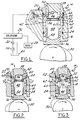
- Figure 1 is a cross-sectional view of the lost motion hydraulic actuator, of the present invention, riding on the base circle of a timing cam;
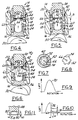
- Figures 2-6 are cross-sectional views of the hydraulic actuator at various times during the rotation of a timing cam;
- Figure 7 is a sectional view taken along line 7-7 of Figure 2 showing thin disc orifice plate;
- Figure 8 is a plan view of the thin disc orifice plate;
- Figure 9 is a timing diagram illustrating the motion of a engine valve, having a fixed timing cycle, according to the timing cam profile; and
- Figure 10 is a timing diagram illustrating the motion of a engine valve in an electronic valve timing system using the lost motion actuator of the present invention under control of an ECU; and
- Figure 11 is another embodiment of the upper or damping piston.
- Referring to the Figures by the characters of reference there is illustrated in Figure 1 in section, the lost motion
hydraulic actuator 14 incorporating the several features of the invention. The fundamental operation of a hydraulic actuator in an internal combustion engine for controlling the opening and closing of the engine valves is well know and will not be detailed here. - The
actuator 14 is mounted in abore 16 in thecylinder head 18 of the engine and is contained there by means of fasteners such as bolts, not shown, passing throughclearance holes 20 in theactuator 14 and being threaded into thecylinder head 18. At least twoseal members actuator 14 to control or prevent leakage of the hydraulic fluid from between theactuator 14 and thebore 16 and into the various volumes in the cylinder head and the engine. The hydraulic fluid in most installations is engine oil. As the temperature of the engine oil changes, from -30°C to +150°, the viscosity of the engine oil varies over a range of three magnitudes (500 Saybolt Universal Seconds, "SUS", to 5 SUS). - The fluid control of the hydraulic fluid is by means of a solenoid actuated
valve 26 controlled by an electronic valve timing control unit orECU 28. The solenoid actuatedvalve 26 is operated to control the flow of the hydraulic fluid to and from theactuator 14 in a manner as described in United States Patent 4,615,306. This is one of several patents describing an electronic valve timing, EVT, system. While an EVT system can not create more valve motion, it can reduce the valve motion created by thetiming cam 30. The EVT system can be programmed to allow standard or full valve lift, as illustrated in Figure 10, down to zero valve lift in any increment. - As illustrated, a one-way valve 32 controls the flow of fluid from a
pump 34 to thecylinder head 18. In its most simplistic operation, when thesolenoid valve 26 is opened, the hydraulic fluid flows into theactuator 14 to maintain the proper amount of fluid therein and to maintain the pressure of the fluid. When thesolenoid valve 26 is closed, the fluid is trapped in theactuator 14 forming a "solid fluid link" that functions to operate theactuator 14 by having thelower piston 36 solidly connected, by the fluid link, to theupper piston 38 so that both reciprocate together. Theupper piston 38 is operatively connected to the engine valve of the engine. Typically the engine valve is biased closed by means of a valve spring which also functions to maintain theupper piston 38 in its normal position as will herein be described. Again, when thesolenoid valve 26 is opened the hydraulic fluid, under the pressure of the valve spring, not shown, flows back to theoil supply 40. TheECU 28 receives various signals from several engine sensors, not shown, and according to predetermined conditions controls the operation of the solenoid actuatedvalve 26. - The
upper piston 38 is slideably located for reciprocal motion in a by-pass sleeve ortubular housing member 42. In its normal position, theupper piston 38 rests on ashoulder 44 as illustrated in Figure 1. The by-pass sleeve 42, in cross-section as indicated in Figure 1, is shaped like an "H" with theupper piston 38 located in anupper chamber 46 above the cross bar of the "H" forming asupport ring 54 and thelower piston 36 located in thelower chamber 48 below the cross bar of the "H". Bothpistons pass sleeve 42. In theupper chamber 46 there is located a second bias orupper spring 50 which biases theupper piston 38 away from the cross bar. Theupper spring 50 is supported at one end by means of anorifice plate 52 resting on asupport ring 54 formed in the cross bar and is located against the bottom of a blind bore in theupper piston 38. - Located axially in the cross bar, is a
chamber passage 56 allowing the flow of fluid between the upper 46 and lower 48 chambers. In thelower chamber 48, is a first bias or lower ortappet spring 58 biasing the lower ortappet piston 36 against thetiming cam 30. Thetiming cam 30 is connected to an engine rotating shaft, typically the engine camshaft, and provides the basic valve opening and closing times for the various engine valves. In a typical engine, there is one cam for each valve and there is at least one intake and one exhaust valve per cylinder. Since this operation is well known, the camshaft and engine are not shown. - Located in and extending through the legs of the "H" shaped by-
pass sleeve 42 are at least one inlet means or spacedports 60 providing passageways for the flow of hydraulic fluid into and out of thelower chamber 48. As illustrated, between theports 60 and along the outside diameter of the by-pass sleeve 42 and formed between the inner diameter of thebore 16 in thecylinder head 18 and the by-pass sleeve, is acircumferential communication passageway 62 functioning to provide a passageway for the flow of hydraulic fluid from the solenoid actuatedvalve 26 to theports 60 and also providing for the flow of fluid between theupper chamber 46 and thelower chamber 48. - Located near the top end of the
communication passageway 60 is acommunication port 64 connecting thecommunication passageway 62 to theupper chamber 46. It is the vertical positioning, "D" as shown in Figures 5 and 10, from the end of thecommunication port 64 to the top of theshoulder 44 in theupper chamber 46 that determines when and where in the valve operation cycle the damping of thelower piston 36 begins. This is further illustrated in Figure 10. - Figures 2-6 show, respectively, the operation of the lost
motion actuator 14. Figure 2 illustrates zero lift when thelower piston 36 is riding on the the base circle of thetiming cam 30. In Figures 3-6, the flow of the hydraulic fluid within theactuator 14 is illustrated by dashed lines when the solenoid actuatedvalve 26 is closed and there is no flow of fluid out of the actuator. Figure 3 illustrates the movement of thepistons lower piston 36 rides on the rising portion of thetiming cam 30 causing the engine valve to begin to open. Figure 4 illustrates the movement of thepistons lower piston 36 approaches the top of thetiming cam 30 and the flow of the hydraulic fluid in the actuator. Figure 5 illustrates the movement of the pistons as the tappet leaves the top of the timing cam as the engine valve is beginning to close. Figure 6 illustrates the movement of thepistons lower piston 36 approaches the base circle of thetiming cam 30. Without the provision of a thinsharp edge orifice 66 in theorifice plate 52 and thecommunication port 64 from theupper chamber 46 to thecommunication way 62, theactuator 14 movement would be very similar to that illustrated by the dashed lines 68 in Figure 10. Figure 9 illustrates the standard lift profile 70 of an engine valve unmodified by EVT. In both Figures 9 and 10, the abscissa is the angle of rotation of the timing camshaft and ordinate is the amount of lift or opening of the engine valve. - Referring to Figure 3, the fluid flows from the
lower chamber 48 through thechamber passage 56 and from there in parallel through theorifice 66 and theflow ring passages 72 between the locating lugs 74 on the orifice plate. Figures 7 and 8 show in greater detail theflow ring passages 72 and locating lugs 74 on theorifice plate 52. The pressure of the fluid being "pumped" by thelower piston 36 causes theorifice plate 52 to lift off of thesupport ring 54 allowing the fluid to flow from thechamber passage 56 through theflow ring passages 72 between the locating lugs 74 of theorifice plate 52. - Referring to Figure 4, the
upper piston 38 has been lifted at least a distance "D" and is clear of the bottom of thecommunication ports 64 in the by-pass sleeve 42. The hydraulic fluid can now flow out of theinlet ports 60, through thecommunication passageway 62 and into theupper chamber 46. This increases the size of the flow routes and therefore increases the amount of fluid flowing from thelower chamber 48 to theupper chamber 46. This is an improvement over previous designs of actuators in that the parasitic losses from the actuator are reduced. The result is a faster rise of theupper piston 38 and the hence the opening of the engine valve. - Figures 5 and 6 illustrate the flow of the hydraulic fluid from the decreasing volume of the
upper chamber 46 to the expanding volume of thelower chamber 48 as the engine valve closes. Until theupper piston 38 slides down to the top of thecommunication ports 64, the fluid flows both through theorifice 66 and through thecommunication ports 64 andcommunication passageway 62. The pressure of the fluid causes theorifice plate 52 to seat on thesupport ring 54 on the cross bar of the by-pass sleeve 42. As theupper piston 38 begins to close off thecommunication ports 64, the flow of the fluid lessens and the damping action of theupper piston 38 begins. This is illustrated in Figure 10, wherein the solenoid actuatedvalve 26 is opened and the fluid can be pushed out of theactuator 14 to allow theupper piston 38 to return to its normal position as illustrated in Figure 1. The effect of this opening is illustrated by the almostvertical descent 76 of the profile curve parallel to the ordinate. Figure 10 illustrates the relationship of the height "D" of thecommunication ports 64 above theshoulder 44 and the beginning of the dampingslope 78 of the closure of the engine valve. - Referring to Figure 11, there is illustrated an alternate embodiment of the
upper piston 38. In high speed operation, camshaft speeds, >3500 RPM, the leadingedge 80 of theupper piston 38 must be relieved by relief means 82 such as a chamfer having an angle "B" and an axial height of "H1". In lieu of a chamfer, the leadingedge 80 may be undercut by means of a stepped surface, not shown. The relationship between the angle "B" and the axial height "H1" is provide a gradual initiation of the damping function as theupper piston 38 covers thecommunication ports 64. The axial height "H1" on the leadingedge 80 of theupper piston 38 is less than the distance "H2", in Figure 1, from the bottom of thecommunication ports 64 above theshoulder 44 in the by-pass sleeve 42. As theupper piston 38 begins to close off thecommunication ports 64, the chamfer 82 allows gradual closing off the fluid flow and hence reduces the pressure pulsations do to abrupt closing thecommunication ports 64. Unwanted pressure pulsations, similar to hydraulic hammer when a flow port is closed very rapidly, operate to provide deviations in valve lift. - The size of the
orifice 66 determines the amount of flow of the fluid from theupper chamber 46 to thelower chamber 48 and hence the total time "T" of damping including controlling theslope 78 of the curve of Figure 10 approaching the base circle. It is well known that as the length of theorifice 66, or the thickness of the orifice plate in the area of the orifice, approaches a thin sharp edge, the viscosity term in the equation for determining the flow of the fluid "falls out" of the equation. It is for this reason that with theorifice plate 52 being of a predetermined thickness to support theupper spring 50 and to move off of thesupport ring 54 during the opening of theactuator 14 as illustrated in Figures 3 and 4, the surface of theorifice plate 52 around theorifice 66 is chamfered to reduce the length of theorifice 66 so as to present a thin sharp edge to the flow of the fluid from theupper chamber 46 to thelower chamber 48. As illustrated the chamfer or bevelled edge is on the surface oforifice disk member 52 facing thelower chamber 48. - It is to be understood, that under the control of the
ECU 28 the slope of the valve operation as illustrated in Figures 9 and 10 may take many different shapes. However, once thesolenoid valve 26 is opened and the fluid flows out of theactuator 14 for a substantial period of time indicating that the valve will be closed, the cooperation between thecommunication ports 64, the bottom or leadingedge 80 of theupper piston 38 and the size of theorifice 66 will control the beginning of the damping slope, "D" in Figure 10 and the decay time or angle "A" as the engine valve approaches and seats in its valve seat.
Claims (6)
- A lost motion hydraulic actuator (14) of an internal combustion engine having a tubular housing member (42) in a bore (16) in the cylinder head (18), a support ring (54) intermediate the ends of the housing dividing the housing into an upper chamber (46) and a lower chamber (48), a lower piston (36) in contact with the timing cam and mounted for reciprocal motion in the lower chamber (48) and biased outward by a first bias spring (58) from the support ring to the lower piston (36), an upper piston (38) mounted for reciprocal motion in the upper chamber (46), at least one inlet (60) through the housing (42) for receiving hydraulic fluid into the lower chamber (48), said actuator (14) characterized in that said upper piston (38) is biased outward by means of a second bias spring (50) and in that said actuator (14) further comprises:a fluid communication passageway (62) intermediate the ends of the housing member (42) between the walls of bore (16) and the outside periphery of the housing member, said communication passageway (62) intersecting the inlet (60) and controlling the flow of hydraulic fluid between the chambers,a communication port (64) connecting said fluid communication passageway (62) with the upper chamber (46), said port (64) being opened and closed by the reciprocal motion of the upper piston (38),an orifice disk plate (52) mounted on the support ring (54) in the upper chamber (46) and biased against the support ring by the second bias spring (50), said disk plate (52) having a plurality of axial flow ring passages (72) around the periphery of said disk plate (52) for allowing flow of hydraulic fluid from the lower chamber (48) to the upper chamber (46) when said disk plate (52) is off of the support ring,a shoulder (44) located in the upper chamber (46) for slideably receiving the upper piston (38) in its normal position when the engine valve is closed and limiting the movement of said disk plate when the fluid flows from the lower chamber to the upper chamber, anda thin orifice (66) centrally located in said orifice disk plate (52) for controlling the flow of hydraulic fluid from the upper chamber (46) to the lower chamber (48) when the upper piston (38) closes said communication port (64) providing damping of the upper piston during the reciprocal movement of the upper piston (38) toward its normal position.
- A lost motion hydraulic actuator (14) of an internal combustion engine according to claim 1 wherein the upper piston (38) has relief means (82) on the leading edge thereof, said relief means for gradually closing said communication port (64) during damping of the upper piston.
- A lost motion hydraulic actuator (14) of an internal combustion engine according to claim 2 wherein said relief means (82) is a chamfer (H1, 80) wherein the axial length (H1) of chamfer determines the beginning of damping relative to the normal position of the upper piston.
- A lost motion hydraulic actuator (14) of an internal combustion engine according to claim 1 wherein the height of the bottom of the communication port (64) above said shoulder (44) determines the beginning of damping and the size of said orifice (66) determines the total time of damping irrespective of the viscosity of the hydraulic fluid during the reciprocal movement of the upper piston (38) toward its normal position.
- A lost motion hydraulic actuator (14) of an internal combustion engine according to claim 1 wherein said orifice disk plate (52) is of a predetermined thickness and the surface around said orifice (66) is chamfered to reduce the length of said orifice to produce a thin sharp edge to said orifice (66).
- A lost motion hydraulic actuator (14) of an internal combustion engine according to claim 5 wherein said chamfer is on the side of said orifice disk member (52) facing the lower chamber (48).
Applications Claiming Priority (3)
| Application Number | Priority Date | Filing Date | Title |
|---|---|---|---|
| US07/862,170 US5158048A (en) | 1992-04-02 | 1992-04-02 | Lost motion actuator |
| US862170 | 1992-04-02 | ||
| PCT/US1993/002406 WO1993020337A1 (en) | 1992-04-02 | 1993-03-17 | Lost motion actuator |
Publications (2)
| Publication Number | Publication Date |
|---|---|
| EP0637358A1 EP0637358A1 (en) | 1995-02-08 |
| EP0637358B1 true EP0637358B1 (en) | 1997-06-11 |
Family
ID=25337848
Family Applications (1)
| Application Number | Title | Priority Date | Filing Date |
|---|---|---|---|
| EP93908362A Expired - Lifetime EP0637358B1 (en) | 1992-04-02 | 1993-03-17 | Lost motion actuator |
Country Status (5)
| Country | Link |
|---|---|
| US (1) | US5158048A (en) |
| EP (1) | EP0637358B1 (en) |
| JP (1) | JPH07505461A (en) |
| DE (1) | DE69311547T2 (en) |
| WO (1) | WO1993020337A1 (en) |
Families Citing this family (29)
| Publication number | Priority date | Publication date | Assignee | Title |
|---|---|---|---|---|
| US5253621A (en) * | 1992-08-14 | 1993-10-19 | Group Lotus Plc | Valve control means |
| US5275136A (en) * | 1991-06-24 | 1994-01-04 | Ford Motor Company | Variable engine valve control system with hydraulic damper |
| EP0614507B1 (en) * | 1991-11-29 | 1996-09-25 | Caterpillar Inc. | Engine valve seating velocity hydraulic snubber |
| US5421359A (en) * | 1992-01-13 | 1995-06-06 | Caterpillar Inc. | Engine valve seating velocity hydraulic snubber |
| US5255639A (en) * | 1992-10-15 | 1993-10-26 | Siemens Automotive L.P. | Integral EVT/cylinder head assembly with self-purging fluid flow |
| US5216988A (en) * | 1992-10-15 | 1993-06-08 | Siemens Automotive L.P. | Dual bucket hydraulic actuator |
| US5241927A (en) * | 1992-10-20 | 1993-09-07 | Rhoads Eugene W | Internal combustion engine with different exhaust and intake valve operating characteristics |
| US5485813A (en) * | 1995-01-11 | 1996-01-23 | Siemens Automotive Corporation | Lost motion actuator with damping transition |
| US5499606A (en) * | 1995-01-11 | 1996-03-19 | Siemens Automotive Corporation | Variable timing of multiple engine cylinder valves |
| US5503120A (en) * | 1995-01-18 | 1996-04-02 | Siemens Automotive Corporation | Engine valve timing control system and method |
| DE19528505A1 (en) * | 1995-08-03 | 1997-02-06 | Schaeffler Waelzlager Kg | Device for selectively actuating at least one gas exchange valve |
| US5996550A (en) * | 1997-07-14 | 1999-12-07 | Diesel Engine Retarders, Inc. | Applied lost motion for optimization of fixed timed engine brake system |
| EP1012446A2 (en) | 1997-08-28 | 2000-06-28 | Diesel Engine Retarders, Inc. | Engine valve actuator with valve seating control |
| KR100565004B1 (en) | 1997-11-04 | 2006-03-30 | 디이젤 엔진 리타더스, 인코포레이티드 | Valve actuation system for cylinders of internal combustion engines |
| KR20010032345A (en) * | 1997-11-21 | 2001-04-16 | 디이젤 엔진 리타더스, 인코포레이티드 | Device to limit valve seating velocities in limited lost motion tappets |
| US8820276B2 (en) * | 1997-12-11 | 2014-09-02 | Jacobs Vehicle Systems, Inc. | Variable lost motion valve actuator and method |
| US6293237B1 (en) * | 1997-12-11 | 2001-09-25 | Diesel Engine Retarders, Inc. | Variable lost motion valve actuator and method |
| US6510824B2 (en) | 1997-12-11 | 2003-01-28 | Diesel Engine Retarders, Inc. | Variable lost motion valve actuator and method |
| IT1302071B1 (en) * | 1998-02-26 | 2000-07-20 | Fiat Ricerche | INTERNAL COMBUSTION ENGINE WITH VARIABLE OPERATION VALVES. |
| US6302370B1 (en) | 1998-08-26 | 2001-10-16 | Diesel Engine Retarders, Inc. | Valve seating control device with variable area orifice |
| EP1212518B1 (en) | 1999-09-16 | 2010-01-06 | Diesel Engine Retarders, Inc. | Method and apparatus for valve seating velocity control |
| US6634862B2 (en) | 2000-09-15 | 2003-10-21 | General Dynamics Advanced Information Systems, Inc. | Hydraulic actuator |
| US20020094274A1 (en) * | 2000-09-15 | 2002-07-18 | Terpay Gregory Weston | Passive device for noise reduction |
| DE10163824A1 (en) * | 2001-12-22 | 2003-07-03 | Ina Schaeffler Kg | Slave unit of a fluid-operated variable valve train of an internal combustion engine |
| US6957634B2 (en) * | 2002-10-04 | 2005-10-25 | Caterpillar Inc. | Engine valve actuator |
| US6883477B2 (en) * | 2002-10-07 | 2005-04-26 | Ricardo, Inc. | Apparatus for deactivating an engine valve |
| FI124120B (en) * | 2008-07-31 | 2014-03-31 | Wärtsilä Finland Oy | Steering arrangement in piston engine |
| US8069828B2 (en) | 2009-08-13 | 2011-12-06 | International Engine Intellectual Property Company, Llc | Intake valve closing hydraulic adjuster |
| KR101371827B1 (en) * | 2012-10-19 | 2014-03-07 | 현대중공업 주식회사 | Variable valve timing apparatus |
Family Cites Families (10)
| Publication number | Priority date | Publication date | Assignee | Title |
|---|---|---|---|---|
| US4223648A (en) * | 1978-12-01 | 1980-09-23 | General Motors Corporation | Hydraulic valve lifter |
| FR2484531A1 (en) * | 1980-06-11 | 1981-12-18 | Renault | IC hydraulic engine valve gear - has two pistons for each valve with control valve operated by seating between them |
| DE3511819A1 (en) * | 1985-03-30 | 1986-10-09 | Robert Bosch Gmbh, 7000 Stuttgart | VALVE CONTROL DEVICE |
| US4796573A (en) * | 1987-10-02 | 1989-01-10 | Allied-Signal Inc. | Hydraulic engine valve lifter assembly |
| JPH01253515A (en) * | 1987-11-19 | 1989-10-09 | Honda Motor Co Ltd | Valve system for internal combustion engine |
| US4892067A (en) * | 1988-07-25 | 1990-01-09 | Paul Marius A | Valve control system for engines |
| US5103779A (en) * | 1989-04-18 | 1992-04-14 | Hare Sr Nicholas S | Electro-rheological valve control mechanism |
| US4977867A (en) * | 1989-08-28 | 1990-12-18 | Rhoads Jack L | Self-adjusting variable duration hydraulic lifter |
| DE3939003A1 (en) * | 1989-11-25 | 1991-05-29 | Bosch Gmbh Robert | HYDRAULIC VALVE CONTROL DEVICE FOR INTERNAL COMBUSTION ENGINES |
| US5088458A (en) * | 1991-02-01 | 1992-02-18 | Siemens Automotive L.P. | Lash adjusted for engine valve actuator assembly |
-
1992
- 1992-04-02 US US07/862,170 patent/US5158048A/en not_active Expired - Fee Related
-
1993
- 1993-03-17 WO PCT/US1993/002406 patent/WO1993020337A1/en not_active Ceased
- 1993-03-17 DE DE69311547T patent/DE69311547T2/en not_active Expired - Fee Related
- 1993-03-17 EP EP93908362A patent/EP0637358B1/en not_active Expired - Lifetime
- 1993-03-17 JP JP5517480A patent/JPH07505461A/en active Pending
Also Published As
| Publication number | Publication date |
|---|---|
| EP0637358A1 (en) | 1995-02-08 |
| DE69311547D1 (en) | 1997-07-17 |
| JPH07505461A (en) | 1995-06-15 |
| WO1993020337A1 (en) | 1993-10-14 |
| DE69311547T2 (en) | 1998-06-04 |
| US5158048A (en) | 1992-10-27 |
Similar Documents
| Publication | Publication Date | Title |
|---|---|---|
| US5158048A (en) | Lost motion actuator | |
| US5216988A (en) | Dual bucket hydraulic actuator | |
| US5127375A (en) | Hydraulic valve control system for internal combustion engines | |
| US5275136A (en) | Variable engine valve control system with hydraulic damper | |
| JP4116385B2 (en) | Multi-cylinder internal combustion engine with variable valve operation and improved valve brake device | |
| JP4637727B2 (en) | Internal combustion engine with variable drive valve driven by a single pumping piston and controlled by a single solenoid valve for each engine cylinder | |
| US5327858A (en) | Flow restriction controlled variable engine valve system | |
| WO1996004469A1 (en) | Hydraulically actuated valve system | |
| US4452186A (en) | Valve control for internal combustion engines | |
| US5485813A (en) | Lost motion actuator with damping transition | |
| US6227154B1 (en) | Valvegear for engines of reciprocating piston type | |
| JPH01253515A (en) | Valve system for internal combustion engine | |
| KR0178534B1 (en) | Valve control arrangement | |
| EP1635045A1 (en) | Internal combustion engine having valves with variable actuation each provided with a hydraulic tappet at the outside of the associated actuating unit | |
| US5233951A (en) | Flow restriction controlled variable engine valve system | |
| US6024296A (en) | Direct control fuel injector with dual flow rate orifice | |
| US4218995A (en) | Hydraulic valve lifter mechanism for internal combustion engine | |
| EP0309468B1 (en) | Variable actuator for a valve | |
| US5413071A (en) | Valve actuating mechanism for an internal combustion engine | |
| JP4639130B2 (en) | INTERNAL COMBUSTION ENGINE HAVING HYDRAULIC OPERATING UNIT FOR CONTROLLING VALVE BY ROCKING OPERATION | |
| EP2832960B1 (en) | Internal combustion engine having a system for variable actuation of the intake valves, provided with an electrically actuated control valve having two ways and three positions | |
| SU1715211A3 (en) | Exhaust valve of internal combustion engine | |
| US20040065285A1 (en) | Variable engine valve actuator | |
| US7237520B2 (en) | Hydraulic valve-lash-adjusting element (HVA) | |
| US5168840A (en) | Temperature compensated damping mechanism for hydraulic engine valve actuator |
Legal Events
| Date | Code | Title | Description |
|---|---|---|---|
| PUAI | Public reference made under article 153(3) epc to a published international application that has entered the european phase |
Free format text: ORIGINAL CODE: 0009012 |
|
| 17P | Request for examination filed |
Effective date: 19940826 |
|
| AK | Designated contracting states |
Kind code of ref document: A1 Designated state(s): DE FR GB IT |
|
| 17Q | First examination report despatched |
Effective date: 19960328 |
|
| GRAG | Despatch of communication of intention to grant |
Free format text: ORIGINAL CODE: EPIDOS AGRA |
|
| GRAH | Despatch of communication of intention to grant a patent |
Free format text: ORIGINAL CODE: EPIDOS IGRA |
|
| GRAH | Despatch of communication of intention to grant a patent |
Free format text: ORIGINAL CODE: EPIDOS IGRA |
|
| GRAA | (expected) grant |
Free format text: ORIGINAL CODE: 0009210 |
|
| AK | Designated contracting states |
Kind code of ref document: B1 Designated state(s): DE FR GB IT |
|
| ET | Fr: translation filed | ||
| REF | Corresponds to: |
Ref document number: 69311547 Country of ref document: DE Date of ref document: 19970717 |
|
| PLBE | No opposition filed within time limit |
Free format text: ORIGINAL CODE: 0009261 |
|
| STAA | Information on the status of an ep patent application or granted ep patent |
Free format text: STATUS: NO OPPOSITION FILED WITHIN TIME LIMIT |
|
| 26N | No opposition filed | ||
| PGFP | Annual fee paid to national office [announced via postgrant information from national office to epo] |
Ref country code: GB Payment date: 20000314 Year of fee payment: 8 |
|
| PGFP | Annual fee paid to national office [announced via postgrant information from national office to epo] |
Ref country code: FR Payment date: 20000328 Year of fee payment: 8 |
|
| PGFP | Annual fee paid to national office [announced via postgrant information from national office to epo] |
Ref country code: DE Payment date: 20000523 Year of fee payment: 8 |
|
| PG25 | Lapsed in a contracting state [announced via postgrant information from national office to epo] |
Ref country code: GB Free format text: LAPSE BECAUSE OF NON-PAYMENT OF DUE FEES Effective date: 20010317 |
|
| GBPC | Gb: european patent ceased through non-payment of renewal fee |
Effective date: 20010317 |
|
| PG25 | Lapsed in a contracting state [announced via postgrant information from national office to epo] |
Ref country code: FR Free format text: LAPSE BECAUSE OF NON-PAYMENT OF DUE FEES Effective date: 20011130 |
|
| REG | Reference to a national code |
Ref country code: FR Ref legal event code: ST |
|
| PG25 | Lapsed in a contracting state [announced via postgrant information from national office to epo] |
Ref country code: DE Free format text: LAPSE BECAUSE OF NON-PAYMENT OF DUE FEES Effective date: 20020101 |
|
| PG25 | Lapsed in a contracting state [announced via postgrant information from national office to epo] |
Ref country code: IT Free format text: LAPSE BECAUSE OF NON-PAYMENT OF DUE FEES;WARNING: LAPSES OF ITALIAN PATENTS WITH EFFECTIVE DATE BEFORE 2007 MAY HAVE OCCURRED AT ANY TIME BEFORE 2007. THE CORRECT EFFECTIVE DATE MAY BE DIFFERENT FROM THE ONE RECORDED. Effective date: 20050317 |