EP0637144B1 - Two-way communication method between portable parts and radio fixed part through a repeater device in a cordless DECT system - Google Patents
Two-way communication method between portable parts and radio fixed part through a repeater device in a cordless DECT system Download PDFInfo
- Publication number
- EP0637144B1 EP0637144B1 EP94200700A EP94200700A EP0637144B1 EP 0637144 B1 EP0637144 B1 EP 0637144B1 EP 94200700 A EP94200700 A EP 94200700A EP 94200700 A EP94200700 A EP 94200700A EP 0637144 B1 EP0637144 B1 EP 0637144B1
- Authority
- EP
- European Patent Office
- Prior art keywords
- rip
- time slot
- rfp
- fixed part
- information packet
- Prior art date
- Legal status (The legal status is an assumption and is not a legal conclusion. Google has not performed a legal analysis and makes no representation as to the accuracy of the status listed.)
- Expired - Lifetime
Links
- 238000000034 method Methods 0.000 title claims description 25
- 238000004891 communication Methods 0.000 title claims description 11
- 230000005540 biological transmission Effects 0.000 claims description 14
- 230000004044 response Effects 0.000 claims description 9
- 238000012546 transfer Methods 0.000 claims description 3
- 108091006146 Channels Proteins 0.000 claims 4
- 230000001755 vocal effect Effects 0.000 description 6
- 230000004048 modification Effects 0.000 description 3
- 238000012986 modification Methods 0.000 description 3
- 230000004913 activation Effects 0.000 description 2
- 230000012447 hatching Effects 0.000 description 2
- 238000009434 installation Methods 0.000 description 2
- 230000009467 reduction Effects 0.000 description 2
- 238000010521 absorption reaction Methods 0.000 description 1
- 230000003044 adaptive effect Effects 0.000 description 1
- 230000008901 benefit Effects 0.000 description 1
- 238000006243 chemical reaction Methods 0.000 description 1
- 230000001934 delay Effects 0.000 description 1
- 238000011161 development Methods 0.000 description 1
- 230000018109 developmental process Effects 0.000 description 1
- 238000010586 diagram Methods 0.000 description 1
- 238000012423 maintenance Methods 0.000 description 1
- 230000008520 organization Effects 0.000 description 1
- 238000000926 separation method Methods 0.000 description 1
- 230000011664 signaling Effects 0.000 description 1
Images

Classifications
-
- H—ELECTRICITY
- H04—ELECTRIC COMMUNICATION TECHNIQUE
- H04B—TRANSMISSION
- H04B7/00—Radio transmission systems, i.e. using radiation field
- H04B7/24—Radio transmission systems, i.e. using radiation field for communication between two or more posts
- H04B7/26—Radio transmission systems, i.e. using radiation field for communication between two or more posts at least one of which is mobile
- H04B7/2603—Arrangements for wireless physical layer control
- H04B7/2606—Arrangements for base station coverage control, e.g. by using relays in tunnels
-
- H—ELECTRICITY
- H04—ELECTRIC COMMUNICATION TECHNIQUE
- H04W—WIRELESS COMMUNICATION NETWORKS
- H04W16/00—Network planning, e.g. coverage or traffic planning tools; Network deployment, e.g. resource partitioning or cells structures
- H04W16/24—Cell structures
- H04W16/26—Cell enhancers or enhancement, e.g. for tunnels, building shadow
Definitions
- the present invention relates to a method for the two-way communication of digital signals among mobile subscriber stations and radio fixed parts by means of repeater devices in a cordless DECT system.
- the systems of private telephony comprise a plurality of radio base transceiver stations distributed in a way to cover the interested area, and linked to a switching network which may be the public one or a switching network of the Private Automatic Branch Exchange (PABX), and private subscriber sets connecting via radio with the radio fixed parts, and they are therefore able to communicate among themselves and other fixed subscribers linked to the public telephone network.
- the links may be of the vocal type or they may allow the exchange of data by occupying the equivalent of one or more vocal "channels".
- the area covered by a radio fixed part or cell is generally quite reduced covering sometimes just a radius of some tens or hundreds of meters.
- Typical applications of the private telephone systems are found in industrial plants where they may replace the installation of a cabled network, and in commercial or urban centers, where they may advantageously replace the public telephone boxes and others.
- the telecommunication network for private telephony is of the digital type.
- the radio access is in particular of the type FDMA -TDMA - TDD.
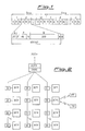
- the system is of the TDD type as transmission and reception do not take place simultaneously. More precisely, as illustrated in figure 1, the base frame of 10 milliseconds is divided in two halves: in the first 5 ms the radio fixed part transmits and the portable sets receive a half frame (the TX DECT half frame for the radio fixed part, and the RX DECT half frame for the portable set), and in the following 5 ms the contrary occurs.
- Each half frame is set up by 12 time slots 1, 2, ..., 12 (from this it results that it is a TDMA system), each one of which is set up by 420 (or according to the some 424) bits.
- the time slots are transmitted or received by using 10 different frequencies (from this it turns out to be an FDMA system) for a total of 120 channels available to the system, which are naturally reassigned to cells sufficiently distant one from the other in order not to create interference problems.
- Each time slot is subdivided in a synchronism field S of 32 bits, in a field A of 8 + 40 bits with relative 16 control bits, and in a field B of 320 bits where bits are allocated which are obtained by coding the vocal samples of a corresponding subscriber.
- Figure 2 shows schematically a typical structure of a DECT network as an example.
- radio fixed parts RFP Radio Fixed Part
- branches in the illustrated example there are 3 branches set up by link lines or dorsals L by means of drop/insert means.
- Each radio fixed part RFPi may handle via radio a certain number of PPs subscribers (Portable Parts) which are generally mobile.
- the branches link up with a battery of transcoders TRAS, and the last one is linked to the Public Switching Telephone Network PSTN through a central control fixed part CCFP.
- the functions carried out by the CCFP may be inserted in a subscriber board of a switching exchange or of a PABX.
- the interface between the CCFP and the DECT network for what regards the vocal signal is typically set up by digital channels of 64 Kbit/s (8000 samples/sec. each one codified by 8 bits).
- a battery of transcoders TRAS is linked providing for the conversion of the PCM transcoding from eight bits used on the PSTN side in an ADPCM coding (Adaptive Differential Pulse Code Modulation) on four bits used on the DECT side.
- the (bi-directional) dorsal at 2.048 Mbit/s connecting the CCFP with the different radio fixed parts RFP supports therefore 48 voice channels plus an undefined number of synchronism and signalling channels.
- the vocal service is supported by the activation of a logical channel called "In minimum delay" on which every 10 msec. in one of the twelve time slots constituting the TDMA DECT frame the bits representing the 80 samples related to one vocal segment of 10 msec are transmitted. These samples together set up a block of 320 bits per frame being transmitted via radio to the portable subscriber part PP in the B field of the DECT slot (see also figure 1).
- the level of the radio signal between the subscriber sets PP and the radio fixed part is not always sufficient to guarantee a good quality link when changing the position of the PPs compared to the RFP.
- a first solution to this problem consists simply in increasing the power of the transceiver unit of the PP sets and of the RFP stations.
- a second solution consists in the installation of repeater devices between the RFP stations and the mobile PP sets.
- Figure 3 shows an operative scenario including a repeater device indicated by RIP, an RFP station and a mobile set PP.
- the signals emitted by the RFP station reach the repeater RIP on a bi-directional radio link indicated by RFP_RIP. These signals are then transmitted by the repeater RIP to the PP set on a bi-directional link RIP_PP.
- the presence of the repeater does not exclude the possibility of a direct bi-directional radio link RFP_PP between the RFP station and the portable part.
- the RIP device should be realized principally in a way maintaining a complete separation and mutual independence between the RFP_RIP and RIP_PP links. This implies a major complexity compared to a normal RFP.
- An object of the present invention is therefore to identify a method making it possible to insert a repeater on the link line between a radio fixed part PPs belonging to a cordless DECT system without the above mentioned drawbacks in terms of introduction of time delays and in terms of reduction of the number of available channels.
- a further object of the present invention is to identify a method allowing the use of PPs which have not to carry out some additional functions compared to the standard ones so to avoid the use of a first typology of handsets when the relay function is applied of the repeater and a second typology of handsets when the relay function is not applied.
- the invention consists more precisely of a method for the two-way communication of digital signals between portable parts and radio fixed part through repeater devices in a cordless DECT system in which the transmission and the reception occur in TDD (Time Division Duplex) modality by the transfer of base frames divided in two half frames, each one being divided in N time slots, during the first of said half frames the portable part being in transmission condition and the radio fixed part being in reception condition, and during the following one of said two half frames the portable part being in reception condition and the radio fixed part being in transmission condition, characterized in that it includes the following steps:
- each one of the equipments RFP, RIP and PP two half frames of 5 ms indicated by SA and SB, respectively.
- Each one of the 12 boxes 1, 2, ..., 12 of the half frame indicates a respective time slot.
- the transmission operations are preceded by the transmission from the RFP unit of a prohibition information for the PP unit to reach a first subgroup of time channels (for example uneven time channels) in order to avoid the attempt by the PP units to get access to channels which are prohibited.
- This prohibition operation is preferably carried out by the PT message (blind slot information).
- the radio fixed part must be adapted in a way to guarantee that the system information turn out to be accessible for all portable parts (for example if the access to the odd time slots has been prohibited the system information have to be transmitted by the RFP at least on one odd time slot).
- the part PP In the half frame SA the part PP is in transmission condition TX while the RFP part is in reception condition RX.
- the portable part PP transmits for example on a time slot 2.
- this time slot 2 is received by the repeater RIP which after having modified some bits of its data field (marking operation) duplicates it in the following time slot, that is in time slot 3, and retransmits it towards the radio fixed part RFP.
- the normal channels are pointed out by a hatching inclined to the left and the duplicated channels by a hatching inclined to the right.
- the repeater RIP passes therefore from phase TX to phase RX not on the basis of half frames but on the basis of a single time slot as also shown in figure 5.
- the dummy is retransmitted changing the identity FMID (Fixed Mac IDentity) of the radio fixed part RFP into the repeater identity RFMID (Repeater Fixed Mac IDentity) and the slot number indication into the chosen slot number when these information are sent.
- identity FMID Fixed Mac IDentity
- RFMID Repeater Fixed Mac IDentity
- the repeater RIP emits the radio signal received in the previous RX slot, if the repeater handles the connection (if not it is always in RX mode).
- the modification (marking operation) the repeater carries out on the data packet received on a time slot consists in setting appropriate bits of A field in a way to mark the TDMA packet as a packet sent by a repeater RIP.
- This type of marking regards obviously only the content of the time slots passing through the repeater RIP and arriving from PP (direction uplink).
- the RFP part Examining the content of the bits of A field of the just received data packet the RFP part is informed about the fact that this packet arrives from the repeater RIP and not directly from the part PP. Then the RFP part sends to the repeater RIP on time slot 1 of the half frame SB a data packet in response to the packet received on time slot 3 in the previous half frame.
- the RFP part is programmed in a way to send a packet to the repeater RIP on the time slot i-2 in response to a packet received from the repeater RIP on time slot i.
- time slot 1 The content of time slot 1 is received by the repeater RIP which duplicates it in the next time slot, that is in time slot 2, and retransmits it to the portable part PP after interference check.
- the unit RIP however provides for the modification of the information related to the slot number allocated in the messages Qt emitted by the RFP unit and changes the FMID into its RFMID when this information appears.
- the unit RIP provides in this way for the incrementation of one unit the current slot number, expressed by means of some bits of A field.
- This incrementation operation allows the part PP to correlate the information Qt with the real position of the time slot.
- the portable part PP having transmitted during the half frame SA on time slot 2 receives in this way a response in the half frame SB on the same time slot 2.
- the RFP receives data packets from PP not marked by a repeater RIP.
- the RFP part simply transmits the response data packet on the time slot corresponding to that on which the data packet has been received in the preceding half frame.
- the unit PP must be adapted to discriminate - in the down-link direction - if it will syntonize on the time slot received from the unit RIP (in the example of figure 4 slot 2) or on the slot received directly from the RFP part (in the example of figure 4 slot 1).
- a possible discriminating criterion for example could be that of syntonizing on the slot most free from troubles or on a predetermined sequence of time slots like for example the odd time slots.
- the capacity of the system RFP-RIP-PP turns out to be reduced in terms of the number of available channels to little less than the half compared to an equivalent system without repeater.
- a further considerable advantage is due to the fact that, at least with reference to the functioning modality countersigned before by the number 2, the mobile part PP has not to carry out any additional function due to the existence of the repeater RIP.
- the portable part PP in fact transmits on one time slot and receives the response on the same time slot in the next half frame without participating at all in the duplication, marking and two-way communication operations of the data packet.
- the invention foresees the realization of the module RIP with a hardware structure similar to that of a radio fixed part RFP or of a device implementing the physical DECT level and the MAC level (Medium Access Control).
- the hardware of a RFP part with space diversity is used (or of a device equipped with two antennas - selectable for example in response to the activation of a switch - which support a unique radio link) it turns out to be convenient, always without departing from the ambit of the invention, always to support a separate radio link by each of the two antennas.
- one of these antennas would support the radio link RIP_PP while the other antenna would support the radio link RIP_RFP.
Landscapes
- Engineering & Computer Science (AREA)
- Computer Networks & Wireless Communication (AREA)
- Signal Processing (AREA)
- Mobile Radio Communication Systems (AREA)
- Time-Division Multiplex Systems (AREA)
Description
- transmitting by means of said portable part a first information packet in a first time slot of the first half frame TX-DECT for the portable part;
- receiving said first information packet through said repeater device connected between said portable part and said radio fixed part;
- storing said first information packet in said repeater device and duplicating it in a second time slot of said first half frame following said first time slot;
- retransmitting in the same half frame to said radio fixed part said first information packet through said repeater device during a second time slot of said first half frame following said first time slot;
- transmitting through said radio fixed part a second information packet in response to said first information packet during a first time slot of said second half frame;
- receiving said second information packet through said repeater device;
- storing said second information packet in said repeater device and duplicating it in a second time slot of said second half frame following said first time slot;
- modifying the information related to the time slot number allocated in the messages emitted by the radio fixed part;
- retransmitting in the same half frame to said portable part said second information packet, through said repeater device, during a second time slot of said second half frame corresponding to the first time slot of said first half frame during which said portable part had previously transmitted said first information packet.
- scans the radio environment looking for a good dummy bearer to lock to, and once lock performed,
- retransmits the detected dummy bearer onto one of the following slots, after interference check, in downlink direction;
- assumes the TX/RX configuration on slot basis and acquires the same radio scanning sequence of the RFP is locked to.
Claims (13)
- Method for the two-way communication of digital signals between portable parts and radio fixed parts through repeater devices (RIP) in a cordless DECT system in which the transmission and the reception occur in TDD that is Time Division Duplex, modality by the transfer of base frames divided in two half frames (SA, SB), each one being divided in N time slots, during the first of said half frames the portable part (PP) being in transmission condition and the radio fixed part (RFP) being in reception condition, and during the following one of said two half frames the portable part (PP) being in reception condition and the radio fixed part (RFP) being in transmission condition, characterized in that it includes the following steps:transmitting by means of said portable part (PP) a first information packet in a first time slot of the first half frame TX-DECT for the portable part (PP);receiving said first information packet through said repeater device (RIP) connected between said portable part (PP) and said radio fixed part (RFP);storing said first information packet in said repeater device (RIP) and duplicating it in second time slot of said first half frame following said first time slot;retransmitting in the same half frame to said radio fixed part (RFP) said first information packet through said repeater device (RIP) during a second time slot of said first half frame (SA) following said first time slot;transmitting through said radio fixed part (RFP) a second information packet in response to said first information packet during a first time slot of said second half frame (SB);receiving said second information packet through said repeater device (RIP);storing said second information packet in said repeater device (RIP) and duplicating it in a second time slot of said second half frame following said first time slot;modifying the information relating to the time slot number allocated in the messages (Qt) emitted by the radio fixed part (RFP);retransmitting in the same half frame to said portable part (PP) said second information packet, through said repeater device (RIP), during a second time slot of said second half frame (SB) corresponding to the first time slot of said first half frame (SA) during which said portable part (PP) had previously transmitted said first information packet.
- Method as claimed in Claim 1, characterized in that it includes the following steps:transmitting from said radio fixed part (RFP) an information addressed to the portable parts (PP) in order to prohibit the access to a predetermined time slots sequence;transmitting through said portable part (PP) said first information packet in a first time slot of the first half frame TX-DECT (SA) for the portable part (PP);receiving said first information packet through said repeater device (RIP);storing said first information packet, after checking the identity (FMID) of the radio fixed part, in said repeater device (RIP) and duplicating it in a second time slot of said first half frame following said first time slot, after interference control;marking said first information packet stored in said repeater device (RIP);retransmitting in the same half frame to said radio fixed part (RFP) said first marked information packet through said repeater device (RIP) during a second time slot of said first half frame (SA) just after said first time slot;transmitting through said radio fixed part (RFP) a second information packet, in response to said first marked information packet, during a first time slot of said second half frame (SB) put ahead by two positions with respect to the first time slot of said first half frame (SA) during which said radio fixed part had received said first information packet;receiving said second information packet through said repeater device (RIP) ;storing said second information packet in said repeater device (RIP) and duplicating it in a second time slot of said second half frame following said first time slot changing the identity (FMID) of the radio fixed part (RFP)into the identity (RFMID) of the repeater (RIP) device;modifying the information relating to the slot number allocated in the messages (Qt) emitted by the radio fixed part (RFP);retransmitting to said portable part (PP) said second information packet through said repeater device (RIP) during a second time slot of said second half frame (SB) immediately after the first time slot of said second half frame (SB) during which said repeater device (RIP) had previously received said second information packet.
- Method as claimed in claim 2, characterized in that said information addressed to the portable parts (PP) prohibits the access to the odd time channels in order not to allow the access to a predetermined channel sequence.
- Method as claimed in claim 2, characterized in that said information addressed to the portable parts (PP) prohibits the access to the even time channels in order not to allow the access to a predetermined sequence of channels.
- Method as claimed in claim 2, characterized in that the transmission by said radio fixed part (RFP) of an information addressed to the portable parts (PP) is carried out by the message PT "blind slot information" in order to prohibit the access to a predetermined time slots sequence.
- Method as claimed in the preceding claims, characterized in that the radio fixed part (RFP) is able to guarantee that the system information turn out to be accessible for all portable parts (PP).
- Method as claimed in claims 1 and 2, characterized in that said modifying operation of the information relating to the slot number emitted by the radio fixed part is carried out by said repeater device (RIP) changing the identity (FMID) of the radio fixed part (RFP) in downlink direction.
- Method according to claim 1 and 2, characterized in that said repeater (RIP) passes from a receiving phase (RX) to a transmitting phase on the base of a single time slot.
- Method as claimed in claim 8, characterized in that said repeater (RIP), just before going in service:scans the radio environment looking for a good dummy bearer to lock to, and once the lock is performed,retransmits the detected dummy bearer onto one of the following slots, after interference check, in downlink direction;assumes the TX/RX configuration on slot basis and acquires the same radio scanning sequence of the RFP is locked to.
- Method as claimed in claim 8, characterized in that said repeater (RIP) during the TX time slot , if handles this connection, emits the radio signal received in the previous RX slots.
- Method as claimed in claim 10, characterized in that said repeater (RIP) during the TX time slot , if does not handle this connection is always in RX mode.
- Method as claimed in claim 9, characterized in that said dummy signal is retransmitted changing the identify FMID, that is Fixed Max IDentity, of the radio fixed part RFP into the repeater identity RFMID, that is Repeater Fixed Mac IDentity, and the slot number indication into the chosen slot number.
- Method as claimed in claim 2 characterized in that said marking operation is an indirect marking.
Applications Claiming Priority (2)
| Application Number | Priority Date | Filing Date | Title |
|---|---|---|---|
| ITMI931716 | 1993-07-30 | ||
| IT93MI001716A IT1266581B1 (en) | 1993-07-30 | 1993-07-30 | METHOD FOR RECEIVING DIGITAL SIGNALS BETWEEN MOBILE EQUIPMENT AND FIXED STATIONS USING REPEATER DEVICES IN A SYSTEM |
Publications (2)
| Publication Number | Publication Date |
|---|---|
| EP0637144A1 EP0637144A1 (en) | 1995-02-01 |
| EP0637144B1 true EP0637144B1 (en) | 2001-09-12 |
Family
ID=11366732
Family Applications (1)
| Application Number | Title | Priority Date | Filing Date |
|---|---|---|---|
| EP94200700A Expired - Lifetime EP0637144B1 (en) | 1993-07-30 | 1994-03-18 | Two-way communication method between portable parts and radio fixed part through a repeater device in a cordless DECT system |
Country Status (4)
| Country | Link |
|---|---|
| EP (1) | EP0637144B1 (en) |
| DE (1) | DE69428241T2 (en) |
| ES (1) | ES2164082T3 (en) |
| IT (1) | IT1266581B1 (en) |
Families Citing this family (13)
| Publication number | Priority date | Publication date | Assignee | Title |
|---|---|---|---|---|
| US5590173A (en) * | 1992-08-05 | 1996-12-31 | Beasley; Andrew S. | Delay insensitive base station-to-handset interface for radio telephone systems |
| SE502074C2 (en) * | 1994-06-10 | 1995-08-07 | Telia Ab | Device for repeaters in radio systems with short range |
| EP0688139A3 (en) * | 1994-06-16 | 1998-12-16 | Ascom Business Systems Ag | Device for extending the operating range of a digital cordless telephone system |
| SE513975C2 (en) * | 1994-08-19 | 2000-12-04 | Telia Ab | Repeater and method for DECT systems |
| GB2299732B (en) * | 1995-04-06 | 1999-08-11 | Nokia Mobile Phones Ltd | A Wireless Base Station |
| IT1273596B (en) * | 1995-04-21 | 1997-07-08 | Italtel Spa | METHOD AND SYSTEM FOR DETERMINING THE PSCN PARAMETER STARTING FROM THE MFN PARAMETER IN A CORDLESS DECT TELEPHONE SYSTEM |
| BR9610080A (en) * | 1995-08-03 | 1999-03-02 | Ericsson Telefon Ab L M | Wireless multi-cellular telecommunication radio system and central control unit |
| WO1997021287A1 (en) * | 1995-12-04 | 1997-06-12 | Advanced Micro Devices, Inc. | System and method for frequency division duplex/time division duplex radio frequency communications |
| WO1997026720A1 (en) * | 1996-01-19 | 1997-07-24 | Pcs Wireless (Ip) Inc. | Delay insensitive basestation-to-handset interface for radio telephone systems |
| WO1997029561A1 (en) * | 1996-02-09 | 1997-08-14 | Siemens Aktiengesellschaft | Radio relay arrangement for extending the range on the radio link of a telecommunication system |
| US6226528B1 (en) | 1996-08-01 | 2001-05-01 | Telefonaktiebolaget Lm Ericsson | Wireless multi-cell radio telecommunication system |
| GB2449230B (en) | 2007-04-24 | 2009-09-02 | Multitone Electronics Plc | Telecommunications system and method |
| JP2020096236A (en) * | 2018-12-10 | 2020-06-18 | パナソニックIpマネジメント株式会社 | Base unit and repeater |
Family Cites Families (5)
| Publication number | Priority date | Publication date | Assignee | Title |
|---|---|---|---|---|
| US2642524A (en) * | 1948-11-04 | 1953-06-16 | Gen Electric Co Ltd | Radio communication system |
| JPS6225523A (en) * | 1985-07-25 | 1987-02-03 | Nec Corp | Radio communication system |
| GB2241851A (en) * | 1990-03-09 | 1991-09-11 | Philips Electronic Associated | Optimising transmitter power in a communications system |
| GB2246490A (en) * | 1990-07-23 | 1992-01-29 | Philips Electronic Associated | Fdm-tdd cordless telephone system measures channel quality for handover |
| US5265150A (en) * | 1991-01-30 | 1993-11-23 | At&T Bell Laboratories | Automatically configuring wireless PBX system |
-
1993
- 1993-07-30 IT IT93MI001716A patent/IT1266581B1/en active IP Right Grant
-
1994
- 1994-03-18 ES ES94200700T patent/ES2164082T3/en not_active Expired - Lifetime
- 1994-03-18 EP EP94200700A patent/EP0637144B1/en not_active Expired - Lifetime
- 1994-03-18 DE DE69428241T patent/DE69428241T2/en not_active Expired - Fee Related
Also Published As
| Publication number | Publication date |
|---|---|
| ITMI931716A1 (en) | 1995-01-30 |
| DE69428241T2 (en) | 2002-06-27 |
| ITMI931716A0 (en) | 1993-07-30 |
| DE69428241D1 (en) | 2001-10-18 |
| IT1266581B1 (en) | 1997-01-09 |
| EP0637144A1 (en) | 1995-02-01 |
| ES2164082T3 (en) | 2002-02-16 |
Similar Documents
| Publication | Publication Date | Title |
|---|---|---|
| US4785450A (en) | Apparatus and method for obtaining frequency agility in digital communication systems | |
| US5506837A (en) | Cellular radio communication system which is selectively convertible into a trunked radio communication system for group calls | |
| AU685643B2 (en) | Tranceiver sharing between acces and backhaul in a wireless digital communication system | |
| EP0226610B1 (en) | Installation with portable, wireless telephone sets | |
| US5745849A (en) | Combination cordless telephone and premise-monitoring alarm system | |
| JP3113671B2 (en) | Communications system | |
| US5127100A (en) | Digital radio communication system and two way radio | |
| US5659879A (en) | Method of covering shadow areas in a cellular mobile radio system and radio booster for implementing this method | |
| EP0637144A1 (en) | Two-way communication method between portable parts and radio fixed part through a repeater device in a cordless DECT system | |
| EP0917773B1 (en) | Communicationsystem for enabling mobile-to-mobile calls and methode for encrypting and authentification | |
| JPH0775151A (en) | Interface device that connects the base station to the private branch exchange | |
| EP0475348A2 (en) | Cordless key telephone system having zone switching function | |
| US5910943A (en) | Method and device in radio based telecommunication system using repeaters | |
| US5570354A (en) | Device for increasing the functional area of a system of digitally operating cordless telephones | |
| HU215310B (en) | Method for operating tdma digital wide area radio system with at least two subsystems | |
| EP0479477B1 (en) | Distributed switching cellular communication system | |
| JP2001519135A (en) | Method and apparatus for efficient wireless transmission of data | |
| US5930240A (en) | Radio frequency communication system with a repeater that operates with a time division multiple access protocol | |
| EP0753220B1 (en) | Arrangement for repeaters in a radio-based communications system | |
| JP2567240B2 (en) | Wireless telephone method and method | |
| US6038221A (en) | Device at telecommunications systems using a pattern of time slots | |
| AU695379B2 (en) | Processing signalling messages in a mobile communication system | |
| EP0722229B1 (en) | Device at telecommunications system | |
| CA1295434C (en) | Apparatus and method for obtaining frequency agility in digital communication systems | |
| JPS61206333A (en) | Mobile communication system |
Legal Events
| Date | Code | Title | Description |
|---|---|---|---|
| PUAI | Public reference made under article 153(3) epc to a published international application that has entered the european phase |
Free format text: ORIGINAL CODE: 0009012 |
|
| AK | Designated contracting states |
Kind code of ref document: A1 Designated state(s): DE ES FR GB IT NL SE |
|
| 17P | Request for examination filed |
Effective date: 19950607 |
|
| 17Q | First examination report despatched |
Effective date: 20000427 |
|
| RAP1 | Party data changed (applicant data changed or rights of an application transferred) |
Owner name: SIEMENS INFORMATION AND COMMUNICATION NETWORKS S.P |
|
| GRAG | Despatch of communication of intention to grant |
Free format text: ORIGINAL CODE: EPIDOS AGRA |
|
| GRAG | Despatch of communication of intention to grant |
Free format text: ORIGINAL CODE: EPIDOS AGRA |
|
| GRAH | Despatch of communication of intention to grant a patent |
Free format text: ORIGINAL CODE: EPIDOS IGRA |
|
| GRAH | Despatch of communication of intention to grant a patent |
Free format text: ORIGINAL CODE: EPIDOS IGRA |
|
| GRAA | (expected) grant |
Free format text: ORIGINAL CODE: 0009210 |
|
| AK | Designated contracting states |
Kind code of ref document: B1 Designated state(s): DE ES FR GB IT NL SE |
|
| REF | Corresponds to: |
Ref document number: 69428241 Country of ref document: DE Date of ref document: 20011018 |
|
| REG | Reference to a national code |
Ref country code: GB Ref legal event code: IF02 |
|
| ET | Fr: translation filed | ||
| REG | Reference to a national code |
Ref country code: ES Ref legal event code: FG2A Ref document number: 2164082 Country of ref document: ES Kind code of ref document: T3 |
|
| PLBE | No opposition filed within time limit |
Free format text: ORIGINAL CODE: 0009261 |
|
| STAA | Information on the status of an ep patent application or granted ep patent |
Free format text: STATUS: NO OPPOSITION FILED WITHIN TIME LIMIT |
|
| 26N | No opposition filed | ||
| PGFP | Annual fee paid to national office [announced via postgrant information from national office to epo] |
Ref country code: SE Payment date: 20040304 Year of fee payment: 11 Ref country code: GB Payment date: 20040304 Year of fee payment: 11 |
|
| PGFP | Annual fee paid to national office [announced via postgrant information from national office to epo] |
Ref country code: NL Payment date: 20040310 Year of fee payment: 11 |
|
| PGFP | Annual fee paid to national office [announced via postgrant information from national office to epo] |
Ref country code: ES Payment date: 20040312 Year of fee payment: 11 |
|
| PGFP | Annual fee paid to national office [announced via postgrant information from national office to epo] |
Ref country code: FR Payment date: 20040323 Year of fee payment: 11 |
|
| PGFP | Annual fee paid to national office [announced via postgrant information from national office to epo] |
Ref country code: DE Payment date: 20040517 Year of fee payment: 11 |
|
| PG25 | Lapsed in a contracting state [announced via postgrant information from national office to epo] |
Ref country code: IT Free format text: LAPSE BECAUSE OF NON-PAYMENT OF DUE FEES Effective date: 20050318 Ref country code: GB Free format text: LAPSE BECAUSE OF NON-PAYMENT OF DUE FEES Effective date: 20050318 |
|
| PG25 | Lapsed in a contracting state [announced via postgrant information from national office to epo] |
Ref country code: SE Free format text: LAPSE BECAUSE OF NON-PAYMENT OF DUE FEES Effective date: 20050319 Ref country code: ES Free format text: LAPSE BECAUSE OF NON-PAYMENT OF DUE FEES Effective date: 20050319 |
|
| PG25 | Lapsed in a contracting state [announced via postgrant information from national office to epo] |
Ref country code: NL Free format text: LAPSE BECAUSE OF NON-PAYMENT OF DUE FEES Effective date: 20051001 Ref country code: DE Free format text: LAPSE BECAUSE OF NON-PAYMENT OF DUE FEES Effective date: 20051001 |
|
| EUG | Se: european patent has lapsed | ||
| GBPC | Gb: european patent ceased through non-payment of renewal fee |
Effective date: 20050318 |
|
| PG25 | Lapsed in a contracting state [announced via postgrant information from national office to epo] |
Ref country code: FR Free format text: LAPSE BECAUSE OF NON-PAYMENT OF DUE FEES Effective date: 20051130 |
|
| NLV4 | Nl: lapsed or anulled due to non-payment of the annual fee |
Effective date: 20051001 |
|
| REG | Reference to a national code |
Ref country code: FR Ref legal event code: ST Effective date: 20051130 |
|
| REG | Reference to a national code |
Ref country code: ES Ref legal event code: FD2A Effective date: 20050319 |