EP0636505B1 - Filler unit for a fuel tank, particularly for a motor-vehicle - Google Patents
Filler unit for a fuel tank, particularly for a motor-vehicle Download PDFInfo
- Publication number
- EP0636505B1 EP0636505B1 EP94111205A EP94111205A EP0636505B1 EP 0636505 B1 EP0636505 B1 EP 0636505B1 EP 94111205 A EP94111205 A EP 94111205A EP 94111205 A EP94111205 A EP 94111205A EP 0636505 B1 EP0636505 B1 EP 0636505B1
- Authority
- EP
- European Patent Office
- Prior art keywords
- unit according
- pipe
- pipes
- tubular
- unit
- Prior art date
- Legal status (The legal status is an assumption and is not a legal conclusion. Google has not performed a legal analysis and makes no representation as to the accuracy of the status listed.)
- Expired - Lifetime
Links
Images

Classifications
-
- B—PERFORMING OPERATIONS; TRANSPORTING
- B60—VEHICLES IN GENERAL
- B60K—ARRANGEMENT OR MOUNTING OF PROPULSION UNITS OR OF TRANSMISSIONS IN VEHICLES; ARRANGEMENT OR MOUNTING OF PLURAL DIVERSE PRIME-MOVERS IN VEHICLES; AUXILIARY DRIVES FOR VEHICLES; INSTRUMENTATION OR DASHBOARDS FOR VEHICLES; ARRANGEMENTS IN CONNECTION WITH COOLING, AIR INTAKE, GAS EXHAUST OR FUEL SUPPLY OF PROPULSION UNITS IN VEHICLES
- B60K15/00—Arrangement in connection with fuel supply of combustion engines or other fuel consuming energy converters, e.g. fuel cells; Mounting or construction of fuel tanks
- B60K15/03—Fuel tanks
- B60K15/04—Tank inlets
-
- B—PERFORMING OPERATIONS; TRANSPORTING
- B29—WORKING OF PLASTICS; WORKING OF SUBSTANCES IN A PLASTIC STATE IN GENERAL
- B29C—SHAPING OR JOINING OF PLASTICS; SHAPING OF MATERIAL IN A PLASTIC STATE, NOT OTHERWISE PROVIDED FOR; AFTER-TREATMENT OF THE SHAPED PRODUCTS, e.g. REPAIRING
- B29C49/00—Blow-moulding, i.e. blowing a preform or parison to a desired shape within a mould; Apparatus therefor
- B29C49/02—Combined blow-moulding and manufacture of the preform or the parison
- B29C49/04—Extrusion blow-moulding
-
- B—PERFORMING OPERATIONS; TRANSPORTING
- B60—VEHICLES IN GENERAL
- B60K—ARRANGEMENT OR MOUNTING OF PROPULSION UNITS OR OF TRANSMISSIONS IN VEHICLES; ARRANGEMENT OR MOUNTING OF PLURAL DIVERSE PRIME-MOVERS IN VEHICLES; AUXILIARY DRIVES FOR VEHICLES; INSTRUMENTATION OR DASHBOARDS FOR VEHICLES; ARRANGEMENTS IN CONNECTION WITH COOLING, AIR INTAKE, GAS EXHAUST OR FUEL SUPPLY OF PROPULSION UNITS IN VEHICLES
- B60K15/00—Arrangement in connection with fuel supply of combustion engines or other fuel consuming energy converters, e.g. fuel cells; Mounting or construction of fuel tanks
- B60K15/03—Fuel tanks
- B60K15/035—Fuel tanks characterised by venting means
-
- F—MECHANICAL ENGINEERING; LIGHTING; HEATING; WEAPONS; BLASTING
- F16—ENGINEERING ELEMENTS AND UNITS; GENERAL MEASURES FOR PRODUCING AND MAINTAINING EFFECTIVE FUNCTIONING OF MACHINES OR INSTALLATIONS; THERMAL INSULATION IN GENERAL
- F16L—PIPES; JOINTS OR FITTINGS FOR PIPES; SUPPORTS FOR PIPES, CABLES OR PROTECTIVE TUBING; MEANS FOR THERMAL INSULATION IN GENERAL
- F16L9/00—Rigid pipes
- F16L9/12—Rigid pipes of plastics with or without reinforcement
- F16L9/127—Rigid pipes of plastics with or without reinforcement the walls consisting of a single layer
Definitions
- the present invention relates to a filler unit for a fuel tank, particularly for a motor-vehicle tank, of the type indicated in the precharacterising part of Claim 1.
- US-A-3187936 discloses such a filler unit.
- Filler units which comprise a fuel inlet pipe and a breather pipe both formed from separate corrugated pipes produced by extrusion of a polyamide-based material, and thus effecting a tight seal with respect to hydrocarbons, but, owing to their high degree of flexibility, these units are awkward to mount and require the use of a plurality of reciprocal connection members and of further elements for fixing to the body disposed along the units in order to enable them to fit along a predetermined path inside the body.
- Filler units are also known in which the fuel inlet pipe and the breather pipe are produced as a single rigid piece of polyethylene by means of a blow-moulding process, the units frequently being subjected to an expensive and harmful fluoridisation process which only improves their sealing partially owing to the poor sealing effect with respect to hydrocarbons which is typical of polyethylene.
- the main object of the present invention is to propose a filler unit of the above-mentioned type provided with an optimal sealing effect with respect to hydrocarbons and which simultaneously permits easy and rapid fitting of the whole unit on the motor-vehicle.
- the filler unit according to the invention is produced with a minimum number of parts, which enables the overall sealing effect of the unit to be optimised, since only a small number of connections is required between the elements of the unit.
- the seal connections which are mainly subject to losses owing to imperfections in the seals which can wear over time, are reduced to the minimum.
- the filler unit to which the present invention relates can be fitted extremely simply and quickly and is notable in that its weight is lower than similar units of known type.
- the filler unit comprises a connection rib which is formed integrally with both pipes and which extends at least over a greater part of their common length.
- the unit is strengthened by the connection rib even though the pipes have thin walls, with all the advantages of the reduction in the overall weight of the unit, and further enabling the pipes to have a large internal section with the same external volume.
- the pipes can have a predetermined degree of flexibility, which is useful, for example, for avoiding pipe fractures in the event of knocks, whilst the whole unit, by virtue of the presence of the rib, is substantially rigid such that its shape is adapted faithfully to a predetermined path relative to the body.
- connection rib lends itself particularly to being used as a support portion for accessory elements of the unit, such as securing brackets or devices for connecting auxiliary pipes to the unit, enabling work on the walls of the pipes of the unit to be avoided, which pipes might not be suitable for these purposes owing to their thinness.
- the subject of the present invention is also a process for producing coupled tubular pipes of plastics material, particularly for a filler unit for a tank of a motor-vehicle, having the features stated in Claim 26.
- US-A-3187936 discloses the features of the precharacterizing part of claim 26.
- a filler unit comprising a tubular fuel inlet pipe 3 and a tubular breather pipe 5 having a smaller cross-section than the pipe 3, disposed adjacent one another, is generally indicated 1.
- a rib 4 principally having the function of strengthening the structure of the unit 1, having a generally flattened shape and extending over at least a greater part of the common length of the pipes 3 and 5, is formed between the pipes 3 and 5.
- the pipes 3 and 5 have respective first ends 3a, 5a which are connectible to a tank (not shown in the drawings).
- the second end 3b of the pipe 3 is associated with connection means 10 enabling the unit 1 to be fixed in correspondence with an opening in the motor-vehicle body (not shown).
- the second end 5b of the pipe 5 is connected to the pipe 3, for example in correspondence with the connection means 10, as will become clear from the following description.
- the pipes 3 and 5 and the rib 4 are produced in a single, substantially rigid piece of polyamide-based plastics material.
- the rib 4 preferably extends along the entire common length of the pipes 3 and 5, with the exclusion of the end zones 3a, 5a and 3b, 5b.
- the fuel inlet pipe 3 preferably has an easily flexible, integral bellows portion 7 disposed in the vicinity of the end 3a in order to assist the tank-connection operation, and the breather pipe 5 is provided with an expansion tank 9 which is disposed adjacent the bellows portion 7 and the function of which is to prevent backflow during the admission of fuel through the pipe 3, and which can advantageously be produced integrally with the pipe 5.
- the bellows portion 7 and/or the expansion tank 9 can be produced separately from the pipes 3, 5 and subsequently be connected to the latter in any known manner.
- a bracket 12 is also provided which is preferably integral or rendered integral with the rib 4, for securing the unit 1 to the motor-vehicle.
- the bracket 12, which may, for example, be provided near to the centre of gravity of the unit 1, enables a greater part of the weight of the unit 1 to be supported, or it may also have the sole function of an intermediate positioning member to the central part of the filler 1.
- the bracket 12 could be supported on a panel disposed so as to surround the intermediate portion of the filler.
- connection means 10 comprise a main tubular body 15 having an end 15a provided with a threaded portion of known type enabling a cap to be screwed on (not shown in the drawings).
- the opposite end 15b of the tubular body 15 is intended to receive externally the second end 3b of the fuel inlet pipe 3 with the interposition of a pair of sealing rings 30.
- An elbowed second tubular body 20, having a smaller cross-section than the tubular member 15, is disposed so as to extend partially parallel to the tubular body 15 and comprises a portion 20b on which the end 5b of the breather pipe 5 is fitted.
- the secondary body 20 further comprises a connection duct 21 between the tubular body 15 and the portion 20b, which opens into a side chamber 21b provided in the substantially central part of the tubular body 15.
- the tubular body 15 further comprises a cup flange 22 or mouthpiece, provided with four holes 23, to be secured by four screws with the interposition of a seal 24, in correspondence with the above aperture provided in the motor-vehicle body.
- the cup element 22 has a hole 29a delimited by a cylindrical wall 29 on which a downflow pipe 28 is fitted with the interposition of a cylindrical connection element 29b.
- the function of the pipe 28 is to collect liquids which can accumulate inside the cup element 2 enabling them to be discharged into a part below the motor-vehicle, thus avoiding overflows from the cup element 22 along the outer surface of the body.
- the downflow pipe 28 is connected to the unit 1 at one or more points by one or more snap-engagement members of known type, preferably provided on the rib 4 and integral therewith, for example on the bracket 12.
- An air passage pipe 25 is connected with one of its ends 25a in correspondence with another hole provided in the wall of the cup element 22 and with the opposite end 25b in correspondence with the side chamber 21b.
- a two-way calibrated safety valve 27 the function of which is to avoid excess pressure building up inside the fuel assembly.
- the valve 27 allows air to pass in both directions until a predetermined pressure threshold is reached, whilst it only allows gas to pass from the exterior to the tank when this threshold is exceeded.
- the second ends 3b, 5b of the pipes 3 and 5 in this case have terminal portions which are substantially coplanar such that, when they are fitted onto the ends 15b and 20b respectively of the tubular members 15 and 20, both can be clamped by a single sealing member 13 the shape of which is substantially a figure-of-eight and which is co-moulded about the ends 3b and 5b of the pipes 3, 5 and the bodies 15 and 20.
- This member 13 enables the pipes 3 and 5 simultaneously to be connected simply and quickly to the connection means 10, so as to ensure an optimal seal of the connection.
- a hollow restrictor element 33 which has a wider inlet section 33a, a substantially conical intermediate portion 33b and a narrow outlet end 33c is inserted inside the tubular body 15.
- the restrictor element is secured internally to the body 15 by snap-engagement means 35 of known type and only shown schematically in Figure 3.
- the narrow outlet end 33c comprises a side aperture 32 through which is disposed a pivoting baffle 37 stressed resiliently by a wire spring 36 towards a transverse position inside the restrictor element 33, so as to close the cavity thereof.
- a corrugated tube 38 is fitted on the restrictor element 33, the function of the tube 38 being to direct the flow of fuel so as to avoid the formation of backflows and counterpressure during the admission of fuel through the pipe 3, and being disposed substantially coaxially inside the pipe 3 and being locked in position by additional snap-engagement means 39 provided on the end 33c.
- the end 5b of the breather pipe 5 opposite the end 5a for connection to the tank is connected directly in correspondence with an intermediate zone of the fuel inlet pipe 3, spaced apart from the end 3b.
- the rib 4 which always extends over a greater part of the common length of the pipes 3 and 5, is formed starting at this connection zone and ending close to the ends 3a and 5b of the two pipes 3, 5.
- the portion 5b connecting the breather pipe 5 to the pipe 3 is shaped such that it prevents or restricts the possibility of fuel being able to pass into the latter during the filling stage, for example this portion 5b can have an elbowed loop with the function of a syphon.
- the corrugated tube 38 can extend beyond the zone connecting the pipe 5 to the pipe 3 in the direction of the end 3a, for the same function.
- the secondary tubular body 20 is not used since the pipes 3 and 5 are already formed in the connected state, and the sealing member 13 is produced, for example, by an annular element co-moulded about the end 3b of the fuel introduction pipe 3 so as to secure it directly to the end 15b of the tubular body 15.
- the assembly of the filler unit 1 inside the motor-vehicle is rendered particularly simple by the fact that it is a single element of substantially rigid plastics material which only requires very few positioning means along its length, since the substantial rigidity of shape is already such that it is maintained along a predetermined path along a portion of the body. Since this unit is substantially rigid, the bellows part 7, which has a high degree of deformability, enables the connection to a tank inlet aperture to be rendered simpler even when the entire unit is already mounted in its definitive position, and also allows dimensional variations and vibrations originating during the operation of the motor-vehicle to be absorbed.
- the process for producing the filler unit according to the invention comprises an initial stage for extruding, in a thermoplastic state, a preliminary tubular body or "parison" of polyamide-based plastics material containing a percentage of an elastomer which is sufficient to enable a blow-moulding process to be performed.
- the length of the parison is substantially equal to the final length of the unit consisting of the pipes 3 and 5.
- the parison is disposed in an open hollow mould shaped so as to define the outer surface of the adjacent pipes 3 and 5 connected to one another by the rib 4.
- the inside of the hollow mould also defines the outer shapes of the expansion tank 9, the bellows portion 7, the connection bracket 12 and the retaining members for the anchorage of the tube 28.
- a pressurised fluid is introduced into the parison according to the technique of blow-moulding, which causes the parison to expand against the walls defined by the mould.
- the unit comprising the pipes 3 and 5 connected by the rib 4 is extracted from the mould and can then undergo manual and/or automatic finishing operations.
- This production process permits the use of a polyamide-based plastics material which has remarkable sealing characteristics with respect to hydrocarbons and which can be processed by blow-moulding by virtue of the fact that it contains at least a percentage of an elastomer.
- the filler unit which is obtained by this process is relatively lightweight owing to the thinness of the walls of the pipes 3, 5 but at the same time it is extremely resistant by virtue of the presence of the rib 4 and, whilst having the same external volume, enables pipes to be obtained which have greater internal cross-sections than those which could be obtained using polyethylene, which requires thick walls, owing to its unsatisfactory degree of sealing with respect to hydrocarbons, and frequently an expensive and harmful final fluoridisation process.
- the parison from which the final filler unit is obtained is produced with integral longitudinal portions of materials having different degrees of rigidity.
- a so-called radial co-extrusion stage is performed which, from a given polyamide base, enables different percentages of an elastomer to be introduced during the extrusion of the parison so as to obtain mechanical characteristics which can vary along the axis of the parison, and in particular different degrees of rigidity in predetermined zones of the parison.
- the pipes 3, 5 are thus, more rigid in correspondence with their substantially central parts and with the second ends 3b, 5b, which are made from a polyamide-based plastics material which is modified by the introduction of a concentration of elastomer which is only sufficient to permit its blow- moulding, whilst, in the vicinity of their first ends 3a, 5a they are produced from a polyamide-based plastics material which is modified by the introduction of a concentration of elastomer which is higher than the remaining part of the pipes, which determines greater flexibility of the bellows portion 7 and of the expansion tank 9.
Landscapes
- Engineering & Computer Science (AREA)
- Mechanical Engineering (AREA)
- Manufacturing & Machinery (AREA)
- Life Sciences & Earth Sciences (AREA)
- Sustainable Development (AREA)
- Sustainable Energy (AREA)
- Chemical & Material Sciences (AREA)
- Combustion & Propulsion (AREA)
- Transportation (AREA)
- General Engineering & Computer Science (AREA)
- Cooling, Air Intake And Gas Exhaust, And Fuel Tank Arrangements In Propulsion Units (AREA)
Description
- The present invention relates to a filler unit for a fuel tank, particularly for a motor-vehicle tank, of the type indicated in the precharacterising part of Claim 1.
- US-A-3187936 discloses such a filler unit.
- Filler units are known which comprise a fuel inlet pipe and a breather pipe both formed from separate corrugated pipes produced by extrusion of a polyamide-based material, and thus effecting a tight seal with respect to hydrocarbons, but, owing to their high degree of flexibility, these units are awkward to mount and require the use of a plurality of reciprocal connection members and of further elements for fixing to the body disposed along the units in order to enable them to fit along a predetermined path inside the body.
- Filler units are also known in which the fuel inlet pipe and the breather pipe are produced as a single rigid piece of polyethylene by means of a blow-moulding process, the units frequently being subjected to an expensive and harmful fluoridisation process which only improves their sealing partially owing to the poor sealing effect with respect to hydrocarbons which is typical of polyethylene.
- The main object of the present invention is to propose a filler unit of the above-mentioned type provided with an optimal sealing effect with respect to hydrocarbons and which simultaneously permits easy and rapid fitting of the whole unit on the motor-vehicle.
- This object is achieved by virtue of the features set forth in Claim 1.
- By virtue of the above characteristics, the filler unit according to the invention is produced with a minimum number of parts, which enables the overall sealing effect of the unit to be optimised, since only a small number of connections is required between the elements of the unit. In particular, the seal connections which are mainly subject to losses owing to imperfections in the seals which can wear over time, are reduced to the minimum.
- Furthermore, the filler unit to which the present invention relates can be fitted extremely simply and quickly and is notable in that its weight is lower than similar units of known type.
- Preferably, the filler unit comprises a connection rib which is formed integrally with both pipes and which extends at least over a greater part of their common length.
- In this way, the unit is strengthened by the connection rib even though the pipes have thin walls, with all the advantages of the reduction in the overall weight of the unit, and further enabling the pipes to have a large internal section with the same external volume. Furthermore, the pipes can have a predetermined degree of flexibility, which is useful, for example, for avoiding pipe fractures in the event of knocks, whilst the whole unit, by virtue of the presence of the rib, is substantially rigid such that its shape is adapted faithfully to a predetermined path relative to the body. The connection rib lends itself particularly to being used as a support portion for accessory elements of the unit, such as securing brackets or devices for connecting auxiliary pipes to the unit, enabling work on the walls of the pipes of the unit to be avoided, which pipes might not be suitable for these purposes owing to their thinness.
- The subject of the present invention is also a process for producing coupled tubular pipes of plastics material, particularly for a filler unit for a tank of a motor-vehicle, having the features stated in Claim 26.
- US-A-3187936 discloses the features of the precharacterizing part of claim 26.
- By virtue of this process it is possible to obtain a filler unit made of polyamide which, unlike polyethylene, enables an optimal seal with respect to hydrocarbons to be obtained for the whole filler unit and moreover enables advantage to be taken of a substantial reduction in the overall production costs, avoiding having to subject the unit to a final fluoridisation process, which involves the use of very harmful substances.
- Further characteristics and advantages of the present invention will become clearer from the following detailed description, given with reference to the appended drawings and for purely non-limiting purposes, in which:
- Figure 1 is a perspective view of the filler unit according to the invention;
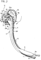
- Figure 2 is a view similar to Figure 1 from a different angle; and
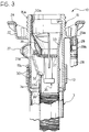
- Figure 3 is an elevation view of a detail of Figure 2 taken along the line III-III.
- With reference to the embodiment shown in the drawings, a filler unit comprising a tubular
fuel inlet pipe 3 and atubular breather pipe 5 having a smaller cross-section than thepipe 3, disposed adjacent one another, is generally indicated 1. Arib 4, principally having the function of strengthening the structure of the unit 1, having a generally flattened shape and extending over at least a greater part of the common length of thepipes pipes - The
pipes first ends second end 3b of thepipe 3 is associated with connection means 10 enabling the unit 1 to be fixed in correspondence with an opening in the motor-vehicle body (not shown). Thesecond end 5b of thepipe 5 is connected to thepipe 3, for example in correspondence with the connection means 10, as will become clear from the following description. - The
pipes rib 4 are produced in a single, substantially rigid piece of polyamide-based plastics material. Therib 4 preferably extends along the entire common length of thepipes end zones - The
fuel inlet pipe 3 preferably has an easily flexible,integral bellows portion 7 disposed in the vicinity of theend 3a in order to assist the tank-connection operation, and thebreather pipe 5 is provided with an expansion tank 9 which is disposed adjacent thebellows portion 7 and the function of which is to prevent backflow during the admission of fuel through thepipe 3, and which can advantageously be produced integrally with thepipe 5. Alternatively, thebellows portion 7 and/or the expansion tank 9 can be produced separately from thepipes - A
bracket 12 is also provided which is preferably integral or rendered integral with therib 4, for securing the unit 1 to the motor-vehicle. Thebracket 12, which may, for example, be provided near to the centre of gravity of the unit 1, enables a greater part of the weight of the unit 1 to be supported, or it may also have the sole function of an intermediate positioning member to the central part of the filler 1. Alternatively, thebracket 12 could be supported on a panel disposed so as to surround the intermediate portion of the filler. - The connection means 10 comprise a main
tubular body 15 having anend 15a provided with a threaded portion of known type enabling a cap to be screwed on (not shown in the drawings). Theopposite end 15b of thetubular body 15 is intended to receive externally thesecond end 3b of thefuel inlet pipe 3 with the interposition of a pair ofsealing rings 30. - An elbowed second
tubular body 20, having a smaller cross-section than thetubular member 15, is disposed so as to extend partially parallel to thetubular body 15 and comprises aportion 20b on which theend 5b of thebreather pipe 5 is fitted. Thesecondary body 20 further comprises aconnection duct 21 between thetubular body 15 and theportion 20b, which opens into aside chamber 21b provided in the substantially central part of thetubular body 15. - The
tubular body 15 further comprises acup flange 22 or mouthpiece, provided with fourholes 23, to be secured by four screws with the interposition of aseal 24, in correspondence with the above aperture provided in the motor-vehicle body. Thecup element 22 has ahole 29a delimited by acylindrical wall 29 on which adownflow pipe 28 is fitted with the interposition of acylindrical connection element 29b. The function of thepipe 28 is to collect liquids which can accumulate inside the cup element 2 enabling them to be discharged into a part below the motor-vehicle, thus avoiding overflows from thecup element 22 along the outer surface of the body. Thedownflow pipe 28 is connected to the unit 1 at one or more points by one or more snap-engagement members of known type, preferably provided on therib 4 and integral therewith, for example on thebracket 12. - An
air passage pipe 25 is connected with one of itsends 25a in correspondence with another hole provided in the wall of thecup element 22 and with theopposite end 25b in correspondence with theside chamber 21b. Along thepipe 25 is interposed a two-way calibratedsafety valve 27 the function of which is to avoid excess pressure building up inside the fuel assembly. In particular, thevalve 27 allows air to pass in both directions until a predetermined pressure threshold is reached, whilst it only allows gas to pass from the exterior to the tank when this threshold is exceeded. - The
second ends pipes ends tubular members single sealing member 13 the shape of which is substantially a figure-of-eight and which is co-moulded about theends pipes bodies member 13 enables thepipes - A
hollow restrictor element 33 which has awider inlet section 33a, a substantially conical intermediate portion 33b and anarrow outlet end 33c is inserted inside thetubular body 15. The restrictor element is secured internally to thebody 15 by snap-engagement means 35 of known type and only shown schematically in Figure 3. - The
narrow outlet end 33c comprises aside aperture 32 through which is disposed apivoting baffle 37 stressed resiliently by awire spring 36 towards a transverse position inside therestrictor element 33, so as to close the cavity thereof. By introducing a fuel delivery nozzle through thebody 15 and thus inside therestrictor element 33, thebaffle 37 moves into a position which is substantially tangential to therestrictor element 33, overcoming the resilient force of thespring 36, so as to open the cavity in theelement 33. - In correspondence with the
end 33c a corrugated tube 38 is fitted on therestrictor element 33, the function of the tube 38 being to direct the flow of fuel so as to avoid the formation of backflows and counterpressure during the admission of fuel through thepipe 3, and being disposed substantially coaxially inside thepipe 3 and being locked in position by additional snap-engagement means 39 provided on theend 33c. - According to a variant of the invention not shown in the drawings, the
end 5b of thebreather pipe 5 opposite theend 5a for connection to the tank is connected directly in correspondence with an intermediate zone of thefuel inlet pipe 3, spaced apart from theend 3b. In this case, therib 4, which always extends over a greater part of the common length of thepipes ends pipes portion 5b connecting thebreather pipe 5 to thepipe 3 is shaped such that it prevents or restricts the possibility of fuel being able to pass into the latter during the filling stage, for example thisportion 5b can have an elbowed loop with the function of a syphon. Moreover, the corrugated tube 38 can extend beyond the zone connecting thepipe 5 to thepipe 3 in the direction of theend 3a, for the same function. - It will be appreciated that, in the event of the
pipe 5 being connected in an intermediate zone of thepipe 3, the secondarytubular body 20 is not used since thepipes sealing member 13 is produced, for example, by an annular element co-moulded about theend 3b of thefuel introduction pipe 3 so as to secure it directly to theend 15b of thetubular body 15. - The assembly of the filler unit 1 inside the motor-vehicle is rendered particularly simple by the fact that it is a single element of substantially rigid plastics material which only requires very few positioning means along its length, since the substantial rigidity of shape is already such that it is maintained along a predetermined path along a portion of the body. Since this unit is substantially rigid, the
bellows part 7, which has a high degree of deformability, enables the connection to a tank inlet aperture to be rendered simpler even when the entire unit is already mounted in its definitive position, and also allows dimensional variations and vibrations originating during the operation of the motor-vehicle to be absorbed. - The process for producing the filler unit according to the invention comprises an initial stage for extruding, in a thermoplastic state, a preliminary tubular body or "parison" of polyamide-based plastics material containing a percentage of an elastomer which is sufficient to enable a blow-moulding process to be performed. The length of the parison is substantially equal to the final length of the unit consisting of the
pipes - Before the unit 1 is shaped, the parison is disposed in an open hollow mould shaped so as to define the outer surface of the
adjacent pipes rib 4. In particular, when these elements are provided integrally with the unit comprising thepipes rib 4, the inside of the hollow mould also defines the outer shapes of the expansion tank 9, thebellows portion 7, theconnection bracket 12 and the retaining members for the anchorage of thetube 28. - Subsequently, with the mould closed, a pressurised fluid is introduced into the parison according to the technique of blow-moulding, which causes the parison to expand against the walls defined by the mould. When the mould has cooled, the unit comprising the
pipes rib 4 is extracted from the mould and can then undergo manual and/or automatic finishing operations. - This production process permits the use of a polyamide-based plastics material which has remarkable sealing characteristics with respect to hydrocarbons and which can be processed by blow-moulding by virtue of the fact that it contains at least a percentage of an elastomer. The filler unit which is obtained by this process is relatively lightweight owing to the thinness of the walls of the
pipes rib 4 and, whilst having the same external volume, enables pipes to be obtained which have greater internal cross-sections than those which could be obtained using polyethylene, which requires thick walls, owing to its unsatisfactory degree of sealing with respect to hydrocarbons, and frequently an expensive and harmful final fluoridisation process. - Preferably, the parison from which the final filler unit is obtained is produced with integral longitudinal portions of materials having different degrees of rigidity.
- In order to attain this characteristic, during the extrusion of the parison, a so-called radial co-extrusion stage is performed which, from a given polyamide base, enables different percentages of an elastomer to be introduced during the extrusion of the parison so as to obtain mechanical characteristics which can vary along the axis of the parison, and in particular different degrees of rigidity in predetermined zones of the parison. The
pipes first ends bellows portion 7 and of the expansion tank 9. - It is thus clear from the above description that, by virtue of the invention, it is possible to obtain a filler unit which has better sealing with respect to hydrocarbons than previously known units without requiring a fluoridisation process, and to enable the
pipes fuel inlet pipe 3 andbreather pipe 5 and with a reduced overall weight of the whole unit.
Claims (30)
- A filler unit for a fuel tank, particularly for a motor-vehicle, comprising:a first tubular pipe (3) for the admission of fuel and a second, tubular breather pipe (5), disposed adjacent one another and having respective first ends (3a, 5a) to be connected to the tank,in which the second end (5b) of the breather pipe (5) is connected to the fuel inlet pipe (3), and connection means (10) are present which are associated with the second end (3b) of the fuel inlet pipe (3) in order to enable it to be anchored in correspondence with an opening provided in the motor-vehicle body, both tubular pipes (3, 5) being formed in a substantially rigid single piece produced from a polyamide-based plastics material,
characterized in that the fuel inlet pipe (3) is provided with a bellows portion (7) in the vicinity of its first end (3a). - A unit according to Claim 1, characterized in that said bellows portion (7) is integral with the fuel inlet pipe (3).
- A unit according to Claim 1 or 2, characterised in that it comprises a connection rib (4) which is formed integrally with both tubular pipes (3, 5) and which extends over at least the majority of their common length.
- A unit according to Claim 2 or 3, characterized in that the breather pipe (5) comprises an integral expansion tank (9) disposed in the vicinity of its first end (5a).
- A unit according to Claim 3 or 4, characterized in that it comprises at least one support bracket (12) integral with the first (3) and second (5) pipes.
- A unit according to Claim 5, characterized in that the support bracket (12) is fixed in correspondence with the connection rib (4).
- A unit according to any one of Claims 1 to 6, characterized in that the breather pipe (5) is connected to the fuel inlet pipe (3) in an intermediate zone thereof and in that the breather pipe (5) has a substantially siphon-like arrangement in correspondence with the connection zone.
- A unit according to any one of Claims 1 to 7, characterized in that both pipes (3, 5) have parts provided with different degrees of rigidity and produced integrally with one another, which can be achieved by a co-extrusion process.
- A unit according to Claim 8, characterized in that the tubular pipes (3, 5) comprise an integral portion produced from a material which is more flexible than the remaining part of the two pipes (3, 5) disposed in the vicinity of the respective first ends (3a, 5a).
- A unit according to Claim 9, characterized in that both tubular pipes (3, 5) are produced from a polyamide-based material comprising a concentration of elastomer which is sufficient to permit blow-moulding of the pipes (3, 5) in correspondence with their second ends (3b, 5b) and of their substantially central parts, and with a polyamide-based material comprising a higher percentage of elastomer relative to the above concentration, in the vicinity of their first ends (3a, 5a) so as to impart greater flexibility to the first ends (3a, 5a) than the remaining parts of the two pipes (3, 5).
- A unit according to any one of Claims 1 to 10, characterized in that the two tubular pipes (3,5) can be shaped by a blow-moulding process.
- A unit according to Claim 1 or 7, characterized in that the connection means (10) comprise a main tubular member (15) provided at one end with a threaded portion (15a) allowing a cap to be screwed on, this main body (15) being able to be connected at the opposite end to the second end (3b) of the fuel inlet pipe (3).
- A unit according to Claim 12, characterized in that the main tubular body (15) is associated with a secondary tubular body (20) having a portion (20b) which is substantially parallel to the main tubular body (15) which is to be connected to the second end (5b) of the breather pipe (5), the main and secondary tubular bodies (15, 20) communicating with one another.
- A unit according to Claim 12 or Claim 13, characterized in that the main tubular body (15) has a cup element (22) which can be secured to the motor-vehicle body.
- A unit according to Claim 14, characterized in that the cup element (22) is provided with a pipe (25) for the passage of gas which is connected to the secondary tubular body (20), a two-way safety valve (27) being interposed in the gas passage pipe (25).
- A unit according to Claim 14 or Claim 15, characterized in that the cup element (22) is provided with a downflow pipe (28) for liquids, connected to the rib (4) by snap-engagement means provided integrally on the rib (4).
- A unit according to any one of Claims 12 to 16, characterized in that the second ends (3b, 5b) of the fuel inlet pipe (3) and breather pipe (5) have substantially co-planar respective terminal portions which are both connected to the connection means (10) by co-moulding in a single sealing part (13) which is substantially in the shape of a figure-of-eight.
- A unit according to Claim 17, characterized in that at least one annular seal (30) is interposed between the fuel inlet pipe (3) and the main tubular body (15).
- A unit according to any one of Claims 12 to 16, characterized in that a hollow restrictor element (33) having an inlet end (33a) facing the threaded portion (15a) and an opposite outlet end (33c) with a narrow section relative to the inlet end (33a) is disposed inside the main tubular body (15).
- A unit according to Claim 19, characterized in that the hollow restrictor element (33) is connected internally to the above main tubular body (15) by snap-engagement means (35).
- A unit according to Claim 19, characterized in that the hollow restrictor element (33) comprises a pivoting baffle (37) which can move normally in a transverse position inside the restrictor element (33) so as to close its cavity and being able to be moved into a position which is substantially tangential to the restrictor element (33), overcoming a resilient return force, following the ingress of a body through the narrow outlet end (33c).
- A unit according to Claim 19, characterized in that a flow directing member (38) is connected to the outlet end (33c) of the restrictor element (33).
- A unit according to Claim 22, characterized in that the flow directing member (38) extends beyond a connection zone of the breather pipe (5) to the fuel inlet pipe (3) in the direction of the first end (3a) of the pipe (3).
- A unit according to Claim 22 or 23, characterised in that the flow directing unit (38) is connected to the restrictor element (33) by snap-engagement means (39).
- A unit according to any one of Claims 22 to 24, characterized in that the flow directing unit comprises a corrugated tube (38) disposed substantially coaxially inside the fuel introduction pipe (3).
- A process for producing coupled tubular pipes (3, 5) of plastics material, particularly for a filler unit (1) for a motor-vehicle tank, the coupled tubular pipes (3, 5) being obtainable by successive operations of extruding and blow-moulding a polyamide-based material, and comprises:the extrusion of a preliminary tubular body or "parison" having a predetermined length, andblow-moulding the "parison" in a hollow mould defining the outer surface of at least a first and a second tubular pipe (3, 5) disposed adjacent one another and jointly having at least one connection portion (4), by supplying a pressurised fluid to the closed mould inside the tubular pipes (3, 5),
characterised in that during the blow-moulding stage of the "parison" a bellows portion (7) in the vicinity of an end (3a) of the first (3) of the tubular pipes (3, 5) is formed. - A process according to Claim 26, characterized in that an integral strengthening rib (4) interposed between the first and the second tubular pipes (3, 5) and extending at least over the greater part of their common length is provide during the blow-moulding stage of the "parison".
- A process according to Claim 27, characterized in that the extrusion operation comprises a co-extrusion stage during which the "parison" is produce with at least two integral portions of polyamide-based materials having respective degrees of rigidity different to one another.
- A process according to any one of Claims 26 to 28, characterized in that the hollow mould is shaped so as to define at least a bracket (12) integral with the strengthening rib (4).
- A process according to any one of Claims 26 to 29, characterized in that the hollow mould is shaped so as to define snap-engagement means integral with the rib (4) for securing a downflow pipe (28) for liquids.
Applications Claiming Priority (2)
| Application Number | Priority Date | Filing Date | Title |
|---|---|---|---|
| ITTO930556 | 1993-07-26 | ||
| ITTO930556A IT1260665B (en) | 1993-07-26 | 1993-07-26 | UNION GROUP FOR A FUEL TANK, PARTICULARLY OF A VEHICLE |
Publications (2)
| Publication Number | Publication Date |
|---|---|
| EP0636505A1 EP0636505A1 (en) | 1995-02-01 |
| EP0636505B1 true EP0636505B1 (en) | 1997-12-29 |
Family
ID=11411645
Family Applications (1)
| Application Number | Title | Priority Date | Filing Date |
|---|---|---|---|
| EP94111205A Expired - Lifetime EP0636505B1 (en) | 1993-07-26 | 1994-07-19 | Filler unit for a fuel tank, particularly for a motor-vehicle |
Country Status (4)
| Country | Link |
|---|---|
| EP (1) | EP0636505B1 (en) |
| DE (1) | DE69407505T2 (en) |
| ES (1) | ES2112450T3 (en) |
| IT (1) | IT1260665B (en) |
Cited By (1)
| Publication number | Priority date | Publication date | Assignee | Title |
|---|---|---|---|---|
| DE102020126002A1 (en) | 2020-10-05 | 2022-04-07 | Röchling Automotive SE & Co. KG | Line system, filling arrangement with line system and method for producing a line system |
Families Citing this family (12)
| Publication number | Priority date | Publication date | Assignee | Title |
|---|---|---|---|---|
| ES2123384B1 (en) * | 1995-06-26 | 1999-08-16 | Walbro Automotive S A | MANUFACTURING PROCEDURE FOR FILLING TUBES FOR FUEL TANKS. |
| FR2746339B1 (en) * | 1996-03-22 | 1998-06-05 | Plastic Omnium Cie | METHOD FOR MANUFACTURING A BEAM OF ATTACHED TUBES, DEVICE FOR CARRYING OUT SUCH A METHOD AND BEAM THUS PRODUCED |
| IT1284714B1 (en) * | 1996-07-30 | 1998-05-21 | Ergom Materie Plastiche Spa | GROUP OF FUEL TANK OF A VEHICLE. |
| DE19716812A1 (en) * | 1997-04-22 | 1998-10-29 | Kautex Textron Gmbh & Co Kg | Motor vehicle tank |
| RU2203190C2 (en) * | 1997-12-19 | 2003-04-27 | Эргом Материе Пластике СПА | Filler pipe unit for fuel tank of motorized vehicle |
| KR100508313B1 (en) * | 1997-12-23 | 2006-05-16 | 에르곰 마테리 플라스티체 에쎄뻬아 | A filler pipe unit for the fuel tank of vehicle |
| FR2774949B1 (en) * | 1998-02-19 | 2000-05-05 | Plastic Omnium Cie | FUEL TANK PROVIDED WITH A DEVICE FOR COMMUNICATING ITS HIGH PARTS |
| DE10227698A1 (en) * | 2002-06-21 | 2004-01-15 | Rasmussen Gmbh | Device for balancing the pressure in a motor vehicle tank |
| DE102006037556B4 (en) * | 2006-08-10 | 2010-04-01 | Thermo-Technik-Systeme Gmbh | Method and blow mold for producing interconnected plastic pipes |
| CN101954858A (en) * | 2010-09-13 | 2011-01-26 | 可附特汽车零部件制造(北京)有限公司 | A kind of oil filling port pipe |
| DE102013100076A1 (en) | 2013-01-07 | 2014-07-10 | Veritas Ag | filling head |
| EP3118041B1 (en) * | 2015-07-16 | 2018-06-27 | Magna Steyr Fuel Systems GesmbH | Improved flow control device for a tank filler neck |
Citations (2)
| Publication number | Priority date | Publication date | Assignee | Title |
|---|---|---|---|---|
| JPH04140587A (en) * | 1990-10-01 | 1992-05-14 | Tokai Rubber Ind Ltd | Resin tube for fuel piping |
| DE4111529A1 (en) * | 1991-03-21 | 1992-09-24 | Inventa Ag | Antistatic polymer pipe esp. for combustible medium e.g. for fuel pipe - has narrow metal tape on inside to earth voltage or charge |
Family Cites Families (12)
| Publication number | Priority date | Publication date | Assignee | Title |
|---|---|---|---|---|
| US3187936A (en) * | 1962-11-01 | 1965-06-08 | Gen Motors Corp | Integral fuel filler pipe and vent tube |
| US3330439A (en) * | 1964-07-17 | 1967-07-11 | Gen Motors Corp | Plastic fuel tank structure |
| US4056344A (en) * | 1970-09-01 | 1977-11-01 | Lemelson Jerome H | Apparatus for producing composite extrusions |
| JPS601025A (en) * | 1983-06-15 | 1985-01-07 | Nissan Motor Co Ltd | Fuel filler tube mounting structure |
| IT206208Z2 (en) * | 1985-11-15 | 1987-07-13 | Italiana Serrature Torino | FUEL SUPPLEMENT BODY FOR VEHICLES |
| DE3540740A1 (en) * | 1985-11-16 | 1987-05-21 | Porsche Ag | FUEL CONNECTOR FOR A FUEL TANK, ESPECIALLY FOR FUEL VEHICLES |
| DE3616291A1 (en) * | 1986-05-14 | 1987-11-19 | Porsche Ag | FUEL CONTAINER FOR FUEL VEHICLES WITH A FUEL FITTING |
| US5186875A (en) * | 1987-04-17 | 1993-02-16 | Mazda Motor Corporation | Method of manufacturing of a novel hollow multi-layer article |
| DE3734782A1 (en) * | 1987-10-14 | 1989-05-03 | Porsche Ag | FUEL CONNECTOR FOR A FUEL TANK OF A MOTOR VEHICLE |
| GB2247880B (en) * | 1990-09-12 | 1994-08-24 | Ford Motor Co | Fuel tank assemblies |
| DE4032869A1 (en) * | 1990-10-17 | 1992-04-23 | Gercke Hans Hermann | Catheter prodn. having flexible gradient - by extrusion of hard and soft plastics in varying proportion |
| DE69110871T2 (en) * | 1991-05-28 | 1995-11-16 | Ford New Holland Ltd | Fuel tank assembly for a vehicle. |
-
1993
- 1993-07-26 IT ITTO930556A patent/IT1260665B/en active IP Right Grant
-
1994
- 1994-07-19 ES ES94111205T patent/ES2112450T3/en not_active Expired - Lifetime
- 1994-07-19 DE DE69407505T patent/DE69407505T2/en not_active Expired - Fee Related
- 1994-07-19 EP EP94111205A patent/EP0636505B1/en not_active Expired - Lifetime
Patent Citations (2)
| Publication number | Priority date | Publication date | Assignee | Title |
|---|---|---|---|---|
| JPH04140587A (en) * | 1990-10-01 | 1992-05-14 | Tokai Rubber Ind Ltd | Resin tube for fuel piping |
| DE4111529A1 (en) * | 1991-03-21 | 1992-09-24 | Inventa Ag | Antistatic polymer pipe esp. for combustible medium e.g. for fuel pipe - has narrow metal tape on inside to earth voltage or charge |
Cited By (1)
| Publication number | Priority date | Publication date | Assignee | Title |
|---|---|---|---|---|
| DE102020126002A1 (en) | 2020-10-05 | 2022-04-07 | Röchling Automotive SE & Co. KG | Line system, filling arrangement with line system and method for producing a line system |
Also Published As
| Publication number | Publication date |
|---|---|
| ITTO930556A0 (en) | 1993-07-26 |
| DE69407505D1 (en) | 1998-02-05 |
| IT1260665B (en) | 1996-04-22 |
| ES2112450T3 (en) | 1998-04-01 |
| DE69407505T2 (en) | 1998-04-16 |
| EP0636505A1 (en) | 1995-02-01 |
| ITTO930556A1 (en) | 1995-01-26 |
Similar Documents
| Publication | Publication Date | Title |
|---|---|---|
| EP0636505A1 (en) | Filler unit for a fuel tank, particularly for a motor-vehicle | |
| US8191568B2 (en) | Fuel tank for motor vehicle | |
| US5305799A (en) | Flexible conduit for vehicle engine coolant circuits | |
| US3187936A (en) | Integral fuel filler pipe and vent tube | |
| US5804268A (en) | Plastic hollow member | |
| US6523576B2 (en) | Fuel hose and method for manufacturing fuel hose | |
| US5723828A (en) | Hollow plastic product having a sound attenuator | |
| CA2228400A1 (en) | Extrusion-blow molded container having cylindrical body and metal mold for producing the same | |
| US7874319B2 (en) | Tube for guiding gas or liquid | |
| US5797373A (en) | Fuel feeding device of motor vehicle | |
| US20020112779A1 (en) | Leak fuel gas discharging structure of automobile | |
| US4431027A (en) | Reservoir for remote fluid system | |
| US6019127A (en) | Structure for connecting filler tube to fuel tank | |
| CA1299523C (en) | Discharge tube | |
| US5829619A (en) | Adapter for motor vehicle fuel filler pipes | |
| US6497335B2 (en) | Filler neck for a fuel tank of a motor vehicle | |
| US4343409A (en) | Large high temperature plastic vacuum reservoir | |
| KR100688042B1 (en) | Tubular carrier | |
| CN102196935A (en) | Fuel tank system and related method of assembly | |
| US5934565A (en) | Washer jet nozzle for a vehicle | |
| US6578537B2 (en) | Welded intake device for an internal combustion engine | |
| US20210341000A1 (en) | Hydro-pneumatic pressure vessel and diaphragm assembly method | |
| CA2158705C (en) | Multi-chamber containers | |
| GB2105666A (en) | Installation for venting a fuel tank | |
| US7090091B2 (en) | Large volume container for holding liquid media |
Legal Events
| Date | Code | Title | Description |
|---|---|---|---|
| PUAI | Public reference made under article 153(3) epc to a published international application that has entered the european phase |
Free format text: ORIGINAL CODE: 0009012 |
|
| AK | Designated contracting states |
Kind code of ref document: A1 Designated state(s): DE ES FR GB IT SE |
|
| 17P | Request for examination filed |
Effective date: 19950712 |
|
| 17Q | First examination report despatched |
Effective date: 19960131 |
|
| GRAG | Despatch of communication of intention to grant |
Free format text: ORIGINAL CODE: EPIDOS AGRA |
|
| GRAH | Despatch of communication of intention to grant a patent |
Free format text: ORIGINAL CODE: EPIDOS IGRA |
|
| RAP1 | Party data changed (applicant data changed or rights of an application transferred) |
Owner name: ERGOM MATERIE PLASTICHE S.P.A |
|
| GRAH | Despatch of communication of intention to grant a patent |
Free format text: ORIGINAL CODE: EPIDOS IGRA |
|
| GRAA | (expected) grant |
Free format text: ORIGINAL CODE: 0009210 |
|
| AK | Designated contracting states |
Kind code of ref document: B1 Designated state(s): DE ES FR GB IT SE |
|
| ITF | It: translation for a ep patent filed | ||
| REF | Corresponds to: |
Ref document number: 69407505 Country of ref document: DE Date of ref document: 19980205 |
|
| PG25 | Lapsed in a contracting state [announced via postgrant information from national office to epo] |
Ref country code: SE Free format text: LAPSE BECAUSE OF FAILURE TO SUBMIT A TRANSLATION OF THE DESCRIPTION OR TO PAY THE FEE WITHIN THE PRESCRIBED TIME-LIMIT Effective date: 19980329 |
|
| REG | Reference to a national code |
Ref country code: ES Ref legal event code: FG2A Ref document number: 2112450 Country of ref document: ES Kind code of ref document: T3 |
|
| ET | Fr: translation filed | ||
| PLBE | No opposition filed within time limit |
Free format text: ORIGINAL CODE: 0009261 |
|
| STAA | Information on the status of an ep patent application or granted ep patent |
Free format text: STATUS: NO OPPOSITION FILED WITHIN TIME LIMIT |
|
| 26N | No opposition filed | ||
| REG | Reference to a national code |
Ref country code: GB Ref legal event code: IF02 |
|
| PGFP | Annual fee paid to national office [announced via postgrant information from national office to epo] |
Ref country code: ES Payment date: 20070615 Year of fee payment: 14 |
|
| PGFP | Annual fee paid to national office [announced via postgrant information from national office to epo] |
Ref country code: DE Payment date: 20070621 Year of fee payment: 14 |
|
| PGFP | Annual fee paid to national office [announced via postgrant information from national office to epo] |
Ref country code: GB Payment date: 20070622 Year of fee payment: 14 |
|
| PGFP | Annual fee paid to national office [announced via postgrant information from national office to epo] |
Ref country code: IT Payment date: 20070725 Year of fee payment: 14 |
|
| PGFP | Annual fee paid to national office [announced via postgrant information from national office to epo] |
Ref country code: FR Payment date: 20070731 Year of fee payment: 14 |
|
| GBPC | Gb: european patent ceased through non-payment of renewal fee |
Effective date: 20080719 |
|
| PG25 | Lapsed in a contracting state [announced via postgrant information from national office to epo] |
Ref country code: DE Free format text: LAPSE BECAUSE OF NON-PAYMENT OF DUE FEES Effective date: 20090203 |
|
| REG | Reference to a national code |
Ref country code: FR Ref legal event code: ST Effective date: 20090331 |
|
| PG25 | Lapsed in a contracting state [announced via postgrant information from national office to epo] |
Ref country code: GB Free format text: LAPSE BECAUSE OF NON-PAYMENT OF DUE FEES Effective date: 20080719 |
|
| PG25 | Lapsed in a contracting state [announced via postgrant information from national office to epo] |
Ref country code: IT Free format text: LAPSE BECAUSE OF NON-PAYMENT OF DUE FEES Effective date: 20080719 Ref country code: FR Free format text: LAPSE BECAUSE OF NON-PAYMENT OF DUE FEES Effective date: 20080731 |
|
| REG | Reference to a national code |
Ref country code: ES Ref legal event code: FD2A Effective date: 20080721 |
|
| PG25 | Lapsed in a contracting state [announced via postgrant information from national office to epo] |
Ref country code: ES Free format text: LAPSE BECAUSE OF NON-PAYMENT OF DUE FEES Effective date: 20080721 |