EP0636422A2 - Improvements in and relating to electrostatic powder coating - Google Patents
Improvements in and relating to electrostatic powder coating Download PDFInfo
- Publication number
- EP0636422A2 EP0636422A2 EP94305476A EP94305476A EP0636422A2 EP 0636422 A2 EP0636422 A2 EP 0636422A2 EP 94305476 A EP94305476 A EP 94305476A EP 94305476 A EP94305476 A EP 94305476A EP 0636422 A2 EP0636422 A2 EP 0636422A2
- Authority
- EP
- European Patent Office
- Prior art keywords
- powder
- particles
- spraying
- finer particles
- classifier
- Prior art date
- Legal status (The legal status is an assumption and is not a legal conclusion. Google has not performed a legal analysis and makes no representation as to the accuracy of the status listed.)
- Granted
Links
Images


Classifications
-
- B—PERFORMING OPERATIONS; TRANSPORTING
- B05—SPRAYING OR ATOMISING IN GENERAL; APPLYING FLUENT MATERIALS TO SURFACES, IN GENERAL
- B05D—PROCESSES FOR APPLYING FLUENT MATERIALS TO SURFACES, IN GENERAL
- B05D1/00—Processes for applying liquids or other fluent materials
- B05D1/02—Processes for applying liquids or other fluent materials performed by spraying
- B05D1/04—Processes for applying liquids or other fluent materials performed by spraying involving the use of an electrostatic field
- B05D1/06—Applying particulate materials
-
- B—PERFORMING OPERATIONS; TRANSPORTING
- B05—SPRAYING OR ATOMISING IN GENERAL; APPLYING FLUENT MATERIALS TO SURFACES, IN GENERAL
- B05B—SPRAYING APPARATUS; ATOMISING APPARATUS; NOZZLES
- B05B14/00—Arrangements for collecting, re-using or eliminating excess spraying material
- B05B14/10—Arrangements for collecting, re-using or eliminating excess spraying material the excess material being particulate
-
- B—PERFORMING OPERATIONS; TRANSPORTING
- B05—SPRAYING OR ATOMISING IN GENERAL; APPLYING FLUENT MATERIALS TO SURFACES, IN GENERAL
- B05B—SPRAYING APPARATUS; ATOMISING APPARATUS; NOZZLES
- B05B7/00—Spraying apparatus for discharge of liquids or other fluent materials from two or more sources, e.g. of liquid and air, of powder and gas
- B05B7/14—Spraying apparatus for discharge of liquids or other fluent materials from two or more sources, e.g. of liquid and air, of powder and gas designed for spraying particulate materials
- B05B7/1404—Arrangements for supplying particulate material
- B05B7/1454—Arrangements for supplying particulate material comprising means for supplying collected oversprayed particulate material
-
- Y—GENERAL TAGGING OF NEW TECHNOLOGICAL DEVELOPMENTS; GENERAL TAGGING OF CROSS-SECTIONAL TECHNOLOGIES SPANNING OVER SEVERAL SECTIONS OF THE IPC; TECHNICAL SUBJECTS COVERED BY FORMER USPC CROSS-REFERENCE ART COLLECTIONS [XRACs] AND DIGESTS
- Y02—TECHNOLOGIES OR APPLICATIONS FOR MITIGATION OR ADAPTATION AGAINST CLIMATE CHANGE
- Y02P—CLIMATE CHANGE MITIGATION TECHNOLOGIES IN THE PRODUCTION OR PROCESSING OF GOODS
- Y02P70/00—Climate change mitigation technologies in the production process for final industrial or consumer products
- Y02P70/10—Greenhouse gas [GHG] capture, material saving, heat recovery or other energy efficient measures, e.g. motor control, characterised by manufacturing processes, e.g. for rolling metal or metal working
Abstract
Description
- This invention relates to powder coating systems for spraying air entrained solid particulate powder material from powder spray guns onto workpieces within a powder spray booth and particularly to a system for controlling and utilizing the finer particulate powder material in any electrostatic powder coating operation.
- Powder spray systems have been used for many years for spraying air entrained solid particulate powder material from electrostatic powder spray guns onto workpieces within a powder coating booth. These systems conventionally collect oversprayed material and re-use it. The recycling system conventionally includes a fan for pulling the oversprayed powder coating material from the powder coating booth into a collector. The collector is comprised of a bank of cartridge filters which separates substantially all of the powder from the air and returns it to the spray guns, or a cyclone recovery system which removes principally only the medium and large powder particles from the air and returns those particles to the spray guns. In a cyclone system, finer particles which are not separated from the air in the cyclone are trapped in a bank of downstream filter cartridges or filter bags. These finer particles, or fines, are normally scrapped.
- A typical powder coating used in these systems has particles that range in size from submicron to 200 microns (µ) Systems for spraying and recycling powder coating materials, particularly those which use cartridge filter collectors as opposed to cyclone recovery systems, often have problems associated with the buildup of excessive amounts of fine particles or "fines." Fines are generally defined as particles with a mean diameter of 10 µ or less. Fines can also be defined in the relative sense as the smaller diameter particles in any given particulate size distribution for a sample of powder coating material.
- There are various theories concerning why fine powder particles tend to build up in these systems. One theory is that, when the particles are sprayed from the gun towards the article to be coated, the heavier particles have greater momentum and, therefore, tend to reach the article or the area around the article more easily. The fine particles, on the other hand, have less momentum, and, therefore, have more difficulty breaking loose from the booth air currents. Another belief is that coarser particles are more easily charged than finer particles due to apparent greater attraction of charging ions to the larger particles. The greater charge on the larger particles causes them to be more strongly attracted to the part being coated. It is also believed that surface repulsion is a factor, that is, that:even if the finer particle with its lower momentum, and lower charge, does reach proximity to the part, it is more likely to be repelled away from the part by the larger particles already on the part due to the fact that both the large and small particles are charged to the same polarity. Therefore, whereas a large charged particle is attracted to the electrical grounding surface presented by the article to be coated, the finer particle is more likely to be repelled by an article surface already covered by larger particles charged to the same polarity as the smaller particles.
- The result of these factors, and possibly others, is that fine particles do not adhere to the part being coated with the same frequency as large particles and instead become entrained in the booth air flow leading into the collection system. In the case of a cyclone collection system many of these fines will not be separated from the air in the cyclone and will arrive at the final filtering system where they will be scrapped (i.e., wasted) and thereby removed from the system. In the case of a cartridge filter collection system the fines will be separated from the air with the other recovered powder. The fines returned from either the cyclone or cartridge recovery system will then be sprayed through the spray gun again where the same factors discussed above again come into play with the result that the fines most likely will again not adhere to the part and will be collected in the recovery system. The result will be, particularly with cartridge filter recovery systems, that the fine particles in the system will build up over time.
- There are many deleterious effects of allowing finer particles to build up in a powder coating system. Too high a concentration of finer particles contributes to low film thickness, poor fluidization in the feed and reclaim hoppers, excessive agglomeration of fine particles (i.e., silting) in pumps, feed lines and guns, reduced efficiency of filters and sieves due to blinding of pores by the finer particles, and increased powder deposition on the guns and booth surfaces. One reason why finer particles are particularly attracted to the booth surfaces is the Van der Waals force which attracts small particles toward larger more massive particles such as the booth walls. Increased powder deposition on the booth walls makes the cleaning of the booth more difficult and time consuming when it is time to change from powder coating with one color of powder to another. Blinding of filters by the finer particles results in the more frequent replacement of filters which is inefficient, time consuming and costly.
- To get the fines out of systems having cartridge filter recovery systems, some powder coating users will simply dump all the powder in the system when the fines concentration becomes excessive. In cyclone recovery systems the fines are more or less being continuously dumped, which reduces the fines concentration in the system. In either type of recovery system, however, the fines are often wasted and not effectively utilized.
- To avoid having to periodically dump all powder from the system, or continually dump fines in cyclone systems, some powder coating users are now sending the fines back to the powder coating material manufacturer for reprocessing or forcing powder coating material manufactures to remove fines before shipping the powder. These methods, however, substantially increase the cost of the powder coating material to the users.
- In a first aspect, powder coating apparatus in accordance with the invention comprises means for spraying solid particulate powder onto workpieces, means for recovering powder oversprayed by the spraying means, a classifier connected to the recovering means for separating finer particles from other particles in the recovered powder, and means for returning the finer particles to the spraying means to be sprayed onto the workpieces.
- Apparatus for powder coating in accordance with a second aspect of the invention comprises means for spraying solid particulate powder onto workpieces, a collector for recovering powder oversprayed by the spraying means, a reclaim hopper connected to the collector for receiving recovered powder therefrom, a classifier to receive recovered powder from the feed hopper and to separate finer particles from other particles in the recovered powder, the recovered powder from which the fines are removed being classified recovered powder, a first feed hopper connected to receive the classified recovered powder from the classifier, means for supplying the spraying means with classified recovered powder, and means for returning the finer particles separated by the classifier to the spraying means to be sprayed onto the workpieces.
- Such arrangements overcome many of the problems of the prior art resulting from wasting finer powder particles and too high a concentration of finer particles by providing an apparatus and method for utilizing and controlling fines and finer particles in a powder spray system. The apparatus separates out finer particles and diverts them to dedicated spraying apparatus from which they can be more effectively applied to parts, so that they are removed from the system. Thus the accumulation of finer particles is prevented by ensuring that they are continuously applied to the parts being coated. By removing finer particles from the system in this way before they build up or before they pass through a cyclone recovery system and are dumped, apparatus in accordance with the present invention improves the overall powder coating system by avoiding the various problems described above.
- One of the factors discussed above affecting the ability of finer particles to adhere to the parts being coated is the relatively poor ability of finer particles to become charged. It is believed that spraying finer particles in the presence of medium size and larger (i.e., coarser) powder coating particles reduces the opportunity for the finer particles to become charged due to the apparently greater attraction of the available charging ions to the coarser powder particles. Therefore, according to the present invention, one or more separate electrostatic spray guns are dedicated to the spraying of finer particles only. The result is that the finer particles do not have to "compete" with coarser particles for the available charging ions, and, therefore, the available charging ions become attracted to the finer particles to charge them and cause them to more readily adhere electrostatically to the part being coated. Using this technique, the finer powder particles will not be wasted by cyclone recovery systems and will not become unduly concentrated in systems employing cartridge recovery systems. Moreover, by dedicating spray guns to spraying finer powder particles, advantages of spraying finer particles alone, such as a finer surface finish on certain parts of the product, can be realized.
- As is suggested above, apparatus in accordance with the invention not only more effectively utilizes fine powder particles as defined above, but also more effectively utilizes "finer" powder particles which can be described in relative terms as the smaller particles of any given particle size distribution present in a powder coating operation. Thus, one teaching of the present invention is that more effective powder charging will occur overall if a narrower particle size distribution is sprayed through a gun than if a broader particle size distribution is sprayed through the gun.
- Another way of saying this is that the buildup of finer particles is related more to the broadening of the particle size distribution curve than it is to the presence of finer particles per se. That is, it is believed that a powder with a small mean particle size can be charged effectively if the distribution is narrow. Therefore, the present invention provides a solution to the build up of finer particles by classifying some or all the powder sprayed into two or more size ranges having narrower distributions than the virgin powder. The finer powder is sprayed through dedicated spray guns, and optimally spray guns which are especially adapted for charging and spraying finer particles. By spraying finer powder through specially adapted spray guns and by utilizing a narrower particle size distribution than virgin powder within these guns, the finer powder can be more effectively coated onto parts.
- It is known that finer powders provide smoother and thinner finishes than coarser particles do. The present invention, therefore, not only provides a solution to the waste or build up of finer particles, but also utilizes the advantages that these finer particles can provide in the coating process. That is, by spraying the finer powder through equipment specially adapted for it onto areas where thinner films and/or better finish are required, a part can be optimally powder coated. According to this novel method, the coarser powder can be used for internal surfaces where surface finish is not as critical, wear areas where thicker coating is desired, or deep recesses where the greater momentum of the heavier powder improves the penetration.
- In accordance with a further aspect of the present invention, apparatus for classifying and collecting powder in a powder spray coating operation comprises a housing forming a collector for receiving oversprayed powder, a classifier located within the housing, the classifier separating finer particles from coarser particles in the recovered powder, means for supplying the coarser particles to a powder spray gun, and means for collecting the finer particles from the classifier and for supplying the finer particles to a dedicated spray gun for spraying fines.
- Such an arrangement provides an integrated separator assembly that combines the elements needed for providing the separation and spraying of finer particles into a single unit that can be easily retrofit on existing systems.
- These and other advantages are provided by the present invention of a powder coating system which comprises means for spraying solid particulate powder on workpieces, means for recovering oversprayed powder, a classifier connected to the recovering means for separating finer particles from other particles, and means for returning the finer particles to the spraying means to be sprayed onto the workpieces.
- In accordance with another aspect of the present invention, a method of powder coating is provided which comprises the steps of spraying solid particulate powder onto workpieces using electrostatic spraying means, recovering oversprayed powder, separating finer particles from other particles and returning the finer particles to the spraying means for spraying onto the workpieces.
- Embodiments of the invention will now be described by way of example and with reference to the accompanying drawings, in which
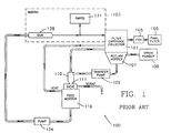
- FIG. 1 is a schematic diagram of a prior art powder recovery and supply system that uses a filter cartridge collector.
- FIG. 2 is a schematic diagram, similar to FIG. 1, showing one embodiment of apparatus in accordance with the present invention in which finer particles are mixed with larger size particles in the feed hopper.
- FIG. 3 is a schematic diagram, similar to FIGS. 1 and 2, showing another embodiment of apparatus in accordance with the present invention in which finer particles are sprayed through a separate spray gun.
- FIG. 4 is a schematic diagram, similar to FIGS. 1-3, showing another embodiment of the present invention in which virgin-powder is also sprayed through a separate gun.
- FIG. 5 is a schematic diagram, similar to FIGS. 1-4, showing another embodiment of the present invention in which virgin powder is preclassified to remove finer particles for separate spraying.
- FIG. 6 is a schematic diagram, similar to FIGS. 1-5, showing another embodiment of the present invention in which virgin powder is classified and the finer particles are mixed with larger size particles in the feed hopper.
- FIG. 7 is a schematic diagram, similar to FIGS. 1-6, showing another embodiment of the present invention in which virgin powder is classified, the finer particles are separately sprayed and the classified virgin powder is separately sprayed.
- FIG. 8 is a perspective schematic view of an integrated classifier which may be used with the apparatus in accordance with the invention.
- FIG. 9 is a schematic diagram, similar to FIG. 1, showing another prior art powder recovery and supply system that employs a cyclone overspray recovery unit.
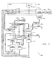
- FIG. 10 is a schematic diagram, similar to FIGS. 1-7, showing another embodiment in which the teachings of the invention are applied to a powder coating system employing a cyclone powder overspray recovery unit.
- FIG. 1 will be described using reference numbers 100-199, the embodiment of FIG. 2 will be described using reference numbers200-299, the embodiment of FIG. 3 will be described using reference numbers 300-399, and so forth. Unless otherwise noted, the elements designated by reference numbers having the same last two digits are similar or identical. For example, element 340 in the embodiment of FIG. 3 would be similar or the same as element 240 in the embodiment of FIG. 2.
- Referring more particularly to the drawings, and initially to FIG. 1, there is shown schematically a
conventional powder system 100 of the prior art. A collector 101 is formed as part of thespray booth 103 and provides means for recovering oversprayed powder oversprayed from thespray booth 103. The oversprayed powder is collected in the collector 101 by means of afan 105 which pulls the over-sprayed powder from thebooth 103 into the collector 101. The collector 101 is a cartridge filter collector such as is shown in U.S. Patent No. 4,590,884 which is incorporated herein by reference in its entirety. The collector 101 houses a bank of cartridge filters which are connected by a clean air plenum to thefan 105. The filtered air drawn by thefan 105 then passes through afinal filter 106 before it is delivered back into the plant. Thefan 105 creates a constant air flow from thebooth 103 into the collector 101.Parts 131 are conveyed through thebooth 103 by an electrically grounded conveyer, and powder sprayed from anelectrostatic spray gun 128 which does not electrostatically adhere to the grounded parts is drawn as oversprayed powder from thebooth 103 into the collector 101. As the air flow passes through the cartridges, the entrained powder accumulates on the exterior of the filter cartridges where it is separated from the air flow. Each of the cartridges is periodically reverse pulse cleaned to knock the accumulated powder off the exterior of the cartridge so that it can fall down into a reclaimhopper 107.Virgin powder 108 is typically introduced into the system by adding it to the reclaimhopper 107 to replace powder used during the coating operation. From the reclaimhopper 107, powder is pumped by atransfer pump 109 to a mini-cyclone 110. The function of the mini-cyclone 110 is to remove the transport air supplied by thepump 109 from the powder flow. The powder flow enters the mini-cyclone 110 tangentially with the heavier powder particles flowing along the interior wall of the cyclone down into the bottom of the mini-cyclone 110. The transport air which carried the powder into the mini-cyclone turns upward at the bottom of the mini-cyclone 110 and flows up along the longitudinal axis of the mini-cyclone 110 and out the top of the mini-cyclone. While the function of the mini-cyclone 110 is solely to remove the transport air and is not to classify the powder by size, unavoidably some of the finer powder particles do not fall out the bottom of the mini-cyclone 110 with the medium size and large particles, but instead remain entrained in the transport air and are exhausted out the top of the mini-cyclone 110 with the transport air. These fine particles are vented into the reclaimhopper 107 with the transport air. The larger particles exit the mini-cyclone 110 and travel through asieve 111. Large conglomerations of powder, oversized powder particles and other impurities are removed from the system at thesieve 111 and are scrapped. The remaining powder particles pass through thesieve 111 and collect in a fluidizedbed feed hopper 116 which is used to supply powder to the spray gun. A representative fluidized feed hopper is shown in U.S. Patent No. 5,018,909 which is hereby incorporated by reference in its entirety. The fluidizing air from thefeed hopper 116 is vented into the collector 101, and this fluidizing air carries with it a quantity of the finer powder particles, since the finer particles naturally tend to concentrate in the upper portion of the hopper. Powder is pumped from thefeed hopper 116 by apump 124 to aspray gun 128 where the powder is sprayed onto theparts 131. The overspray from thegun 128 again returns to the collector 101 as described above. - Using this
prior art system 100, recovered powder and virgin powder are sprayed from thegun 128 onto theparts 131. Recovered powder accumulates in the reclaimhopper 107, andvirgin powder 108 is periodically introduced into the reclaimhopper 107 to replenish the powder supply in the system. - A problem with this
prior art system 100 is that the finer particles tend to accumulate in the system. Finer particles which are separated from the coarser particles in the mini-cyclone 110 are returned to the collector 101 and become trapped in a continuous loop moving from the collector 101 to the reclaimhopper 107 through thetransfer pump 109 to the mini-cyclone 110 and from the mini-cyclone 110 back to the collector 101. Moreover, finer powder particles which do come out the bottom of the mini-cyclone 110 and pass into thefeed hopper 116 are more likely to be vented back to the collector 101 with fluidizing air from thehopper 116. The result is that many of the finer particles never reach the spray gun where they may be sprayed on the parts and removed from the system. Moreover, even if they do reach thespray gun 128, they are not likely to be effectively coated onto theparts 131 for the reasons previously explained, so they tend to flow right past the parts and back into the collector 101. As a result, finer particles tend to accumulate since there is no path out of the system. - Another prior art system employs a cyclone in lieu of the cartridge filter collector 101. This prior art system will be discussed below with reference to FIG. 9. Fines do not become concentrated in a cyclone system because, as discussed above, they are typically continuously dumped to waste.
- FIGS. 2-8 which will next be described show the use of the invention with a cartridge filter type overspray recovery collector, and the invention is described principally with respect to this type of collector for convenience. The invention is, however, also suitable and provides advantages with a cyclone type overspray recovery system, and one way in which this would be accomplished will be discussed below with reference to FIG. 10.
- The
system 200 of FIG. 2 is somewhat similar to the prior art system of FIG. 1 in that it has acartridge filter collector 201 formed as part of spray booth 203 and providing means for recovering oversprayed powder, thecollector 201 having afan 205 connected to afinal filter 206 and having a bank of filter cartridges positioned over a reclaimhopper 207, with atransfer pump 209 on thehopper 207.Virgin powder 208 is introduced into the system by adding it to the reclaimhopper 207 to replace powder used in the powder coating operation. In this system, however, the recovered and virgin powder transported from thehopper 207 by thepump 209 is delivered through asieve 211 to aclassifier 214. Thesieve 211 removes large agglomerations of powder, oversized powder particles and other impurities which are scrapped and allows the remaining particles to go to theclassifier 214. Theclassifier 214 divides the incoming powder into relatively fine particles which are diverted out the top of the classifier and relatively coarse particles which are diverted out the bottom of theclassifier 214. An example of a particle size classifier which could be used for this purpose is an Alpine Multiplex® MZF Flybed Zig-Zag Classifier manufactured by Micron Powder Systems Company of Summit, New Jersey. The coarse particles are deposited from the bottom of theclassifier 214 by gravity, and the finer particles flow out the top of theclassifier 214 with the transport air. This is the general principle of many particles classifiers, to cause the heavier particles to fall out of the transport air flow by gravity, and thereby separate the finer particles from the coarser (i.e., heavier) particles, in that the finer particles tend to remain with the transport air. In thesystem 200, the coarser particles are deposited from the bottom of theclassifier 214 into afeed hopper 216, and the finer particles which exit the top of theclassifier 214 are not returned to thecollector 201, but instead are sent to amixer 223 in thefeed hopper 216. Themixer 216 mixes the finer particles in with the coarser particles before pumping them to aspray gun 228. In this way, some of the finer particles will become attached to the coarser particles due to the Van der Waals force and will be applied with the coarser particles toparts 231. Note, however, that since thehopper 216 is vented to allow the fluidizing air to escape, some of the finer particles will end up returning to thecollector 201 from thehopper 216 with the fluidizing air. However, more of the finer particles will be pumped from thepump 224 to thegun 228 than is the case with theprior art system 100 of FIG. 1. Therefore, the finer particles have a better chance of either adhering to larger powder particles and adhering to one of theparts 231, or becoming sufficiently charged themselves to adhere to one of theparts 231 so that they can be removed from the system. - One problem with the
system 200 of FIG. 2, however, is that the finer particles which do not attach to larger particles for the most part will still not adhere to thepart 231 being coated for the reasons previously explained and will, therefore, end up in thecollector 201. - A system 300 which will utilize the finer particles in the system to a greater degree is shown in FIG. 3 in which the finer particles are fed to a special fines gun and sprayed onto the parts. The system 300 of FIG. 3 is somewhat similar to the
prior system 200 already discussed in that it includes a filter cartridge collector 301 formed as part of spray booth 303, a fan 305, a final filter 306, a reclaim hopper 307, a transfer pump 309, a sieve 311, and a classifier 314. Virgin powder 308 is introduced into the system by adding it to the reclaim hopper 307 to replace powder used in the coating process. The larger particles from the classifier 314 drop into a feed hopper 316. The feed hopper 316 is used to supply powder to a spray gun 328 by means of a pump 324. The finer particles from the classifier 314 are fed to a special fines collector 319 which can be a cartridge filter collector like the collector 301. A fan 320 draws the finer particles delivered from the classifier 314 with the transport air onto filter cartridges and then passes the filtered air through a final filter 321 for delivering it back into the plant. The filter cartridges in the fines collector 319 are periodically pulsed to knock powder down into a fines hopper 322. A transfer pump 327 transfers the relatively fine powder from the hopper 322 to a spray gun 330, which in the preferred embodiment, is especially adapted for charging finer powder particles and spraying them onto the parts 331. One example of a preferred gun is disclosed in copending U.S. Patent Application Serial No. 07/956,615, assigned to the owner of the present invention, the disclosure of this patent application being hereby incorporated by reference in its entirety. The excess powder or overspray from the fines gun 330 which does not electrostatically adhere to the parts 331 is drawn into the collector 301 along with the overspray from the gun 328. However, once these finer particles are pumped from the reclaim hopper 307 by the pump 309 into the classifier 314, they are returned to the fines collector 319 and sent through the fines gun 330 again so that they have another opportunity to be charged and applied to the parts 331. By processing the finer particles in this way, the finer particles will not continually build up in the system as they do in systems of the type shown in FIG. 1. - In addition, since it is known that finer powders provide smoother and thinner finishes than coarser ones do, the system 300 provides a solution to the build up of finer particles by using the advantages of the finer particles to spray them by means of a specially adapted fines gun 330. Thus the process not only solves the problem of build up of finer particles, it also provides a better finish on the parts being sprayed.
- The concept of FIG. 3 of using separate spray guns for the finer particles may be taken one step further by providing a dedicated gun for spraying only the virgin powder. This is shown in the
system 400 of FIG. 4. Thesystem 400 of FIG. 4 is generally similar to the system 300 just described with reference to FIG. 3 with a collector 401 formed as part ofspray booth 403, afan 405, afinal filter 406, a reclaimhopper 407, atransfer pump 409, asieve 411, afilter cartridge classifier 414, and afeed hopper 416. Powder from thefeed hopper 416 is fed using apump 424 to aspray gun 428. Finer particles from theclassifier 414 are sent to afines collector 419 from where they are deposited into afines hopper 422 and pumped using apump 427 to afines gun 430. Instead of introducing virgin powder into the reclaimhopper 407, however, thevirgin powder 408 is introduced into the system through aspecial feed hopper 418 which is used to hold only virgin material. The virgin material enters thefeed hopper 418 through asieve 413 which is used to separate out large clumps or accumulations of powder that may be present in the virgin supply. The fluidizing air for the virginpowder feed hopper 418 is vented into thefines collector 419 so that any finer particles which are fluidized out of thehopper 418 end up in thefines collector 419. The virgin powder from thefeed hopper 418 is then fed using apump 425 to aseparate spray gun 429 for the virgin powder. The oversprayed virgin powder which does not adhere to the parts 431 is drawn into the collector 401 by thefan 405 along with the overspray from theguns - Using the
system 400, virgin powder is separately applied through thegun 429 onto the parts 431. Separating the virgin powder from the reclaimed powder is advantageous because the virgin powder will have a higher concentration of larger size particles than the reclaimed powder since the larger sized powder is most easily charged and applied to the parts 431. The reclaimed powder is likely to have a higher concentration of medium to smaller sized particles. Thus, each of theguns - It is noted that the virgin powder sprayed from the
virgin powder gun 429 in FIG. 4 is actually a mixture of finer and coarser powder particles, and that the finer powder in the virgin powder could be sprayed from the fines gun instead of spraying it from a separate virgin powder gun. The remainder of the virgin powder could then be mixed with the recovered powder. This concept is shown thesystem 500 of FIG. 5. Thesystem 500 of FIG. 5 is generally similar to thesystem 400 just described with a collector 501 formed as part ofspray booth 503, afan 505, afinal filter 506, a reclaimhopper 507, atransfer pump 509, asieve 511, aclassifier 514, and afeed hopper 516. Thesystem 500 uses two guns, aprimary gun 528 and afines gun 530, similar to the guns 328 and 330 of FIG. 3.Virgin powder 508 is loaded into abulk container 518, such as the Nordson® Bulk Unloader shown in U.S. Reissue Patent No. 32,841, the disclosure of which is hereby incorporated by reference in its entirety. Apump 526 pumps the virgin powder from thecontainer 518 through asieve 512 to theclassifier 514. Theclassifier 514 also receives reclaimed powder from the reclaimhopper 507 by means of atransfer pump 509. Theclassifier 514 diverts the finer particles to afines collector 519 and the coarser particles to thefeed hopper 516. The finer particles from the virgin powder along with the finer particles from the recovered material pass from thefines collector 519 into afines hopper 522 from which they are sent to afines gun 530 using apump 527 for spraying onto parts 531. The larger sized particles from the virgin material, along with the larger sized particles from the recovered material, are deposited by theclassifier 514 into thefeed hopper 516 from which they are fed to the reclaimgun 528 using thepump 524. - The concepts of the
systems system 600 of FIG. 6. Thesystem 600 of FIG. 6 is generally similar to thesystem 500 just described with a filter cartridge collector 601 formed as part ofspray booth 603, afan 605, afinal filter 606, a reclaimhopper 607, atransfer pump 609, and asieve 611. Thesystem 600 of FIG. 6 includes aclassifier 614, but the finer particles diverted up and out of theclassifier 614 are not pumped to a separate fines gun. Instead, the finer particles are fed to amixer 623 associated with afeed hopper 616, where the finer particles are mixed with the larger sized particles fed to thefeed hopper 616 from theclassifier 614. Themixer 623 could be an impingement type mixer which would spray the finer powder into the fluidized bed of larger sized particles in thehopper 616. During the mixing process at least some of the finer particles will become agglomerated with some of the larger particles and will be applied as agglomerated particles to the parts 631. - Another alternative to the
system 500 of FIG. 5 is shown in thesystem 700 of FIG. 7. As with thesystem 500, the finer particles contained in the virgin powder can be better used in the fines gun rather than spraying these particles along with the rest of the virgin powder in the conventional gun. However, thesystem 500 uses the remainder of the virgin powder in the same spray gun with the recovered powder. The virgin powder with the finer particles removed may be better used in a separate virgin gun as in thesystem 400. This is accomplished in thesystem 700 of FIG. 7 in which the virgin powder is classified by immediately separating the finer particles from the coarser ones before the virgin powder is delivered to the spray gun. Thesystem 700 of FIG. 7 is similar to thesystem 500 of FIG. 5 with a collector 701 formed as part ofspray booth 703, afan 705, afinal filter 706, a reclaimhopper 707, atransfer pump 709, asieve 711, aclassifier 714, and afeed hopper 716. Finer particles from theclassifier 714 are diverted to afines hopper 722. Virgin powder is supplied to abulk container 718 where it is fed using apump 726 through asieve 712 into asecond classifier 715. The finer particles from theclassifier 714 are sent along with the finer particles from theclassifier 715 to thefines collector 719 where they are sent to afines gun 730 by means of apump 727. The larger sized particles from the 715 are sent to afeed hopper 717. The classified powder from thefeed hopper 717 is sent by means of apump 725 to adedicated gun 729. Thegun 729, therefore, sprays only virgin powder which has been classified to remove the finer powder particles. Thus thegun 729 only charges a relatively narrow particle size distribution of powder which means that a greater portion of the powder sprayed is effectively charged and adheres to theparts 731. Thisgun 729 can, therefore, operate in a very efficient manner and will produce less overspray than other spray guns. - A variation on the "remote classifier" approach shown in FIGS. 2-7 is the embodiment of FIG. 8 which shows a classifier integrated into the collection hopper. According to this approach, an
integrated classifier 70 comprises ahousing 71 which supports both a bank offilter cartridges 72 and a classifier/fines hopper assembly 73. The cartridge filters 72 collect oversprayed powder from the powder coating booth in the normal manner. Afan 74 acting through aclean air plenum 75 and thecartridges 72 draw oversprayed powder from the powder coating booth onto thecartridges 72. Thecartridges 72 are periodically pulse cleaned by reverse-pulse valves 76 to knock the powder off the exterior of thecartridges 72 and down intocollection hoppers hoppers cyclone 81. The powder enters thecyclone 81 tangentially and swirls around the inside of the cyclone with the heavier particles hitting the interior wall and falling towards the bottom of thecyclone 81 and the lighter particles being exhausted out the top of the cyclone with the transport air through anoutlet 82 and into afines collection chamber 83. The heavier (i.e., coarser) particles which are deposited out the bottom of thecyclone 81 pass through aduct 84 into a sieve 85, which removes clumps and impurities, before passing the coarser powder into afeed hopper 86. The powder is pumped from thehopper 86 to a spray gun dedicated to spraying coarser powder by apump 87. - The finer powder particles which enter the
fines collection chamber 83 are drawn onto afilter cartridge 88 by thefan 74 acting through theclean air plenum 75. Thecartridge 88 is periodically reverse-pulsed by apulse valve 89 to knock the finer particles off thecartridge 88 into afines collection hopper 90. A fluidizingair plenum 91 is located under thehopper 90 to fluidize the powder in thehopper 90 so that it can be pumped by the apump 92 to a sieve and feed hopper (not shown) for delivery to a spray gun dedicated to spraying finer particles. - An alternative embodiment of the
integrated classifier 70 would be to geometrically configure thehopper 77 so that it is large enough to completely underlie the sixfilter cartridges 72 and thehopper 78 so that it is small enough to just underlie the lower end of the classifyingcyclone 81. With this alternative embodiment, only thepump 79 would be connected to the classifyingcyclone 81, and thepump 80 would pump the coarser particles discharged from thecyclone 81 to the sieve 85. - In either embodiment, the
integrated classifier 70 provides a single unit that may be retrofit on existing systems to provide the necessary apparatus to classify finer powder particles so that they may be supplied to a fines gun for spraying on parts. - While FIGS. 1-8 show the application of the invention to powder coating systems having cartridge filter overspray collectors, the invention is also applicable to cyclone type recovery systems. FIG. 9 shows a conventional prior
art powder system 900 that employs a cyclone overspray recovery unit. An inertial separator orcyclone 902 is connected to aspray booth 903. Oversprayed powder conveyed by containment air from thespray booth 903 enters thecyclone 902 tangentially, and the heavier and larger particles flow along the interior wall of the cyclone down into the bottom of thecyclone 902. The finer particles and the transport air which carried the powder into thecyclone 902 turn upward at the bottom of the cyclone and flow up along the longitudinal axis of the cyclone and out the top of the cyclone. The finer particles along with the transport air enter acartridge filter collector 904 where the air is exhausted from the collector by afan 905 through afinal filter 906. The finer particles are reverse pulsed off the cartridges in thecollector 904 and fall from the collector into ascrap hopper 922. - The larger particles exit the bottom of the
cyclone 902 and travel through asieve 911. Large agglomerations of powder, oversized power particles and other impurities are removed from the system at thesieve 911 and are scrapped. The remaining powder particles pass through thesieve 911 and collect in a fluidized reclaimhopper 907.Virgin powder 908 is typically introduced into the system by adding it to the reclaimhopper 907 to replace powder used during the coating operation. Powder is pumped from the reclaimhopper 907 to aspray gun 928 where the powder is sprayed onto theparts 931. The overspray from thegun 928 again returns to thecyclone 902 as described above. It can be seen that most of the finer particles are separated from the system by thecyclone 902 where they are collected in thehopper 922 and are scrapped or returned to the powder material manufacturer. - FIG. 10 shows one embodiment in which the teachings of the present invention are applied to the prior art system of FIG. 9. A
system 1000 is shown in FIG. 10 has a cyclone orother classifier 1002 which is connected to thespray booth 1003 and into which oversprayed power from the spray booth is transported through asieve 1011. Thesieve 1011 separates the large conglomerations of powder, oversized powder particles and other impurities, so that these particles can be removed and scrapped before they reach thecyclone 1002.Virgin powder 1008 is introduced into the system by adding it through the sieve into thecyclone 1002 to replace powder used in the coating process. The larger particles are deposited from the bottom of thecyclone 1002 into a fluidized reclaimhopper 1007 from which they are pumped to aspray gun 1028. The finer particles along with the transport air are exhausted from the top of thecyclone 1002 into acartridge collector 1004 where the transport air is removed by afan 1005 through afinal filter 1006. The finer particles in thecollector 1004 are reverse pulsed from the cartridges in thecollector 1004 and are deposited into afines hopper 1022 from which they are pumped by apump 1027 to afines gun 1030, which is especially adapted for charging finer powder particles and spraying them onto theparts 1031. Thus, by segregating the finer particles and directing them to thededicated fines gun 1030, the finer powder particles are not wasted by thecyclone recovery system 1000.
Claims (10)
- Powder coating apparatus comprising means for spraying solid particulate powder onto workpieces, means for recovering powder oversprayed by the spraying means, a classifier connected to the recovering means for separating finer particles from other particles in the recovered powder, and means for returning the finer particles to the spraying means to be sprayed onto the workpieces.
- Apparatus according to Claim 1 wherein the spraying means includes a dedicated fines spray gun which sprays the finer particles received from the classifier.
- Apparatus according to Claim 2 wherein the spraying means includes a primary spray gun which sprays powder from which the finer particles have been removed by the classifier.
- Apparatus for powder spray coating comprising means for spraying solid particulate powder onto workpieces, a collector for recovering powder oversprayed by the spraying means, a reclaim hopper connected to the collector for receiving recovered powder therefrom, a classifier connected to receive recovered powder from the feed hopper and to separate finer particles from other particles in the recovered powder, the recovered powder from which the fines are removed being classified recovered powder, a first feed hopper connected to receive the classified recovered powder from the classifier, means for supplying the spraying means with classified recovered powder, and means for returning the finer particles separated by the classifier to the spraying means to be sprayed onto the workpieces.
- Apparatus according to any preceding Claim wherein the returning means includes a fines feed hopper connected to receive the finer particles from the classifier, and wherein the spraying means includes a primary spray gun which sprays classified recovered powder from the supplying means and a dedicated fines spray gun which sprays finer particles received from the classifier by the returning means.
- Apparatus for classifying and collecting powder in a powder spray coating operation comprising a housing forming a collector for receiving oversprayed powder, a classifier located within the housing, the classifier separatring finer particles from coarser particles in the recovered powder, means for supplying the coarser particles to a powder spray gun, and means for collecting the finer particles from the classifier and for supplying the finer particles to a dedicated spray gun for spraying fines.
- Apparatus according to Claim 6 wherein the means for collecting the finer particles comprises a fines collection chamber located within the housing.
- Apparatus according to Claims 6 or 7 wherein the means for collecting the finer particles includes means for fluidizing the fines to allow them to be pumped to the dedicated spray gun for spraying fines.
- A method of powder spray coating, comprising spraying solid particulate powder onto workpieces using spraying means, recovering powder oversprayed during the spraying step, separating finer particles from the other particles in the recovered powder, and returning the finer particles to the spraying means for spraying onto the workpieces.
- A method according to Claim 9 wherein the spraying step includes using a primary spray gun for spraying recovered powder from which the fines have been removed and using a dedicated fines spray gun for spraying the finer particles.
Applications Claiming Priority (2)
| Application Number | Priority Date | Filing Date | Title |
|---|---|---|---|
| US08/098,636 US5454872A (en) | 1993-07-28 | 1993-07-28 | System for controlling and utilizing finer powder particles in a powder coating operation |
| US98636 | 1993-07-28 |
Publications (3)
| Publication Number | Publication Date |
|---|---|
| EP0636422A2 true EP0636422A2 (en) | 1995-02-01 |
| EP0636422A3 EP0636422A3 (en) | 1995-09-20 |
| EP0636422B1 EP0636422B1 (en) | 1999-05-12 |
Family
ID=22270238
Family Applications (1)
| Application Number | Title | Priority Date | Filing Date |
|---|---|---|---|
| EP94305476A Expired - Lifetime EP0636422B1 (en) | 1993-07-28 | 1994-07-25 | Improvements in and relating to electrostatic powder coating |
Country Status (4)
| Country | Link |
|---|---|
| US (1) | US5454872A (en) |
| EP (1) | EP0636422B1 (en) |
| JP (1) | JPH0780389A (en) |
| DE (1) | DE69418390T2 (en) |
Cited By (5)
| Publication number | Priority date | Publication date | Assignee | Title |
|---|---|---|---|---|
| DE19517229A1 (en) * | 1995-05-11 | 1996-11-14 | Gema Volstatic Ag | Powder spray coating by suction through self-supporting cover |
| WO1999023068A1 (en) * | 1997-10-31 | 1999-05-14 | E.I.Du Pont De Nemours And Company, Inc. | Method for processing coating powder waste and coating powders thus obtained |
| WO2004000497A1 (en) * | 2002-06-21 | 2003-12-31 | Delphi Technologies, Inc. | Fluxing apparatus for applying powdered flux |
| EP1375009A2 (en) | 2002-06-24 | 2004-01-02 | Nylok Corporation | Method and apparatus for applying a powdered resin to fasteners |
| WO2008093185A1 (en) * | 2007-02-02 | 2008-08-07 | Itw Gema Gmbh | Powder feeding device of a powder spray coating apparatus with sieve |
Families Citing this family (19)
| Publication number | Priority date | Publication date | Assignee | Title |
|---|---|---|---|---|
| BR9406723A (en) * | 1993-05-25 | 1996-02-06 | Nordson Corp | Apparatus for applying powder coating material to objects |
| US5743958A (en) * | 1993-05-25 | 1998-04-28 | Nordson Corporation | Vehicle powder coating system |
| JP3057548B2 (en) * | 1995-05-08 | 2000-06-26 | 株式会社栗本鐵工所 | Automatic circulation type powder coating equipment for preheated workpiece |
| JPH1157550A (en) * | 1997-08-22 | 1999-03-02 | Honda Motor Co Ltd | Powder coating device and powder coating device |
| US5850976A (en) * | 1997-10-23 | 1998-12-22 | The Eastwood Company | Powder coating application gun and method for using the same |
| AU7484500A (en) * | 1999-09-14 | 2001-04-17 | William Hagenzieker | Cargo-transfer apparatus and method |
| NL1017818C2 (en) * | 2001-04-10 | 2002-10-15 | Cfs Bakel Bv | Air unit for removing particulate material. |
| US6616734B2 (en) | 2001-09-10 | 2003-09-09 | Nanotek Instruments, Inc. | Dynamic filtration method and apparatus for separating nano powders |
| DE102004038413B4 (en) * | 2004-07-30 | 2006-09-28 | Deutsches Zentrum für Luft- und Raumfahrt e.V. | Method and device for producing a coating with spatially varying properties |
| JP4621066B2 (en) * | 2005-04-22 | 2011-01-26 | アネスト岩田株式会社 | Powder metering device |
| DE102007005312A1 (en) * | 2007-02-02 | 2008-08-07 | Itw Gema Ag | Powder recovery device for a powder spray coating machine |
| JP5597148B2 (en) * | 2010-03-18 | 2014-10-01 | 日本碍子株式会社 | Honeycomb filter manufacturing equipment |
| JP5597146B2 (en) * | 2010-03-18 | 2014-10-01 | 日本碍子株式会社 | Honeycomb filter manufacturing equipment |
| JP6460844B2 (en) * | 2015-03-03 | 2019-01-30 | 旭サナック株式会社 | Powder coating equipment |
| JP6283326B2 (en) * | 2015-03-11 | 2018-02-21 | 株式会社大気社 | Operation method of paint exhaust treatment system |
| CN106731339B (en) * | 2017-01-05 | 2019-05-03 | 滁州市友邦涂装有限公司 | A kind of Powder Recovery processing system applied to metal powder painting |
| DE102018111246A1 (en) * | 2018-05-09 | 2019-11-14 | Umicore Ag & Co. Kg | Method for coating a wall-flow filter |
| CN109433441A (en) * | 2018-11-30 | 2019-03-08 | 青岛中邦科技发展有限公司 | A kind of Multifunctional static electricity spray painting control method and system |
| CN111068943B (en) * | 2019-12-31 | 2021-08-10 | 苏州市创怡盛实业有限公司 | Electrostatic coating apparatus |
Citations (2)
| Publication number | Priority date | Publication date | Assignee | Title |
|---|---|---|---|---|
| EP0165815A2 (en) * | 1984-06-20 | 1985-12-27 | Nordson Corporation | Improvements in and relating to a powder recovery apparatus |
| EP0225842A1 (en) * | 1985-10-25 | 1987-06-16 | Siegfried Frei | Process and installation for cleaning and preparing powder coating material for coating can seams |
Family Cites Families (32)
| Publication number | Priority date | Publication date | Assignee | Title |
|---|---|---|---|---|
| US1560910A (en) * | 1922-06-09 | 1925-11-10 | Amos D Kenworthy | Apparatus for purifying talc and the like |
| US2211800A (en) * | 1937-04-03 | 1940-08-20 | Spray Engineering Co | Apparatus for reclaiming material such as powder or flock |
| US2276805A (en) * | 1940-06-22 | 1942-03-17 | Jr Edgar B Tolman | Apparatus for cleaning filter surfaces of pneumatic conveyer apparatus |
| US2866553A (en) * | 1956-01-06 | 1958-12-30 | Harry A Schmehl | Separation of solid particles of different sizes |
| FR1507976A (en) * | 1967-02-08 | 1967-12-29 | Hydromation Engineering Compan | Dust collector |
| US3612616A (en) * | 1969-04-04 | 1971-10-12 | Parks Cramer Ltd | Textile machine fiber waste disposal system |
| US3662886A (en) * | 1970-02-05 | 1972-05-16 | Catalyst Services Inc | Handling apparatus for particulate dry product |
| US3791341A (en) * | 1970-05-28 | 1974-02-12 | Allis Chalmers Mfg Co | Electrostatic resin powder spray system |
| US3714926A (en) * | 1970-12-09 | 1973-02-06 | Sfb Spezial Fillerbau Ofner M | Apparatus for electrostatically coating the surfaces of articles with pulverulent materials |
| US3814002A (en) * | 1973-04-26 | 1974-06-04 | Nordson Corp | Powder spray booth |
| US3918401A (en) * | 1974-04-17 | 1975-11-11 | American Can Co | Apparatus for powder coating metal articles |
| US4128078A (en) * | 1977-07-15 | 1978-12-05 | Stoltz Woodrow W | Apparatus for applying powdered coating materials to the outer periphery of objects |
| US4291640A (en) * | 1977-09-09 | 1981-09-29 | The Continental Group, Inc. | Powder coating apparatus for two-piece cans |
| FR2484291A1 (en) * | 1980-06-13 | 1981-12-18 | Europ Equip Menager | METHOD AND DEVICE FOR ELECTROSTATIC PULPING OF OBJECTS IN SEVERAL DIFFERENT LAYERS |
| US4455222A (en) * | 1982-04-15 | 1984-06-19 | Less Thomas M | Flux recovery device |
| USRE32841E (en) * | 1982-09-17 | 1989-01-24 | Nordson Corporation | Apparatus for transferring powder from bulk drums |
| US4710286A (en) * | 1982-09-17 | 1987-12-01 | Nordson Corporation | Sieve for powder |
| HU184030B (en) * | 1982-09-22 | 1984-06-28 | Egyesuelt Izzolampa | Apparatus for electrostatic coating bulb of light sources |
| US4561380A (en) * | 1984-06-21 | 1985-12-31 | Nordson Corporation | Method and apparatus for powder coating a moving web |
| US4824295A (en) * | 1984-12-13 | 1989-04-25 | Nordson Corporation | Powder delivery system |
| US4619761A (en) * | 1984-12-20 | 1986-10-28 | Koppers Company, Inc. | Method for screening or fractionation |
| US4590884A (en) * | 1985-05-09 | 1986-05-27 | Nordson Corporation | Portable powder spray system |
| EP0238970B1 (en) * | 1986-03-26 | 1992-06-03 | BBC Brown Boveri AG | Process and device for agglomerating electrically opposed solid or fluid particles suspended in a gas stream |
| US4662309A (en) * | 1986-04-22 | 1987-05-05 | Nordson Corporation | Portable powder spray booth |
| US4743363A (en) * | 1986-09-25 | 1988-05-10 | The Dexter Corporation | Classifying cyclone |
| WO1989004882A1 (en) * | 1987-11-25 | 1989-06-01 | Ransburg Corporation | Twin velocity localized collection head |
| GB8828225D0 (en) * | 1988-12-02 | 1989-01-05 | Int Paint Plc | Coating compositions |
| US4987001A (en) * | 1989-02-09 | 1991-01-22 | Nordson Corporation | Method and apparatus for coating the interior surface of hollow, tubular articles |
| US5018909A (en) * | 1990-04-13 | 1991-05-28 | Nordson Corporation | Powder feed hopper |
| US5078084A (en) * | 1990-04-16 | 1992-01-07 | Nordson Corporation | Powder coating system |
| DE4013063C1 (en) * | 1990-04-24 | 1992-01-02 | Metri Airfluid Ag, Altstaetten, Ch | |
| JPH04104853A (en) * | 1990-08-21 | 1992-04-07 | Matsuo Sangyo Kk | Electrostatic powder coating feeder |
-
1993
- 1993-07-28 US US08/098,636 patent/US5454872A/en not_active Expired - Fee Related
-
1994
- 1994-07-25 DE DE69418390T patent/DE69418390T2/en not_active Expired - Fee Related
- 1994-07-25 EP EP94305476A patent/EP0636422B1/en not_active Expired - Lifetime
- 1994-07-28 JP JP6176784A patent/JPH0780389A/en active Pending
Patent Citations (2)
| Publication number | Priority date | Publication date | Assignee | Title |
|---|---|---|---|---|
| EP0165815A2 (en) * | 1984-06-20 | 1985-12-27 | Nordson Corporation | Improvements in and relating to a powder recovery apparatus |
| EP0225842A1 (en) * | 1985-10-25 | 1987-06-16 | Siegfried Frei | Process and installation for cleaning and preparing powder coating material for coating can seams |
Non-Patent Citations (1)
| Title |
|---|
| PATENT ABSTRACTS OF JAPAN vol. 16, no. 349 (C-967) 28 July 1992 & JP-A-04 104 853 (MATSUO SANGIYOU KK) 7 April 1992 * |
Cited By (9)
| Publication number | Priority date | Publication date | Assignee | Title |
|---|---|---|---|---|
| DE19517229A1 (en) * | 1995-05-11 | 1996-11-14 | Gema Volstatic Ag | Powder spray coating by suction through self-supporting cover |
| WO1999023068A1 (en) * | 1997-10-31 | 1999-05-14 | E.I.Du Pont De Nemours And Company, Inc. | Method for processing coating powder waste and coating powders thus obtained |
| WO1999023176A1 (en) * | 1997-10-31 | 1999-05-14 | E.I. Du Pont De Nemours And Company | Continuous method for reusing coating powder waste and coating powders thus obtained |
| WO2004000497A1 (en) * | 2002-06-21 | 2003-12-31 | Delphi Technologies, Inc. | Fluxing apparatus for applying powdered flux |
| US6755339B2 (en) | 2002-06-21 | 2004-06-29 | Delphi Technologies, Inc. | Fluxing apparatus for applying powdered flux |
| EP1375009A2 (en) | 2002-06-24 | 2004-01-02 | Nylok Corporation | Method and apparatus for applying a powdered resin to fasteners |
| EP1375009A3 (en) * | 2002-06-24 | 2006-08-16 | Nylok Corporation | Method and apparatus for applying a powdered resin to fasteners |
| KR100984820B1 (en) | 2002-06-24 | 2010-10-04 | 나일록 코포레이션 | Method and apparatus for applying a powdered resin to fasteners |
| WO2008093185A1 (en) * | 2007-02-02 | 2008-08-07 | Itw Gema Gmbh | Powder feeding device of a powder spray coating apparatus with sieve |
Also Published As
| Publication number | Publication date |
|---|---|
| EP0636422B1 (en) | 1999-05-12 |
| US5454872A (en) | 1995-10-03 |
| EP0636422A3 (en) | 1995-09-20 |
| DE69418390T2 (en) | 1999-09-16 |
| DE69418390D1 (en) | 1999-06-17 |
| JPH0780389A (en) | 1995-03-28 |
Similar Documents
| Publication | Publication Date | Title |
|---|---|---|
| EP0636422B1 (en) | Improvements in and relating to electrostatic powder coating | |
| US4824295A (en) | Powder delivery system | |
| EP1007222B1 (en) | Improvements relating to powder spray coating | |
| US3918641A (en) | Electrostatic powder coating installation | |
| US4409009A (en) | Powder spray booth | |
| US6264745B1 (en) | Powder spray apparatus | |
| US3843054A (en) | Powder apparatus | |
| US3791341A (en) | Electrostatic resin powder spray system | |
| JP2003528709A (en) | Rapid color change powder coating system | |
| CA1065594A (en) | Electrostatic powder coating installations | |
| US3913523A (en) | Powder coating apparatus | |
| US3724755A (en) | Powder-air venturi for electrostatic spray coating system | |
| EP0053943B1 (en) | Improved powder spray booth apparatus | |
| WO1999016553A1 (en) | Ejector-augmented overspray reclaim system | |
| EP1080789B1 (en) | Powder recovery unit | |
| US6368387B1 (en) | Device and process for recovering powder and installation for spraying coating product equipped with such a device | |
| CN114834036A (en) | Electrostatic separation of impurities during powder additive manufacturing | |
| Thorn | Reengineering the cyclone separator | |
| EP0137732A2 (en) | Feed and recovery system for an electrostatic powder spray apparatus | |
| WO2019069320A1 (en) | Air-wash powder sieving apparatus for powder coating system | |
| EP0643994A2 (en) | Supplying method of powder paints to coaters and powder coating machine capable of pulverizing powder paint pellets into a sprayable powder | |
| CN216464007U (en) | Spoke cleaning system | |
| Rusu et al. | POWDER COATINGS--AN ECOLOGICAL ALTERNATIVE. | |
| EP1375009B1 (en) | Method and apparatus for applying a powdered resin to fasteners | |
| CA2378956A1 (en) | Method for the preparation of fine grain ores |
Legal Events
| Date | Code | Title | Description |
|---|---|---|---|
| PUAI | Public reference made under article 153(3) epc to a published international application that has entered the european phase |
Free format text: ORIGINAL CODE: 0009012 |
|
| AK | Designated contracting states |
Kind code of ref document: A2 Designated state(s): CH DE FR IT LI |
|
| PUAL | Search report despatched |
Free format text: ORIGINAL CODE: 0009013 |
|
| AK | Designated contracting states |
Kind code of ref document: A3 Designated state(s): CH DE FR IT LI |
|
| 17P | Request for examination filed |
Effective date: 19960313 |
|
| 17Q | First examination report despatched |
Effective date: 19971002 |
|
| GRAG | Despatch of communication of intention to grant |
Free format text: ORIGINAL CODE: EPIDOS AGRA |
|
| GRAG | Despatch of communication of intention to grant |
Free format text: ORIGINAL CODE: EPIDOS AGRA |
|
| GRAH | Despatch of communication of intention to grant a patent |
Free format text: ORIGINAL CODE: EPIDOS IGRA |
|
| GRAH | Despatch of communication of intention to grant a patent |
Free format text: ORIGINAL CODE: EPIDOS IGRA |
|
| GRAA | (expected) grant |
Free format text: ORIGINAL CODE: 0009210 |
|
| AK | Designated contracting states |
Kind code of ref document: B1 Designated state(s): CH DE FR IT LI |
|
| PG25 | Lapsed in a contracting state [announced via postgrant information from national office to epo] |
Ref country code: LI Free format text: LAPSE BECAUSE OF FAILURE TO SUBMIT A TRANSLATION OF THE DESCRIPTION OR TO PAY THE FEE WITHIN THE PRESCRIBED TIME-LIMIT Effective date: 19990512 Ref country code: IT Free format text: LAPSE BECAUSE OF FAILURE TO SUBMIT A TRANSLATION OF THE DESCRIPTION OR TO PAY THE FEE WITHIN THE PRE;WARNING: LAPSES OF ITALIAN PATENTS WITH EFFECTIVE DATE BEFORE 2007 MAY HAVE OCCURRED AT ANY TIME BEFORE 2007. THE CORRECT EFFECTIVE DATE MAY BE DIFFERENT FROM THE ONE RECORDED.SCRIBED TIME-LIMIT Effective date: 19990512 Ref country code: CH Free format text: LAPSE BECAUSE OF FAILURE TO SUBMIT A TRANSLATION OF THE DESCRIPTION OR TO PAY THE FEE WITHIN THE PRESCRIBED TIME-LIMIT Effective date: 19990512 |
|
| REG | Reference to a national code |
Ref country code: CH Ref legal event code: EP |
|
| REF | Corresponds to: |
Ref document number: 69418390 Country of ref document: DE Date of ref document: 19990617 |
|
| ET | Fr: translation filed | ||
| PGFP | Annual fee paid to national office [announced via postgrant information from national office to epo] |
Ref country code: FR Payment date: 19990709 Year of fee payment: 6 |
|
| PGFP | Annual fee paid to national office [announced via postgrant information from national office to epo] |
Ref country code: DE Payment date: 19990723 Year of fee payment: 6 |
|
| REG | Reference to a national code |
Ref country code: CH Ref legal event code: PL |
|
| PLBE | No opposition filed within time limit |
Free format text: ORIGINAL CODE: 0009261 |
|
| STAA | Information on the status of an ep patent application or granted ep patent |
Free format text: STATUS: NO OPPOSITION FILED WITHIN TIME LIMIT |
|
| 26N | No opposition filed | ||
| PG25 | Lapsed in a contracting state [announced via postgrant information from national office to epo] |
Ref country code: FR Free format text: LAPSE BECAUSE OF NON-PAYMENT OF DUE FEES Effective date: 20010330 |
|
| REG | Reference to a national code |
Ref country code: FR Ref legal event code: ST |
|
| PG25 | Lapsed in a contracting state [announced via postgrant information from national office to epo] |
Ref country code: DE Free format text: LAPSE BECAUSE OF NON-PAYMENT OF DUE FEES Effective date: 20010501 |