EP0635999B1 - Apparatus and method for forming extrudates - Google Patents
Apparatus and method for forming extrudates Download PDFInfo
- Publication number
- EP0635999B1 EP0635999B1 EP93911219A EP93911219A EP0635999B1 EP 0635999 B1 EP0635999 B1 EP 0635999B1 EP 93911219 A EP93911219 A EP 93911219A EP 93911219 A EP93911219 A EP 93911219A EP 0635999 B1 EP0635999 B1 EP 0635999B1
- Authority
- EP
- European Patent Office
- Prior art keywords
- die
- extrudate
- plates
- ropes
- die plates
- Prior art date
- Legal status (The legal status is an assumption and is not a legal conclusion. Google has not performed a legal analysis and makes no representation as to the accuracy of the status listed.)
- Expired - Lifetime
Links
- 238000000034 method Methods 0.000 title claims description 16
- 238000001125 extrusion Methods 0.000 claims abstract description 32
- 238000003825 pressing Methods 0.000 claims abstract description 13
- 238000009826 distribution Methods 0.000 claims description 8
- 238000004891 communication Methods 0.000 claims description 3
- 239000012530 fluid Substances 0.000 claims description 3
- 230000001154 acute effect Effects 0.000 claims description 2
- 235000011888 snacks Nutrition 0.000 description 14
- 230000015572 biosynthetic process Effects 0.000 description 12
- 238000004519 manufacturing process Methods 0.000 description 7
- 235000013305 food Nutrition 0.000 description 4
- 230000005484 gravity Effects 0.000 description 2
- 238000002360 preparation method Methods 0.000 description 2
- 230000002860 competitive effect Effects 0.000 description 1
- 230000007423 decrease Effects 0.000 description 1
- 230000000694 effects Effects 0.000 description 1
- 239000008188 pellet Substances 0.000 description 1
Images

Classifications
-
- A—HUMAN NECESSITIES
- A21—BAKING; EDIBLE DOUGHS
- A21C—MACHINES OR EQUIPMENT FOR MAKING OR PROCESSING DOUGHS; HANDLING BAKED ARTICLES MADE FROM DOUGH
- A21C11/00—Other machines for forming the dough into its final shape before cooking or baking
- A21C11/10—Other machines for forming the dough into its final shape before cooking or baking combined with cutting apparatus
-
- A—HUMAN NECESSITIES
- A21—BAKING; EDIBLE DOUGHS
- A21C—MACHINES OR EQUIPMENT FOR MAKING OR PROCESSING DOUGHS; HANDLING BAKED ARTICLES MADE FROM DOUGH
- A21C3/00—Machines or apparatus for shaping batches of dough before subdivision
- A21C3/04—Dough-extruding machines ; Hoppers with moving elements, e.g. rollers or belts as wall elements for drawing the dough
-
- A—HUMAN NECESSITIES
- A23—FOODS OR FOODSTUFFS; TREATMENT THEREOF, NOT COVERED BY OTHER CLASSES
- A23L—FOODS, FOODSTUFFS OR NON-ALCOHOLIC BEVERAGES, NOT OTHERWISE PROVIDED FOR; PREPARATION OR TREATMENT THEREOF
- A23L7/00—Cereal-derived products; Malt products; Preparation or treatment thereof
- A23L7/10—Cereal-derived products
- A23L7/117—Flakes or other shapes of ready-to-eat type; Semi-finished or partly-finished products therefor
- A23L7/13—Snacks or the like obtained by oil frying of a formed cereal dough
-
- A—HUMAN NECESSITIES
- A23—FOODS OR FOODSTUFFS; TREATMENT THEREOF, NOT COVERED BY OTHER CLASSES
- A23P—SHAPING OR WORKING OF FOODSTUFFS, NOT FULLY COVERED BY A SINGLE OTHER SUBCLASS
- A23P30/00—Shaping or working of foodstuffs characterised by the process or apparatus
- A23P30/20—Extruding
Definitions
- the present invention generally relates to apparatus and methods for forming first and second, continuous, independent, extrudates, and particularly to apparatus and methods for simultaneously forming two dough sheets from a single cooker extruder for the preparation of a snack product by conventional deep fat frying.
- a cooked farinaceous dough is formed into a single continuous dough sheet. This dough sheet is then run through a piece forming apparatus which includes an opposed pair of rollers at least one of which has depressions which stamp out the desired shape and size pieces from the dough sheet. After formation of the dough pieces, the pieces are dried under controlled conditions from a moisture content of about 18% down to a moisture content of between 10% and 15% to form a half product or pellet. The moisture content of the half product is sufficiently low to exhibit extended shelf stability.
- the snack product is prepared from the half product by conventional deep fat frying. The frying of the half product generates steam volumes inside of the half product to puff the half product resulting in a light, puffed snack product having surface corrugations.
- Puffed snack products can be varied in various ways such as by changing the shapes, sizes, and surface corrugations of the pieces or by changing the composition of the dough from which the half products are prepared. Another variation is to have the puffed snack product of a hollow structure, with the hollow configuration resulting from the fabrication of the half products from a two-layer laminated dough sheet.
- One method of forming a laminated dough sheet is to fold a single continuous dough sheet into a two-plied dough sheet as set forth in U.S. application No. 699,039 filed May 13, 1991, now U.S. Patent No. 5,092,757.
- the continuous dough sheet is often formed by passing a plurality (such as 4) of spaced ropes of dough between sheet pressing rollers.
- the spaced ropes of dough are extruded from a cooker extruder onto a conveyor which delivers the ropes of dough to the sheet pressing rollers.
- the dough ropes are formed by forcing the dough through a die plate including extrusion apertures.
- the formation of the dough sheet from a plurality of spaced ropes rather than passing a single amount of dough between the sheet pressing rollers forms a more uniform sheet resulting in more uniform half product pieces and more uniform puffed snack pieces.
- the formation of the dough sheet from a plurality of spaced ropes rather than passing a single amount of dough between the sheet pressing rollers better dissipates heat along the sheet pressing rollers.
- the formation of such a dough sheet continuously from a plurality of dough ropes presents many problems.
- the ropes of dough have to be generally uniformly spaced on the conveyor and into the sheet pressing rollers.
- a common problem is that the dough ropes will break causing the ropes of dough to fall on the floor and/or become entangled with each other.
- the cooker extruder is a relatively expensive piece of equipment which has the capacity to supply ropes of dough for more than one sheet and in fact the consistency of the dough produced by the cooker extruder may in fact increase with the production of dough for more than one sheet from the same cooker extruder.
- additional problems arise from attempting to simultaneously extrude dough ropes for two dough sheets.
- breakage of one or more dough ropes for one of the sheets may detrimentally effect the consistent production of the other sheet, for example, the ropes of dough for one sheet becoming entangled in the ropes of dough for the other sheet.
- factors such as unequal pressure drop through the respective die channels, the length of the channels, and the like affect the uniformity and consistency of the dough ropes which in turn affect the uniformity and consistency of the dough sheet, the half products, and the puffed snack products.
- Another object of the present invention is to provide such novel apparatus and methods where the ropes of dough extruded from the cooker extruder are directed at a non-parallel angle to reduce operational failure of the formation of one sheet from detrimentally affecting the formation of the other sheet.
- Yet another object of the present invention is to provide such novel apparatus and methods where the ropes of dough are uniformly and consistently extruded.
- GB-A-2 072 482 discloses a die for use with a single extruder for extruding extrudate including a die head having a distribution cavity. The die is attached to the die head and includes a plurality of extrusion apertures through which the extrudate flows.
- the die comprises first and second die plates, with each of the die plates having front and back edges and being of a constant thickness, with the die plates being integrally connected about their front edges at an obtuse angle relative to each other, with the attaching means attaching the first and second die plates to the die head with the first and second die plates forming a cavity extension in fluid communication with and extending outwardly from the distribution cavity of the die head, with the plurality of extrusion apertures extending through each of the first and second die plates spaced from the front and back edges and through which the extrudate flows from the cavity extension.
- the present invention is characterized in that the extrudate is simultaneously extruded in the form of ropes and in first and second groups, with each of the groups including a plurality of extrudate ropes, with the first and second groups of extrudate ropes extending at a non-parallel angle relative to each other and in the order to prevent operational failure of the extrusion of one of the first and second groups from detrimentally affecting the extrusion of the other of the first and second groups, with the extrudate ropes of the first group being guided onto a first conveyor at equally spaced intervals on the first conveyor and the extrudate ropes of the second group being simultaneously guided onto a second conveyor at equally spaced intervals on the second conveyor, with the extrudate ropes of the first and second groups being simultaneously conveyed on the first and second conveyors, and with the extrudate ropes of the first group being pressed into a first sheet and the extrudate ropes of the second group being simultaneously pressed into a second sheet.
- the above objectives can be satisfied in the field of puffed snack product fabrication by providing, in the preferred form, apparatus and methods of forming first and second continuous dough sheets from a single cooker extruder where first and second groups of a plurality of dough ropes are simultaneously extruded at a non-parallel angle to prevent entanglement of the dough ropes of one group with the dough ropes of the other group and are simultaneously guided at equally spaced intervals onto respective conveyors where the dough ropes are conveyed to respective sheeting devices and sheeted into first and second dough sheets.
- a die for the cooker extruder including first and second die plates integrally connected by their front edges at an obtuse angle, with each of the die plates including a plurality of extrusion apertures corresponding to the number of dough ropes in each group and through which the dough is extruded from the cooker extruder.
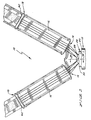
- Figure 1 shows a top plan view of an apparatus for simultaneously forming two continuous dough sheets from a single cooker extruder according to the preferred teachings of the present invention.
- Figure 2 shows a side elevational view of the apparatus of Figure 1.
- Figure 3 shows a cross-sectional view of the apparatus of Figure 1 according to section line 3-3 of Figure 1.
- Figure 4 shows a cross-sectional view of the apparatus of Figure 1 according to section line 4-4 of Figure 3.
- Figure 5 shows a perspective view of the die of the cooker extruder of the apparatus of Figure 1.
- apparatus 10 of the preferred form generally includes a single extruder 12, first and second guides 14, first and second conveyors 16, and first and second sheeting devices 18.
- extruder 12 is a cooker extruder and can be of any standard type such as a twin-screw cooker extruder manufactured by Clextral, Buehler, APV Baker, or Werner & Pfleiderer.
- Twin-screw cooker extruders 12 include a die head 20 having first and second, converging passages 22 that combine dough from both screw flows and then redistributes the dough evenly to a die 24. Specifically, passages 22 converge into a single opening located inside of die head 20. A funnel-shaped distribution cavity 23 extends from the face of die head 20 adjacent die 24 and intersects with the intersection opening of passages 22, with distribution cavity 23 having a circular cross-section at the face of die head 20 of a diameter and size a multiple of the diameter and size of passages 22 and their intersection opening. Experience shows that more uniform products are produced using the converging passages 22 that combine dough from both screw flows.
- die 24 is of an improved design for extruding first and second groups of a plurality of uniform and consistent ropes of dough at a non-parallel angle to each other.
- die 24 includes first and second die plates 26 of equal size and having their front side edges integrally interconnected at an obtuse angle in the order of 120° in the preferred form.
- Triangular-shaped, top and bottom closure plates 28 are integrally connected to the top and bottom edges of plates 26, respectively, with plates 28 extending generally perpendicular to plates 26.
- the back edges of plates 26 and 28 are integrally interconnected to an annular connection plate 30, with connection plate 30 having a cylindrical periphery in the preferred form.
- Plates 26 extend at an acute angle from plate 30 in the order of 30° in the preferred form while plates 28 extend generally perpendicular to plate 30.
- Die 24 can be attached to head 20 by any suitable manner such as counterbored bores 32 extending through plate 30 radially outside of plates 26 and 28 (with 8 bores 32 shown) for receipt of bolts 34 threadably received in head 20.
- Plates 26 have constant thickness and are each generally square in shape having lengths along an edge generally equal to one-half the diameter of cavity 23 at the face of die head 20, with plates 26 and 28 being generally centered in cavity 23.
- the spacing between the back edges of plates 26 is generally equal to the diameter of cavity 23 at the face of die head 20 and preferably slightly smaller.
- the intersection opening of passages 22 is generally parallel to the front and back edges of plates 26 and perpendicular to the top and bottom edges of plates 26.
- Each of plates 26 includes a plurality of parallel, extrusion apertures 36 shown as four in the preferred form arranged in a top pair of apertures 36a and 36b in the same horizontal plane arranged over a bottom pair of apertures 36c and 36d in the same horizontal plane, with the first extrusion apertures 36a and 36c of each pair being in the same vertical plane and spaced from the front edges an equal distance and the second extrusion apertures 36b and 36d of each pair being in the same vertical plane and spaced from the front edges an equal distance greater than the spacing of the first extrusion apertures 36a and 36c of each pair from the front edges.
- the spacing between the centers of apertures 36a and 36b and between apertures 36c and 36d is generally equal to the spacing between the centers of the top and bottom pairs of apertures 36a and 36b and 36c and 36d, respectively, and in the most preferred form the spacing between the centers of the top and bottom pairs of apertures 36a and 36b and 36c and 36d, respectively, being slightly less than the spacing between the centers of apertures 36a and 36b and of apertures 36c and 36d in each pair.
- the centers of the top pairs of apertures 36a and 36b are spaced from the top edges and the centers of the bottom pairs of apertures 36c and 36d are spaced from the bottom edges of plates 26 the same distance which is less than one-half the spacing between the pairs of apertures 36a and 36b and apertures 36c and 36d.
- the centers of the first apertures 36a and 36c of each pair of plates 26 are spaced from the front edges of plates 26 a distance substantially greater than the centers of the second apertures 36b and 36d of each pair of plates 26 are spaced from the back edges of plates 26.
- extrusion apertures 36 extend generally perpendicular to the inner and outer faces of die plates 26.
- Each of apertures 36 have a generally circular cross-section including a first portion 38 of a generally constant cross-section and extending from the outer face of plates 26 for approximately 10% of the thickness of plates 26 and a second portion 40 extending from first portion 38 to the inner face of plates 26 and of an expanding cross-section and particularly expanding at an angle of 5° from portion 38.
- Sheeting devices 18 each include first and second horizontally arranged pressing rollers 42 which abut together and are rotated in opposite directions.
- Conveyors 16 extend at an upward incline above pressing rollers 42 with the dough ropes falling vertically by gravity from conveyors 16 to the nip of pressing rollers 42.
- Sheets formed by pressing rollers 42 extend vertically downward by gravity onto a conveyor which conveys the sheets to the next processing step.
- Guides 14 are shown in the most preferred form as guide posts 44 equal in number to the number of apertures 36 in each die plate 26 (with four shown in the preferred form) mounted to the frame of each conveyor 16 opposite sheeting device 18. Guide posts 44 are generally equally spaced along the width of each conveyor 16. In the preferred form, guide posts 44 are formed of heat-resistant plastic that doesn't deform such as DELRINTM made by Dupont.
- extrudate in the form of dough is extruded from cooker extruder 12 through passages 22 and which combines in distribution cavity 23. From cavity 23, the dough flows into the roof-shaped extension formed by plates 26 and 28 of die 24 which is in fluid communication and extends outwardly from distribution cavity 23. The dough then flows from the roof-shaped extension initially into second portions 40 and then through first portions 38 of each of the four apertures 36 in both plates 26. It can then be appreciated that the dough forced through apertures 36 is extruded in the form of first and second groups of four continuous ropes which extend generally parallel to each other in each group but with the groups extending in two different directions at a non-parallel angle in the order of 60° in the preferred form from each plate 26.
- the first and second groups of dough ropes extruded from the first and second die plates 26 simultaneously extend to guide posts 44 of the first and second guides 14, respectively, where the ropes of dough simultaneously pass around guide posts 44 and are guided onto the first and second conveyors 16, respectively.
- the ropes of dough are then simultaneously conveyed on conveyors 16 to the respective sheeting devices 18 where they simultaneously pass between press rollers 42 and are formed into first and second sheets.
- Guide posts 44 ensure positioning of the ropes of dough on conveyor 16 at equally spaced intervals so that the dough is distributed evenly over the full width of press rollers 42 after it passes through sheeting devices 18.
- apparatus 10 allows for the simultaneous formation of two continuous dough sheets from a single cooker extruder 12.
- the ropes of dough for each of the dough sheets are simultaneously extruded from cooker extruder 12 at a non-parallel angle (60° in the preferred form) so that operational failure of the formation of one sheet does not detrimentally affect the formation of the other sheet.
- a dough rope for one of the sheets may become entangled with the other ropes being extruded through the same plate 26 forming that sheet as is common in current apparatus but is unlikely to become entangled in the ropes forming the other sheet being extruded through apertures 36 of the other plate 26.
- die 24 extrudes dough ropes at uniform and consistent flows.
- die plates 26 and apertures 36 of the preferred form are arranged in a manner which are particularly advantageous.
- apertures 36 of die plates 26 are of the same length, which is equal to the thickness of die plates 26 since apertures 36 extend generally perpendicular to the inner and outer faces of die plates 26. It should be recognized that the length of the extrusion apertures is important in that the longer the flow path from cooker extruder 12 to the outside face of the die, more resistance to flow and less control of that flow exists producing nonuniformity.
- the equal length of apertures 36, the arrangement of apertures 36 in each of plates 26, and the arrangement of plates 26 relative to each other insures that there is an equal pressure drop through apertures 36, with apertures 36 being generally equally spaced from the center of dough flow, to produce uniform and consistent dough ropes and without the necessity of adjustment valves which add to the cost and complexity of the apparatus and which also can have a negative impact on the consistency of the dough.
- the uniformity and consistency of the dough is more of a problem in the production of snack products of the present invention than in other food production fields such as graham crackers where the dough is cooked to a greater degree and tends to be dryer and sheeted in thicker sheets.
- apparatus 10 of the present invention can be quickly converted to be of the type of prior apparatus.
- die 24 can be replaced with a prior die for extruding four dough ropes which are guided by the first guide 14 onto the first conveyor 16 and into first sheeting device 18, with the second guide 14, second conveyor 16, and second sheeting device 18 being idled until it is again desired to simultaneously form two dough sheets.
Landscapes
- Engineering & Computer Science (AREA)
- Life Sciences & Earth Sciences (AREA)
- Food Science & Technology (AREA)
- Chemical & Material Sciences (AREA)
- Polymers & Plastics (AREA)
- Manufacturing & Machinery (AREA)
- Health & Medical Sciences (AREA)
- Nutrition Science (AREA)
- Extrusion Moulding Of Plastics Or The Like (AREA)
- Manufacturing And Processing Devices For Dough (AREA)
- Confectionery (AREA)
Abstract
Description
- The present invention generally relates to apparatus and methods for forming first and second, continuous, independent, extrudates, and particularly to apparatus and methods for simultaneously forming two dough sheets from a single cooker extruder for the preparation of a snack product by conventional deep fat frying.
- One type of snack product which has gained wide market acceptance is the "puffed" snack product. In certain methods of preparation, a cooked farinaceous dough is formed into a single continuous dough sheet. This dough sheet is then run through a piece forming apparatus which includes an opposed pair of rollers at least one of which has depressions which stamp out the desired shape and size pieces from the dough sheet. After formation of the dough pieces, the pieces are dried under controlled conditions from a moisture content of about 18% down to a moisture content of between 10% and 15% to form a half product or pellet. The moisture content of the half product is sufficiently low to exhibit extended shelf stability. The snack product is prepared from the half product by conventional deep fat frying. The frying of the half product generates steam volumes inside of the half product to puff the half product resulting in a light, puffed snack product having surface corrugations.
- The sale of snack food products is a highly competitive business. The novelty of snack food products decline rapidly, as new and different types of snack foods are introduced to maintain or increase market share. Puffed snack products can be varied in various ways such as by changing the shapes, sizes, and surface corrugations of the pieces or by changing the composition of the dough from which the half products are prepared. Another variation is to have the puffed snack product of a hollow structure, with the hollow configuration resulting from the fabrication of the half products from a two-layer laminated dough sheet. One method of forming a laminated dough sheet is to fold a single continuous dough sheet into a two-plied dough sheet as set forth in U.S. application No. 699,039 filed May 13, 1991, now U.S. Patent No. 5,092,757.
- The continuous dough sheet is often formed by passing a plurality (such as 4) of spaced ropes of dough between sheet pressing rollers. The spaced ropes of dough are extruded from a cooker extruder onto a conveyor which delivers the ropes of dough to the sheet pressing rollers. Generally, the dough ropes are formed by forcing the dough through a die plate including extrusion apertures. The formation of the dough sheet from a plurality of spaced ropes rather than passing a single amount of dough between the sheet pressing rollers forms a more uniform sheet resulting in more uniform half product pieces and more uniform puffed snack pieces. Additionally, the formation of the dough sheet from a plurality of spaced ropes rather than passing a single amount of dough between the sheet pressing rollers better dissipates heat along the sheet pressing rollers. However, the formation of such a dough sheet continuously from a plurality of dough ropes presents many problems. In particular, it should be appreciated that the ropes of dough have to be generally uniformly spaced on the conveyor and into the sheet pressing rollers. Further, a common problem is that the dough ropes will break causing the ropes of dough to fall on the floor and/or become entangled with each other. Further, the cooker extruder is a relatively expensive piece of equipment which has the capacity to supply ropes of dough for more than one sheet and in fact the consistency of the dough produced by the cooker extruder may in fact increase with the production of dough for more than one sheet from the same cooker extruder. However, it can be appreciated that additional problems arise from attempting to simultaneously extrude dough ropes for two dough sheets. Particularly, in addition to preventing consistent production for one sheet, breakage of one or more dough ropes for one of the sheets may detrimentally effect the consistent production of the other sheet, for example, the ropes of dough for one sheet becoming entangled in the ropes of dough for the other sheet. Further, factors such as unequal pressure drop through the respective die channels, the length of the channels, and the like affect the uniformity and consistency of the dough ropes which in turn affect the uniformity and consistency of the dough sheet, the half products, and the puffed snack products.
- Accordingly, it is an object of the present invention to provide novel apparatus and methods for the simultaneous formation of two continuous dough sheets from a single cooker extruder.
- Another object of the present invention is to provide such novel apparatus and methods where the ropes of dough extruded from the cooker extruder are directed at a non-parallel angle to reduce operational failure of the formation of one sheet from detrimentally affecting the formation of the other sheet.
- Yet another object of the present invention is to provide such novel apparatus and methods where the ropes of dough are uniformly and consistently extruded.
- GB-A-2 072 482 discloses a die for use with a single extruder for extruding extrudate including a die head having a distribution cavity. The die is attached to the die head and includes a plurality of extrusion apertures through which the extrudate flows.
- The present invention solves this need and the problems and disadvantages of the prior apparatus and methods and is characterized in that the die comprises first and second die plates, with each of the die plates having front and back edges and being of a constant thickness, with the die plates being integrally connected about their front edges at an obtuse angle relative to each other, with the attaching means attaching the first and second die plates to the die head with the first and second die plates forming a cavity extension in fluid communication with and extending outwardly from the distribution cavity of the die head, with the plurality of extrusion apertures extending through each of the first and second die plates spaced from the front and back edges and through which the extrudate flows from the cavity extension.
- Further, the present invention is characterized in that the extrudate is simultaneously extruded in the form of ropes and in first and second groups, with each of the groups including a plurality of extrudate ropes, with the first and second groups of extrudate ropes extending at a non-parallel angle relative to each other and in the order to prevent operational failure of the extrusion of one of the first and second groups from detrimentally affecting the extrusion of the other of the first and second groups, with the extrudate ropes of the first group being guided onto a first conveyor at equally spaced intervals on the first conveyor and the extrudate ropes of the second group being simultaneously guided onto a second conveyor at equally spaced intervals on the second conveyor, with the extrudate ropes of the first and second groups being simultaneously conveyed on the first and second conveyors, and with the extrudate ropes of the first group being pressed into a first sheet and the extrudate ropes of the second group being simultaneously pressed into a second sheet.
- Surprisingly, the above objectives can be satisfied in the field of puffed snack product fabrication by providing, in the preferred form, apparatus and methods of forming first and second continuous dough sheets from a single cooker extruder where first and second groups of a plurality of dough ropes are simultaneously extruded at a non-parallel angle to prevent entanglement of the dough ropes of one group with the dough ropes of the other group and are simultaneously guided at equally spaced intervals onto respective conveyors where the dough ropes are conveyed to respective sheeting devices and sheeted into first and second dough sheets.
- In a preferred aspect of the present invention, a die for the cooker extruder is provided including first and second die plates integrally connected by their front edges at an obtuse angle, with each of the die plates including a plurality of extrusion apertures corresponding to the number of dough ropes in each group and through which the dough is extruded from the cooker extruder.
- The present invention will become clearer in light of the following detailed description of an illustrative embodiment of this invention described in connection with the drawings.
- Figure 1 shows a top plan view of an apparatus for simultaneously forming two continuous dough sheets from a single cooker extruder according to the preferred teachings of the present invention.
- Figure 2 shows a side elevational view of the apparatus of Figure 1.
- Figure 3 shows a cross-sectional view of the apparatus of Figure 1 according to section line 3-3 of Figure 1.
- Figure 4 shows a cross-sectional view of the apparatus of Figure 1 according to section line 4-4 of Figure 3.
- Figure 5 shows a perspective view of the die of the cooker extruder of the apparatus of Figure 1.
- All figures are drawn for ease of explanation of the basic teachings of the present invention only; the extensions of the Figures with respect to number, position, relationship, and dimensions of the parts to form the preferred embodiment will be explained or will be within the skill of the art after the following teachings of the present invention have been read and understood. Further, the exact dimensions and dimensional proportions to conform to specific force, weight, strength, and similar requirements will likewise be within the skill of the art after the following teachings of the present invention have been read and understood.
- Where used in the various figures of the drawings, the same numerals designate the same or similar parts. Furthermore, when the terms "first", "second", "lower", "upper", "end", "face", "edge", "front", "back", "top", "bottom", and similar terms are used herein, it should be understood that these terms have reference only to the structure shown in the drawings as it would appear to a person viewing the drawings and are utilized only to facilitate describing the invention.
- Referring now to the drawings and in particular to Figures 1 and 2, an apparatus utilizing the present methods for forming first and second sheets according to the preferred teachings of the present invention is shown and generally designated 10. Particularly,
apparatus 10 of the preferred form generally includes asingle extruder 12, first andsecond guides 14, first andsecond conveyors 16, and first andsecond sheeting devices 18. In the preferred form where the extrudate is in the form of dough,extruder 12 is a cooker extruder and can be of any standard type such as a twin-screw cooker extruder manufactured by Clextral, Buehler, APV Baker, or Werner & Pfleiderer. Twin-screw cooker extruders 12 include a diehead 20 having first and second, convergingpassages 22 that combine dough from both screw flows and then redistributes the dough evenly to a die 24. Specifically,passages 22 converge into a single opening located inside of diehead 20. A funnel-shaped distribution cavity 23 extends from the face of diehead 20adjacent die 24 and intersects with the intersection opening ofpassages 22, withdistribution cavity 23 having a circular cross-section at the face of diehead 20 of a diameter and size a multiple of the diameter and size ofpassages 22 and their intersection opening. Experience shows that more uniform products are produced using theconverging passages 22 that combine dough from both screw flows. - According to the teachings of the present invention, die 24 is of an improved design for extruding first and second groups of a plurality of uniform and consistent ropes of dough at a non-parallel angle to each other. Specifically, die 24 includes first and
second die plates 26 of equal size and having their front side edges integrally interconnected at an obtuse angle in the order of 120° in the preferred form. Triangular-shaped, top andbottom closure plates 28 are integrally connected to the top and bottom edges ofplates 26, respectively, withplates 28 extending generally perpendicular toplates 26. The back edges ofplates annular connection plate 30, withconnection plate 30 having a cylindrical periphery in the preferred form.Plates 26 extend at an acute angle fromplate 30 in the order of 30° in the preferred form whileplates 28 extend generally perpendicular toplate 30. Die 24 can be attached tohead 20 by any suitable manner such ascounterbored bores 32 extending throughplate 30 radially outside ofplates 26 and 28 (with 8bores 32 shown) for receipt ofbolts 34 threadably received inhead 20.Plates 26 have constant thickness and are each generally square in shape having lengths along an edge generally equal to one-half the diameter ofcavity 23 at the face of diehead 20, withplates cavity 23. The spacing between the back edges ofplates 26 is generally equal to the diameter ofcavity 23 at the face of diehead 20 and preferably slightly smaller. In the preferred form, the intersection opening ofpassages 22 is generally parallel to the front and back edges ofplates 26 and perpendicular to the top and bottom edges ofplates 26. - Each of
plates 26 includes a plurality of parallel,extrusion apertures 36 shown as four in the preferred form arranged in a top pair ofapertures apertures first extrusion apertures second extrusion apertures first extrusion apertures apertures apertures apertures apertures apertures apertures apertures apertures plates 26 the same distance which is less than one-half the spacing between the pairs ofapertures apertures first apertures plates 26 are spaced from the front edges of plates 26 a distance substantially greater than the centers of thesecond apertures plates 26 are spaced from the back edges ofplates 26. - The centers of
extrusion apertures 36 extend generally perpendicular to the inner and outer faces ofdie plates 26. Each ofapertures 36 have a generally circular cross-section including afirst portion 38 of a generally constant cross-section and extending from the outer face ofplates 26 for approximately 10% of the thickness ofplates 26 and asecond portion 40 extending fromfirst portion 38 to the inner face ofplates 26 and of an expanding cross-section and particularly expanding at an angle of 5° fromportion 38. -
Sheeting devices 18 each include first and second horizontally arrangedpressing rollers 42 which abut together and are rotated in opposite directions.Conveyors 16 extend at an upward incline above pressingrollers 42 with the dough ropes falling vertically by gravity fromconveyors 16 to the nip of pressingrollers 42. Sheets formed by pressingrollers 42 extend vertically downward by gravity onto a conveyor which conveys the sheets to the next processing step. -
Guides 14 are shown in the most preferred form as guide posts 44 equal in number to the number ofapertures 36 in each die plate 26 (with four shown in the preferred form) mounted to the frame of eachconveyor 16opposite sheeting device 18. Guide posts 44 are generally equally spaced along the width of eachconveyor 16. In the preferred form, guide posts 44 are formed of heat-resistant plastic that doesn't deform such as DELRIN™ made by Dupont. - In operation, extrudate in the form of dough is extruded from
cooker extruder 12 throughpassages 22 and which combines indistribution cavity 23. Fromcavity 23, the dough flows into the roof-shaped extension formed byplates die 24 which is in fluid communication and extends outwardly fromdistribution cavity 23. The dough then flows from the roof-shaped extension initially intosecond portions 40 and then throughfirst portions 38 of each of the fourapertures 36 in bothplates 26. It can then be appreciated that the dough forced throughapertures 36 is extruded in the form of first and second groups of four continuous ropes which extend generally parallel to each other in each group but with the groups extending in two different directions at a non-parallel angle in the order of 60° in the preferred form from eachplate 26. The first and second groups of dough ropes extruded from the first andsecond die plates 26 simultaneously extend to guideposts 44 of the first andsecond guides 14, respectively, where the ropes of dough simultaneously pass aroundguide posts 44 and are guided onto the first andsecond conveyors 16, respectively. The ropes of dough are then simultaneously conveyed onconveyors 16 to therespective sheeting devices 18 where they simultaneously pass betweenpress rollers 42 and are formed into first and second sheets. Guide posts 44 ensure positioning of the ropes of dough onconveyor 16 at equally spaced intervals so that the dough is distributed evenly over the full width ofpress rollers 42 after it passes throughsheeting devices 18. - It can then be appreciated that
apparatus 10 according to the preferred teachings of the present invention allows for the simultaneous formation of two continuous dough sheets from asingle cooker extruder 12. It should further be noted that the ropes of dough for each of the dough sheets are simultaneously extruded fromcooker extruder 12 at a non-parallel angle (60° in the preferred form) so that operational failure of the formation of one sheet does not detrimentally affect the formation of the other sheet. For example, a dough rope for one of the sheets may become entangled with the other ropes being extruded through thesame plate 26 forming that sheet as is common in current apparatus but is unlikely to become entangled in the ropes forming the other sheet being extruded throughapertures 36 of theother plate 26. Thus, a disturbance in the formation of one sheet no longer influences the formation of the other sheet. Further, the non-parallel angle of the groups of dough ropes allow the physical placement ofconveyors 16, guide posts 44, andsheeting devices 18 at the same level and adjacent to each other. - Also, die 24 according to the teachings of the present invention extrudes dough ropes at uniform and consistent flows. Specifically, die
plates 26 andapertures 36 of the preferred form are arranged in a manner which are particularly advantageous. Specifically,apertures 36 ofdie plates 26 are of the same length, which is equal to the thickness ofdie plates 26 sinceapertures 36 extend generally perpendicular to the inner and outer faces ofdie plates 26. It should be recognized that the length of the extrusion apertures is important in that the longer the flow path fromcooker extruder 12 to the outside face of the die, more resistance to flow and less control of that flow exists producing nonuniformity. It should further be appreciated that the equal length ofapertures 36, the arrangement ofapertures 36 in each ofplates 26, and the arrangement ofplates 26 relative to each other insures that there is an equal pressure drop throughapertures 36, withapertures 36 being generally equally spaced from the center of dough flow, to produce uniform and consistent dough ropes and without the necessity of adjustment valves which add to the cost and complexity of the apparatus and which also can have a negative impact on the consistency of the dough. It should be further noted that the uniformity and consistency of the dough is more of a problem in the production of snack products of the present invention than in other food production fields such as graham crackers where the dough is cooked to a greater degree and tends to be dryer and sheeted in thicker sheets. - It should also be noted that if it is desired to form a single dough sheet from
cooker extruder 12,apparatus 10 of the present invention can be quickly converted to be of the type of prior apparatus. Specifically, die 24 can be replaced with a prior die for extruding four dough ropes which are guided by thefirst guide 14 onto thefirst conveyor 16 and intofirst sheeting device 18, with thesecond guide 14,second conveyor 16, andsecond sheeting device 18 being idled until it is again desired to simultaneously form two dough sheets. - Thus since the invention disclosed herein may be embodied in other specific forms without departing from the general characteristics thereof, some of which forms have been indicated, the embodiments described herein are to be considered in all respects illustrative and not restrictive. The scope of the invention is to be indicated by the appended claims, rather than by the foregoing description, and all changes which come within the meaning and range of equivalency of the claims are intended to be embraced therein.
Claims (15)
- A die (24) for use with a single extruder (12) for extruding extrudate including a die head (20) having a distribution cavity (23), with the die (24) including a plurality of extrusion apertures (36) through which the extrudate flows and means (30, 32, 34) for attaching the die (24) to the die head (20), characterized in that the die (24) comprises first and second die plates (26), with each of the die plates (26) having front and back edges and being of a constant thickness, with the die plates (26) being integrally connected about their front edges at an obtuse angle relative to each other, with the attaching means (30, 32, 34) attaching the first and second die plates (26) to the die head (20) with the first and second die plates (26) forming a cavity extension in fluid communication with and extending outwardly from the distribution cavity (23) of the die head (20), with the plurality of extrusion apertures (36) extending through each of the first and second die plates (26) spaced from the front and back edges and through which the extrudate flows from the cavity extension.
- The die of claim 1 wherein the attaching means comprises, in combination: an annular connection plate (30), with the back edges of the first and second die plates (26) being connected to the connection plate (30) with the first and second die plates (26) extending at an acute angle from the connection plate (30); and means (32, 34) for attaching the connection plate (30) to the die head (20).
- The die of claim 2 further comprising, in combination: first and second, triangular-shaped, top and bottom closure plates (28) connected to the top and bottom edges of the first and second die plates (26) and to the connection plate (30) generally perpendicular thereto.
- The die of any preceding claim wherein first, second, third, and fourth extrusion apertures (36) are located in each of the first and second die plates (26), with the first and second extrusion apertures (36) being spaced from the front edges an equal distance, with the third and fourth extrusion apertures (36) being spaced from the front edges an equal distance, with the first and third and the second and fourth extrusion apertures (36) being spaced from each other an equal distance.
- The die of claim 4 wherein the first and second extrusion apertures (36) are spaced from the front edges a distance substantially greater than the third and fourth extrusion apertures (36) are spaced from the back edges of the die plates (26).
- The die of claim 5 wherein the first and third extrusion apertures (36) are spaced from the top edges of the first and second die plates (26) a distance generally equal to the spacing of the second and fourth extrusion apertures (36) from the bottom edges of the first and second die plates (26) and which is less than one-half of the spacing between the first and second extrusion apertures (36).
- The die of any preceding claim wherein the centers of the extrusion apertures (36) extend generally perpendicular to the inner and outer faces of the first and second die plates (26).
- The die of any preceding claim wherein each of the extrusion apertures (36) comprises a first portion (38) of a generally constant cross-section extending from the outer face part way through the thickness of the die plates (26) and a second portion (40) extending from the first portion to the inner face of the die plates (26) of an expanding cross-section.
- The die of any preceding claim further comprising, in combination: first and second sheeting devices (18); first means (14, 16) for guiding the extrudate extruded through the extrusion apertures (36) of the first die plate (26) to the first sheeting device (18) at equally spaced intervals; and second means (14, 16) for guiding the extrudate extruded through the extrusion apertures (36) of the second die plate (26) to the second sheeting device (18) at equally spaced intervals, with the first and second sheeting devices (18) simultaneously forming two sheets.
- The die of claim 9 wherein the guiding means each include a conveyor (16) for conveying the extrudate to the sheeting device (18) and guide posts (14) mounted to the conveyor (16) opposite the sheeting device (18) for guiding the extrudate from the die plate (26) to the conveyor (16).
- Method for simultaneously forming two sheets from extrudate including the steps of: simultaneously extruding multiple extrudates from a single extruder (12), characterized in that the extrudate is simultaneously extruded in the form of ropes and in first and second groups, with each of the groups including a plurality of extrudate ropes, with the first and second groups of extrudate ropes extending at a non-parallel angle relative to each other in order to prevent operational failure of the extrusion of one of the first or second groups from detrimentally affecting the extrusion of the other of the first and second groups; simultaneously guiding the extrudate ropes of the first group onto a first conveyor (16) at equally spaced intervals on the first conveyor (16) and guiding the extrudate ropes of the second group onto a second conveyor (16) at equally spaced intervals on the second conveyor (16); simultaneously conveying the extrudate ropes of the first and second groups on the first and second conveyors (16); and simultaneously pressing the extrudate ropes of the first group into a first sheet and pressing the extrudate ropes of the second group into a second sheet.
- The method of claim 11 wherein the extruding step comprises the step of extruding the extrudate ropes parallel to each other in the first and second groups and with the non-parallel angle of the first and second groups being in the order of 60°.
- The method of claim 11 or 12 wherein the extruding step comprises the step of extruding first and second groups of first, second, third, and fourth extrudate ropes, with the first and third and the second and fourth extrudate ropes being in the same vertical planes and the first and third and the second and fourth being in the same horizontal planes.
- The method of any preceding claim 11-13 wherein the extruding step comprises the steps of: providing a die (24) on the single extruder (12), with the die (24) comprising, in combination: first and second die plates (26), with each of the die plates (26) having front and back edges and being of a constant thickness, with the die plates (26) being integrally connected about their front edges at an obtuse angle relative to each other and forming a cavity extension, and a plurality of extrusion apertures (36) extending through each of the first and second die plates (26) spaced from the front and back edges and through which the extrudate flows from the cavity extension; and simultaneously extruding the extrudate through the extrusion apertures (36) of the first and second die plates (26).
- The method of any preceding claim 11-14 wherein the guiding step comprises the steps of: providing a plurality of guide posts (14) mounted to the conveyor (16); and passing one of the extrudate ropes around one of the guide posts (14) and onto the conveyor (16).
Applications Claiming Priority (3)
| Application Number | Priority Date | Filing Date | Title |
|---|---|---|---|
| US07/886,913 US5223296A (en) | 1992-05-22 | 1992-05-22 | Apparatus and methods for forming extrudates |
| US886913 | 1992-05-22 | ||
| PCT/US1993/004423 WO1993024014A1 (en) | 1992-05-22 | 1993-05-10 | Apparatus and methods for forming extrudates |
Publications (2)
| Publication Number | Publication Date |
|---|---|
| EP0635999A1 EP0635999A1 (en) | 1995-02-01 |
| EP0635999B1 true EP0635999B1 (en) | 1996-11-06 |
Family
ID=25390067
Family Applications (1)
| Application Number | Title | Priority Date | Filing Date |
|---|---|---|---|
| EP93911219A Expired - Lifetime EP0635999B1 (en) | 1992-05-22 | 1993-05-10 | Apparatus and method for forming extrudates |
Country Status (12)
| Country | Link |
|---|---|
| US (1) | US5223296A (en) |
| EP (1) | EP0635999B1 (en) |
| JP (1) | JPH07507212A (en) |
| KR (1) | KR100275434B1 (en) |
| AU (1) | AU4242893A (en) |
| BR (1) | BR9306396A (en) |
| CA (1) | CA2136344A1 (en) |
| DE (1) | DE69305842T2 (en) |
| ES (1) | ES2096293T3 (en) |
| GR (1) | GR3022479T3 (en) |
| MX (1) | MX9303012A (en) |
| WO (1) | WO1993024014A1 (en) |
Families Citing this family (4)
| Publication number | Priority date | Publication date | Assignee | Title |
|---|---|---|---|---|
| US8926308B2 (en) | 2010-04-21 | 2015-01-06 | Intercontinental Great Brands Llc | Dough extruders and methods |
| AT513947A1 (en) * | 2013-01-15 | 2014-08-15 | Haas Food Equipment Gmbh | Apparatus and method for forming elongated, belt-shaped bodies and for the production of bakery products |
| US9908275B2 (en) | 2015-08-10 | 2018-03-06 | Wenger Manufacturing, Inc. | High capacity dual die assembly |
| WO2018137744A1 (en) * | 2017-01-27 | 2018-08-02 | Biomar Group A/S | Nozzle for an extruder |
Family Cites Families (18)
| Publication number | Priority date | Publication date | Assignee | Title |
|---|---|---|---|---|
| US3061440A (en) * | 1961-03-08 | 1962-10-30 | Campbell Soup Co | Process for making spaghetti |
| US3340572A (en) * | 1966-01-05 | 1967-09-12 | Rexall Drug Chemical | Multi-strand extruding die |
| US3551165A (en) * | 1967-11-08 | 1970-12-29 | Stanley Hamilton Reesman | Process for producing shaped dough pieces and apparatus |
| US3586517A (en) * | 1969-04-01 | 1971-06-22 | Beatrice Foods Co | Extruder die |
| AU441562B2 (en) * | 1970-08-31 | 1973-10-17 | Nabisco Brands Incorporated | Food processing method and apparatus |
| US3847531A (en) * | 1973-08-29 | 1974-11-12 | K Mccomb | Die assembly for foodstuff extruder |
| FR2383771A1 (en) * | 1977-03-16 | 1978-10-13 | Diepal | EXTRUSION TIP |
| DE2934077A1 (en) * | 1979-08-23 | 1981-03-26 | Hebenstreit GmbH, 64546 Mörfelden-Walldorf | METHOD AND DEVICE FOR PRODUCING BLOCK-SHAPED FOOD PRODUCTS |
| IT8021170V0 (en) * | 1980-03-14 | 1980-03-14 | Cavalli Alfredo | DRAWER OF THE PERFECT TYPE FOR THE PRODUCTION OF THE DIFFERENT FRESH FOOD PASTA FORMATS. |
| IT1129467B (en) * | 1980-12-19 | 1986-06-04 | Lavorazione Mat Plast | ADAPTER FOR SIMULTANEOUS EXTRUSION OF MULTIPLE THREADS OF SYNTHETIC THERMOPLASTIC FOAM USING A SINGLE EXTRUDER |
| US4383817A (en) * | 1982-02-11 | 1983-05-17 | E. I. Du Pont De Nemours And Company | Spinneret plate |
| US4567051A (en) * | 1982-11-04 | 1986-01-28 | Frito-Lay, Inc. | Method for producing snacks from dough |
| US4557940A (en) * | 1982-11-15 | 1985-12-10 | Jac Creative Foods, Inc. | Fish slurry processing method |
| US4445838A (en) * | 1982-12-27 | 1984-05-01 | Groff Edwin T | Apparatus for extruding a comestible |
| US4614489A (en) * | 1985-01-07 | 1986-09-30 | Star-Kist Foods, Inc. | Simultaneous extrusion of multiple streams of a fibrous food product |
| DK8603160A (en) * | 1986-07-11 | 1988-01-04 | ||
| US4790996A (en) * | 1987-06-10 | 1988-12-13 | General Foods Corporation | Process for preparing cereal products |
| US5092757A (en) * | 1991-05-13 | 1992-03-03 | General Mills, Inc. | Apparatus for flipping and aligning a dough sheet |
-
1992
- 1992-05-22 US US07/886,913 patent/US5223296A/en not_active Expired - Fee Related
-
1993
- 1993-05-10 EP EP93911219A patent/EP0635999B1/en not_active Expired - Lifetime
- 1993-05-10 KR KR1019940704202A patent/KR100275434B1/en not_active Expired - Fee Related
- 1993-05-10 CA CA002136344A patent/CA2136344A1/en not_active Abandoned
- 1993-05-10 JP JP6500568A patent/JPH07507212A/en active Pending
- 1993-05-10 AU AU42428/93A patent/AU4242893A/en not_active Abandoned
- 1993-05-10 ES ES93911219T patent/ES2096293T3/en not_active Expired - Lifetime
- 1993-05-10 BR BR9306396A patent/BR9306396A/en not_active IP Right Cessation
- 1993-05-10 DE DE69305842T patent/DE69305842T2/en not_active Expired - Fee Related
- 1993-05-10 WO PCT/US1993/004423 patent/WO1993024014A1/en not_active Ceased
- 1993-05-21 MX MX9303012A patent/MX9303012A/en unknown
-
1997
- 1997-02-05 GR GR970400181T patent/GR3022479T3/en unknown
Also Published As
| Publication number | Publication date |
|---|---|
| MX9303012A (en) | 1994-01-31 |
| JPH07507212A (en) | 1995-08-10 |
| CA2136344A1 (en) | 1993-12-09 |
| GR3022479T3 (en) | 1997-05-31 |
| WO1993024014A1 (en) | 1993-12-09 |
| AU4242893A (en) | 1993-12-30 |
| KR100275434B1 (en) | 2000-12-15 |
| ES2096293T3 (en) | 1997-03-01 |
| DE69305842T2 (en) | 1997-05-22 |
| US5223296A (en) | 1993-06-29 |
| DE69305842D1 (en) | 1996-12-12 |
| EP0635999A1 (en) | 1995-02-01 |
| BR9306396A (en) | 1995-05-02 |
Similar Documents
| Publication | Publication Date | Title |
|---|---|---|
| US8926308B2 (en) | Dough extruders and methods | |
| US4698004A (en) | Nozzle for extrusion | |
| US4322202A (en) | Dough extruder and sheet spreader apparatus | |
| US4888192A (en) | Method for extrusion of baked goods | |
| CA2535322C (en) | Method and apparatus for cutting a curly puff extrudate | |
| JP5844415B2 (en) | Die and related method for making extruded synthetic wood | |
| EP1221284A2 (en) | Food piece and apparatus and methods for making multiple, complexly patterned extrudates | |
| US5384142A (en) | Process for preparing textured dough products | |
| US5223296A (en) | Apparatus and methods for forming extrudates | |
| AU2003230656B2 (en) | Dimensional quality of direct-expanded food products | |
| US5167980A (en) | Horizontal extrusion of edge rippled snack product | |
| US6612825B2 (en) | Pillow cutting extruder machine | |
| CN111616178A (en) | Forming device for processing wheat flour fine dried noodles and using method thereof | |
| US10492499B2 (en) | Food product with filling | |
| CN209563409U (en) | A kind of potato packet production musculus cutaneus fillings mixing arrangement | |
| JPS63102660A (en) | Forming device for food |
Legal Events
| Date | Code | Title | Description |
|---|---|---|---|
| PUAI | Public reference made under article 153(3) epc to a published international application that has entered the european phase |
Free format text: ORIGINAL CODE: 0009012 |
|
| 17P | Request for examination filed |
Effective date: 19941117 |
|
| AK | Designated contracting states |
Kind code of ref document: A1 Designated state(s): BE DE ES FR GB GR IT NL PT |
|
| GRAG | Despatch of communication of intention to grant |
Free format text: ORIGINAL CODE: EPIDOS AGRA |
|
| 17Q | First examination report despatched |
Effective date: 19960123 |
|
| GRAH | Despatch of communication of intention to grant a patent |
Free format text: ORIGINAL CODE: EPIDOS IGRA |
|
| GRAH | Despatch of communication of intention to grant a patent |
Free format text: ORIGINAL CODE: EPIDOS IGRA |
|
| GRAA | (expected) grant |
Free format text: ORIGINAL CODE: 0009210 |
|
| AK | Designated contracting states |
Kind code of ref document: B1 Designated state(s): BE DE ES FR GB GR IT NL PT |
|
| REF | Corresponds to: |
Ref document number: 69305842 Country of ref document: DE Date of ref document: 19961212 |
|
| ITF | It: translation for a ep patent filed | ||
| REG | Reference to a national code |
Ref country code: ES Ref legal event code: FG2A Ref document number: 2096293 Country of ref document: ES Kind code of ref document: T3 |
|
| ET | Fr: translation filed | ||
| REG | Reference to a national code |
Ref country code: GR Ref legal event code: FG4A Free format text: 3022479 |
|
| PLBE | No opposition filed within time limit |
Free format text: ORIGINAL CODE: 0009261 |
|
| STAA | Information on the status of an ep patent application or granted ep patent |
Free format text: STATUS: NO OPPOSITION FILED WITHIN TIME LIMIT |
|
| 26N | No opposition filed | ||
| PGFP | Annual fee paid to national office [announced via postgrant information from national office to epo] |
Ref country code: FR Payment date: 20000419 Year of fee payment: 8 |
|
| PGFP | Annual fee paid to national office [announced via postgrant information from national office to epo] |
Ref country code: GB Payment date: 20000420 Year of fee payment: 8 Ref country code: DE Payment date: 20000420 Year of fee payment: 8 |
|
| PGFP | Annual fee paid to national office [announced via postgrant information from national office to epo] |
Ref country code: NL Payment date: 20000427 Year of fee payment: 8 |
|
| PGFP | Annual fee paid to national office [announced via postgrant information from national office to epo] |
Ref country code: PT Payment date: 20000509 Year of fee payment: 8 |
|
| PGFP | Annual fee paid to national office [announced via postgrant information from national office to epo] |
Ref country code: BE Payment date: 20000512 Year of fee payment: 8 |
|
| PGFP | Annual fee paid to national office [announced via postgrant information from national office to epo] |
Ref country code: GR Payment date: 20000531 Year of fee payment: 8 |
|
| PGFP | Annual fee paid to national office [announced via postgrant information from national office to epo] |
Ref country code: ES Payment date: 20000608 Year of fee payment: 8 |
|
| PG25 | Lapsed in a contracting state [announced via postgrant information from national office to epo] |
Ref country code: GB Free format text: LAPSE BECAUSE OF NON-PAYMENT OF DUE FEES Effective date: 20010510 |
|
| PG25 | Lapsed in a contracting state [announced via postgrant information from national office to epo] |
Ref country code: ES Free format text: LAPSE BECAUSE OF NON-PAYMENT OF DUE FEES Effective date: 20010511 |
|
| PG25 | Lapsed in a contracting state [announced via postgrant information from national office to epo] |
Ref country code: GR Free format text: LAPSE BECAUSE OF NON-PAYMENT OF DUE FEES Effective date: 20010531 Ref country code: BE Free format text: LAPSE BECAUSE OF NON-PAYMENT OF DUE FEES Effective date: 20010531 |
|
| BERE | Be: lapsed |
Owner name: GENERAL MILLS INC. Effective date: 20010531 |
|
| PG25 | Lapsed in a contracting state [announced via postgrant information from national office to epo] |
Ref country code: PT Free format text: LAPSE BECAUSE OF NON-PAYMENT OF DUE FEES Effective date: 20011130 |
|
| PG25 | Lapsed in a contracting state [announced via postgrant information from national office to epo] |
Ref country code: NL Free format text: LAPSE BECAUSE OF NON-PAYMENT OF DUE FEES Effective date: 20011201 |
|
| GBPC | Gb: european patent ceased through non-payment of renewal fee |
Effective date: 20010510 |
|
| PG25 | Lapsed in a contracting state [announced via postgrant information from national office to epo] |
Ref country code: FR Free format text: LAPSE BECAUSE OF NON-PAYMENT OF DUE FEES Effective date: 20020131 |
|
| NLV4 | Nl: lapsed or anulled due to non-payment of the annual fee |
Effective date: 20011201 |
|
| PG25 | Lapsed in a contracting state [announced via postgrant information from national office to epo] |
Ref country code: DE Free format text: LAPSE BECAUSE OF NON-PAYMENT OF DUE FEES Effective date: 20020301 |
|
| REG | Reference to a national code |
Ref country code: PT Ref legal event code: MM4A Free format text: LAPSE DUE TO NON-PAYMENT OF FEES Effective date: 20011130 |
|
| REG | Reference to a national code |
Ref country code: ES Ref legal event code: FD2A Effective date: 20030203 |
|
| PG25 | Lapsed in a contracting state [announced via postgrant information from national office to epo] |
Ref country code: IT Free format text: LAPSE BECAUSE OF NON-PAYMENT OF DUE FEES Effective date: 20050510 |