EP0635866B1 - Lamp inlead assembly having a formed foil arrangement - Google Patents
Lamp inlead assembly having a formed foil arrangement Download PDFInfo
- Publication number
- EP0635866B1 EP0635866B1 EP94304500A EP94304500A EP0635866B1 EP 0635866 B1 EP0635866 B1 EP 0635866B1 EP 94304500 A EP94304500 A EP 94304500A EP 94304500 A EP94304500 A EP 94304500A EP 0635866 B1 EP0635866 B1 EP 0635866B1
- Authority
- EP
- European Patent Office
- Prior art keywords
- lamp
- lead wire
- foil
- foil member
- assembly
- Prior art date
- Legal status (The legal status is an assumption and is not a legal conclusion. Google has not performed a legal analysis and makes no representation as to the accuracy of the status listed.)
- Expired - Lifetime
Links
- 239000011888 foil Substances 0.000 title claims description 100
- WABPQHHGFIMREM-UHFFFAOYSA-N lead(0) Chemical compound [Pb] WABPQHHGFIMREM-UHFFFAOYSA-N 0.000 claims description 33
- 230000000712 assembly Effects 0.000 claims description 13
- 238000000429 assembly Methods 0.000 claims description 13
- 238000010891 electric arc Methods 0.000 claims description 4
- 230000008878 coupling Effects 0.000 claims description 2
- 238000010168 coupling process Methods 0.000 claims description 2
- 238000005859 coupling reaction Methods 0.000 claims description 2
- 239000000463 material Substances 0.000 claims description 2
- 230000005284 excitation Effects 0.000 claims 1
- 238000004519 manufacturing process Methods 0.000 description 17
- 238000000034 method Methods 0.000 description 10
- 238000007789 sealing Methods 0.000 description 10
- 230000008569 process Effects 0.000 description 9
- ZOKXTWBITQBERF-UHFFFAOYSA-N Molybdenum Chemical compound [Mo] ZOKXTWBITQBERF-UHFFFAOYSA-N 0.000 description 5
- 229910052750 molybdenum Inorganic materials 0.000 description 5
- 239000011733 molybdenum Substances 0.000 description 5
- 238000013459 approach Methods 0.000 description 4
- 238000003780 insertion Methods 0.000 description 3
- 230000037431 insertion Effects 0.000 description 3
- 229910052751 metal Inorganic materials 0.000 description 3
- 239000002184 metal Substances 0.000 description 3
- 239000010453 quartz Substances 0.000 description 3
- VYPSYNLAJGMNEJ-UHFFFAOYSA-N silicon dioxide Inorganic materials O=[Si]=O VYPSYNLAJGMNEJ-UHFFFAOYSA-N 0.000 description 3
- 238000005219 brazing Methods 0.000 description 2
- 238000010276 construction Methods 0.000 description 2
- 238000003825 pressing Methods 0.000 description 2
- 238000003466 welding Methods 0.000 description 2
- 230000001154 acute effect Effects 0.000 description 1
- 230000006978 adaptation Effects 0.000 description 1
- 230000002411 adverse Effects 0.000 description 1
- 239000011248 coating agent Substances 0.000 description 1
- 238000000576 coating method Methods 0.000 description 1
- 239000004020 conductor Substances 0.000 description 1
- 238000013461 design Methods 0.000 description 1
- 229910052736 halogen Inorganic materials 0.000 description 1
- 150000002367 halogens Chemical class 0.000 description 1
- 238000012986 modification Methods 0.000 description 1
- 230000004048 modification Effects 0.000 description 1
- 230000005855 radiation Effects 0.000 description 1
- 230000009467 reduction Effects 0.000 description 1
- 238000009877 rendering Methods 0.000 description 1
- 238000007665 sagging Methods 0.000 description 1
- 238000005728 strengthening Methods 0.000 description 1
Images

Classifications
-
- H—ELECTRICITY
- H01—ELECTRIC ELEMENTS
- H01J—ELECTRIC DISCHARGE TUBES OR DISCHARGE LAMPS
- H01J5/00—Details relating to vessels or to leading-in conductors common to two or more basic types of discharge tubes or lamps
- H01J5/46—Leading-in conductors
-
- H—ELECTRICITY
- H01—ELECTRIC ELEMENTS
- H01J—ELECTRIC DISCHARGE TUBES OR DISCHARGE LAMPS
- H01J61/00—Gas-discharge or vapour-discharge lamps
- H01J61/02—Details
- H01J61/36—Seals between parts of vessels; Seals for leading-in conductors; Leading-in conductors
- H01J61/366—Seals for leading-in conductors
-
- H—ELECTRICITY
- H01—ELECTRIC ELEMENTS
- H01K—ELECTRIC INCANDESCENT LAMPS
- H01K1/00—Details
- H01K1/40—Leading-in conductors
Definitions
- This invention relates to a lamp inlead assembly having an improved formed molybdenum foil configuration. More particularly, this invention relates to such a lamp inlead assembly as exhibits improved stability characteristics that allow for implementation in a high speed automated manufacturing environment so as to achieve accurate positioning of the inlead assembly within the lamp without risking damage to the inlead assembly as may otherwise be caused by the manufacturing process.
- a conventional lamp inlead assembly which can be utilized for instance in a high pressure discharge lamp or a halogen filament lamp, typically includes an outer lead wire, a thin molybdenum foil and an inner lead wire. This assembly can be inserted into a double ended lamp envelope which is then pressed, or shrunk over the inlead assembly to provide a hermetic seal for the inner chamber of the lamp envelope.
- the molybdenum foil is extremely thin, being on the order of no more than 3 mils (7.62 ⁇ 10 -3 cm) thick with feathered edges on either side.
- feathered edges are effective for allowing a more complete sealing operation to be performed at the ends of the lamp envelope, such feathered edges are susceptible to damage when handled during the lamp assembly process particularly if a high speed automated manufacturing process is utilized for assembly of the lamp or the lamp inlead assembly.
- Another problem associated with the Z-shaped configuration is in the manufacturing operation associated with inserting this lamp inlead assembly into a lamp envelope. For the Z-shaped arrangement, the practice has been to have the top and bottom portions of the foil member contact the inner surface of the end region of the lamp envelope. Such a contacting operation inherently slows down the manufacturing process and is less efficient than one where there was a clearance provided between the foil member and the surface of the lamp envelope.
- an inlead assembly could be provided that would include a foil member that was thin enough to insure a proper, high quality seal at the end of the lamp envelope, could achieve such high quality seal even when utilized in a high speed automated manufacturing environment and further, could allow that the positioning between the lead wires and the foil be accurately maintained throughout the lamp manufacturing process. It would be further advantageous if such a lamp inlead assembly could accomplish all of these features while at the same time, insuring that a sufficient foil dimension control is achieved to handle the necessary current while providing additional space for clearance of the foil member during lamp manufacture.
- GB-A-2048563 discloses an inlead assembly for a discharge lamp.
- the inlead has a foil portion which is stiffened by folding the lateral edges in opposite directions. The folds overlap a tapering region of greater stiffness where the foil portion joins the end portions.
- the electrode-inlead assembly is self-centering as a result of making the overall width of the foil portion and its folded edges exceed slightly the internal diameter of the quartz tube or neck. The frictional engagement between the folded edges and the inside wall of the neck retains the assembly in place while the neck is heat-collapsed onto the foil to seal the electrode assembly in place.
- US-A-4851733 discloses an electric lamp having elongated metal foils as a part of the current conductor lead-throughs.
- Each metal foil has a major surfaces which meet one another along each opposing side edge of the foil at an acute angle.
- the metal foil has a cross-section transverse to the side edges. At least one of the major surfaces has a pair of concave curvature portions each adjoining a respective side edge, and a convex curvature portion extending between the pair of concave curvature portions.
- the electrode unit has a cylindrical quartz insert welded into the quartz stem of the lamp.
- the insert is squeezed along a lateral surface by an open cylinder made from foil, connected by one end to a current lead-in and by a second end to an electrode.
- a protection strip is positioned in the connection region of the cylinder with the electrode.
- the lamp reliability and its service life are increased due to its operation in a horizontal position, by making the protection strip with corrugated zigzag shaped surface, and the height to width ratio of corrugation selected between 0.05 to 0.2 of electrode dia.
- the present invention may be used for a light source having a light generating means whether filament or discharge oriented, disposed in a lamp envelope which can be either single ended or double ended and wherein an improved lamp inlead assembly is provided for coupling energy to the light generating means.
- This improved lamp inlead assembly allows for the use of an effective sealing process that can be implemented on high speed automated manufacturing equipment without risk of damage to the thin foil portion of the inlead assembly.
- the improved inlead assembly of the present invention also allows for the precise positioning between the lead wire portions and the foil member during the manufacturing steps of securing the lead wires to the foil and of inserting and sealing the lamp inlead assembly in the end region of the lamp envelope.
- the improved lamp inlead assembly achieves this and allows for sufficient current carrying capabilities while providing additional space for clearance of the foil member during lamp manufacture.
- the at least one trough section is formed centrally along the longitudinal axis of the foil member and is sized so that portions of either or both of the inner and outer lead wire members can be disposed therein in an essentially fitted manner.
- This fitted relation between the lead wires and the foil member is effective so as to prevent shifting of the lead wire members relative to the foil member during assembly of the inlead assembly or insertion and sealing of the inlead assembly into the end region of the lamp.
- the use of a trough configuration is further effective in increasing the relative surface area of the foil member so as to insure adequate current carrying capabilities without increasing the necessary space requirements for such foil member and furthermore, simultaneously achieves a more rigid construction for such inlead assembly.
- Fig. 1 is an elevational view in section of a first light source type having the improved inlead assembly of the present invention disposed therein.
- Fig. 2 is an elevational view in section of a second light source type having the improved inlead assembly of the present invention disposed therein.
- Fig. 3 is a side sectional view of the light source of either fig. 1 or fig. 2 taken along sections a-a showing the inlead assembly constructed in accordance with the present invention.
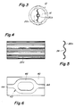
- Fig. 4. is an elevational view of the foil member portion of the inlead assembly of the present invention.
- Fig. 5 is a side elevational view of the foil member of fig. 4.
- Fig. 6 is an elevational view of a foil member constructed in accordance with an alternate embodiment of the present invention.
- a light source 10 is illustrated having a lamp envelope 12 with a central portion having a chamber 14 formed therein and two opposite ended tubular end portions 16.
- the light source 10 of fig. 1 is an incandescent light source having a filament member 18 disposed along the central, or longitudinal axis of the lamp envelope 12. Connected to opposite ends of filament 18 are respective first and second lamp inlead assemblies 20, 22.
- Lamp inlead assemblies 20, 22 include respective inner lead wire members 20a, 22a which are connected to the ends of the filament 18, outer lead wire members 20b, 22b which extend outward from the end region of the lamp envelope 12 so that power can be connected to the light source 10, and, thin foil members 20c, 22c which are constructed of molybdenum and are typically on the order of approximately 1 mil (2.54 ⁇ 10 -3 cm) in thickness but in some extreme cases, can be as high as 3 mils (7.62 ⁇ 10 -3 cm).
- the lamp inlead assemblies 20, 22 are disposed in the end regions 12a, 12b of the lamp envelope 12 and, during one of the last steps in the lamp manufacturing process, are hermetically sealed in these end regions 12a, 12b either by a heat shrinking or a pressing/pinching process as are common in the field.
- the light source 10 is shown as a double ended light source, it is possible to utilize the improved lamp inlead assemblies 20, 22 of the present invention in a single ended light source where such single end is wider to accommodate insertion of two lamp inlead assemblies in a side by side physical relationship.
- a coating is placed on the surface of the lamp envelope 12 so as to cause infrared radiation (IR) given off by the filament 18 to be reflected back to the filament 18 thereby improving the energy efficiency of this type of light source 10.
- IR infrared radiation
- This type of light source has been available from General Electric Company's Lighting Business as their Halogen-IR (TM) light source.
- TM Halogen-IR
- Halogen-IR lamp in attaining its improved energy efficiency is in the central placement of the filament 18 along the longitudinal axis of the lamp envelope 12 which allows for absorbing as much of the reflected IR back into the filament 18 as possible.
- the light source 30 shown in fig. 2 is identical to that shown in fig. 1 except that, instead of a filament 18 serving as the light generating element, light source 30 is a discharge light source which utilizes spaced apart electrodes 32, 34 as a means for generating light output.
- the two electrodes 32, 34 are different in size with the anode member 34 being larger than the cathode member 32 as is the typical case in running such a discharge lamp 30 using a DC energy source. It is to be understood that the present invention would apply equally as well with a discharge lamp that is powered from an AC source.
- Another difference between the light source 30 of fig. 2 and that of fig. 1 is in the lengths of the respective inner lead wire members 20a, 22a. It can be seen that since the electrodes 32, 34 are of a different length, it is necessary to alter the lengths of the inner lead wire members 20a, 20b so that the resulting arc discharge will reside essentially at the center region of the chamber 14 of the lamp envelope 12.
- the filament 18 of the light source 10 shown in fig. 1 reside substantially along the longitudinal axis of the lamp envelope 12
- a similar requirement is also necessary with respect to applying the lamp inlead assemblies 20, 22 of the present invention to the discharge light source 30 as shown in fig. 3.
- the arc discharge (not shown) of the discharge light source 30 has high thermal operating characteristics associated therewith, it is necessary to maintain the electrodes 32, 34 at a substantially central position within the chamber 14 so that the arc discharge does not contact the walls of the lamp envelope 12.
- a cross-sectional view taken along line a-a from either fig. 1 or fig. 2 illustrates one of the end regions 16 of the lamp envelope 12 including the configuration between the foil members 20c, 22c and the inner and outer lead wire members 20a, 22a, 20b, 22b that allows for the precise control of the positioning between components as was discussed hereinabove.
- the end region 16 of the lamp envelope 12 is sealed around the lamp inlead assembly 20 or 22 in a manner so as to hermetically seal the chamber 14 formed in the lamp envelope 12.
- the sealing process can be of any conventional type for light sources, such as by means of a heat shrinking process or a pinch/press process.
- the integrity of the seal at the end region 16 of the lamp envelope 12 depends largely on the thickness of the foil member 20c, 22c.
- the foil member 20c, 22c has a thickness on the order of approximately 1 mill with the edges being feathered even thinner to allow for a more secure seal.
- the thin foil member 20c, 22c is susceptible to damage particularly when used with high speed automated manufacturing equipment (not shown) which includes devices for handling the thin foil member 20c, 22c that are not delicate in nature.
- the thin foil member 20c, 22c of the present invention achieves a greater strength and rigidity than would otherwise be attainable for such a thin material without the need to increase the thickness at any point and incur a design tradeoff penalty in the form of a less secure seal.
- the thin foil members 20c, 22c maintain essentially the same uniform thickness and foil surface width as a conventional thin foil but is strengthened by way of the troughs 36 that are formed lengthwise on the foil members 20c, 22c (extending into the drawing when viewed from fig. 3).
- the foil member 20c, 22c construction of the present invention as claimed still allows for a cross-wise dimension or width whereby a clearance exists between the feathered edges of the foil member 20c, 22c and the inner wall surfaces of the lamp envelope 12.
- the present invention as claimed provides a more easily adapted high speed automated assembly capability since there is no risk of the foil member catching or otherwise binding up during the manufacturing stage of pulling the inlead assembly into the lamp envelope.
- the manufacturing process can be conducted at a faster rate than could be achieved using an inlead assembly that was in contact with the lamp envelope.
- this clearance feature allows for less expensive automated equipment since the tolerances on the tooling used to align and insert the inlead assembly into the lamp envelope can be relaxed.
- a centrally located trough 36 Disposed in a centrally located trough 36 is a portion of one of the inner or outer lead wire members 20a, 22a, 20b, 22b.
- the curved dimension of this central trough 36 is selected so as to closely coincide with the diameter of the lead wires so that the inner and outer lead wires 20a, 22a, 20b, 22b can rest within the trough 36 in an essentially nested manner. In this manner, it can be appreciated that securing the lead wire to the thin foil 20c, 22c for purposes of controlling the positioning of such components relative to one another, can be accurately achieved.
- the lead wire member Once the lead wire member has been positioned within the trough 36 of the foil member 20c, 22c, the lead wire member can be secured thereto using known techniques such as welding or brazing.
- the curvilinear dimensions of the various troughs can differ thereby providing a recognizable distinction between the troughs 36 that may be utilized in high speed automated equipment to verify that the lead wire member does in fact sit within the proper trough 36.
- the foil member 20c, 22c shown in fig. 3 includes three troughs 36, it is possible to practice the principles of the present invention by the use of an alternate number of troughs, such alternate arrangement being contemplated as within the scope of the present invention.
- Figs. 4 and 5 illustrate further views of the foil member 20a, 22c alone and indicate that the troughs 36 can be pressed into the foil member 20c, 22c along the entire length of the foil member.
- a greater surface area is achieved so that adequate current carrying capabilities are achieved without adding to the dimensional requirements needed to accommodate other larger foil members as shown in the prior art.
- the tolerance in the length of the lead wire members can be relaxed thereby allowing the lead wires to extend further onto the foil member without experiencing drifting away from the central position.
- the process for constructing the foil members 20c, 22c can be automated thereby making the cost of such a device very similar to that of a flat foil configuration.
- foil member 40 portion of the lamp inlead assembly 20, 22 can provide for a trough arrangement 42 which does not extend in a straight manner for the length of this foil member 40.
- foil member 40 includes a trough arrangement 42 having end straight portions 44 and an inner oval portion 46 connected thereto to form one continuous path along the length of the foil member 40.
- the foil member 40 shown in fig. 6 allows for the same control over the positioning of the lead wire members relative to the foil member 40.
- the oval configuration of the inner trough portion 46 of foil member 40 it can be appreciated that the strength of this foil member 40 has been increased when measured from a side to side dimension as well as having been maintained when measured from an end to end dimension.
- the trough configuration for the foil members shown in figs. 4 through 6 insure that there is control over the flat, two-dimensional nature of this assembly. In other words, the trough configurations are effective for preventing the lamp inlead assembly 20 or 22 from sagging during lamp assembly.
Landscapes
- Vessels And Coating Films For Discharge Lamps (AREA)
Description
- This invention relates to a lamp inlead assembly having an improved formed molybdenum foil configuration. More particularly, this invention relates to such a lamp inlead assembly as exhibits improved stability characteristics that allow for implementation in a high speed automated manufacturing environment so as to achieve accurate positioning of the inlead assembly within the lamp without risking damage to the inlead assembly as may otherwise be caused by the manufacturing process.
- A conventional lamp inlead assembly which can be utilized for instance in a high pressure discharge lamp or a halogen filament lamp, typically includes an outer lead wire, a thin molybdenum foil and an inner lead wire. This assembly can be inserted into a double ended lamp envelope which is then pressed, or shrunk over the inlead assembly to provide a hermetic seal for the inner chamber of the lamp envelope. Typically, the molybdenum foil is extremely thin, being on the order of no more than 3 mils (7.62 × 10⁻³ cm) thick with feathered edges on either side. Though the feathered edges are effective for allowing a more complete sealing operation to be performed at the ends of the lamp envelope, such feathered edges are susceptible to damage when handled during the lamp assembly process particularly if a high speed automated manufacturing process is utilized for assembly of the lamp or the lamp inlead assembly.
- One approach to avoid the handling problem for thin molybdenum foils can be found in US Patent No. 4,254,356 issued to Karikas on March 3, 1991 and assigned to the same assignee as the present invention. In this patent, a Z-shaped foil configuration is utilized wherein the edges of the foil are turned outward in opposite directions thereby rendering the foil member more rigid and less susceptible to damage from indelicate handling. This approach has proven effective not only in strengthening the foil member but has done so without suffering from a reduction in the quality of the seal formed by shrinking or pressing the end of the lamp envelope around the lamp inlead assembly.
- One problem that has remained however in the use of such a Z-shaped foil configuration relates to the ability to maintain the control of the positioning between the lead wires and the foil member just prior to and/or just after attachment of the lead wires to the foil member. That is, because the center portion of the Z-shaped foil member is essentially flat, maintaining the essentially round lead wire in a precise position for first welding or brazing to the foil member and then placing the entire assembly essentially centrally within the lamp envelope end prior to sealing, has proven to be difficult. For optimum lamp performance, it is essential that the inner lead wire reside on center of the lamp envelope. A lead wire that is either off center relative to the foil member or is at an angle relative to the edges of the foil member, can result in a poor seal around the lamp inlead assembly or can put stress on the connection between the lead wire and foil member such that early failure of the lamp would occur. Additionally, such a positioning error would result in electrode misalignment in a discharge lamp or an off-center filament for a Halogen-IR lamp, both of which conditions are to be avoided. Another problem associated with the Z-shaped configuration is in the manufacturing operation associated with inserting this lamp inlead assembly into a lamp envelope. For the Z-shaped arrangement, the practice has been to have the top and bottom portions of the foil member contact the inner surface of the end region of the lamp envelope. Such a contacting operation inherently slows down the manufacturing process and is less efficient than one where there was a clearance provided between the foil member and the surface of the lamp envelope.
- Other approaches to solving the problem of the delicate handling requirement of the foil member so that a precise and secure seal can be formed there around, can be found in US Patent Nos. 3,582,704; 4,136,298; and, 4,851,733. In each of these patents, a foil member is utilized which has a non-uniform thickness associated therewith. In other words, the foil members have various shapes, thicknesses and various gradations in thickness to provide stability, strength and sufficient foil member dimension to insure adequate current carrying capabilities. The problem with such a variation in the thickness and shape of the foil however is that the sealing process for sealing the end of the lamp envelope around the inlead assembly containing the thicker foil member is adversely affected by the increased thickness of the foil member and the quality of such seal may suffer accordingly.
- It would therefore be advantageous if an inlead assembly could be provided that would include a foil member that was thin enough to insure a proper, high quality seal at the end of the lamp envelope, could achieve such high quality seal even when utilized in a high speed automated manufacturing environment and further, could allow that the positioning between the lead wires and the foil be accurately maintained throughout the lamp manufacturing process. It would be further advantageous if such a lamp inlead assembly could accomplish all of these features while at the same time, insuring that a sufficient foil dimension control is achieved to handle the necessary current while providing additional space for clearance of the foil member during lamp manufacture.
- GB-A-2048563 discloses an inlead assembly for a discharge lamp. The inlead has a foil portion which is stiffened by folding the lateral edges in opposite directions. The folds overlap a tapering region of greater stiffness where the foil portion joins the end portions. In making a discharge lamp, the electrode-inlead assembly is self-centering as a result of making the overall width of the foil portion and its folded edges exceed slightly the internal diameter of the quartz tube or neck. The frictional engagement between the folded edges and the inside wall of the neck retains the assembly in place while the neck is heat-collapsed onto the foil to seal the electrode assembly in place.
- US-A-4851733 discloses an electric lamp having elongated metal foils as a part of the current conductor lead-throughs. Each metal foil has a major surfaces which meet one another along each opposing side edge of the foil at an acute angle. The metal foil has a cross-section transverse to the side edges. At least one of the major surfaces has a pair of concave curvature portions each adjoining a respective side edge, and a convex curvature portion extending between the pair of concave curvature portions.
- Soviet Patent Abstracts, Section EI,
Week 9344, 22 December 1993, Derwent Publications Ltd., London, Class X26, AN 93-350121 and SU-A-1772840 disclose an electrode unit for a gaseous discharge lamp. - The electrode unit has a cylindrical quartz insert welded into the quartz stem of the lamp. The insert is squeezed along a lateral surface by an open cylinder made from foil, connected by one end to a current lead-in and by a second end to an electrode. A protection strip is positioned in the connection region of the cylinder with the electrode.
- The lamp reliability and its service life are increased due to its operation in a horizontal position, by making the protection strip with corrugated zigzag shaped surface, and the height to width ratio of corrugation selected between 0.05 to 0.2 of electrode dia.
- According to the invention there is provided a lamp inlead assembly having the features recited in claim 1.
- Further according to the invention there is provided a light source having the features of claim 7.
- The present invention may be used for a light source having a light generating means whether filament or discharge oriented, disposed in a lamp envelope which can be either single ended or double ended and wherein an improved lamp inlead assembly is provided for coupling energy to the light generating means. This improved lamp inlead assembly allows for the use of an effective sealing process that can be implemented on high speed automated manufacturing equipment without risk of damage to the thin foil portion of the inlead assembly. The improved inlead assembly of the present invention also allows for the precise positioning between the lead wire portions and the foil member during the manufacturing steps of securing the lead wires to the foil and of inserting and sealing the lamp inlead assembly in the end region of the lamp envelope. Moreover, the improved lamp inlead assembly achieves this and allows for sufficient current carrying capabilities while providing additional space for clearance of the foil member during lamp manufacture.
- Preferably, the at least one trough section is formed centrally along the longitudinal axis of the foil member and is sized so that portions of either or both of the inner and outer lead wire members can be disposed therein in an essentially fitted manner. This fitted relation between the lead wires and the foil member is effective so as to prevent shifting of the lead wire members relative to the foil member during assembly of the inlead assembly or insertion and sealing of the inlead assembly into the end region of the lamp. The use of a trough configuration is further effective in increasing the relative surface area of the foil member so as to insure adequate current carrying capabilities without increasing the necessary space requirements for such foil member and furthermore, simultaneously achieves a more rigid construction for such inlead assembly.
- In the following detailed description, reference will be made to the attached drawings in which:
- Fig. 1 is an elevational view in section of a first light source type having the improved inlead assembly of the present invention disposed therein.
- Fig. 2 is an elevational view in section of a second light source type having the improved inlead assembly of the present invention disposed therein.
- Fig. 3 is a side sectional view of the light source of either fig. 1 or fig. 2 taken along sections a-a showing the inlead assembly constructed in accordance with the present invention.
- Fig. 4. is an elevational view of the foil member portion of the inlead assembly of the present invention.
- Fig. 5 is a side elevational view of the foil member of fig. 4.
- Fig. 6 is an elevational view of a foil member constructed in accordance with an alternate embodiment of the present invention.
- As seen in fig. 1, a
light source 10 is illustrated having alamp envelope 12 with a central portion having achamber 14 formed therein and two opposite endedtubular end portions 16. Thelight source 10 of fig. 1 is an incandescent light source having afilament member 18 disposed along the central, or longitudinal axis of thelamp envelope 12. Connected to opposite ends offilament 18 are respective first and second lamp inleadassemblies assemblies lead wire members filament 18, outerlead wire members lamp envelope 12 so that power can be connected to thelight source 10, and,thin foil members - The lamp inlead
assemblies lamp envelope 12 and, during one of the last steps in the lamp manufacturing process, are hermetically sealed in these end regions 12a, 12b either by a heat shrinking or a pressing/pinching process as are common in the field. Although thelight source 10 is shown as a double ended light source, it is possible to utilize the improved lamp inleadassemblies - In a typical commercial application of the filament based
light source 10 as shown in fig. 1, a coating is placed on the surface of thelamp envelope 12 so as to cause infrared radiation (IR) given off by thefilament 18 to be reflected back to thefilament 18 thereby improving the energy efficiency of this type oflight source 10. This type of light source has been available from General Electric Company's Lighting Business as their Halogen-IR (TM) light source. For a discussion of the operation of such a lamp, reference is hereby made to US Patent No. 4,810,932 issued to Ahlgren et al on March 7, 1989 and assigned to the same assignee as the present invention. One of the key features of the Halogen-IR lamp in attaining its improved energy efficiency is in the central placement of thefilament 18 along the longitudinal axis of thelamp envelope 12 which allows for absorbing as much of the reflected IR back into thefilament 18 as possible. To attain this centralized placement of thefilament 18 within thelamp envelope 12, it is necessary to maintain accurate control over the positioning of the inner and outerlead wire members thin foil members lamp inlead assemblies lamp inlead assemblies filament 18,inlead assembly lamp envelope 12 for sealing therein. Such position accuracy during the sealing process is necessary to insure that the filament resides as closely as possible to the central longitudinal axis of thelamp envelope 12. These positioning control considerations will be discussed in further detail with respect to figs. 3 through 6. - The
light source 30 shown in fig. 2 is identical to that shown in fig. 1 except that, instead of afilament 18 serving as the light generating element,light source 30 is a discharge light source which utilizes spaced apartelectrodes electrodes anode member 34 being larger than thecathode member 32 as is the typical case in running such adischarge lamp 30 using a DC energy source. It is to be understood that the present invention would apply equally as well with a discharge lamp that is powered from an AC source. Another difference between thelight source 30 of fig. 2 and that of fig. 1 is in the lengths of the respective innerlead wire members electrodes lead wire members chamber 14 of thelamp envelope 12. - As in the requirement that the
filament 18 of thelight source 10 shown in fig. 1 reside substantially along the longitudinal axis of thelamp envelope 12, a similar requirement is also necessary with respect to applying thelamp inlead assemblies discharge light source 30 as shown in fig. 3. Because the arc discharge (not shown) of thedischarge light source 30 has high thermal operating characteristics associated therewith, it is necessary to maintain theelectrodes chamber 14 so that the arc discharge does not contact the walls of thelamp envelope 12. Accordingly, the previous discussion regarding the control over the positioning of the inner andouter lead wires foil members lamp inlead assemblies lamp envelope 12 is pertinent here as well. - As seen in fig. 3, a cross-sectional view taken along line a-a from either fig. 1 or fig. 2, illustrates one of the
end regions 16 of thelamp envelope 12 including the configuration between thefoil members lead wire members end region 16 of thelamp envelope 12 is sealed around thelamp inlead assembly chamber 14 formed in thelamp envelope 12. The sealing process can be of any conventional type for light sources, such as by means of a heat shrinking process or a pinch/press process. - It is known that the integrity of the seal at the
end region 16 of thelamp envelope 12 depends largely on the thickness of thefoil member foil member thin foil member thin foil member thin foil member thin foil members troughs 36 that are formed lengthwise on thefoil members foil member foil member lamp envelope 12. By this clearance arrangement, the present invention as claimed provides a more easily adapted high speed automated assembly capability since there is no risk of the foil member catching or otherwise binding up during the manufacturing stage of pulling the inlead assembly into the lamp envelope. As such, the manufacturing process can be conducted at a faster rate than could be achieved using an inlead assembly that was in contact with the lamp envelope. Moreover, it can be appreciated that this clearance feature allows for less expensive automated equipment since the tolerances on the tooling used to align and insert the inlead assembly into the lamp envelope can be relaxed. - Disposed in a centrally located
trough 36 is a portion of one of the inner or outerlead wire members
The curved dimension of thiscentral trough 36 is selected so as to closely coincide with the diameter of the lead wires so that the inner andouter lead wires trough 36 in an essentially nested manner. In this manner, it can be appreciated that securing the lead wire to thethin foil trough 36 of thefoil member - As further seen in fig. 3, the curvilinear dimensions of the various troughs (central and outer) can differ thereby providing a recognizable distinction between the
troughs 36 that may be utilized in high speed automated equipment to verify that the lead wire member does in fact sit within theproper trough 36. Additionally, it can be appreciated that although thefoil member troughs 36, it is possible to practice the principles of the present invention by the use of an alternate number of troughs, such alternate arrangement being contemplated as within the scope of the present invention. - Figs. 4 and 5 illustrate further views of the
foil member troughs 36 can be pressed into thefoil member troughs 36 extending the length of thefoil members foil members - As seen in fig. 6, an alternate embodiment for the
foil member 40 portion of thelamp inlead assembly trough arrangement 42 which does not extend in a straight manner for the length of thisfoil member 40. Instead,foil member 40 includes atrough arrangement 42 having endstraight portions 44 and an inneroval portion 46 connected thereto to form one continuous path along the length of thefoil member 40. Similar to the foil member configuration illustrated in figs. 4 and 5, thefoil member 40 shown in fig. 6 allows for the same control over the positioning of the lead wire members relative to thefoil member 40. Additionally, because of the oval configuration of theinner trough portion 46 offoil member 40, it can be appreciated that the strength of thisfoil member 40 has been increased when measured from a side to side dimension as well as having been maintained when measured from an end to end dimension. - With this trough arrangement as shown in both foil member configurations, the dimensional control of the entire
lamp inlead assembly lamp envelope 12 for one of the final steps in the lamp assembly/manufacture, is accurately maintained. The trough configuration for the foil members shown in figs. 4 through 6 insure that there is control over the flat, two-dimensional nature of this assembly. In other words, the trough configurations are effective for preventing thelamp inlead assembly - Although the hereinabove described embodiment of the invention constitutes the preferred embodiment, it should be understood that modifications can be made thereto without departing from the scope of the invention as set forth in the appended claims. For instance, instead of the oval shaped
inner trough portion 46 shown in fig. 6, it would be possible to utilize an S-shaped inner trough portion, or some other shape that resulted in increased rigidity of the foil member, and still practice the principles of the present invention as claimed. Additionally, although the trough sections of the present invention as claimed are shown having an arcuate or rounded shape with an essentially uniform radius and pitch characteristics as well as having a symmetrical waveshape associated therewith, it is not intended that this invention as claimed be limited to such a configuration. It is possible to modify the pitch and radii of the trough sections and/or to utilize a non-symmetrical waveshape and still practice the present invention as claimed.
Claims (9)
- A lamp inlead assembly (20, 22) for a light source (10, 30) having a lamp envelope (12) with at least one end region (16) in which said lamp inlead assembly (20, 22) is sealably disposed, said lamp inlead assembly (20, 22) comprising:an outer lead wire member (20b, 22b) which partially extends outward of the end region (16) of said lamp envelope (12) so as to allow coupling of energy to said light source (10, 30);an inner lead wire member (20a, 22a) which partially extends inward to a chamber (14) formed in said lamp envelope (12); anda foil member (20c) disposed between said outer lead wire member (20b, 22b) and said inner lead wire member (20a, 22a), said inner and outer lead wire members being fixedly secured to said foil member (20c);said foil member (20c) being constructed of foil having an essentially uniform thickness; characterized in that:said foil member (20c) has at least one trough section (36) formed therein, said at least one trough section (36) extending at least partially along the lengthwise dimension of said foil member (20c) and having portions in which at least one of said inner and said outer lead wire members (20a, 22a, 20b, 22b) is disposed in a fitted manner.
- The lamp inlead assembly as set forth in claim 1, wherein edges of said foil member (20c) are feathered so as to insure an adequate seal of said at least one end region (16) around said lamp inlead assembly (20, 22).
- The lamp inlead assembly as set forth in claim 1 or 2, wherein said at least one trough section (36) is a plurality of trough sections extending in a straight line for the length of said foil member (20c).
- The lamp inlead assembly as set forth in claim 3, wherein said plurality of trough sections (36) includes a center trough section formed at the midpoint along thewidth of said foil member (20c), and a plurality of outer trough sections formed symmetrically about said center trough section, said inner and outer lead wire members (20a, 20b, 22a, 22b) being disposed in said center trough section (36).
- The lamp inlead assembly as set forth in claim 3, wherein said at least one trough section includes outer, straight trough sections (44) and an inner, curved trough section (46); said outer straight trough sections (44) being formed at approximately the midpoint along the width of said foil member (40) and having said inner and outer lead wire members (20a, 20b, 22a, 22b) disposed therein.
- The lamp inlead assembly as set forth in claim 5, wherein said center curved trough section (46) is oval shaped and said outer straight trough sections (44) connect into said oval-shaped inner trough section (46) in a continuous manner.
- A light source (10, 30) comprising:a lamp envelope (12) made of a light transmissive material, having a chamber (14) formed therein and further having at least one end region (16) associated therewith;light generating means (18, 32, 34) disposed within said chamber (14) and effective upon energization thereof, for generating light output; anda pair of lamp inlead assemblies (20, 22) according to any one of claims 1 to 6, extending through said at least one end region (16) of said lamp envelope (12) and effective so that energy can be coupled to said light generating means (18, 32, 34).
- The light source as set forth in claim 7, wherein said light generating means includes a filament member (18) on which said respective inner lead wire members (20a, 22a) of said pair of lamp inlead assemblies (20, 22) are connected at opposite ends thereof.
- The light source as set forth in claim 7, wherein said light generating means includes a pair of electrodes (32, 34) across which an arc discharge is generated upon excitation of said light source, said respective inner lead wire members (20a, 22) of said pair of lamp inlead assemblies (20, 22) being connected respectively to a corresponding one of said electrode members (32, 34).
Applications Claiming Priority (2)
| Application Number | Priority Date | Filing Date | Title |
|---|---|---|---|
| US08/096,531 US5430353A (en) | 1993-07-22 | 1993-07-22 | Lamp inlead assembly having a formed foil arrangement |
| US96531 | 1993-07-22 |
Publications (2)
| Publication Number | Publication Date |
|---|---|
| EP0635866A1 EP0635866A1 (en) | 1995-01-25 |
| EP0635866B1 true EP0635866B1 (en) | 1997-09-03 |
Family
ID=22257793
Family Applications (1)
| Application Number | Title | Priority Date | Filing Date |
|---|---|---|---|
| EP94304500A Expired - Lifetime EP0635866B1 (en) | 1993-07-22 | 1994-06-21 | Lamp inlead assembly having a formed foil arrangement |
Country Status (4)
| Country | Link |
|---|---|
| US (1) | US5430353A (en) |
| EP (1) | EP0635866B1 (en) |
| JP (1) | JPH07153436A (en) |
| DE (1) | DE69405333T2 (en) |
Families Citing this family (12)
| Publication number | Priority date | Publication date | Assignee | Title |
|---|---|---|---|---|
| DE19727430A1 (en) * | 1997-06-27 | 1999-01-07 | Patent Treuhand Ges Fuer Elektrische Gluehlampen Mbh | Metal halide lamp with ceramic discharge tube |
| DE19912544B4 (en) * | 1999-03-19 | 2007-01-18 | Heraeus Noblelight Gmbh | Infrared radiator and method for heating a material to be treated |
| JP3085303B1 (en) * | 1999-07-05 | 2000-09-04 | ウシオ電機株式会社 | Discharge lamp |
| US6897612B2 (en) * | 2000-04-03 | 2005-05-24 | Matsushita Electric Industrial Co., Ltd. | Discharge lamp, method for producing the same and lamp unit |
| JP2003178714A (en) * | 2001-12-12 | 2003-06-27 | Ushio Inc | Short arc type ultra-high pressure discharge lamp |
| US6661172B2 (en) * | 2002-01-11 | 2003-12-09 | General Electric Company | Electrode assembly and lamp with conductor foil |
| JP3570414B2 (en) * | 2002-03-05 | 2004-09-29 | ウシオ電機株式会社 | Short arc type ultra-high pressure discharge lamp |
| US6856091B2 (en) * | 2002-06-24 | 2005-02-15 | Matsushita Electric Industrial Co., Ltd. | Seal for ceramic metal halide discharge lamp chamber |
| JP2004265753A (en) * | 2003-03-03 | 2004-09-24 | Ushio Inc | Short arc type ultra-high pressure discharge lamp |
| DE202004014711U1 (en) * | 2004-09-21 | 2005-11-10 | Patent-Treuhand-Gesellschaft für elektrische Glühlampen mbH | Electric lamp closed by foil sealing |
| JP4972172B2 (en) * | 2007-12-12 | 2012-07-11 | ハリソン東芝ライティング株式会社 | Discharge lamp |
| CN103021792A (en) * | 2012-12-31 | 2013-04-03 | 悍飞照明科技股份有限公司 | Ultrahigh-pressure projection lamp |
Family Cites Families (7)
| Publication number | Priority date | Publication date | Assignee | Title |
|---|---|---|---|---|
| NL106429C (en) * | 1959-09-23 | 1963-11-15 | Philips Nv | Method for manufacturing an electric lamp, as well as an electric lamp manufactured according to this method |
| JPS4911820B1 (en) * | 1968-11-06 | 1974-03-19 | ||
| US3548245A (en) * | 1969-02-13 | 1970-12-15 | Gen Electric | Quartz-to-metal foil pinch seal |
| US4110657A (en) * | 1977-03-14 | 1978-08-29 | General Electric Company | Lead-in seal and lamp utilizing same |
| US4254356A (en) * | 1979-04-23 | 1981-03-03 | General Electric Company | Inlead and method of making a discharge lamp |
| CN1005176B (en) * | 1985-04-09 | 1989-09-13 | 菲利普白炽灯有限公司 | light bulb |
| RU1772840C (en) * | 1991-01-24 | 1992-10-30 | Всесоюзный научно-исследовательский, проектно-конструкторский и технологический институт источников света им.А.Н.Лодыгина | Electrode unit of gaseous discharge lamp |
-
1993
- 1993-07-22 US US08/096,531 patent/US5430353A/en not_active Expired - Lifetime
-
1994
- 1994-06-21 DE DE69405333T patent/DE69405333T2/en not_active Expired - Fee Related
- 1994-06-21 EP EP94304500A patent/EP0635866B1/en not_active Expired - Lifetime
- 1994-07-21 JP JP6168506A patent/JPH07153436A/en active Pending
Also Published As
| Publication number | Publication date |
|---|---|
| JPH07153436A (en) | 1995-06-16 |
| DE69405333D1 (en) | 1997-10-09 |
| US5430353A (en) | 1995-07-04 |
| DE69405333T2 (en) | 1998-03-26 |
| EP0635866A1 (en) | 1995-01-25 |
Similar Documents
| Publication | Publication Date | Title |
|---|---|---|
| US5430353A (en) | Lamp inlead assembly having a formed foil arrangement | |
| CA1225115A (en) | Quartz infra-red lamps | |
| US5742114A (en) | Lamp envelope with a metal clamping member and a fixation member | |
| EP0895275A3 (en) | Tungsten halogen lamp and method for manufacturing the same | |
| JPS6276149A (en) | Fluorescent lamp | |
| JP3704204B2 (en) | Halogen bulb | |
| EP0818805A3 (en) | Discharge lamp ARC tube and method of producing the same | |
| US6369509B1 (en) | Short arc lamp with crack-preventing electric mounting arrangement | |
| JP2586587Y2 (en) | Compact low-pressure discharge lamp | |
| US4808877A (en) | Low-pressure sodium discharge lamp having a collar-like heat shield | |
| US20040100196A1 (en) | Discharge lamp of the short arc type | |
| EP0156384A2 (en) | Electrode alignment and capsule design for single-ended low wattage metal halide lamps | |
| JPH0364817A (en) | High voltage vacuum insulation vessel | |
| US4658177A (en) | Electric lamp with oriented current conductors extending through a press seal | |
| US5440196A (en) | Dual-envelope high-pressure discharge lamp construction, and method of its manufacture | |
| JPS61237363A (en) | Lamp | |
| US6680572B1 (en) | Incandescent lamp comprising a glass bulb of tubular shape in which a filament is axially arranged | |
| GB2107513A (en) | Electrodes for discharge lamps | |
| EP1465239A3 (en) | Metal vapour discharge lamp | |
| EP0156383A2 (en) | Electrode alignment and capsule design for single-ended low wattage metal halide lamps | |
| EP1865527B1 (en) | Discharge lamp and metal foil for a discharge lamp | |
| JPH05325899A (en) | Tubular bulb | |
| US4868452A (en) | Electric amp having a flexible conductor connecting a plurality of external pinch seal conductors to a rigid current-supply conductor | |
| EP0441387A2 (en) | Low pressure gas discharge lamp | |
| JPS63254662A (en) | Lamp |
Legal Events
| Date | Code | Title | Description |
|---|---|---|---|
| PUAI | Public reference made under article 153(3) epc to a published international application that has entered the european phase |
Free format text: ORIGINAL CODE: 0009012 |
|
| AK | Designated contracting states |
Kind code of ref document: A1 Designated state(s): DE FR GB IT |
|
| 17P | Request for examination filed |
Effective date: 19950725 |
|
| 17Q | First examination report despatched |
Effective date: 19960206 |
|
| GRAG | Despatch of communication of intention to grant |
Free format text: ORIGINAL CODE: EPIDOS AGRA |
|
| GRAH | Despatch of communication of intention to grant a patent |
Free format text: ORIGINAL CODE: EPIDOS IGRA |
|
| GRAH | Despatch of communication of intention to grant a patent |
Free format text: ORIGINAL CODE: EPIDOS IGRA |
|
| GRAA | (expected) grant |
Free format text: ORIGINAL CODE: 0009210 |
|
| AK | Designated contracting states |
Kind code of ref document: B1 Designated state(s): DE FR GB IT |
|
| ET | Fr: translation filed | ||
| REF | Corresponds to: |
Ref document number: 69405333 Country of ref document: DE Date of ref document: 19971009 |
|
| ITF | It: translation for a ep patent filed | ||
| PLBE | No opposition filed within time limit |
Free format text: ORIGINAL CODE: 0009261 |
|
| STAA | Information on the status of an ep patent application or granted ep patent |
Free format text: STATUS: NO OPPOSITION FILED WITHIN TIME LIMIT |
|
| 26N | No opposition filed | ||
| PGFP | Annual fee paid to national office [announced via postgrant information from national office to epo] |
Ref country code: FR Payment date: 20010531 Year of fee payment: 8 |
|
| REG | Reference to a national code |
Ref country code: GB Ref legal event code: IF02 |
|
| PGFP | Annual fee paid to national office [announced via postgrant information from national office to epo] |
Ref country code: DE Payment date: 20020620 Year of fee payment: 9 |
|
| PG25 | Lapsed in a contracting state [announced via postgrant information from national office to epo] |
Ref country code: FR Free format text: LAPSE BECAUSE OF NON-PAYMENT OF DUE FEES Effective date: 20030228 |
|
| REG | Reference to a national code |
Ref country code: FR Ref legal event code: ST |
|
| PG25 | Lapsed in a contracting state [announced via postgrant information from national office to epo] |
Ref country code: DE Free format text: LAPSE BECAUSE OF NON-PAYMENT OF DUE FEES Effective date: 20040101 |
|
| PG25 | Lapsed in a contracting state [announced via postgrant information from national office to epo] |
Ref country code: IT Free format text: LAPSE BECAUSE OF NON-PAYMENT OF DUE FEES;WARNING: LAPSES OF ITALIAN PATENTS WITH EFFECTIVE DATE BEFORE 2007 MAY HAVE OCCURRED AT ANY TIME BEFORE 2007. THE CORRECT EFFECTIVE DATE MAY BE DIFFERENT FROM THE ONE RECORDED. Effective date: 20050621 |
|
| PGFP | Annual fee paid to national office [announced via postgrant information from national office to epo] |
Ref country code: GB Payment date: 20080627 Year of fee payment: 15 |
|
| GBPC | Gb: european patent ceased through non-payment of renewal fee |
Effective date: 20090621 |
|
| PG25 | Lapsed in a contracting state [announced via postgrant information from national office to epo] |
Ref country code: GB Free format text: LAPSE BECAUSE OF NON-PAYMENT OF DUE FEES Effective date: 20090621 |