EP0634278B1 - Tape cutting apparatus - Google Patents
Tape cutting apparatus Download PDFInfo
- Publication number
- EP0634278B1 EP0634278B1 EP94304286A EP94304286A EP0634278B1 EP 0634278 B1 EP0634278 B1 EP 0634278B1 EP 94304286 A EP94304286 A EP 94304286A EP 94304286 A EP94304286 A EP 94304286A EP 0634278 B1 EP0634278 B1 EP 0634278B1
- Authority
- EP
- European Patent Office
- Prior art keywords
- blade
- cassette
- cutting
- tape
- protection member
- Prior art date
- Legal status (The legal status is an assumption and is not a legal conclusion. Google has not performed a legal analysis and makes no representation as to the accuracy of the status listed.)
- Expired - Lifetime
Links
Images


Classifications
-
- B—PERFORMING OPERATIONS; TRANSPORTING
- B26—HAND CUTTING TOOLS; CUTTING; SEVERING
- B26D—CUTTING; DETAILS COMMON TO MACHINES FOR PERFORATING, PUNCHING, CUTTING-OUT, STAMPING-OUT OR SEVERING
- B26D7/00—Details of apparatus for cutting, cutting-out, stamping-out, punching, perforating, or severing by means other than cutting
- B26D7/22—Safety devices specially adapted for cutting machines
- B26D7/24—Safety devices specially adapted for cutting machines arranged to disable the operating means for the cutting member
-
- B—PERFORMING OPERATIONS; TRANSPORTING
- B41—PRINTING; LINING MACHINES; TYPEWRITERS; STAMPS
- B41J—TYPEWRITERS; SELECTIVE PRINTING MECHANISMS, i.e. MECHANISMS PRINTING OTHERWISE THAN FROM A FORME; CORRECTION OF TYPOGRAPHICAL ERRORS
- B41J11/00—Devices or arrangements of selective printing mechanisms, e.g. ink-jet printers or thermal printers, for supporting or handling copy material in sheet or web form
- B41J11/66—Applications of cutting devices
- B41J11/70—Applications of cutting devices cutting perpendicular to the direction of paper feed
- B41J11/703—Cutting of tape
-
- B—PERFORMING OPERATIONS; TRANSPORTING
- B65—CONVEYING; PACKING; STORING; HANDLING THIN OR FILAMENTARY MATERIAL
- B65H—HANDLING THIN OR FILAMENTARY MATERIAL, e.g. SHEETS, WEBS, CABLES
- B65H35/00—Delivering articles from cutting or line-perforating machines; Article or web delivery apparatus incorporating cutting or line-perforating devices, e.g. adhesive tape dispensers
- B65H35/0006—Article or web delivery apparatus incorporating cutting or line-perforating devices
- B65H35/0073—Details
- B65H35/008—Arrangements or adaptations of cutting devices
- B65H35/0086—Arrangements or adaptations of cutting devices using movable cutting elements
-
- B—PERFORMING OPERATIONS; TRANSPORTING
- B65—CONVEYING; PACKING; STORING; HANDLING THIN OR FILAMENTARY MATERIAL
- B65H—HANDLING THIN OR FILAMENTARY MATERIAL, e.g. SHEETS, WEBS, CABLES
- B65H2407/00—Means not provided for in groups B65H2220/00 – B65H2406/00 specially adapted for particular purposes
- B65H2407/10—Safety means, e.g. for preventing injuries or illegal operations
Definitions
- the present invention relates to tape cutting apparatus and is particularly but not exclusively concerned with a tape cutting apparatus used in thermal printing devices.
- Thermal printing devices of the type with which the present invention is primarily concerned operate with a supply of tape arranged to receive an image and a means for transferring an image onto the tape.
- a tape holding case holds a supply of image receiving tape and a supply of an image transfer ribbon, the image receiving tape and the transfer ribbon being passed in overlap through a printing zone of the printing device.
- a printing device operating with a tape holding case of this type is described for example in EP-A-0267890 (Varitronics, Inc.).
- Other printing devices have been made in which letters are transferred to an image receiving tape by a dry lettering or dry film impression process.
- the construction of the image receiving tape is substantially the same. That is, it comprises an upper layer for receiving an image which is secured to a releaseable backing layer by a layer of adhesive. Once an image or message has been printed on the tape, it is desired to cut off that portion of the tape to enable it to be used as a label.
- the blade When cutting a tape by moving a blade through the tape into a slot, it is advantageous if the blade is sharp and angled. Moreover, the blade remains sharp during the life of the printing device as it is not blunted by action against an anvil. Moreover, as the blade is required to travel through a distance through the tape and into the slot, it cannot be wholly concealed throughout its travel. Thus, the blade could possibly present a safety hazard.
- the present invention is intended to overcome any possible difficulties associated with having the blade exposed in the printing device.
- a printing device in combination with a cassette holding a supply of tape, said cassette being removably received in a cassette receiving bay of the tape printing device, said printing device comprising a cutting blade for cutting said tape after printing, characterised in that said printing device further comprises a blade protection device comprising a blade protection member mounted for movement relative to the cutting blade so as to prevent movement of the blade in a first position and to allow movement of the blade in a second position, the blade protection member being movable between the first and second positions by insertion of the cassette into the cassette receiving bay.
- the blade protection member is mounted for movement in a channel member located in the floor of a cassette receiving bay so that the blade protection member protrudes above the floor in the first position and does not protrude above the floor in the second position.
- the blade protection member lies flush with the floor in the second position.
- the blade protection member is resiliently mounted within the channel member so that it is biased into the first position.
- the blade protection member has an upstanding part which is pushed down by the base of a cassette.
- the blade protection member can have a second upstanding part which extends through an aperture in the base of a specially designed cassette. If an attempt is made to insert a cassette without such an aperture in its base, it will not be possible to do this because the second upstanding part will prevent the insertion.
- the blade protection device is preferably designed so that the protection member is not moved from the first to the second position except by insertion of a proper cassette.
- the cassette has a depending part which locates a surface of the blade protection member and causes it to move against the action of a spring into the channel member.
- a cassette intended for cooperation with a printing device having a cassette receiving bay, a cutting blade for cutting tape after printing and a blade protection device comprising a blade protection member mounted for movement relative to the cutting blade so as to prevent movement of the blade in a first position and to allow movement of the blade in a second position, the cassette comprising:
- a cassette intended for cooperation with a printing device having a cassette receiving bay, a cutting blade for cutting tape after printing and a blade protection device comprising a blade protection member mounted for movement relative to the cutting blade so as to prevent movement of the blade in a first position and to allow movement of the blade in a second position, the blade protection member including an upstanding member, said cassette comprising:
- a printing device comprising a cutting blade for cutting a print medium, characterised in that there is provided blade protection member mounted for movement relative to the cutting blade so as to prevent movement of the blade in a first position and to allow movement of the blade in a second position, the blade protection member being movable between the first and second positions.
- Figure 1 illustrates in plan view a cassette bay of a printing device.
- the cassette bay is shown by the dotted line 2.
- the cassette bay includes a thermal print head 4 and a platen 6 which cooperate to define a print location P in a manner which is known in the art.
- the print head 4 is pivotable about a pivot point 8 so that it can be brought into contact with the platen 6 for printing and moved away from the platen to enable a cassette to be removed and replaced.
- a cassette inserted into the cassette bay 2 is denoted generally by reference numeral 10.
- the cassette holds a supply spool 12 of image receiving tape 14 which comprises an image receiving layer secured to a backing layer by a layer of adhesive.
- the image receiving tape 14 is guided by a guide mechanism (which is not shown) through the cassette, out of the cassette through an outlet O, past the print location P to a cutting location C.
- the cassette 10 also has an ink ribbon supply spool 16 and an ink ribbon take up spool 18.
- the ink ribbon 20 is guided from the ink ribbon supply spool 16 through the print location P and taken up on the ink ribbon take up spool 18.
- the image receiving tape 14 passes in overlap with the ink ribbon 20 through the print location P with its image receiving layer in contact with the ink ribbon.
- the platen 6 is driven so that it rotates to drive the image receiving tape 14 past the print location P during printing.
- tape is printed and fed out from the print location P to the cutting location C.
- the cutting location C is provided at a location on a portion of the wall of the cassette 10 which is close to the print location P.
- the distance between the cutting location and the print location can be 9mm.
- the portion of the wall of the cassette 10 where the cutting location C is defined is denoted by reference numeral 22.
- a slot 24 is defined in this wall portion and the image receiving tape 14 is fed past the print location P to the cutting location C where it is supported by facing wall portions 22a,22b on either side of the slot 24.
- the printing device includes a cutting mechanism denoted generally by reference numeral 26.
- This cutting mechanism includes a cutter support member 28 which carries a blade 30.
- the design of the blade 30 can be seen more clearly in Figures 3 and 4.
- the blade 30 has a sharpened and angled cutting edge 31. The blade 30 cuts the image receiving tape 14 and then enters the slot 24 with the leading part 31a of its edge 31 first, rather than bearing against an anvil.
- FIG. 2 shows the cutting mechanism 26 in more detail.
- the cutting mechanism comprises with the cutter support member 28 a tape clamp 32.
- the cutter support member 28 is mounted for movement within a slot 34 in the tape clamp 32.
- the portion 22 of the cassette wall 10 defining the cutting location C has adjacent one of the facing surfaces 22a a stepped portion 36 which cooperates with a stepped portion 38 in the tape clamp 32 in a manner which will be described more clearly hereinafter.
- a relatively weak spring 40 is located between a ledge 42 of the tape clamp 32 and a cooperating ledge 44 of the casing 2.
- a relatively stiff spring 46 is located in a recess 48 of the tape clamp 32 to act against the cutter support member 28.
- the cutter support member provides a surface which is preferably formed in the shape of a button 50 or the like and which can be depressed by a user using manual force.
- the button 50 when the tape is to be cut, the button 50 is depressed, pushing the blade 30 towards the tape, through the tape to cut it and into the slot 24.
- the blade When a cassette 10 is inserted into the printing device 2 the blade is not readily accessible and so does not present a safety hazard.
- the blade can be exposed if the button 50 were to be inadvertently actuated, could present a safety hazard.
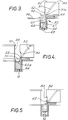
- the present invention provides a blade protection device which is illustrated in Figures 3 to 5. These figures are taken at a diagrammatic section along line III-III of Figure 1.
- a blade protection device 52 is mounted in an aperture in the cassette bay floor, forming part of the printing device 2 and denoted by reference numeral 56.
- the blade protection device 52 comprises a channel member defining a channel 54 and having a ledge 66 which is supported by the cassette bay floor 56.
- the blade protection device also includes a safety guard 58 having a body 60 and an upstanding blade protection part 62.
- Figure 3 illustrates the blade protection device in its operative position.
- the body 60 of the safety guard 58 is mounted on a shaft 67 slidable in an aperture 69 formed in the base of the channel 54. It is held in the upward position by a compression spring 64.
- Reference numeral 32 denotes the part of the tape clamp located on the left hand side of the cutter support in Figures 1 and 2.
- FIG 4 shows the case when a cassette 10 has been inserted into the cassette bay of the printing device.
- the cassette 10 carries a protrusion 70 on its underside which acts against the upper surface 60a of the body 60 of the safety guard to move it downwardly within the channel against the action of the compression spring 64. This thus moves the blade protection part 62 downwardly and allows the blade 30 to be moved forward to cut the tape.
- the blade protection device is designed so that the printer can only be used with correctly designed cassettes, namely, in this embodiment, cassettes having a protrusion capable of acting on the body of the safety guard to push it downwardly.
- Figure 5 shows the case where a cassette having a flat base is inserted. The body of the blade protection device is pushed down only part way, still preventing free movement of the blade. To prevent a user from pushing the blade protection device fully by other means, the blade protection part 62 is located in a recessed part 80 of the tape clamp 32 so that it is not accessible from above.
- the compression spring can be designed so that it is fully compressed at a height which is too great to allow the safety guard to be pressed fully downwardly by action on the upper surface of blade protection part 62 so as to prohibit free movement of the blade.
- FIG. 6 numerals representing like parts as the embodiment of Figures 3 to 5 are indicated by the same reference numerals, but primed.
- the embodiment of Figures 6 to 8 differs from the embodiment of Figures 3 to 5 in that the body 60' of the blade protection device has an upstanding blade protection part 62' which has a horizontal upper surface 63 which performs a similar function to 60a in Figure 4.
- the horizontal surface 63 can be actuated by the flat base 65 of a cassette 10'.
- the cassette is not required to have any depending part or protrusion such as that designated by reference numeral 70 in Figure 4.
- the blade protection device includes a second upstanding part 70 which is intended to extend through an aperture 72 in the base 65 of the cassette 10'.
- the arrows in Figure 6 illustrate that insertion and downward movement of the cassette 10' cause the body 60' of the blade protection device to be pushed downwardly against the action of the spring 64' to release the blade 30' for operation. To that extent, operation is similar to the embodiment of Figures 3 to 5.
- Figure 7 illustrates the cassette fully inserted into the machine in the ready-to-use position.
- Figure 8 illustrates what happens when an attempt is made to insert an incorrect cassette 10'', that is one without an aperture in its base equivalent to aperture 72. It is not possible to insert this cassette into the machine because the upstanding part 70 of the blade protection device will prevent the insertion. Thus, the machine will only operate with specially designed cassettes.
Description
- The present invention relates to tape cutting apparatus and is particularly but not exclusively concerned with a tape cutting apparatus used in thermal printing devices.
- Thermal printing devices of the type with which the present invention is primarily concerned operate with a supply of tape arranged to receive an image and a means for transferring an image onto the tape. In one form, a tape holding case holds a supply of image receiving tape and a supply of an image transfer ribbon, the image receiving tape and the transfer ribbon being passed in overlap through a printing zone of the printing device. A printing device operating with a tape holding case of this type is described for example in EP-A-0267890 (Varitronics, Inc.). Other printing devices have been made in which letters are transferred to an image receiving tape by a dry lettering or dry film impression process. In all of these printing devices, the construction of the image receiving tape is substantially the same. That is, it comprises an upper layer for receiving an image which is secured to a releaseable backing layer by a layer of adhesive. Once an image or message has been printed on the tape, it is desired to cut off that portion of the tape to enable it to be used as a label.
- Various cutting mechanisms have been disclosed for performing this function. In EP-A-0267890, cooperating scissor blades are used to cut off a portion of the tape. In EP-0322919, a blade mounted on a cutter support member is used to cut the tape, with the tape supported by an anvil. As described in EP-A-0364305 the anvil is provided by part of the cassette wall. The anvil can alternatively be part of the printing device or a separate component altogether. There have been found to be disadvantages relating to these cutting methods, and the present inventors have found that it is preferable to cut the tape using a blade which enters a slot below the tape rather than acting against an anvil. In this respect, reference is made to our copending Application No.94304284.6 (Page White & Farrer Ref. 75930) published as EP-A-0 634 275.
- When cutting a tape by moving a blade through the tape into a slot, it is advantageous if the blade is sharp and angled. Moreover, the blade remains sharp during the life of the printing device as it is not blunted by action against an anvil. Moreover, as the blade is required to travel through a distance through the tape and into the slot, it cannot be wholly concealed throughout its travel. Thus, the blade could possibly present a safety hazard. The present invention is intended to overcome any possible difficulties associated with having the blade exposed in the printing device.
- According to a first aspect of the present invention, there is provided a printing device in combination with a cassette holding a supply of tape, said cassette being removably received in a cassette receiving bay of the tape printing device, said printing device comprising a cutting blade for cutting said tape after printing, characterised in that said printing device further comprises a blade protection device comprising a blade protection member mounted for movement relative to the cutting blade so as to prevent movement of the blade in a first position and to allow movement of the blade in a second position, the blade protection member being movable between the first and second positions by insertion of the cassette into the cassette receiving bay.
- Preferably the blade protection member is mounted for movement in a channel member located in the floor of a cassette receiving bay so that the blade protection member protrudes above the floor in the first position and does not protrude above the floor in the second position. Preferably, the blade protection member lies flush with the floor in the second position.
- Preferably, the blade protection member is resiliently mounted within the channel member so that it is biased into the first position.
- In another embodiment, the blade protection member has an upstanding part which is pushed down by the base of a cassette. In this embodiment the blade protection member can have a second upstanding part which extends through an aperture in the base of a specially designed cassette. If an attempt is made to insert a cassette without such an aperture in its base, it will not be possible to do this because the second upstanding part will prevent the insertion.
- The blade protection device is preferably designed so that the protection member is not moved from the first to the second position except by insertion of a proper cassette.
- In one embodiment, the cassette has a depending part which locates a surface of the blade protection member and causes it to move against the action of a spring into the channel member.
- According to a second aspect of the present invention, there is provided a cassette intended for cooperation with a printing device having a cassette receiving bay, a cutting blade for cutting tape after printing and a blade protection device comprising a blade protection member mounted for movement relative to the cutting blade so as to prevent movement of the blade in a first position and to allow movement of the blade in a second position, the cassette comprising:
- a supply of tape;
- a wall over which the tape passes in use; and
- a base;
- a cutting location on said wall whereat a cutting blade can cut said tape;
- According to a third aspect of the present invention, there is provided a cassette intended for cooperation with a printing device having a cassette receiving bay, a cutting blade for cutting tape after printing and a blade protection device comprising a blade protection member mounted for movement relative to the cutting blade so as to prevent movement of the blade in a first position and to allow movement of the blade in a second position, the blade protection member including an upstanding member, said cassette comprising:
- a supply of tape; and
- a wall, over which the tape passes in use; and
- a base;
- a cutting location on said wall whereat a cutting blade can cut said tape;
- According to a fourth aspect of the present invention, there is provided a printing device comprising a cutting blade for cutting a print medium, characterised in that there is provided blade protection member mounted for movement relative to the cutting blade so as to prevent movement of the blade in a first position and to allow movement of the blade in a second position, the blade protection member being movable between the first and second positions.
- For a better understanding of the present invention and to show how the same may be carried into effect, reference will now be made by way of example to the accompanying drawings, in which:
- Figure 1 is a plan view illustrating a printing device for use with the present invention;
- Figure 2 shows the cutting mechanism in more detail;
- Figures 3 and 4 are cross-sections through a blade protection device in the first and second positions;
- Figure 5 is a cross-section through a blade protection device when actuated with an incorrect cassette;
- Figure 6 illustrates in section another embodiment of a blade protection device;
- Figure 7 illustrates in section the blade protection device of Figure 6 in the "in use" position; and
- Figure 8 illustrates the blade protection device of Figure 6 when an attempt to insert an incorrect cassette is made.
- Figure 1 illustrates in plan view a cassette bay of a printing device. The cassette bay is shown by the
dotted line 2. The cassette bay includes a thermal print head 4 and a platen 6 which cooperate to define a print location P in a manner which is known in the art. The print head 4 is pivotable about a pivot point 8 so that it can be brought into contact with the platen 6 for printing and moved away from the platen to enable a cassette to be removed and replaced. - A cassette inserted into the
cassette bay 2 is denoted generally byreference numeral 10. The cassette holds asupply spool 12 of image receiving tape 14 which comprises an image receiving layer secured to a backing layer by a layer of adhesive. The image receiving tape 14 is guided by a guide mechanism (which is not shown) through the cassette, out of the cassette through an outlet O, past the print location P to a cutting location C. Thecassette 10 also has an inkribbon supply spool 16 and an ink ribbon take upspool 18. Theink ribbon 20 is guided from the inkribbon supply spool 16 through the print location P and taken up on the ink ribbon take upspool 18. The image receiving tape 14 passes in overlap with theink ribbon 20 through the print location P with its image receiving layer in contact with the ink ribbon. - In the printing device illustrated in Figure 1, the platen 6 is driven so that it rotates to drive the image receiving tape 14 past the print location P during printing. In this way, tape is printed and fed out from the print location P to the cutting location C. In contrast to earlier devices, the cutting location C is provided at a location on a portion of the wall of the
cassette 10 which is close to the print location P. As the tape is fed out of the cassette by driving the platen 6, there is no need for a further feed mechanism for the tape and this enables the cutting location C to be closer to the print location P. In the described embodiment, the distance between the cutting location and the print location can be 9mm. The portion of the wall of thecassette 10 where the cutting location C is defined is denoted byreference numeral 22. Aslot 24 is defined in this wall portion and the image receiving tape 14 is fed past the print location P to the cutting location C where it is supported by facingwall portions slot 24. - The printing device includes a cutting mechanism denoted generally by
reference numeral 26. This cutting mechanism includes acutter support member 28 which carries ablade 30. The design of theblade 30 can be seen more clearly in Figures 3 and 4. Theblade 30 has a sharpened andangled cutting edge 31. Theblade 30 cuts the image receiving tape 14 and then enters theslot 24 with theleading part 31a of itsedge 31 first, rather than bearing against an anvil. - Figure 2 shows the
cutting mechanism 26 in more detail. The cutting mechanism comprises with the cutter support member 28 atape clamp 32. Thecutter support member 28 is mounted for movement within aslot 34 in thetape clamp 32. Theportion 22 of thecassette wall 10 defining the cutting location C has adjacent one of the facingsurfaces 22a a steppedportion 36 which cooperates with a steppedportion 38 in thetape clamp 32 in a manner which will be described more clearly hereinafter. A relativelyweak spring 40 is located between aledge 42 of thetape clamp 32 and a cooperatingledge 44 of thecasing 2. A relativelystiff spring 46 is located in arecess 48 of thetape clamp 32 to act against thecutter support member 28. The cutter support member provides a surface which is preferably formed in the shape of abutton 50 or the like and which can be depressed by a user using manual force. - As will be readily appreciated, when the tape is to be cut, the
button 50 is depressed, pushing theblade 30 towards the tape, through the tape to cut it and into theslot 24. When acassette 10 is inserted into theprinting device 2 the blade is not readily accessible and so does not present a safety hazard. However, when there is no cassette in the printing device, the blade can be exposed if thebutton 50 were to be inadvertently actuated, could present a safety hazard. Thus, the present invention provides a blade protection device which is illustrated in Figures 3 to 5. These figures are taken at a diagrammatic section along line III-III of Figure 1. - A
blade protection device 52 is mounted in an aperture in the cassette bay floor, forming part of theprinting device 2 and denoted byreference numeral 56. Theblade protection device 52 comprises a channel member defining achannel 54 and having aledge 66 which is supported by thecassette bay floor 56. The blade protection device also includes asafety guard 58 having abody 60 and an upstandingblade protection part 62. Figure 3 illustrates the blade protection device in its operative position. Thebody 60 of thesafety guard 58 is mounted on ashaft 67 slidable in anaperture 69 formed in the base of thechannel 54. It is held in the upward position by acompression spring 64. In this position, theblade protection part 62 is located against thetip 31a of theblade 30 to prevent actuation of the blade to bring it to an accessible position.Reference numeral 32 denotes the part of the tape clamp located on the left hand side of the cutter support in Figures 1 and 2. - Figure 4 shows the case when a
cassette 10 has been inserted into the cassette bay of the printing device. Thecassette 10 carries aprotrusion 70 on its underside which acts against theupper surface 60a of thebody 60 of the safety guard to move it downwardly within the channel against the action of thecompression spring 64. This thus moves theblade protection part 62 downwardly and allows theblade 30 to be moved forward to cut the tape. - The blade protection device is designed so that the printer can only be used with correctly designed cassettes, namely, in this embodiment, cassettes having a protrusion capable of acting on the body of the safety guard to push it downwardly. Figure 5 shows the case where a cassette having a flat base is inserted. The body of the blade protection device is pushed down only part way, still preventing free movement of the blade. To prevent a user from pushing the blade protection device fully by other means, the
blade protection part 62 is located in a recessedpart 80 of thetape clamp 32 so that it is not accessible from above. - As an alternative to this, the compression spring can be designed so that it is fully compressed at a height which is too great to allow the safety guard to be pressed fully downwardly by action on the upper surface of
blade protection part 62 so as to prohibit free movement of the blade. - Reference will now be made to Figures 6 to 8 to describe an alternative embodiment of the present invention. In Figures 6 to 8, numerals representing like parts as the embodiment of Figures 3 to 5 are indicated by the same reference numerals, but primed. The embodiment of Figures 6 to 8 differs from the embodiment of Figures 3 to 5 in that the body 60' of the blade protection device has an upstanding blade protection part 62' which has a horizontal
upper surface 63 which performs a similar function to 60a in Figure 4. However, as will readily be appreciated, thehorizontal surface 63 can be actuated by theflat base 65 of a cassette 10'. Thus, the cassette is not required to have any depending part or protrusion such as that designated byreference numeral 70 in Figure 4. - Nevertheless, it is still desirable to design the machine so that it can only receive specially designed cassettes. To that end, the blade protection device includes a second
upstanding part 70 which is intended to extend through anaperture 72 in thebase 65 of the cassette 10'. The arrows in Figure 6 illustrate that insertion and downward movement of the cassette 10' cause the body 60' of the blade protection device to be pushed downwardly against the action of the spring 64' to release the blade 30' for operation. To that extent, operation is similar to the embodiment of Figures 3 to 5. - Figure 7 illustrates the cassette fully inserted into the machine in the ready-to-use position.
- Figure 8 illustrates what happens when an attempt is made to insert an incorrect cassette 10'', that is one without an aperture in its base equivalent to
aperture 72. It is not possible to insert this cassette into the machine because theupstanding part 70 of the blade protection device will prevent the insertion. Thus, the machine will only operate with specially designed cassettes.
Claims (13)
- A printing device in combination with a cassette (10) holding a supply (12) of tape (14), said cassette (10) being removably received in a cassette receiving bay (2) of the tape printing device, said printing device comprising a cutting blade (30) for cutting said tape after printing, characterised in that said printing device further comprises a blade protection device (52) comprising a blade protection member (58) mounted for movement relative to the cutting blade (30) so as to prevent movement of the blade (30) in a first position and to allow movement of the blade (30) in a second position, the blade protection member (58) being movable between the first and second positions by insertion of the cassette (10) into the cassette receiving bay (2).
- A combination according to claim 1, wherein the blade protection member (62) is mounted for movement in a channel member (54) located in a floor (56) of the cassette receiving bay (2) so that the blade protection member (58) protrudes above the floor (56) in the first position and does not protrude above the floor (56) in the second position.
- A combination according to claim 2, wherein the blade protection member (58) lies flush with the floor (56) in the second position.
- A combination according to claim 2 or 3, wherein the blade protection member (58) is resiliently mounted within the channel member (54) so that it is biased into the first position.
- A combination according to any preceding claim, wherein the cassette has a depending part (70) which locates a surface (60a) of the blade protection member (58) and causes it to move against the action of a spring (64) into the channel member (54).
- A combination according any of claims 1 to 4 wherein the blade protection member (58) includes an upstanding part (70), and the cassette (10') has an aperture (72) for receiving said upstanding part (70) when the cassette (10') is inserted into the cassette receiving bay (2).
- A cassette (10) intended for cooperation with a printing device having a cassette receiving bay (2), a cutting blade (30) for cutting tape (14) after printing and a blade protection device (52) comprising a blade protection member (58) mounted for movement relative to the cutting blade (30) so as to prevent movement of the blade in a first position and to allow movement of the blade in a second position, the cassette (10) comprising:a supply (12) of tape (14);a wall over which the tape (14) passes in use; anda base;a cutting location (C) on said wall whereat a cutting blade (30) can cut said tape;characterised in that there is provided a depending part (70) which extends from said base in the region of the cutting location (C) so that, when the cassette (10) is inserted into the cassette receiving bay (2) of the printing device, the depending part (70) locates a surface (60a) of the blade protection member (58) and causes the blade protection member (58) to move against the action of a spring (64) between the first and second positions.
- A cassette (10') intended for cooperation with a printing device having a cassette receiving bay (2), a cutting blade (30) for cutting tape (14) after printing and a blade protection device (52) comprising a blade protection member (58) mounted for movement relative to the cutting blade (30) so as to prevent movement of the blade (30) in a first position and to allow movement of the blade (30) in a second position, the blade protection member (58) including an upstanding member (70), said cassette comprising:a supply (12) of tape (14); anda wall, over which the tape (14) passes in use; anda base;a cutting location (C) whereat a cutting blade (30) can cut said tape;characterised in that said base (65) is arranged to locate a surface (63) of the blade protection member (58) of the printing device to cause the blade protection member to move against the action of a spring (64') between the first and second positions when the cassette (10') is inserted into the cassette receiving bay (2), the cassette (10') further having an aperture (72) in said base (65) in the region of the cutting location (C) through which said upstanding member (70) extends.
- In combination, a cassette as claimed in claim 7 or 8 in combination with a printing device comprising a cassette receiving bay (2), a cutting blade (30) for cutting tape (14) after printing and a blade protection device (52) comprising a blade protection member (58) mounted for movement relative to the cutting blade (30) so as to prevent movement of the blade (30) in a first position and to allow movement of the blade (30) in a second position.
- A printing device comprising a cutting blade (30) for cutting a print medium (14), characterised in that there is provided blade protection member (58) mounted for movement relative to the cutting blade (30) so as to prevent movement of the blade (30) in a first position and to allow movement of the blade (30) in a second position, the blade protection member (58) being movable between the first and second positions.
- A printing device as claimed in claim 10, wherein said print medium is housed in a cassette and the blade protection member (58) is mounted for movement in a channel member (54) located in a floor (56) of a cassettte receiving bay (2) so that the blade protection member (58) protrudes above the floor (56) in the first position and does not protrude above the floor (56) in the second position.
- A printing device as claimed in claim 11, wherein the blade protection member (58) lies flush with the floor (56) in the second position.
- A printing device as claimed in claim 11 or 12, wherein the blade protection member (58) is resiliently mounted within the channel member (54) so that it is biased into the first position.
Applications Claiming Priority (2)
| Application Number | Priority Date | Filing Date | Title |
|---|---|---|---|
| GB9314388 | 1993-07-12 | ||
| GB939314388A GB9314388D0 (en) | 1993-07-12 | 1993-07-12 | Tape cutting apparatus |
Publications (3)
| Publication Number | Publication Date |
|---|---|
| EP0634278A2 EP0634278A2 (en) | 1995-01-18 |
| EP0634278A3 EP0634278A3 (en) | 1995-08-23 |
| EP0634278B1 true EP0634278B1 (en) | 1997-09-17 |
Family
ID=10738679
Family Applications (1)
| Application Number | Title | Priority Date | Filing Date |
|---|---|---|---|
| EP94304286A Expired - Lifetime EP0634278B1 (en) | 1993-07-12 | 1994-06-14 | Tape cutting apparatus |
Country Status (6)
| Country | Link |
|---|---|
| US (1) | US5501539A (en) |
| EP (1) | EP0634278B1 (en) |
| JP (1) | JP2925458B2 (en) |
| AU (1) | AU677059B2 (en) |
| DE (2) | DE69405661T2 (en) |
| GB (1) | GB9314388D0 (en) |
Families Citing this family (6)
| Publication number | Priority date | Publication date | Assignee | Title |
|---|---|---|---|---|
| US5853254A (en) * | 1994-12-15 | 1998-12-29 | Seiko Epson Corporation | Tape cartridge for use in a tape printer |
| AUPN323195A0 (en) * | 1995-05-29 | 1995-06-22 | Creative Products Pty Limited | Film wrap dispenser with serpentine path |
| KR100234589B1 (en) * | 1995-11-21 | 1999-12-15 | 야스카와 히데아키 | Printer having cutting apparatus and protective device for use in a printer |
| ES2149394T3 (en) * | 1996-03-07 | 2000-11-01 | Esselte Nv | MECHANISM THAT INDICATES THE PRESENCE OF A TAPE IN A TAPE PRINTING DEVICE. |
| JP3644152B2 (en) * | 1996-09-26 | 2005-04-27 | ブラザー工業株式会社 | Tape printer |
| ES2657592T3 (en) | 2011-03-03 | 2018-03-06 | Ntn Corporation | Status monitoring system for rolling device and threshold adjustment procedure for status monitoring system |
Citations (1)
| Publication number | Priority date | Publication date | Assignee | Title |
|---|---|---|---|---|
| US3895441A (en) * | 1972-02-07 | 1975-07-22 | Hobbs H Horak | Telescopic flick knife |
Family Cites Families (15)
| Publication number | Priority date | Publication date | Assignee | Title |
|---|---|---|---|---|
| US2913299A (en) * | 1956-11-29 | 1959-11-17 | Texas Instruments Inc | Recorder with combination latching and tearing assembly |
| US3237494A (en) * | 1963-07-09 | 1966-03-01 | Dashew Business Machines Inc | Tape cutoff with tab forming means |
| FR2098565A5 (en) * | 1970-07-10 | 1972-03-10 | Longo Bruno | |
| JPS5931958B2 (en) * | 1978-08-31 | 1984-08-06 | エルム工業株式会社 | Manual tape printer |
| JPS56144182A (en) * | 1980-04-09 | 1981-11-10 | Nec Corp | Blank cutter |
| JPS57107872A (en) * | 1980-12-24 | 1982-07-05 | Canon Inc | Apparatus with cutting mechanism |
| IT1162812B (en) * | 1983-01-11 | 1987-04-01 | Olivetti & Co Spa | POINT OF SALE PRINTER |
| US4537582A (en) * | 1983-10-04 | 1985-08-27 | Sanders Associates, Inc. | Plotter paper slitter |
| US4815874A (en) * | 1988-02-01 | 1989-03-28 | Kroy Inc. | Thermal printer and tape-ribbon cartridge with cut-off mechanism |
| JPH02106555A (en) * | 1988-10-14 | 1990-04-18 | Brother Ind Ltd | Tape containing cassette |
| US5188469A (en) * | 1988-10-14 | 1993-02-23 | Brother Kogyo Kabushiki Kaisha | Tape feed cassette with tape cutter and guide |
| US4907014A (en) * | 1989-05-18 | 1990-03-06 | Calcomp Inc. | Safely retracting paper-cutting apparatus for a roll paper printer |
| US5235887A (en) * | 1990-03-22 | 1993-08-17 | Citizen Watch Co., Ltd. | Cutter apparatus |
| JP2532387Y2 (en) * | 1990-12-06 | 1997-04-16 | ブラザー工業株式会社 | Tape cutting device |
| JP2985911B2 (en) * | 1992-01-08 | 1999-12-06 | ブラザー工業株式会社 | Tape cassette mounting structure in tape printer |
-
1993
- 1993-07-12 GB GB939314388A patent/GB9314388D0/en active Pending
-
1994
- 1994-06-14 EP EP94304286A patent/EP0634278B1/en not_active Expired - Lifetime
- 1994-06-14 DE DE69405661T patent/DE69405661T2/en not_active Expired - Lifetime
- 1994-06-14 DE DE0634278T patent/DE634278T1/en active Pending
- 1994-06-27 US US08/266,822 patent/US5501539A/en not_active Expired - Lifetime
- 1994-07-07 AU AU67329/94A patent/AU677059B2/en not_active Ceased
- 1994-07-12 JP JP6160243A patent/JP2925458B2/en not_active Expired - Fee Related
Patent Citations (1)
| Publication number | Priority date | Publication date | Assignee | Title |
|---|---|---|---|---|
| US3895441A (en) * | 1972-02-07 | 1975-07-22 | Hobbs H Horak | Telescopic flick knife |
Also Published As
| Publication number | Publication date |
|---|---|
| DE69405661T2 (en) | 1998-02-19 |
| JP2925458B2 (en) | 1999-07-28 |
| JPH0752479A (en) | 1995-02-28 |
| US5501539A (en) | 1996-03-26 |
| EP0634278A2 (en) | 1995-01-18 |
| AU6732994A (en) | 1995-01-19 |
| DE634278T1 (en) | 1996-01-18 |
| EP0634278A3 (en) | 1995-08-23 |
| GB9314388D0 (en) | 1993-08-25 |
| AU677059B2 (en) | 1997-04-10 |
| DE69405661D1 (en) | 1997-10-23 |
Similar Documents
| Publication | Publication Date | Title |
|---|---|---|
| EP0733482B1 (en) | A cassette for a thermal printer | |
| US5556213A (en) | Tape printer having a half-cut mechanism | |
| CA1179892A (en) | Printing apparatus and cartridge | |
| EP1082254B1 (en) | Hand-held label printer and cutting apparatus | |
| EP0899114B1 (en) | Printer for cutting media and method thereof | |
| AU666995B2 (en) | Tape cutting apparatus | |
| KR100395833B1 (en) | Half-cutting device and tape printing apparatus incorporating the same | |
| EP0634274A2 (en) | Printing apparatus | |
| EP0327073B1 (en) | Thermal printing device and tape supply cartridge therefor | |
| US5538591A (en) | Tape cutting apparatus | |
| EP0634278B1 (en) | Tape cutting apparatus | |
| US4754676A (en) | Computer paper guide edge shearer | |
| US5804023A (en) | Label cutting and applying apparatus | |
| JPH0546925Y2 (en) | ||
| JPH09314938A (en) | Cutting device | |
| EP0634277B1 (en) | Tape cutting apparatus | |
| US5718528A (en) | Cutting mechanism | |
| EP1935656B1 (en) | Printing apparatus | |
| AU677665B2 (en) | Tape cutting apparatus | |
| JP4696552B2 (en) | Cutter mechanism and tape processing apparatus having the same | |
| JP2001322323A (en) | Continuous form cutter | |
| JPS6040272A (en) | Printer | |
| JPH09208114A (en) | Pressure-sensitive tape cutter | |
| JPS6325956B2 (en) | ||
| JPH10193711A (en) | Printer |
Legal Events
| Date | Code | Title | Description |
|---|---|---|---|
| PUAI | Public reference made under article 153(3) epc to a published international application that has entered the european phase |
Free format text: ORIGINAL CODE: 0009012 |
|
| AK | Designated contracting states |
Kind code of ref document: A2 Designated state(s): DE FR GB IT |
|
| ITCL | It: translation for ep claims filed |
Representative=s name: BARZANO' E ZANARDO MILANO S.P.A. |
|
| EL | Fr: translation of claims filed | ||
| PUAL | Search report despatched |
Free format text: ORIGINAL CODE: 0009013 |
|
| AK | Designated contracting states |
Kind code of ref document: A3 Designated state(s): DE FR GB IT |
|
| 17P | Request for examination filed |
Effective date: 19950916 |
|
| DET | De: translation of patent claims | ||
| RAP1 | Party data changed (applicant data changed or rights of an application transferred) |
Owner name: ESSELTE N.V. |
|
| 17Q | First examination report despatched |
Effective date: 19960827 |
|
| GRAG | Despatch of communication of intention to grant |
Free format text: ORIGINAL CODE: EPIDOS AGRA |
|
| GRAH | Despatch of communication of intention to grant a patent |
Free format text: ORIGINAL CODE: EPIDOS IGRA |
|
| GRAH | Despatch of communication of intention to grant a patent |
Free format text: ORIGINAL CODE: EPIDOS IGRA |
|
| GRAA | (expected) grant |
Free format text: ORIGINAL CODE: 0009210 |
|
| AK | Designated contracting states |
Kind code of ref document: B1 Designated state(s): DE FR GB IT |
|
| PG25 | Lapsed in a contracting state [announced via postgrant information from national office to epo] |
Ref country code: IT Free format text: LAPSE BECAUSE OF FAILURE TO SUBMIT A TRANSLATION OF THE DESCRIPTION OR TO PAY THE FEE WITHIN THE PRE;WARNING: LAPSES OF ITALIAN PATENTS WITH EFFECTIVE DATE BEFORE 2007 MAY HAVE OCCURRED AT ANY TIME BEFORE 2007. THE CORRECT EFFECTIVE DATE MAY BE DIFFERENT FROM THE ONE RECORDED.SCRIBED TIME-LIMIT Effective date: 19970917 |
|
| REF | Corresponds to: |
Ref document number: 69405661 Country of ref document: DE Date of ref document: 19971023 |
|
| ET | Fr: translation filed | ||
| PLBE | No opposition filed within time limit |
Free format text: ORIGINAL CODE: 0009261 |
|
| STAA | Information on the status of an ep patent application or granted ep patent |
Free format text: STATUS: NO OPPOSITION FILED WITHIN TIME LIMIT |
|
| 26N | No opposition filed | ||
| REG | Reference to a national code |
Ref country code: GB Ref legal event code: IF02 |
|
| REG | Reference to a national code |
Ref country code: FR Ref legal event code: CD |
|
| PGFP | Annual fee paid to national office [announced via postgrant information from national office to epo] |
Ref country code: DE Payment date: 20130627 Year of fee payment: 20 Ref country code: GB Payment date: 20130627 Year of fee payment: 20 |
|
| PGFP | Annual fee paid to national office [announced via postgrant information from national office to epo] |
Ref country code: FR Payment date: 20130702 Year of fee payment: 20 |
|
| REG | Reference to a national code |
Ref country code: DE Ref legal event code: R071 Ref document number: 69405661 Country of ref document: DE |
|
| REG | Reference to a national code |
Ref country code: GB Ref legal event code: PE20 Expiry date: 20140613 |
|
| PG25 | Lapsed in a contracting state [announced via postgrant information from national office to epo] |
Ref country code: GB Free format text: LAPSE BECAUSE OF EXPIRATION OF PROTECTION Effective date: 20140613 |
|
| PG25 | Lapsed in a contracting state [announced via postgrant information from national office to epo] |
Ref country code: DE Free format text: LAPSE BECAUSE OF EXPIRATION OF PROTECTION Effective date: 20140617 |