EP0633384A2 - Blind apparatus - Google Patents
Blind apparatus Download PDFInfo
- Publication number
- EP0633384A2 EP0633384A2 EP94304904A EP94304904A EP0633384A2 EP 0633384 A2 EP0633384 A2 EP 0633384A2 EP 94304904 A EP94304904 A EP 94304904A EP 94304904 A EP94304904 A EP 94304904A EP 0633384 A2 EP0633384 A2 EP 0633384A2
- Authority
- EP
- European Patent Office
- Prior art keywords
- head box
- stopper
- cord
- tilter
- slats
- Prior art date
- Legal status (The legal status is an assumption and is not a legal conclusion. Google has not performed a legal analysis and makes no representation as to the accuracy of the status listed.)
- Granted
Links
- 230000000452 restraining effect Effects 0.000 claims abstract description 3
- 238000003780 insertion Methods 0.000 claims description 44
- 230000037431 insertion Effects 0.000 claims description 44
- 230000033001 locomotion Effects 0.000 claims description 37
- 230000003449 preventive effect Effects 0.000 claims description 31
- 125000006850 spacer group Chemical group 0.000 claims description 22
- 230000002093 peripheral effect Effects 0.000 claims description 4
- 230000002265 prevention Effects 0.000 claims description 3
- 230000000149 penetrating effect Effects 0.000 claims description 2
- 238000010276 construction Methods 0.000 description 14
- 230000002829 reductive effect Effects 0.000 description 9
- 230000000903 blocking effect Effects 0.000 description 7
- 230000000717 retained effect Effects 0.000 description 7
- 239000002184 metal Substances 0.000 description 6
- 230000004048 modification Effects 0.000 description 6
- 238000012986 modification Methods 0.000 description 6
- 230000007423 decrease Effects 0.000 description 4
- 238000000034 method Methods 0.000 description 4
- 238000005452 bending Methods 0.000 description 3
- 230000005540 biological transmission Effects 0.000 description 3
- 239000000463 material Substances 0.000 description 3
- 230000003213 activating effect Effects 0.000 description 1
- 230000003247 decreasing effect Effects 0.000 description 1
- 230000001419 dependent effect Effects 0.000 description 1
- 230000002542 deteriorative effect Effects 0.000 description 1
- 238000010586 diagram Methods 0.000 description 1
- 230000005489 elastic deformation Effects 0.000 description 1
- 230000002708 enhancing effect Effects 0.000 description 1
- 238000005192 partition Methods 0.000 description 1
- 239000000758 substrate Substances 0.000 description 1
- 230000003313 weakening effect Effects 0.000 description 1
- 238000004804 winding Methods 0.000 description 1
Images


Classifications
-
- E—FIXED CONSTRUCTIONS
- E06—DOORS, WINDOWS, SHUTTERS, OR ROLLER BLINDS IN GENERAL; LADDERS
- E06B—FIXED OR MOVABLE CLOSURES FOR OPENINGS IN BUILDINGS, VEHICLES, FENCES OR LIKE ENCLOSURES IN GENERAL, e.g. DOORS, WINDOWS, BLINDS, GATES
- E06B9/00—Screening or protective devices for wall or similar openings, with or without operating or securing mechanisms; Closures of similar construction
- E06B9/24—Screens or other constructions affording protection against light, especially against sunshine; Similar screens for privacy or appearance; Slat blinds
- E06B9/26—Lamellar or like blinds, e.g. venetian blinds
- E06B9/28—Lamellar or like blinds, e.g. venetian blinds with horizontal lamellae, e.g. non-liftable
- E06B9/30—Lamellar or like blinds, e.g. venetian blinds with horizontal lamellae, e.g. non-liftable liftable
- E06B9/32—Operating, guiding, or securing devices therefor
- E06B9/324—Cord-locks
-
- E—FIXED CONSTRUCTIONS
- E06—DOORS, WINDOWS, SHUTTERS, OR ROLLER BLINDS IN GENERAL; LADDERS
- E06B—FIXED OR MOVABLE CLOSURES FOR OPENINGS IN BUILDINGS, VEHICLES, FENCES OR LIKE ENCLOSURES IN GENERAL, e.g. DOORS, WINDOWS, BLINDS, GATES
- E06B9/00—Screening or protective devices for wall or similar openings, with or without operating or securing mechanisms; Closures of similar construction
- E06B9/24—Screens or other constructions affording protection against light, especially against sunshine; Similar screens for privacy or appearance; Slat blinds
- E06B9/26—Lamellar or like blinds, e.g. venetian blinds
- E06B9/28—Lamellar or like blinds, e.g. venetian blinds with horizontal lamellae, e.g. non-liftable
- E06B9/30—Lamellar or like blinds, e.g. venetian blinds with horizontal lamellae, e.g. non-liftable liftable
- E06B9/303—Lamellar or like blinds, e.g. venetian blinds with horizontal lamellae, e.g. non-liftable liftable with ladder-tape
- E06B9/306—Lamellar or like blinds, e.g. venetian blinds with horizontal lamellae, e.g. non-liftable liftable with ladder-tape with tilting bar along which the raising cords are guided
-
- E—FIXED CONSTRUCTIONS
- E06—DOORS, WINDOWS, SHUTTERS, OR ROLLER BLINDS IN GENERAL; LADDERS
- E06B—FIXED OR MOVABLE CLOSURES FOR OPENINGS IN BUILDINGS, VEHICLES, FENCES OR LIKE ENCLOSURES IN GENERAL, e.g. DOORS, WINDOWS, BLINDS, GATES
- E06B9/00—Screening or protective devices for wall or similar openings, with or without operating or securing mechanisms; Closures of similar construction
- E06B9/24—Screens or other constructions affording protection against light, especially against sunshine; Similar screens for privacy or appearance; Slat blinds
- E06B9/26—Lamellar or like blinds, e.g. venetian blinds
- E06B9/28—Lamellar or like blinds, e.g. venetian blinds with horizontal lamellae, e.g. non-liftable
- E06B9/30—Lamellar or like blinds, e.g. venetian blinds with horizontal lamellae, e.g. non-liftable liftable
- E06B9/303—Lamellar or like blinds, e.g. venetian blinds with horizontal lamellae, e.g. non-liftable liftable with ladder-tape
- E06B9/307—Details of tilting bars and their operation
-
- E—FIXED CONSTRUCTIONS
- E06—DOORS, WINDOWS, SHUTTERS, OR ROLLER BLINDS IN GENERAL; LADDERS
- E06B—FIXED OR MOVABLE CLOSURES FOR OPENINGS IN BUILDINGS, VEHICLES, FENCES OR LIKE ENCLOSURES IN GENERAL, e.g. DOORS, WINDOWS, BLINDS, GATES
- E06B9/00—Screening or protective devices for wall or similar openings, with or without operating or securing mechanisms; Closures of similar construction
- E06B9/24—Screens or other constructions affording protection against light, especially against sunshine; Similar screens for privacy or appearance; Slat blinds
- E06B9/26—Lamellar or like blinds, e.g. venetian blinds
- E06B9/28—Lamellar or like blinds, e.g. venetian blinds with horizontal lamellae, e.g. non-liftable
- E06B9/30—Lamellar or like blinds, e.g. venetian blinds with horizontal lamellae, e.g. non-liftable liftable
- E06B9/32—Operating, guiding, or securing devices therefor
- E06B9/323—Structure or support of upper box
-
- E—FIXED CONSTRUCTIONS
- E06—DOORS, WINDOWS, SHUTTERS, OR ROLLER BLINDS IN GENERAL; LADDERS
- E06B—FIXED OR MOVABLE CLOSURES FOR OPENINGS IN BUILDINGS, VEHICLES, FENCES OR LIKE ENCLOSURES IN GENERAL, e.g. DOORS, WINDOWS, BLINDS, GATES
- E06B9/00—Screening or protective devices for wall or similar openings, with or without operating or securing mechanisms; Closures of similar construction
- E06B9/24—Screens or other constructions affording protection against light, especially against sunshine; Similar screens for privacy or appearance; Slat blinds
- E06B9/26—Lamellar or like blinds, e.g. venetian blinds
- E06B9/28—Lamellar or like blinds, e.g. venetian blinds with horizontal lamellae, e.g. non-liftable
- E06B9/30—Lamellar or like blinds, e.g. venetian blinds with horizontal lamellae, e.g. non-liftable liftable
- E06B9/32—Operating, guiding, or securing devices therefor
- E06B9/326—Details of cords, e.g. buckles, drawing knobs
-
- E—FIXED CONSTRUCTIONS
- E06—DOORS, WINDOWS, SHUTTERS, OR ROLLER BLINDS IN GENERAL; LADDERS
- E06B—FIXED OR MOVABLE CLOSURES FOR OPENINGS IN BUILDINGS, VEHICLES, FENCES OR LIKE ENCLOSURES IN GENERAL, e.g. DOORS, WINDOWS, BLINDS, GATES
- E06B9/00—Screening or protective devices for wall or similar openings, with or without operating or securing mechanisms; Closures of similar construction
- E06B9/56—Operating, guiding or securing devices or arrangements for roll-type closures; Spring drums; Tape drums; Counterweighting arrangements therefor
- E06B9/68—Operating devices or mechanisms, e.g. with electric drive
- E06B9/76—Operating devices or mechanisms, e.g. with electric drive using crank handles
-
- E—FIXED CONSTRUCTIONS
- E06—DOORS, WINDOWS, SHUTTERS, OR ROLLER BLINDS IN GENERAL; LADDERS
- E06B—FIXED OR MOVABLE CLOSURES FOR OPENINGS IN BUILDINGS, VEHICLES, FENCES OR LIKE ENCLOSURES IN GENERAL, e.g. DOORS, WINDOWS, BLINDS, GATES
- E06B9/00—Screening or protective devices for wall or similar openings, with or without operating or securing mechanisms; Closures of similar construction
- E06B9/24—Screens or other constructions affording protection against light, especially against sunshine; Similar screens for privacy or appearance; Slat blinds
- E06B9/26—Lamellar or like blinds, e.g. venetian blinds
- E06B9/28—Lamellar or like blinds, e.g. venetian blinds with horizontal lamellae, e.g. non-liftable
- E06B2009/285—Means for actuating a rod (being tilt rod or lift rod)
-
- E—FIXED CONSTRUCTIONS
- E06—DOORS, WINDOWS, SHUTTERS, OR ROLLER BLINDS IN GENERAL; LADDERS
- E06B—FIXED OR MOVABLE CLOSURES FOR OPENINGS IN BUILDINGS, VEHICLES, FENCES OR LIKE ENCLOSURES IN GENERAL, e.g. DOORS, WINDOWS, BLINDS, GATES
- E06B9/00—Screening or protective devices for wall or similar openings, with or without operating or securing mechanisms; Closures of similar construction
- E06B9/24—Screens or other constructions affording protection against light, especially against sunshine; Similar screens for privacy or appearance; Slat blinds
- E06B9/26—Lamellar or like blinds, e.g. venetian blinds
- E06B9/28—Lamellar or like blinds, e.g. venetian blinds with horizontal lamellae, e.g. non-liftable
- E06B9/30—Lamellar or like blinds, e.g. venetian blinds with horizontal lamellae, e.g. non-liftable liftable
- E06B9/32—Operating, guiding, or securing devices therefor
- E06B9/322—Details of operating devices, e.g. pulleys, brakes, spring drums, drives
- E06B2009/3222—Cordless, i.e. user interface without cords
Definitions
- the present invention relates to a blind apparatus which is suspended on a wall or the like of a room and which can be hoisted up or down arbitrarily. More particularly, the present invention relates to a horizontal type blind in which a plurality of slats are supported horizontally by means of a ladder cord hung from a head box at a distance between respective upper and lower slats and in which lifting cords fit to a bottom rail disposed at the bottommost of the slats are introduced upward through the slats and then introduced into the head box, the lifting cords being further introduced within the head box horizontally toward one end of the head box, and in which the slats are lifted up or down by pulling or loosening the lifting cords and turned by moving up or down vertical cords located before and after the aforementioned ladder cord.
- Horizontal type blind apparatuses of the aforementioned type have been widely used.
- the horizontal type blinds enable the user to lift up or down the slats and adjust the slat angle easily. It is also possible to suspend the slats at a desired height by fastening the lifting cords at a desired position by means of a stopper device.
- a rotating operation rod for rotating the slats is disposed near one end of the head box, and one end of the lifting cord is passed through the rotating operation rod and introduced downward from the bottom thereof.
- the slats are rotated by means of the rotating operation rod and lifted up or down by means of the lifting cords.
- a stopper device which holds the motion of the lifting cords is incorporated near one end of the head box in order to fasten the lifting cords at a desired position.
- the conventional stopper devices for such blind apparatus have the following problems. That is, because the locking metal piece is provided on the grip, an operating load is applied to the operation rod when the slats are lifted up or down. Thus, it is necessary to provide an operation rod having a large diameter in order to obtain sufficient strength, thus the size of the operation unit increases.
- a stopper device which has a conical portion having a U-shaped cross section capable of holding the lifting up or down of by nipping the lifting cords in cooperation with the tapered portion of the differential drum, and the lifting cords introduced from the head box are inserted through the hollow operating handle and then led out of the bottom of the operating handle. Additionally, one end of a stopper releasing cord which is capable of releasing the fastening of the lifting cords is connected to the stopper.
- one end of the stopper releasing cord is introduced from the bottom of the stopper into the conical portion and a knot is formed in order to contain the knot of the stopper releasing cord within the conical portion.
- the other end of the stopper releasing cord is inserted through the operating handle and introduced out from the bottom end of the operating handle.
- the differential drum includes the function for transmitting the rotation of the operating handle to the rotation shaft as well as a stopper
- the internal space of the differential drum is increased and the size of the differential drum is increased.
- the play of the lifting cord is increased.
- the differential drum and the stopper rotate integrally or relatively to each other, the lifting cords are likely to be twined.
- the stopper cannot be assembled beforehand because of the construction reasons, the workability of the assembly is low.
- the conical portion of the stopper because the knot formed in the stopper releasing cord is contained in the conical portion of the stopper, the diameter of the conical portion must be increased.
- the conical portion must be formed so as to have a U-shaped cross section.
- a stopper device which is capable of locking the lifting up or down of the lifting cords is provided within the head box.
- the lifting cords are inserted through the operation handle and connected to different positions of the lifting operation knob which is rotatable with the operation handle, so that the slats can be lifted up or down.
- the bottom end of the releasing cord which is capable of operating the stopper mechanism is inserted through the operation handle and connected to the releasing operation knob which is rotatable with the operation handle, so that the slats can be lifted up or down.
- the releasing operation knob is pulled down, the stopper mechanism is released, so that the slats descend.
- the aforementioned conventional blind apparatus has the following problems. That is, when the slats are rotated, if the operation handle is turned, the lifting operation knob and the releasing operation knob rotate integrally therewith. Thus, the lifting cords and the releasing cord are twined within the operation handle.
- Japanese Utility Model Laid-Open No. 57-99094 has disclosed an example in which the lifting cords are prevented from being twined. Namely, the bottom ends of the lifting cords which droop from the stopper mechanism provided at the bottom of the rotating operation rod are inserted through respective insertion holes provided on the knob having the same number of insertion holes as the number of the lifting cords and then connected with each other.
- this system prevents the lifting cords introduced from the bottom end of the rotating operation rod from being twined, because the stopper mechanism is provided at the bottom end of the rotating operation rod.
- this system is utilized in an apparatus which includes a stopper mechanism within the head box, it is not possible to prevent the lifting cords from being twined within-the operation handle.
- the aforementioned matter is the second problem of the conventional blind apparatus.
- a universal joint is utilized.
- bifurcated pieces are provided on each end of a hollow driving shaft and a hollow driven shaft and both bifurcated pieces are pivotally connected by a hollow connecting piece.
- Both bifurcated pieces and the connecting piece are pivotally connected by fitting a protrusion of each connecting point of the connecting piece into a receiving hole formed at each connecting point of each bifurcated piece.
- Both bifurcated pieces and the connecting piece are pivotally connected so that the center lines of the aforementioned shafts and a line connecting the respective connecting points of the connecting piece and the bifurcated pieces pass through the center of the connecting piece.
- the aforementioned conventional blind apparatus has the following problem. That is, because the driving shaft, the driven shaft, the bifurcated piece and the connecting piece are hollow, the bifurcated pieces are bent by a downward load applied to the operation rod, so that the protrusions of the connecting piece are disengaged from the receiving holes of the bifurcated pieces.
- a washer is attached to the tip of the protrusion of the connecting piece in order to prevent the protrusions of the connecting pieces from being disengaged from the receiving holes of the bifurcated pieces.
- a washer must be attached to every protrusion, the work necessary for this treatment is very troublesome.
- the device which inclines all the slats all at once to adjust the light shielding is called a tilter.
- the tilter of the conventional blind apparatus contains, for example, a worm gear for transmitting the rotation of the rotating operation rod to a transmission shaft and a worm wheel and some types of the apparatus contain the tilter which is provided within the head box located at the top end of the rotating operation rod.
- the lifting cord is inserted through the rotating operation rod.
- the tilter of the conventional blind apparatus has the following problem. Namely, when the slats are rotated by rotating the rotating operation rod, if the slats are lifted halfway and the rotating operation rod with the lifting cord introduced from the bottom of the rotating operation rod being hung on a cord hanger is rotated, the lifting cord within the rotating operation rod is twined. For this reason, a repellant force which tries to untwine the lifting cord is caused so that the rotating shaft rotates. Thus, it is not possible to maintain the slats in a desired condition.
- the tilter utilizes braking force which occurs between the worm gear and the worm wheel in order to prevent the rotation shaft from being forced to rotate due to the aforementioned repellant force and an external force applied to the slat.
- the actual gear ratio is set to a relatively high value. For this reason, it is necessary to rotate the rotating operation rod by five - six turns in order to tilt the slats by 180 degrees.
- a safety device having a substantially T-shaped cross section, which has a disk shaped head at one end of the thread portion is fixed to the rotating operation rod and the grip and the lifting cords are wound around the safety devices.
- T-shaped hooks protrude at two positions which are located at a predetermined distance along the length of the rotating operation rod and the lifting cords are wound around the hooks.
- the rotation operation bar of the conventional blind apparatus has the following problem. That is, in the apparatuses disclosed in Japanese Utility Model Laid-Open No. 56-70091 and Japanese Patent Laid-Open No. 61-56383, the lifting cords are only wound around the hook having a substantially T-shaped cross section, which protrudes sideways from the rotating operation rod or the grip. Thus, when the slats are blown by the wind or the rotating operation rod is rotated with the condition in which the blind apparatus is descended halfway and the lifting cord is wound around the hook, the lifting cord is unwound from the hook.
- a pair of lifting cords are disposed near both ends of the blind apparatus.
- a larger load is applied to lifting cords which pass in the center of the slats by a bottom rail and slats.
- the lifting cord stopper device which fastens the lifting cords to stop the blind fastens all the lifting cords with equal force, the lifting cords which are applied with the largest load and which pass in the center of the slats are likely to slip even when the stopper fastens the lifting cords, so that the lifting cord stopper device cannot fasten the lifting cords which pass near the center of the slats.
- the center portions of the slats and the bottom rail droop so that the level condition of the slats and the bottom rail cannot be maintained.
- the blind apparatuses of the aforementioned types are fixed to a wall or the like of a room through a bracket.
- the respective edges of both sides are bent inward and the head box is mounted on brackets by hooking the edges of both sides on hooking pieces of the brackets.
- the head box contains a rotating drum to which one end of the ladder cord supporting the slats is connected so that the ladder cord can be wound or rewound, a tilter which transmits the rotation of the rotating operation rod to the rotating drum and mechanical parts such as a stopper capable of holding the motion of the lifting cords for lifting up or down the slats.
- the aforementioned conventional blind apparatuses have the following problem. Because the mechanical parts are in contact with some locations of the edge portions of the head box, the brackets must be mounted at positions which no mechanical parts are fit to. Thus, when brackets are mounted on a window frame or the like, it is necessary to set the mounting positions of the brackets so as to avoid an interference between the mechanical parts and the brackets.
- the brackets can be attached freely to any positions of the head box without taking into account the positions of the mechanical parts, the edge portions of the head box protrude outward, so that the width of the bracket must be increased. Thus, the appearance of the head box is deteriorated. This is also one of the problems which must be solved in conventional blind apparatuses.
- the blind bracket disclosed therein comprises a substantially L-shaped supporting frame fit to a window frame and an engaging member detachable from the supporting frame.
- a cut-out dented portion is formed at the bottom of the beginning end of its level portion and a upward facing dented portion is formed at the front end of the level portion.
- the engaging member is supported by a supporting frame so that the engaging member is movable back and forth.
- an engaging protrusion is formed at a position which corresponds to the cut-out dented portion when the engaging member is inserted into the supporting frame completely, and a locking piece and a locking tongue are formed at a position which corresponds to the engaging dented portion.
- the top edge of one side of the box (otherwise called head box) is nipped between the cut-out dented portion and the engaging protrusion and fixed.
- the top edge of the other side is nipped between the locking tongue and the locking piece, the locking tongue and the locking piece sliding beyond the top edge thereof, in order to hold the right/left movement of the head box.
- the top edge of the other side is nipped between the locking tongue and the engaging dented portion in order to restrict the up/down motion of the head box, thereby fixing the head box to the brackets.
- the engaging protrusion which supports the bottom of the top edge of one side of the head box is moved so that the top edge is released from being supported.
- the locking tongue goes beyond the top edge of the other side, so that seizing of the top edge in the right/left direction and in the upward direction is eliminated.
- the head box can be removed from the bracket.
- the blind apparatus of the aforementioned type in a narrow space, for example, between double sashes or between a sash and a Japanese sliding paper door.
- a narrow space for example, between double sashes or between a sash and a Japanese sliding paper door.
- the bracket does not protrude.
- the bracket which can meet such a demand comprises a supporting member mounted on the top surface of the top mounting space and a locking member mounted horizontally rotatably with respect to the supporting member.
- a locking portion which is locked on a locking protruded edge formed inside of the top edge of the groove type head box is formed on the locking member.
- Japanese Patent Laid-Open no. 40-34054 has disclosed the following type of the device for fixing a blind apparatus or a curtain supporting frame.
- This device comprises a supporting frame in which protruding edges which direct inward are formed at the top ends on both side walls and a groove is formed between the protruding edges and a fixing device in which a circular rise-up entering the groove of the supporting frame is formed on both sides of a substrate, in which a protruding edge engaging with the bottom faces of both protruding edges of the supporting frame is formed on the ends, in which handles are provided in succession between both protruding edges and in which a nail hole is formed in the center thereof.
- the fixing device is nailed on the upper beam of a partition of a room, window or the like so that the device is freely rotatable.
- the bent pieces of the supporting frame are hooked on both protruding edges.
- Japanese Patent Laid-Open no. 63-106893 has disclosed a blind apparatus fixing metal piece in which engaging edges are formed by bending inward the top edges of the groove type frame and the engaging edges of the frame are engaged therewith by rotating the lever to fix the frame, the fixing metal piece being constructed so that the engaging member which is engaged between the bottom of the frame and the engaging edge is supported so as to be rotatable and that a lever for rotating the engaging member is connected to the engaging member.
- Japanese Patent Laid-Open No. 63-173497 has disclosed a blind fixing metal piece in which engaging edges are formed by bending inward the top edges of a groove type frame and the engaging edges of the frame are engaged therewith by rotating the operation lever, the fixing metal piece being constructed so that a shaft from which the operation lever originates is supported on one end of the supporting member so as to be rotatable, the supporting member being provided with a locking portion for supporting one engaging edge of the frame, one side of the shaft being provided with a locking groove which is locked on the other engaging edge according to the rotation of the operation lever.
- an object of the present invention is to provide a blind apparatus having an improved stopper device.
- a blind apparatus comprising: a head box; a bracket having retaining portions for retaining both longitudinal side edges of the head box so as to enable mounting of the head box; a series of vertically spaced slats arranged substantially in parallel with one another and supported by ladder cords; a bottom rail under the series of slats; a rotary drum disposed inside the head box, each the ladder cords being connected to the rotary drum so as to be wound and rewound on and from the drum; a tilter input shaft extended downward from one end of the head box and rotatable to cause tilting of the slats; a tilter disposed in the head box, for transmitting the rotation of the tilter input shaft to the rotary drum; a hollow rotating operation rod coupled to the tilter input shaft through a universal joint; a hollow grip provided at the lower end of the rotating operation rod; lifting cords connected at their one ends to a bottom rail and extended through holes formed in the series of
- Another object of the present invention is to provide a blind apparatus having an improved operating arrangement capable of preventing twining of lifting cords.
- a blind apparatus wherein the grip is rotatable integrally with the rotating operation rod and movable up and down relative to the rotating operation rod by a predetermined amount, the grip having a bore through which the lifting cords are extended for movement up and down, a twining preventive ring being attached to the grip for vertical movement integrally with id grip and for rotation relative to the grip, whereby the stopper can be released by mans the stopper release cord as a result of rotation and relative movement of the grip.
- Still another object of the present invention is to provide a blind apparatus having an improved operating arrangement which eliminates undesirable disengagement of the components and which can easily be assembled.
- a blind apparatus wherein the universal joint includes: a first bifurcated piece having a pair of branches projecting axially from one end of the tilter input shaft so as to oppose to each other, each the branch having a first pin receiving hole; a second bifurcated piece having a pair of branches projecting axially from one end of the tilter input shaft so as to oppose to each other, each the branch having a second pin receiving hole; and a hollow interconnecting piece having connecting pins rotatably received in the first and second pin receiving holes so as to interconnect the tilter input shaft and the rotating operation rod such that the tilter input shaft and aid rotating operation rod are rotated as a unit with each other while changing the angle formed therebetween; wherein the connecting pins interconnecting aid tilter input shaft and the interconnecting piece are provided on their heads with protruding portions which protrude in the direction of axis of the interconnecting piece, the first pin-receiving holes in the
- a further object of the present invention is to provide a blind apparatus having an improved tilter.
- a blind apparatus wherein the tilter has a torque adding device which poses additional rotational torque such that a grater torque is required for causing the tilter shaft to start to rotate than that required after the tilter shaft has been started to rotate.
- a still further object of the present invention is to provide a blind apparatus having an improved rotating operation rod or a grip.
- a blind apparatus wherein the rotating operating rod comprises a pair of hooks spaced from each other in the axial direction, each of the hooks being capable of holding a lifting cord wound thereon, each the hook including: a connecting portion which can be attached to aid rotating operation rod and a T-shaped protruding portion having two wing portions projecting laterally from the connecting portion; one of the two wing portions of the T-shaped protruding portion and the connecting portion form therebetween a groove-like clamping portion, the hooks being arranged such that their clamping portions oppose each other.
- a yet further object of the present invention is to provide a blind apparatus employing three or more lifting cords, improved to prevent drooping of the slats at the mid portion of the blind apparatus so as to maintain all the slats correctly in horizontal posture.
- a blind apparatus wherein at least three lifting cords are used, characterized in that the central lifting cord, after being introduced into the head box, turns around a guide roller to extend away from the stopper device and then turned around a turning roller so as to be introduced into the stopper device.
- a yet further object of the present invention is to provide a blind apparatus having an improved mounting structure.
- a blind apparatus wherein the upper end edges of side walls of the head box are bent inward to oppose each other so as to form a mounting surface, and the rotary drum and the stopper device are fixed in the head box by means of spacers such that the levels of the rotary drum and the stopper device are below the level of the lower end of the retaining portions of the bracket, the spacers being shaped in conformity with the configurations of the bent upper edges of the head box so that their upper ends may not contact with the retaining portions of the bracket.
- a yet further object of the present invention is to provide a blind apparatus having an improved mounting bracket.
- the bracket comprises a supporting frame, a retainer member and an urging member, the supporting frame having a vertical portion by means of which the supporting frame is secured to a wall or the like and a horizontal portion which is connected to the vertical portion orthogonally thereto, the retaining portion including a retaining tab formed on the horizontal portion of the supporting frame and capable of retaining one side of the head box, and a retaining projection formed on the retainer member so as to retain the other side of the head box; the horizontal portion including retaining portions formed on the free end thereof, and supporting shelves for supporting the retainer member such that the retainer member is movable into and out of the supporting frame, the retainer member including a spring portion for normally urging the retainer member into the supporting frame, a retaining projection formed on the lower face of the retainer member, guide grooves for guiding the urging member when the urging member is moved into and out of the supporting frame, a retaining portion provided on ends
- a yet further object of the present invention is to provide a blind apparatus which is suitable for mounting in a restricted space such as, for example, a space between two sashes of a double-sash arrangement.
- a blind apparatus wherein the bracket comprises: a rotary member having retaining portions on both lateral sides thereof; and a supporting member for rotatably supporting the rotary member such that the rotary member is rotatable within a horizontal plane between a retaining position where the retaining portions of the rotary member retain both side edges of aid head box and a release position where the retaining portions of the rotary member release the side edges of the head box, the supporting member being capable of being fixed in a restricted space between a pair of shield members which are movable between and open positions, the rotary member including an operating lever formed integrally therewith, for causing rotation of the rotary member within a horizontal plane relative to the supporting member, the operating lever being provided at its front end with a bent portion which abuts a side wall of the head box when the rotary member is in the head box retaining position and a release prevention portion which projects by an amount substantially the same as the amount of projection of the bent portion, at the leading
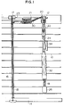
- Fig. 1 shows an embodiment of the blind apparatus of the present invention.
- a plurality of slats 10 are arranged vertically at a predetermined distance.
- a head box 12 is disposed at the top end of ten rows of these slats and a bottom rail 14 is disposed at the bottom end.
- a ladder cord 16 is provided between the head box 12 and the bottom rail 14 to support the respective slats 10.
- the top end of the ladder cord 16 is connected to a rotating drum 17 which is rotatably provided within the head box 12 so that the ladder cord can be wound or released.
- the inclination angle of the slat 10 can be changed by the rotation of the rotating drum 17.
- a hollow tilter input shaft 22 is introduced from one end of the head box 12 and a hollow rotating operation rod 24 having a hollow grip 32 which is disposed at the bottom end thereof is rotatably connected to the bottom end of the tilter input shaft 22.
- the rotation of the rotating operation rod 24 is transmitted to a tilter 20 provided near one end of the head box 12 through the tilter input shaft 22.
- the rotation received by the tilter 20 rotates the rotating drum 17 which is connected to the rotating shaft 23 through the rotating shaft 23.
- One ends of the lifting cords 18 are connected to the bottom rail 14 and the other ends thereof are introduced into the head box 12 through insertion holes (not shown) which are provided on slats 10.
- the other-ends thereof are passed through a stopper device 21 provided near one end of the head box 12, introduced through the tilter input shaft 22, the rotating operation rod 24 and the grip 32, and then are connected to the knob 26 which is disposed on the bottom of the grip 32 so that the lifting cords 18 can ascend or descend.
- the stopper device 21 is capable of holding the motion of the lifting cords 18.
- One end of a stopper releasing cord 30 which is capable of releasing the holding of the lifting cords 18 are connected to the stopper device 21.
- the other end of the stopper releasing cord 30 is passed through the tilter input shaft 22 and the rotating operation rod 24, and then connected to the grip 32.
- the rotating operation rod 24 is provided with a cord hanger 34 on which the lifting cords 18 introduced from the bottom of the rotating operation rod 24 are hung.
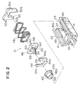
- Fig. 2 shows a disassembly perspective view of the stopper device 21.
- the stopper device 21 comprises a stopper case 40, a cord nozzle 42, a cord nozzle stopping member 44, a cord stopper 46, a spring (elastic body) 48, and a cord stopper blocking member 50.
- the stopper case 40 is a substantially rectangular shape having an opening at the top.
- Protruded rails 41 are formed on the inside surface near the edge of both walls except near the right ends.
- Further protruded loosening preventive members 43 are formed on the protruded rails 41 from a predetermined position along the length of the rails 41 up to the right ends shown in Fig. 2.
- Engaging holes 45 are formed near the right ends of both walls, the engaging holes being near the protruded rails 41.
- Hole portions 47 are formed at two positions (one of them is not shown here) of the bottom of the stopper case 40 so that the holes 47 are on the same position along the length thereof.
- a cord nozzle supporting hole 52 for supporting the cord nozzle 42 is formed at the left end of the stopper case 40 as shown in Fig. 2.
- the cord nozzle 42 comprises a small-diameter portion 42a which can be fit to the cord nozzle supporting hole of the stopper case 40 and a large-diameter portion 42b.
- the cord nozzle 42 has a nozzle hole 56 which allows the lifting cord 18 to pass therethrough and in which the cord stopper 46 is to be inserted to fasten the lifting cord 18.
- a substantially U-shaped cutout portion 59 is formed in the cord nozzle stopping member 44.
- a protruding portion 44a which can be fit in a hole (not shown) formed on the bottom of the stopper case 40 is formed on the bottom of the cord nozzle stopping member 44.
- Protruding portions 44b, 44c which can engage with the protruded rails of the stopper case 40 are formed on both sides of the cord nozzle preventing member 44.
- the cord stopper 46 comprises a substantially square pole bottom 58 and a conical end 54 which protrudes therefrom.
- the cord stopper 46 has a plurality of lifting cord insertion holes which allow the lifting cords 18 to pass therethrough, the insertion hole being formed on the bottom of the cord stopper and disposed at a predetermined distance around the conical end.
- the cord stopper 46 contains a first insertion hole 62 (see Fig. 4) which is bored from the bottom 58 to the circumference of the conical end 54 and a second insertion hole 64 which is bored on the bottom near the first insertion hole 62 on the circumference of the conical end 54.
- the first insertion hole 62 and the second insertion hole 64 allow the stopper releasing cords 30 to pass therethrough.
- a guiding groove 68 for guiding the motion of the lifting cord is formed on the external surface of the conical end at a position corresponding to a lifting cord insertion hole 60 on the bottom 58.
- a spring 48 is formed in the shape of a square and has almost the same size as the bottom 58 of the cord stopper 46.
- the cord stopper blocking member 50 is formed in a substantially U-shape.
- the cord stopper blocking member 50 has protruding portions 50a, 50b which can engage with the hole portions 47 of the stopper case 40, the protruding portions being formed on the ends of both side walls, and it has protruding portions 50c, 50d which can engage with the engaging holes 45 of the stopper case, the protruding portions being formed on the sides of both walls.
- the respective parts are formed of materials having a strength suitable therefor. As a result, the durability of the respective parts can be enhanced.
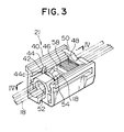
- the assembly method of the stopper device will be described according to a perspective view of the stopper device shown in Fig. 3 and a sectional view thereof shown in Fig. 4.
- the cord nozzle 42 is inserted from the top of the stopper case 40 and the small-diameter portion 42a of the cord nozzle 42 is fit to the cord nozzle supporting hole 52 of the stopper case 40.
- the cord nozzle stopping member 44 is inserted from the top of the stopper case 40 and the protruding portion 44a of the cord nozzle stopping member 44 is fit to the hole (not shown) on the bottom of the stopper case 40.
- the protruding portions 44b, 44c of the cord nozzle stopping member 44 are engaged with a groove disposed below the protruded rails 41 of the stopper case 40. Consequently, the large-diameter portion 42b of the cord nozzle 42 is nipped between the cord nozzle supporting hole 52 of the stopper case 40 and the cord nozzle stopping member 44 so as to fasten the cord nozzle 42.
- the cord stopper 46 is inserted from the right end shown in Fig. 3, of the stopper case 40.
- the cord stopper 46 is blocked from moving upward by means of the loosing preventive member 43, so that the cord stopper 46 does not slip out of the top of the stopper case 40.
- One end of the stopper releasing cord 30 is inserted from the bottom 58 through the first insertion hole 62 and introduced out of the circumference of the conical end 54.
- the end of the stopper releasing cord 30 is introduced from the second insertion hole 64 to a side opposite to the side in which the conical end 54 of the bottom 58 is formed.
- a knot loose preventive means
- the lifting cords 18 are introduced into the stopper case 40 through the cord nozzle supporting hole 52 of the stopper case 40 and inserted through the nozzle hole 56 of the cord nozzle 42 and then through the cutout portion 59 of the cord nozzle stopping member 44. Finally, the cords are introduced through the guiding groove 68 of the cord stopper 46 and led out of the lifting cord insertion hole 60.
- the cord stopper 46 is pressed to the left in the stopper case 40 so as to insert the conical end 54 into the nozzle hole 56 of the cord nozzle 42.
- the spring 48 is inserted from the right end of the stopper case 40, as shown in Fig. 3, with the lifting cord and the stopper releasing cord 30 being inserted through the internal space of the spring 48.
- the cord stopper blocking member 50 is inserted from the top of the stopper case 40 with the lifting cord 18 and the stopper releasing cord 30 being inserted through the internal space of the cord stopper blocking member 50.
- the protruding portions 50a, 50b thereof are embedded into the hole portions 47 of the stopper case 40 and the protruding portions 50c, 50d thereof are engaged with the engaging holes 45 of the stopper case 40. Consequently, the spring 48 is prevented from loosing from the right end of the stopper case 40 by means of the cord stopper blocking member 50.
- the cord stopper 46 is always pressed toward the cord nozzle 42.
- the conical end 54 of the cord stopper 46 is fit to the nozzle hole 56 of the cord nozzle 42 so that the lifting cord 18 is nipped therebetween.
- the lifting cords 18 are fastened by the cord stopper 46 due to a friction caused by engagement between the cord stopper 46 and the lifting cord 18, so that the lifting cord 18 is firmly held.
- the knob 26 or the lifting cord 18 introduced from the bottom of the grip 32 is held and pulled downward. Then, the lifting cord 18 is guided by means of the guiding groove 68 of the cord stopper 46 and pulled to the right in Fig. 5. Due to friction caused between the lifting cord 18 and the cord stopper 46, the cord stopper 46 is slightly moved to the right in Fig. 5 resisting the elastic force of the spring 48. Consequently, the fastening between the nozzle hole 56 of the cord nozzle 42 and the conical end 54 of the cord stopper 46 is released thereby weakening the force of nipping the lifting cord between the nozzle hole 56 and the conical end 54, so that it is possible to further continue to pull down the lifting cord 18. Thus, the slats 10 can be lifted up.
- the knob 26 or the lifting cord 18 is released from the hand.
- the force of pulling the lifting cord 18 to the right in Fig. 5 is released so that the cord stopper 46 is pressed to the cord nozzle 42 by means of the elastic force of the spring 48.
- the conical end 54 of the cord stopper 46 is fastened to the nozzle hole 56 of the cord nozzle 42 so that the lifting cord 18 is nipped therebetween. Due to friction caused by the engagement between the cord stopper 46 and the lifting cord 18, the cord stopper 46 fastens further the lifting cords 18, thereby blocking the lifting cords 18 from moving. As a result, it is possible to stop the slats 10 at a predetermined position.
- the spring 48 is utilized as an elastic member.
- the elastic member is not restricted to the spring, but it is permissible to use other elastic member, for example, rubber.
- the stopper case which is open at the top is fixed to the head box and a cord stopper is fit to the stopper case so that the stopper cannot rotate relative to the stopper case but can move along the length thereof.
- a conical end capable of nipping the lifting cords between the conical end and the cord nozzle so that the lifting cords cannot be moved, is formed on the cord stopper and the stopper releasing cord is inserted from the bottom of the cord stopper through the conical end, and then introduced out of the external surface of the conical end.
- the lifting cord is introduced to a side opposite to the conical end and a loosening preventive knot is formed to connect the lifting cord to the cord stopper.
- the stopper case and the cord stopper are both rotatable and the size of the stopper case can be decreased, thereby making it possible to decrease a space between the stopper case and the cord stopper. Then, it is possible to prevent the lifting cords from being twined. Additionally, it is possible to reduce the size of the stopper apparatus.
- the top portion of the stopper case is open, parts can be assembled to the stopper case from the top. Because the assembly can be achieved by only fixing the stopper case to the head box, the assembly work is easy.
- the diameter of the conical end can be reduced and the configuration of the conical end can be formed in a conical shape. Consequently, the lifting cords can be firmly nipped between the conical end of the cord stopper and the cord nozzle, and thus it is possible to actuate the stopper device securely.
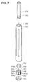
- FIG. 7 - 9 Another embodiment of the present invention will be described with reference to Figs. 7 - 9.
- This embodiment contains a grip having an improved construction. Because the entire construction of the blind apparatus is the same as described in Figs. 1 - 6, the description thereof is omitted.
- Fig. 7 shows a disassembly perspective view of a construction near a grip 32
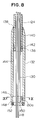
- Fig. 8 shows a sectional view thereof.
- the cross section of a rotating operation rod 124 is hexagonal and a small-diameter portion 136 having a smaller diameter than the portion having the hexagonal cross section is formed near the bottom end.
- a stepped portion 140 is formed at the lower end of the insertion hole 138 within the grip 132 and the diameter of the stepped portion 140 is larger along the diameter than the insertion hole 138.
- a space portion 144 to which a first loosening preventive ring 142 can be fit so that the ring can move vertically relative to the stepped portion is formed.
- a stepped portion 146 is formed at the bottom of the internal space of the grip 132, and the stepped portion 146 has a larger diameter than the space portion 144.
- a twining preventive ring 148 can be fit to this portion so that the ring is freely rotatable.
- a groove portion 152 to which a second loosening preventive ring 150 can be fit is formed along the circumference at the bottom of the position in which the twining preventive ring 148 in the grip 132 is disposed.
- Parts of the circumference of the first loosening preventive ring 142 and the second loosening preventive ring 150 are cut off.
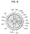
- four through holes 154, 156, 158, 160 are formed along the length thereof at a predetermined distance along the circumference. Of these holes, three through holes 154, 156, 158 are formed so as to be large enough for the respective lifting cord 118 to pass through.
- the insertion hole 160 is as large as the stopper releasing cord 130 can pass therethrough.
- a through hole 162 through which the stopper releasing cord 130 can be inserted is formed at a position near the outside circumference relative to the through hole 162 of the twining preventive ring 148.
- Slits 154a, 156a, 158a, 162a are formed from the respective through holes 154, 156, 158, 162 to the circumference of the twining preventive ring 148.
- the bottom end of the rotating operation is inserted into the insertion hole 138 of the grip 132.
- the first loosening preventive ring 142 is fit to the small-diameter portion 136 of the rotating operation rod 124.
- the grip 132 is prevented from slipping out of the rotating operation bar 124 by first loosening preventive ring's being in contact with the stepped portion 140.
- the stopper 121 is activated, as shown in Fig. 4, the first loosening preventive ring 142 is located downward of the stepped portion 40 due to tension which raises the stopper releasing cord 130, so that the first loosening preventive ring 142 is not in contact with the stepped portion 140.
- the twining preventive ring 148 is fit to the bottom portion of the grip 132 so that the ring 148 is freely rotatable. The top end of the twining preventive ring 148 is in contact with the stepped portion 146 so that the ring 148 is blocked from moving upward.
- the second loosening preventive ring 150 is embedded in the groove portion 152 of the grip 132, so that the twining preventive ring 148 is blocked from moving downward.
- the lifting cord is introduced from the rotating operation rod, passed through the space portion 144 of the grip 132 and through the through holes 154, 156, 158 of the twining preventive ring 148, and finally introduced from the bottom of the grip 132.
- the cord 130 is inserted through the space portion 144 of the grip 132 and the through hole 160 of the twining preventive ring 148.
- the cord 130 is bent at the bottom of the twining preventive ring 148 toward the through hole 162, introduced from the top end of the through hole 162 and then the knot 130a is formed at the end of the cord 130 and contained in the large-diameter portion 164.
- the knot 130a of the stopper releasing cord 130 is prevented from slipping out of the through hole 162.
- the grip 132 When the inclination angle of the slats 110 is changed, the grip 132 is held by hand and revolved. Consequently, the rotating operation rod 124 rotates integratedly with the grip 132, so that the revolution of the rotating operation rod 124 is transmitted to the rotating drum 117 which rotates integratedly with the rotating shaft 123 by means of the tilter 120 through the tilter input shaft 122, in order to revolve the rotating drum 117. Thus, the inclination angle of the slats 110 is changed. Because even if the grip 132 is revolved, the twining preventive ring 148 which is fit thereto so as to be freely rotatable is not revolved, the lifting cords 118 and the stopper releasing cord 130 are not revolved neither. Thus, the lifting cords and the stopper releasing cord 130 are not twined.
- connection of the grip 132 and the rotating operation rod 124 is achieved by first loosening preventive ring 142's being in contact with the stepped portion 140 of the grip 132, it is easy to install the grip 132 to the rotating operation rod 124.
- the grip is colored in the same color system as the slats, even when the rotating operation rod is transparent, various demands can be met by preparing grips of a predetermined number of color types and combining a grip of a demanded color with the rotating operation rod, thereby reducing stock risk.
- the stopper releasing cord 130 does not protrude from the bottom of the grip 132, thereby not deteriorating the appearance.
- slits 154a, 156a, 158a, 162a on the twining preventive ring 148 so that they extends from the respective through holes 154, 156, 158, 162 to the circumference thereof, it is possible to facilitate insertion of the lifting cords 118 and the stopper releasing cord 130 through the respective through holes 154, 156, 158, 162.
- the present embodiment contains a universal joint having an improved construction. Because the entire construction of the blind apparatus can be substantially the same as described in Figs. 1 - 6, the description thereof is omitted.
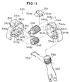
- Fig. 10 shows a disassembly perspective drawing of a universal joint 228.
- the universal joint 228 comprises first bifurcated pieces 222a, 222b of the tilter input shaft 222, second bifurcated pieces 254a, 254b of the rotating operation rod 224 and a connecting piece 240.
- the connecting piece 240 has connecting pins 242, 244, 246, 248 which protrude from the circumference by every 90 degrees.
- Protruding portions 242a, 246a which extend along the axial direction of the connecting piece 240 are formed at the heads of two connecting pins 242, 246 located symmetrically relative to each other, of the connecting piece 240.
- No protruding portion or slant face is formed on the connecting pins 244, 248 of the connecting piece 240.
- the tilter input shaft 222 has the first bifurcated pieces 222a, 222b disposed at bottom positions which face each other so that the bifurcated pieces 222a, 222b protrude along the axis of the tilter input shaft 222.
- the first bifurcated pieces 222a, 222b have first pin receiving holes 250, 252, respectively, which allow the connecting pins 242, 246 of the connecting piece to be fit thereto so that the connecting piece 240 is freely rotatable, the diameter of the first pin receiving holes being increased in the form of a cone as the circumference is approached.
- the rotating operation rod 224 has a hollow connecting member 254 having second bifurcated pieces 254a, 254b which are disposed at positions facing each other, the bifurcated pieces protruding along the length of the rotating operation rod 224.
- the second bifurcated pieces 254a, 254b contain second pin receiving holes 256, 258 which allow the connecting pins 244, 248 of the connecting piece 240 to be fit thereto so that the connecting pins are freely rotatable.
- the assembly of the universal joint 228 is achieved by fitting the connecting pins 244, 248 of the connecting piece 240 into the second pin receiving holes 256, 258 of the rotating operation rod 224 and further by fitting the connecting pins 242, 246 into the first pin receiving holes 250, 252 of the tilter input shaft 222.
- the connecting pins 242, 246 of the connecting piece 240 are fit into the first pin receiving holes 250, 252 of the tilter input shaft 222, the connecting pins 242, 246 are easy to be fit into the first pin receiving holes 250, 252 because slant surfaces 242b, 246b are formed on the connecting pins 242, 246.
- the protruding portions which protrude along the axis of the connecting piece are formed at the heads of the connecting pins of the connecting piece which is connected with the tilter input shaft. Then, the first pin receiving holes in which the diameter thereof increases in the form of a cone as the circumference is approached are formed in the first bifurcated pieces of the tilter input shaft. Then, the connecting pins having a protruding portion at the head are fit into the first pin receiving holes in order to connect the connecting piece to the tilter input shaft.
- the connecting pin is not loose from the first pin receiving hole unless a washer or the like is attached to the tip of the connecting pin, the assembly of the universal joint is easy thereby enhancing workability. Additionally, because slant surface is formed on a side opposite to the protruding portion, of the head of connecting pin in which the protruding portion is formed, it becomes further easy to fit the connecting pins into the first pin receiving holes, thereby further improving efficiency of the work.
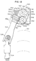
- FIG. 11 to 17 contains a modified tilting mechanism. Because the entire construction of the blind apparatus is substantially the same as described in Figs. 1 to 6, the description thereof is omitted.
- One end of the stopper releasing cord 330 shown in Fig. 12 capable of releasing the holding of the lifting cord 318 is connected to the stopper.
- the other end of the stopper releasing cord 330 is connected to the grip 332 through the tilter shaft 322 and the rotating operation rod 324.
- Fig. 11 shows a disassembly perspective view of the tilter 320.
- the tilter 320 comprises a tilter shaft 322, tilter cases 342, 344, first and second worm wheels (worm wheels) 346, 348, a ball 350, a torque applying device 352 and a cord guide 354.
- a hollow worm 356 which can mesh with the second worm wheel 348 is formed at the top of the tilter shaft 322 so that the hollow worm 356 is integrated with the tilter shaft 322.
- the tilter cases 342, 344 include the first and second space portions 342a, 342b and 344a, 344b to which the first and second worm wheels 346, 348 can be fit so as to be rotatable.
- Insertion holes 342c, 344c in which the rotating shaft 323 can be inserted so as to be rotatable and which rotatably supports the first worm wheel 346, the insertion holes going through the respective walls, are formed in the first space portions 342a, 344a.
- a connecting supporting portion 342d which supports the second worm wheel 348 so as to be rotatable and which can be fit to a connecting hole 344d formed so as to pass through the wall of the second space portion 344b protrudes in the second space portion 342b.
- the tilter cases 342, 344 contain the third space portions 342e, 344e which are capable of supporting the worm 356.
- Groove portions 342g, 344g in which the torque applying device 352 can be inserted are formed below the third space portions 342e, 344e shown in Fig. 11, of the tilter cases 342, 344.
- Dented portions 342f, 344f to which the cord guide 354 can be fit are formed on the top portions of the tilter cases 342, 344.
- An insertion hole 346a having a hexagonal cross section is formed in the rotation center of the first worm wheel 346.
- the rotating shaft 323 having a hexagonal cross section can be fit into the insertion hole 346a so as to be integrally rotatable with the first worm wheel.
- An insertion hole 348a which the connecting supporting portion 342d can be fit into is formed in the rotation center of the second worm wheel 348 and the second worm wheel is rotatably supported by means of the connecting supporting portion 342d as described above.
- the torque applying device 352 is constructed by means of a substantially U-shaped spring both ends of which are slightly deflected outward.
- the cord guide 354 comprises circular shaped guiding portions 354 for guiding the motion of the lifting cords 318 and a connecting portion 354b which is embedded to the dented portions 342f, 344f of the tilter cases 342, 344.
- Fig. 12 shows the tilter 320 which is mounted on the head box 312.
- a tilter case 342 is mounted on a fixing member 358 provided on the inside wall of the head box 312. Consequently, the tilter case 342 is fixed to the head box 312.
- the tilter case 344 is also treated in the same manner as for the tilter case 342 although the representation thereof is omitted.
- the first worm wheel 346 is disposed in the first space portion 342a of the tilter case 342 through a ball 350.
- the rotating shaft 323 inserted from the insertion hole 342c of the tilter case 342 is fit into the insertion hole 346a of the first worm wheel 346 so that the rotating shaft rotates integrally with the first worm wheel.
- the second worm wheel 348 is disposed so that the connecting supporting portion 342d is inserted through the insertion hole 348a of the second worm wheel 348.
- the first worm wheel 346 meshes with the second worm wheel 348 in order to transmit driving force therebetween.
- a worm 356 is engaged with the second worm wheel 348 in order to transmit a rotation force to the second worm wheel.
- the worm 356 is rotatably supported by the third space portions 342e, 344e of the tilter cases 342, 344, respectively.
- the torque applying device 352 is mounted on the portion of the tilter shaft 322 disposed within the tilter case 342 below the worm 356 by inserting the tilter shaft 322 into the U-shaped space portion of the torque applying device to elastically nip the tilter shaft therewith.
- the torque applying device 352 which is mounted on the tilter shaft 322 is inserted into the groove portions 342g, 344g of the tilter cases 342, 344 and both end portions thereof are arranged so as to face the bottom of the tilter case 342 as shown in Fig. 13.
- the cord guide 354 is fit to the dented portions 342f, 344f of the tilter cases 342, 344.
- the lifting cords 318 are disposed on the guide portion 354a of the cord guide 354 so that the cords are movable.
- the lifting cords 318 go through the worm 356, the tilter shaft 322 and the rotating operation rod 324 so that the cords 318 are movable.
- the rotating torque applied to the tilter shaft 322 increases to reach a large value as shown in Fig. 15 after the left end of the torque applying device in Fig. 14 is hooked on the bottom surface of the tilter case 342 until the torque applying device 352 is forced so as to expand.
- the rotating torque of the tilter shaft 322 after the torque applying device 352 is expanded decreases and is maintained at a small value as shown in Fig. 15. That is, a braking force is applied to the tilter shaft 322 just when the rotation of the tilter shaft starts and after the rotation of the tilter shaft has started, not so large braking force is applied thereto.
- the lifting cords which pass through the internal space thereof may be sometimes twisted.
- a untwisting force is applied to the tilter shaft 322 so that this force is tempted to rotate the rotating shaft 323.
- the force tempted to rotate the rotating shaft 323 is larger than the braking force applied to the tilter shaft 322 when the rotation thereof starts, the rotating shaft 323 is not revolved.
- the torque applying device is constructed by using a substantially U-shaped spring-both ends of which are deflected slightly outward
- the present invention is not restricted to this embodiment.
- a circular spring both ends of which are deflected slightly outward as shown in Fig. 16 can be used or a substantially circular spring in which part of both ends thereof is intersected and in which the both ends are deflected slightly outward can be also used.
- a torque applying device in which a large rotating torque is needed when the rotation of the tilter shaft is started and in which the rotation can be attained by a smaller rotating torque after the rotation of the tilter shaft has started as compared with when the rotation thereof is started, is provided at the tilter shaft.
- a braking force is applied to the tilter shaft when the rotation of the tilter shaft is started. Due to external force applied to the slats such as the wind pressure or a repellant force which is caused when the rotating operation rod is revolved if the lifting cords are inserted through the rotating operation rod, the worm and the worm wheel are blocked from being revolved, so that the rotation of the rotating shaft is hindered. Thus, the slats are not inclined accidentally so that it is possible to maintain the blind in a desired condition.
- FIG. 18 A further embodiment of the present invention will be described with reference to Figs. 18 to 20.
- the present embodiment has a modified hook device on which the lifting cords are hung. Because the entire construction of the blind apparatus may be substantially the same as described in Figs. 1 to 6, the detailed description thereof is omitted.
- one end of the lifting cord 418 is connected to the bottom rail 414 and the other end thereof is inserted through the insertion holes (not shown) disposed on the slats 410, introduced into the head box 412 and introduced out near one end of the head box 412. Then, the lifting cord passes through the rotating operation rod 424 and the grip 432 and is connected to the knob 426 disposed at the bottom of the grip 432 so that the lifting cord can be lifted up or down.
- the rotating operation rod 424 has two hooks 434, 436 on which the lifting cords 418 introduced from the bottom end of the rotating operation rod 424 can be hung, the hooks being provided at two positions which are located at two positions vertically apart from each other.
- the hook 434 comprises a linking portion 434a which can be attached to the rotation operation rod 424 by elastic deformation and a T-shaped protruding portion 434b which protrudes from the side of the linking portion 434a.
- a nipping portion 434c which is a groove having a width smaller than the diameter of the lifting cord 418 is formed between the protruding portion 434b (one side piece) which protrudes downward of the T shape and the linking portion 434a.
- the gap between the protruding portion 434b which protrudes upward and the linking portion 434a is formed so as to be larger than the diameter of the lifting cord 418.
- a groove-like nipping portion 436c having a gap narrower than the diameter of the lifting cord 418 is formed between the T-shaped protruding portion 436b (one side piece) which protrudes upward of the hook 436 and the linking portion 436a.
- a gap between the protruding portion 436b which protrudes downward and the linking portion 436a is formed so as to be larger than the diameter of the lifting cord 418.
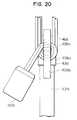
- Fig. 19 shows the hooks 434, 436 on which the lifting cords 418 are hung.
- the lifting cords 418 introduced from the bottom end of the grip 432 are wound on the protruding portion 434b which protrudes upward of the hook 434 and the protruding portion 436b which protrudes downward of the hook 436.
- one ends of the lifting cords are wound around the nipping portion 436c of the hook 436. Because the gap of the nipping portion 436c is smaller than the diameter of the lifting cord 418 as described above, the lifting cords 418 wound around the nipping portion 436c are nipped elastically and held by the nipping portion 436c. Consequently, the lifting cords 418 are not unwound easily.
- the ends of the lifting cords 418 are wound around the protruding portion 434b which protrudes upward of the hook 434 after the lifting cords are wound on the nipping portion 434c or the mounting position of the hook 434 is adjusted because the hook 434 can be elastically attached to the rotating operation rod 424.
- the hook comprises a linking portion attachable to the rotating operation rod and a T-shaped protruding portion which protrudes sideways of the linking portion.
- One piece of the T-shaped portion of the protruding portion and the linking portion form a groove-like nipping portion capable of nipping the lifting cord.
- the lifting cords are nipped elastically by the nipping portion by winding the ends of the lifting cords wound from one hook to another hook around the nipping portion, the lifting cords are elastically nipped by the nipping portion in order to prevent the lifting cords from being unwound from the hook easily.
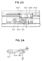
- FIG. 21 to 24 A still further embodiment of the present invention will be described with reference to Figs. 21 to 24.
- the present embodiment is preferably applicable to a blind apparatus which is horizontally long and the lifting cords are employed at three or more positions along the length of the apparatus including the center portion of the apparatus.
- the slippage of the lifting cord connected to the center portion of the blind apparatus, bearing the largest load of three or more lifting cords used in such a large size blind apparatus, relative to a stopper device, is eliminated to prevent the center portion of the slats from drooping.
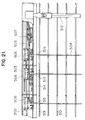
- Fig. 21 shows a horizontal type blind apparatus according to the present invention.
- reference numeral 501 designates a slat
- numeral 502 designates a head box
- numeral 503 designates a ladder cord which support a plurality of slats at a vertical distance
- numeral 504 designates a lifting cord
- numeral 505 designates a rotating shaft which revolves the slats
- numeral 506 designates a rotating drum disposed on the rotating shaft.
- the ladder cord 503 is wound around the rotating drum 6, and by revolving the rotating shaft 505, the ladder cord 503 is moved vertically along the length thereof to revolve the slats in order to adjust light shielding. Because such mechanism is well known, the detailed description thereof is omitted.
- the bottom ends of the lifting cords 504 are connected to the bottom rail (not shown) disposed at the bottommost of the slats 1, the lifting cords are introduced through the slats, then introduced into the head box 502 and led horizontally within the head box to one end thereof.
- the lifting cord stopper device 507 which holds the motion of the lifting cord 504 is contained at one end of the head box.
- the lifting cord stopper device 507 comprises a cord nozzle 508, a cord stopper 509 and a spring 510 which elastically presses the cord stopper against the cord nozzle in order to fasten the lifting cord 504 between the cord nozzle and the cord stopper, thereby holding the slats at a desired position.
- the stopper releasing cord 511 is mounted on the cord stopper 509. The stopper releasing cord 511 releases the lifting cord 504 by separating the cord stopper 509 from the cord nozzle 508 resisting the force of the spring 510 in order to allow the slats to descend by its own weight.
- the rotating operation rod 512 for revolving the slats is provided and the top end of the rotating operation rod 512 is connected to the rotating shaft 505 through a universal joint. By revolving the rotating operation rod 512, the rotating shaft 5 is revolved to revolve the slats.
- the lifting cords 4 are introduced horizontally within the head box and passed through the lifting cord stopper device 7, the lifting cords 4 are introduced through the rotating operation rod 12 and extended downward from the rotating operation rod 12.
- the slats are revolved by operating the rotating operation rod 12, and the slats 1 are lifted up or down by the lifting cord 4 extending downward from the rotating operation rod 12.
- the lifting cord 4 In the horizontal type blind apparatus, three lifting cords 4 are provided.
- the lifting cord stopper device fastens all the lifting cords with an equal force by fastening the lifting cords to stop the blind apparatus, the lifting cord passing in the center of the slats, which is loaded with the largest load is likely to slip even when the stopper device fastens the lifting cords.
- the lifting cord stopper device sometimes cannot fasten the lifting cord which passes near the center of the slats.
- the lifting cord disposed in the center is introduced into the head box, the lifting cord is led in a direction opposite to the aforementioned lifting cord stopper device, wound around the direction reversing roller and led to the lifting cord stopper device.
- the lifting cord 4 is passed through the guiding roller 13 disposed in the center of the head box, led in a direction opposite to the lifting cord stopper device 7 and wound around the direction reversing roller 14.
- the lifting cord is led to the lifting cord stopper device 7, introduced through the lifting cord stopper device 7 and led through the rotating operation rod 12.
- Reference numeral 15 designates the guiding roller for guiding a lifting cord 4 other than the aforementioned lifting cords.
- the lifting cord 4 is inserted into the lifting cord stopper device 7 through two rollers 13, 14, the load A of the slats and the bottom rail, applied to the lifting cord 4 disposed in the center is reduced by the friction resistances B + C of the guiding roller 13 and the direction reversing roller 14, so that the lifting cord stopper device is loaded with the load D.
- a load applied to the lifting cord stopper device by the lifting cord located in the center portion which receives the largest load, of all the lifting cords, is reduced. Consequently, it is possible to prevent the lifting cord stopper device from slipping on the lifting cord stopper device when the lifting cord in the center supports a larger load than the other lifting cords and always maintain the slats horizontally so that the center portions of the slats and the bottom rail do not droop when the slats are descended halfway.
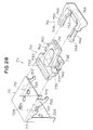
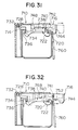
- FIG. 25 to 27 A different embodiment of the present invention will be described with reference to Figs. 25 to 27.
- This embodiment features an improved structure for mounting the blind apparatus to, for example, to a window sill.
- the whole structure of the blind apparatus will not be described since it may be substantially the same as that described before in connection with Figs. 1 to 6.
- a head box 612 has both longitudinal side edges 636 bent inward as at bends 637 so as to oppose each other. These bent edges 636 are retained by retainers 636 which projects outward from front and lower sides of the lower end of bracket 640, whereby the head box 612 is retained by the bracket 640.
- Fig. 25 illustrates a rotary drum 628 attached to the head box 612.
- a drum support 642 which fixes a rotary drum 628 to the head box 612, is disposed such that its lower surface contacts the bottom of the head box 612.
- the drum support 642 is connected at its upper end to a spacer 644 which has both side walls extended upward along both side walls of the head box 612.
- the upper end of the spacer 644 projects above the side edges 636 of the head box 612 and is configured in conformity with the bends 637 so as to fit in the latter.
- the portion of the spacer 644 fitting in the corresponding bend 637 has such a thickness that does not cause this portion to contact the retainer 638. According to this arrangement, it is possible that the bracket 640 catches and retain the side edges 636 of the head box 612 even at the portion where the spacer 644 is provided, through insertion of the retainer 638.
- Fig. 26 illustrates a stopper 632 secured to the head box 612.
- the stopper 632 is disposed at front lower part of the head box 612 in contact with both the front side wall and the front part of the bottom wall of the head box 612.
- the upper end of the portion of the side wall 632a behind the stopper 632 is connected to the connecting portion 648 which projects forwardly from a predetermined heightwise portion of the spacer 646, so as to be prevented from moving.
- the spacer 646 is disposed in a rear part of the head box 612 in contact with both the rear side wall and rear part of the bottom wall of the head box 612.
- the upper end of the spacer 646 is configured in conformity with the inner configuration of the bend 637 so as to fit in the latter.
- the portion of the spacer 646 fitting in the bend 637 has such a thickness that does not cause this portion to contact the retainer 638 of the bracket 640. According to this arrangement, the bracket 40 can retain the side edge 636 of the head box 612 even at the portion where the spacer 646 is provided, through insertion of its retainer 638.
- Fig. 27 illustrates a tilter 634 attached to the head box 612.
- the tilter 634 has the following components: a worm 648 attached to an end of the rotating operation rod 624 for rotation as a unit with the rod 624; a worm wheel 650 meshing with the worm 648 so as to be rotatingly driven by the latter; a warm wheel 652 meshing with the worm wheel 650 so as to be rotatingly driven by the worm 648; a tilter case 655 projecting from front side wall of the head box 612 to the lower face of the latter and capable of accommodating the worm 648, worm wheel 650 and the worm wheel 652; and a tilter cover 654 which conceals the portion of the tilter case 655 projecting from the front side of the head box 612.
- the worm wheel 652 is integrally carried by a rotor shaft 641 so as to rotate together with this shaft, thereby transmitting the rotation of this shaft to the rotary drum 628.
- the portion of the side wall 655a behind the tilter case 655 is connected to the connecting portion 658 which projects forward from a predetermined heightwise portion of the spacer 656 so as to be prevented from moving.
- the spacer 656 is disposed behind the head box 612 in contact with both the rear side wall and the rear part of the bottom surface of the head box 612.
- the upper end of the spacer 644 projects above the side edges 636 of the head box 612 and is configured in conformity with the bends 637 so as to fit in the latter.
- the portion of the spacer 644 fitting in the corresponding bend 637 has such a thickness that does not cause this portion to contact the retainer 638. According to this arrangement, it is possible that the bracket 640 catches and retain the side edges 636 of the head box 612 even at the portion where the spacer 644 is provided, through insertion of the retainer 638.
- the spacer for fixing the rotary drum, stopper and the tilter inside the head box is made to fit in the bent portions of both side edges of the head box so as not to interfere with the retainers of the bracket.
- the bracket therefore can retain the side edges of the head box even at portions where the drum, stopper and the tilter are disposed, by insertion of the retainers of the bracket.
- This enables a worker who attaches the bracket to, for example, a window sill to fix the bracket without paying specific attention to the position of the spacer. Consequently, restriction on the position of the bracket is eliminate to offer a higher efficiency of the work for installing the blind apparatus.
- a neat appearance is provided by virtue of the fact that both side edges of the head box are inwardly bent to oppose each other.
- FIG. 28 to 33 A different embodiment of the present invention will be described with reference to Figs. 28 to 33.
- This embodiment features an improved construction of a bracket for mounting the blind apparatus to, for example, to a window sill.
- the whole structure of the blind apparatus will not be described since it may be substantially the same as that described before in connection with Figs. 1 to 6.
- a bracket for installing the blind apparatus has a substantially L-shaped supporting frame 710 adapted to be fixed to, for example, a wall, a retainer member 714 which is held at the lower side of the horizontal portion 712 of the supporting frame 710 for movement to the left and right as viewed in Fig. 28, and an urging member 716 which is retained by the retainer member 714 for movement to the left and right as viewed in Fig. 28.
- the retainer member 714 has side walls 717 of a predetermined width dependent from both side edges of the horizontal portion 712 thereof.
- a retainer tab 722 having a recess 72 capable of retaining a front flange (one side end) of the head box 718 (see Fig. 29) is formed on the end of each side wall 717.
- Flat horizontal shelves 726 for slidably supporting the retainer member 714 are formed on the portions of the side walls 717 between the retainer tabs 722 and the base end of the horizontal potion 712 adjacent the vertical portion 724.
- the portions of the side walls 717 where the shelves 726 are formed are notched as at 727.
- a portion of the horizontal portion 712 adjacent the vertical portion 724 is cut in a U-shape and the cut portion is bent downward so as to serve as a spring retainer portion 728.
- a spring portion 732 is formed on one end of the retainer member 714.
- the spring portion 30 has an aperture 730 which receives and retains the spring retainer portion 728 of the supporting frame 710.
- a retainer projection 736 capable of supporting the rear flange (the other side end) of the head box 718 is formed on the lower side of the retainer member 714.
- a tapered surface 737 is formed under the retainer projection 736.
- a pair of guide grooves 738 along which the urging member 716 is guided and moved are formed on both lateral sides of the retainer member 714.
- the guide grooves 738 extend such that their one ends approach the sprig portion 732.
- a stopper 740 which projects in the heightwise direction of the retainer member 714 is formed near the other ends of the guide grooves 738.
- Resiliently deformable anchor tabs 742 are formed on the retainer member 714 at portions thereof adjacent the guide grooves 738, so as to be resiliently deflectable in the direction of breadth of the retainer member 714.
- Each anchor tab 742 has a substantially triangular connecting portion 743 having a bottom side projecting from one side of the anchor tab 742.
- the anchor tabs 742 come to face the notches 727 formed in the side walls of the supporting frame 710 so that they restore their original shapes to fit in the notches 727, so as to prevent the retainer member 714 from being withdrawn out of the supporting frame 710.
- a groove or recess 741 is formed in the lower face of the retainer member 714 at the end of the latter opposite to the spring portion 732.
- the urging member 716 has an operating portion 744 by means of which the urging member 716 is operable, and a pair of arms 746 projecting from both ends of the operating portion 744 perpendicularly thereto.
- Sliding shoe portions 748 formed on the ends of the arms 746 are adapted to be slidably received in the guide grooves 738 so as to be guided by these grooves.
- Urging tabs 746 are formed on the inner face of the arms 746 over the entire length of these arms 746, so as to oppose each other.
- Each urging tab 750 extending along the arm 746, has an intermediate inclined portion spaced apart a predetermined distance from the sliding shoe portion 748 so that the level of the urging tab 750 is lowered at a portion of the urging tab 750 remoter from the sliding shoe portion 748.
- a retaining projection 752 projects downward from the lower side of the lowered portion of the urging tab 750.
- the urging member 716 and the retainer member 714 are separately prepared.
- the sliding shoe portions 748 of the urging member 716 are inserted into the guide grooves 738 of the retainer member 714.
- the retainer member 714, together with the urging member 716 is moved into the gap between the horizontal portion 712 of the supporting frame 710 and the supporting shelves 726, such that the spring portion 732 is on the leading side as viewed in the direction of insertion.
- the anchor tabs 742 on the retaining member 714 are resiliently deflected inward by-being pressed by the side walls 717 of the supporting frame 710, thus allowing the retainer member 714 together with the urging member 716 to slide into the supporting frame 710.
- the anchor tabs 742 come to face the notches 727 so that they restore their original states to fit in the notches 727.
- the force exerted on the retainer member 714 rightward as viewed in Fig. 29 is dismissed, so that the retainer member 714 is allowed to move back to the original position, whereby the rear flange 734 of the head box 718 is retained by the upper face of the retaining projection 736. If the head box 718 has been deviated to the left or right from the right position, the head box position can be adjusted by moving the head box to the left or right. Then, the urging member 716 is pressed towards the vertical portion of the supporting frame 710, from the position shown by one-dot-and-dash line in Fig.
- a suitable tool 760 such as a screw driver is inserted into the gap between the lower face of the operating portion 744 of the urging member 716 and the head box 718.
- the tool 760 is then pulled rightward as viewed in Fig. 31.
- the retaining projection 752 of the urging member 716 slides over the front flange 720 of the head box 718 to the right side of he front flange 720 as indicated by one-dot-and-dash line in Fig. 31, whereby the front flange 720 is freed.
- the tool 760 is inserted into the recess 741 in the retainer member 714 and moved to the right as viewed in Fig. 32, so that the retainer member 714 is moved to the right as viewed in Fig. 31 to a position indicated by one-dot-and-dash line in Fig. 31.
- This causes also the retaining projection 736 to move to the position shown by one-dost-and-dash line, so that the retaining projection 736 no more supports the rear flange 734 of the head box 718 and allows the rear flange 734 to hall downward as viewed in the Figure.
- the front flange 720 of the head box 718 is pulled to the right as viewed in Fig. 32 while being held in such a manner as to float above the retaining portions 722, so that the front flange 720 clears the retaining portions 722 to allow the head box 718 to come off the bracket 711.
- the head box is temporarily held such that its one side edge is retained by the supporting frame while the other side edge is retained by the retaining member, and then the urging member is pressed into the supporting frame so as to fix the head box.
- This permits easy mounting and demounting of the head box to and from the bracket.
- the head box can be moved to the left and right while being supported by the head box and the retainer member, whereby lateral position adjustment of the head box can be done easily.
- FIG. 33 to 35 A different embodiment of the present invention will be described with reference to Figs. 33 to 35.
- This embodiment is suitable particularly when the blind apparatus has to be installed in a restricted space such a the space between two opposing sashes of a double-sash structure.
- the whole structure of the blind apparatus will not be described since it may be substantially the same as that described before in connection with Figs. 1 to 6.
- Fig. 33 shows a blind apparatus 801 installed in a restricted space between a sash 804 which is on the outer side of a room and a shoji (slidable wall consisting of wooden framework and a sheet of paper adhered to the frame work, used in Japanese-style houses), by means of a bracket 803.
- a sash 804 which is on the outer side of a room
- a shoji sliding wall consisting of wooden framework and a sheet of paper adhered to the frame work, used in Japanese-style houses
- Fig. 34 shows the bracket 803 in perspective view
- Fig. 35 illustrates, in plan, the bracket 803 to which the head box of the blind apparatus 801 is secured.
- the bracket 801 has a retainer member 808 having a pair of retaining portions 807 formed integrally thereof and adapted to engage with engaging flanges formed to project inward from upper end edges of a head box 802, and a supporting member 809 which support the retainer member 808 in such a manner as to allow the retainer member 808 to rotate within a horizontal plane between a head box engaging position where the above-mentioned retaining portions engage with the engaging flanges 806 of the head box 802 an a head box releasing position where the retaining portions 807 are disengaged from the engaging flanges 806, the supporting member 809 being adapted to be fixed in the aforementioned restricted space.
- the supporting member 809 is disposed between the sash 804 and the shoji 805 as shown in Fig. 23.
- the retainer member 808 has an operating lever 810 formed integrally therewith and rotatable manually relative to the supporting member 809 in a horizontal plane.
- the operating lever 810 is provided at its front end with a bent portion 811 which abuts a side surface of the head box 802 when the retainer member 808 is in the head box retaining position, and a release preventing portion 812 which is formed on the leading side of the operating lever as viewed in the direction of rotation for engagement, the release preventing portion 812 projecting by a height substantially equal to the height of projection of the bent portion.
- the release preventing portion 812 serves to prevent the operating lever from being rotated to the head box release position even when the front end of the operating lever is contacted by the sash or the shoji which is at the outer or inner side of the blind during opening or closing of the sash or the shoji.
- Numeral 813 designates a stopper which serves to stop the operating lever 810 at the head box stop position.
- the bracket 803 has the operating lever, the bent portion formed by downwardly bending the front ed portion of the operating lever, and release preventing portion which is formed at the leading side of the bent portion as viewed in the direction of rotation of the operating lever for engagement, by a height substantially the same as the height of projection of the bent portion.
- the state of the bracket can be switched between a state in which it retains the head box and a state in which it releases the head box, by a mere rotation of the operating lever.
- the amount of projection of the operating lever is minimum, i.e., the width of the bracket as measured in the direction perpendicular to the head box is reduced to the minimum value.
- the front end of the operating lever, projecting beyond the front side of the head box is bent downward, and the release preventing portion is formed to extend within a horizontal plane so as to incline towards the inner side of the head box, at the leading side of the downward bend as viewed in the direction in which the operating lever is rotated to disengage the head box.
- the release preventing portion serves to prevent undesirable release of the head box from the bracket which otherwise may be caused due to jolt of the sash or shoji, thereby preventing accidental drop of the head box.
- FIG. 36 to 38 A different embodiment of the present invention will be described with reference to Fig. 36 to 38.
- This embodiment employs a reduced number of operating members such as cords so as to provide a neat appearance of the blind apparatus.
- the whole structure of the blind apparatus will not be described since it may be substantially the same as that described before in connection with Figs. 1 to 6.
- a lifting cord 905 extends downward from a head box 901 through holes formed in slats so as to be connected at its lower end to a bottom rail 904.
- the cord 905 is turned 90° around a turning roller (not shown) in the head box 901 and extends along the head box 901 and emerges from the head box 901 at a portion of the latter near one longitudinal end of the head box 901.
- the cord 905 is then extended downward through a hollow of a tilt operation lever 906.
- a clip 907 is connected to the other end of the cord 905.
- Figs. 36 and 37 are sectional views showing the portion of this embodiment around the end of the head box 901 from which the cord 905 is extracted.
- a tilt rotation shaft 908 is rotatably journaled in the head box 901 so as to extend in the longitudinal direction of the head box 901 and so as to be able to tilt the ladder cord 903 in a manner known per se for the purpose of adjusting the light coming through the gaps between slats.
- Numeral 909 indicates a case which is fixed to the head box 901, while 910 indicates a gear which is fixed to the tilt rotation shaft 908.
- the ladder cord 903 is connected at its one end to the tilt rotation shaft 908.
- Numeral 911 designates a rotary shaft having a hollow cylindrical portion and mounted in a lower portion of the case 909.
- a bevel gear 912 journaled inside the head box engages with an intermediate gear 913 which is rotatably supported in the bracket.
- the intermediate gear 913 is internally toothed to engage with the gear 910 fixed to the tilt rotation shaft 908. Due to the presence of the intermediate gear, the axes of the rotary shaft 911 and the tilt rotation shaft 908 are twisted with respect to each other.
- the outer end of the rotary shaft 901 projecting outward from the head box is coupled to a hollow cylindrical tilt operating rod 915 through a universal joint 914.
- Numeral 916 designates a turning roll which is rotatably supported in the case 909 such that the axis of this roll is on the extension of the axis of the above-mentioned rotary shaft 911.
- the turning roll 916 serves to turn the lifting cord 905 extending through the head box such that the cord 905 is threaded through the hollows of the bevel gear 912, rotary shaft 911 and the tilt operation rod 915.
- the turning roll 916 is spaced as much as possible from the universal joint 914 so as to prevent entanglement of the cord 905 at both sides of the roll 916. More specifically, the turning roll 916 is disposed at an upper part of the head box, such that the axis of the turning roll 916 is inclined both to the extension of the head box 901 and the axis of the bevel gear 912.
- the illustrated embodiment may employ a stationary roller and a movable knurled roller which are disposed at predetermined positions in the head box 901 so as to nip the lifting cord 905 therebetween.
- the knurled roller may be movable between a position where it restrains the lifting cord 905 from moving and a position where it permits the lifting cord 905 to move freely.
- a switching mechanism may be provided to forcibly switch the knurled roller between these two positions.
- Such a switching mechanism may be operated by means of an operation cord 918 which together with the lifting cord 905 turns around the roll 916 and extracted to the exterior through the tilt operation rod 915.
- a knob 917 connected to the lower end of the tilt operation rod 915 as illustrated in Fig.
- the knob 917 is mounted in such a manner as to be movable up and down relative to the tit operation rod 915 so that it dismisses the movement of the lifting cord when it is pulled downward.
- the turning roll 916 for guiding the lifting cords 905 into the bevel gear 912 and the hollow of the tilt operation rod 915 is disposed at an upper portion of the space inside the head box, at a position which is substantially on the extension of the bevel gear 912 and at level above that of the tilt rotary shaft 908. Therefore, lifting cords can have sufficient margin at their portions on both sides of the turning roll 916, so that entanglement tendency of the cords is suppressed to ensure smooth movement of the cords.
- the cord 918 for operating such a stopping device can be extended together with the lifting cords 905 via the turning roll 916 and through the hollow of the tilt operation rod 915. Entanglement of the cords also is suppressed in this case, thus improving operability of these cords.
- the problem of enlargement of the tilt operation rod which hitherto has been encountered with conventional apparatus, can be eliminated.
- Fig. 38 shows a modification of the embodiment shown in Figs. 36 and 37.
- This modification has a construction substantially the same as that of the embodiment of Figs. 36 and 37 except for the constructions of the bracket, rotary shaft, bevel gar and the intermediate gear.
- the gear fixed to the rotary shaft 911' is an axially elongated worm gear 912', and an intermediate gear 913' as a drum is held in engagement with this worm gear 912'.
- a cord turning member such as the turning roll for guiding the lifting cords into the hollow of the gear and then into the hollow of the tilt operation rod is disposed at an upper portion of the space inside the head box substantially on the extension of the hollow of the gear and at a level above the tilt rotary shaft, so as to avoid any interference between the lifting cords and the tilt rotation shaft, thus eliminating entanglement of plural lifting cords to ensure smooth movement of the lifting cords.
- a stopping device for stopping the lifting cords is disposed in the head box.
- a cord for operating this stopping device may be extended together with the lifting cords via the turning roll and through he tilt operating rod, with reduced risk of the cords, thus improving reliability of operation.
- the gear on the tilt operation rod is designed in the form of a long worm gear, the width of he head box can be reduced advantageously.
Abstract
Description
- The present invention relates to a blind apparatus which is suspended on a wall or the like of a room and which can be hoisted up or down arbitrarily. More particularly, the present invention relates to a horizontal type blind in which a plurality of slats are supported horizontally by means of a ladder cord hung from a head box at a distance between respective upper and lower slats and in which lifting cords fit to a bottom rail disposed at the bottommost of the slats are introduced upward through the slats and then introduced into the head box, the lifting cords being further introduced within the head box horizontally toward one end of the head box, and in which the slats are lifted up or down by pulling or loosening the lifting cords and turned by moving up or down vertical cords located before and after the aforementioned ladder cord.
- Horizontal type blind apparatuses of the aforementioned type have been widely used. The horizontal type blinds enable the user to lift up or down the slats and adjust the slat angle easily. It is also possible to suspend the slats at a desired height by fastening the lifting cords at a desired position by means of a stopper device.
- Recently, a new type blind apparatus has been proposed. According to the proposed invention, a rotating operation rod for rotating the slats is disposed near one end of the head box, and one end of the lifting cord is passed through the rotating operation rod and introduced downward from the bottom thereof. The slats are rotated by means of the rotating operation rod and lifted up or down by means of the lifting cords.
- An example of the invention has been disclosed in Japanese Utility Model Laid-Open No. 61-102797.
- In the horizontal type blind apparatus of this type, a stopper device which holds the motion of the lifting cords is incorporated near one end of the head box in order to fasten the lifting cords at a desired position.
- In the prior art, the following stopper devices for the blind apparatus have been proposed. According to Japanese Patent Laid-Open No. 58-27399, lifting cords which are capable of lifting up or down the slats are inserted through a hollow operation rod which is capable of changing the inclination angle of the slats, and a grip disposed at the lower end of the operation rod is provided with a locking metal piece which is capable of locking the lifting up or down of the lifting cords.
- However, the conventional stopper devices for such blind apparatus have the following problems. That is, because the locking metal piece is provided on the grip, an operating load is applied to the operation rod when the slats are lifted up or down. Thus, it is necessary to provide an operation rod having a large diameter in order to obtain sufficient strength, thus the size of the operation unit increases.
- To solve the aforementioned problem, according to Japanese Utility Model Laid-Open No. 3-35035, in a differential drum which is capable of transmitting the rotation of the operating handle disposed in the head box to a rotation shaft, a stopper device is incorporated which has a conical portion having a U-shaped cross section capable of holding the lifting up or down of by nipping the lifting cords in cooperation with the tapered portion of the differential drum, and the lifting cords introduced from the head box are inserted through the hollow operating handle and then led out of the bottom of the operating handle. Additionally, one end of a stopper releasing cord which is capable of releasing the fastening of the lifting cords is connected to the stopper. Regarding the connection of the stopper releasing cord to the stopper, one end of the stopper releasing cord is introduced from the bottom of the stopper into the conical portion and a knot is formed in order to contain the knot of the stopper releasing cord within the conical portion. The other end of the stopper releasing cord is inserted through the operating handle and introduced out from the bottom end of the operating handle. When it is desirable to lift up the slats, the lifting cords are pulled downward to release the stopper. When it is desirable to let down the slats, the stopper is released by pulling the stopper releasing cord downward.
- However, because the differential drum includes the function for transmitting the rotation of the operating handle to the rotation shaft as well as a stopper, the internal space of the differential drum is increased and the size of the differential drum is increased. Thus, the play of the lifting cord is increased. Additionally, because the differential drum and the stopper rotate integrally or relatively to each other, the lifting cords are likely to be twined. Further, because the stopper cannot be assembled beforehand because of the construction reasons, the workability of the assembly is low.
- Still further, because the knot formed in the stopper releasing cord is contained in the conical portion of the stopper, the diameter of the conical portion must be increased. Thus, the conical portion must be formed so as to have a U-shaped cross section. Thus, when the lifting cords are nipped between the stopper and the tapered portion, the lifting cords slip so that the cord cannot be nipped firmly. That is, there is a possibility that the stopper may not be activated. The aforementioned problem is the first problem of the blind apparatus of the prior art.
- As a conventional blind apparatus for operating the blind apparatus of the aforementioned type, the following invention has been proposed. For example, according to Japanese Utility Model Laid-Open No. 3-35035, a stopper device which is capable of locking the lifting up or down of the lifting cords is provided within the head box. The lifting cords are inserted through the operation handle and connected to different positions of the lifting operation knob which is rotatable with the operation handle, so that the slats can be lifted up or down. The bottom end of the releasing cord which is capable of operating the stopper mechanism is inserted through the operation handle and connected to the releasing operation knob which is rotatable with the operation handle, so that the slats can be lifted up or down. When the releasing operation knob is pulled down, the stopper mechanism is released, so that the slats descend.
- However, the aforementioned conventional blind apparatus has the following problems. That is, when the slats are rotated, if the operation handle is turned, the lifting operation knob and the releasing operation knob rotate integrally therewith. Thus, the lifting cords and the releasing cord are twined within the operation handle.
- Japanese Utility Model Laid-Open No. 57-99094 has disclosed an example in which the lifting cords are prevented from being twined. Namely, the bottom ends of the lifting cords which droop from the stopper mechanism provided at the bottom of the rotating operation rod are inserted through respective insertion holes provided on the knob having the same number of insertion holes as the number of the lifting cords and then connected with each other. However, this system prevents the lifting cords introduced from the bottom end of the rotating operation rod from being twined, because the stopper mechanism is provided at the bottom end of the rotating operation rod. Thus, even if this system is utilized in an apparatus which includes a stopper mechanism within the head box, it is not possible to prevent the lifting cords from being twined within-the operation handle. The aforementioned matter is the second problem of the conventional blind apparatus.
- As another example of conventional blind apparatus, the following apparatus is available. For example, according to Japanese Patent Laid-Open No. 60-113823, a universal joint is utilized. In this construction, bifurcated pieces are provided on each end of a hollow driving shaft and a hollow driven shaft and both bifurcated pieces are pivotally connected by a hollow connecting piece. Both bifurcated pieces and the connecting piece are pivotally connected by fitting a protrusion of each connecting point of the connecting piece into a receiving hole formed at each connecting point of each bifurcated piece. Both bifurcated pieces and the connecting piece are pivotally connected so that the center lines of the aforementioned shafts and a line connecting the respective connecting points of the connecting piece and the bifurcated pieces pass through the center of the connecting piece.
- However, the aforementioned conventional blind apparatus has the following problem. That is, because the driving shaft, the driven shaft, the bifurcated piece and the connecting piece are hollow, the bifurcated pieces are bent by a downward load applied to the operation rod, so that the protrusions of the connecting piece are disengaged from the receiving holes of the bifurcated pieces.
- According to another example of conventional apparatus, a washer is attached to the tip of the protrusion of the connecting piece in order to prevent the protrusions of the connecting pieces from being disengaged from the receiving holes of the bifurcated pieces. However, because a washer must be attached to every protrusion, the work necessary for this treatment is very troublesome.
- These points are the third problem of the conventional blind apparatus.
- In the aforementioned known blind apparatus, the device which inclines all the slats all at once to adjust the light shielding is called a tilter.
- The tilter of the conventional blind apparatus contains, for example, a worm gear for transmitting the rotation of the rotating operation rod to a transmission shaft and a worm wheel and some types of the apparatus contain the tilter which is provided within the head box located at the top end of the rotating operation rod. The lifting cord is inserted through the rotating operation rod.
- However, the tilter of the conventional blind apparatus has the following problem. Namely, when the slats are rotated by rotating the rotating operation rod, if the slats are lifted halfway and the rotating operation rod with the lifting cord introduced from the bottom of the rotating operation rod being hung on a cord hanger is rotated, the lifting cord within the rotating operation rod is twined. For this reason, a repellant force which tries to untwine the lifting cord is caused so that the rotating shaft rotates. Thus, it is not possible to maintain the slats in a desired condition.
- The smaller the gear ratio between the worm gear and the worm wheel is, the more excellent rotation transmission efficiency the tilter has. However, the tilter utilizes braking force which occurs between the worm gear and the worm wheel in order to prevent the rotation shaft from being forced to rotate due to the aforementioned repellant force and an external force applied to the slat. Thus, the actual gear ratio is set to a relatively high value. For this reason, it is necessary to rotate the rotating operation rod by five - six turns in order to tilt the slats by 180 degrees.
- Although the aforementioned problem can be solved-if the worm gear and the worm wheel are made of material which is difficult to slip, if they are made of such material, it is not possible to secure a smooth rotation when the rotating operation rod is rotated, so that the gear ratio increases. This is the fourth problem of the conventional blind apparatus.
- As the rotating operation rod of the conventional blind apparatus, the following apparatus has been proposed. For example, according to Japanese Utility Model Laid-Open No. 56-70091, a safety device having a substantially T-shaped cross section, which has a disk shaped head at one end of the thread portion is fixed to the rotating operation rod and the grip and the lifting cords are wound around the safety devices.
- According to Japanese Patent Laid-Open No. 61-56383, T-shaped hooks protrude at two positions which are located at a predetermined distance along the length of the rotating operation rod and the lifting cords are wound around the hooks.
- However, the rotation operation bar of the conventional blind apparatus has the following problem. That is, in the apparatuses disclosed in Japanese Utility Model Laid-Open No. 56-70091 and Japanese Patent Laid-Open No. 61-56383, the lifting cords are only wound around the hook having a substantially T-shaped cross section, which protrudes sideways from the rotating operation rod or the grip. Thus, when the slats are blown by the wind or the rotating operation rod is rotated with the condition in which the blind apparatus is descended halfway and the lifting cord is wound around the hook, the lifting cord is unwound from the hook.
- Generally, a pair of lifting cords are disposed near both ends of the blind apparatus. However, it is necessary to provide a large size blind apparatus with a further or more lifting cords which are located in the center of or near the center thereof.
- In a blind apparatus which utilizes at least three or more lifting cords, as compared with lifting cords which pass near both ends of the slats, a larger load is applied to lifting cords which pass in the center of the slats by a bottom rail and slats.
- Because the lifting cord stopper device which fastens the lifting cords to stop the blind fastens all the lifting cords with equal force, the lifting cords which are applied with the largest load and which pass in the center of the slats are likely to slip even when the stopper fastens the lifting cords, so that the lifting cord stopper device cannot fasten the lifting cords which pass near the center of the slats. As a result, when the slats are descended halfway, the center portions of the slats and the bottom rail droop so that the level condition of the slats and the bottom rail cannot be maintained.
- This point is also one of the problems which must be solved about the blind apparatus.
- The blind apparatuses of the aforementioned types are fixed to a wall or the like of a room through a bracket.
- As a construction which utilizes such fixing, the following types are known.
- In the head box of conventional blind apparatus, the respective edges of both sides are bent inward and the head box is mounted on brackets by hooking the edges of both sides on hooking pieces of the brackets. The head box contains a rotating drum to which one end of the ladder cord supporting the slats is connected so that the ladder cord can be wound or rewound, a tilter which transmits the rotation of the rotating operation rod to the rotating drum and mechanical parts such as a stopper capable of holding the motion of the lifting cords for lifting up or down the slats. When the respective components are fixed to the head box, the top portions thereof are in contact with the aforementioned edges of the head box.
- However, the aforementioned conventional blind apparatuses have the following problem. Because the mechanical parts are in contact with some locations of the edge portions of the head box, the brackets must be mounted at positions which no mechanical parts are fit to. Thus, when brackets are mounted on a window frame or the like, it is necessary to set the mounting positions of the brackets so as to avoid an interference between the mechanical parts and the brackets.
- Although, in a blind apparatus in which both edge portions of the head box are bent outward, the brackets can be attached freely to any positions of the head box without taking into account the positions of the mechanical parts, the edge portions of the head box protrude outward, so that the width of the bracket must be increased. Thus, the appearance of the head box is deteriorated. This is also one of the problems which must be solved in conventional blind apparatuses.
- Still another type of conventional blind bracket is disclosed in Japanese Utility Model No. 60-22237. The blind bracket disclosed therein comprises a substantially L-shaped supporting frame fit to a window frame and an engaging member detachable from the supporting frame. In the supporting frame, a cut-out dented portion is formed at the bottom of the beginning end of its level portion and a upward facing dented portion is formed at the front end of the level portion. The engaging member is supported by a supporting frame so that the engaging member is movable back and forth. In the engaging member, an engaging protrusion is formed at a position which corresponds to the cut-out dented portion when the engaging member is inserted into the supporting frame completely, and a locking piece and a locking tongue are formed at a position which corresponds to the engaging dented portion.
- When the engaging member is inserted into the supporting frame completely, the top edge of one side of the box (otherwise called head box) is nipped between the cut-out dented portion and the engaging protrusion and fixed. The top edge of the other side is nipped between the locking tongue and the locking piece, the locking tongue and the locking piece sliding beyond the top edge thereof, in order to hold the right/left movement of the head box. Additionally, the top edge of the other side is nipped between the locking tongue and the engaging dented portion in order to restrict the up/down motion of the head box, thereby fixing the head box to the brackets. By pulling the engaging member from the supporting frame by a predetermined distance, the engaging protrusion which supports the bottom of the top edge of one side of the head box is moved so that the top edge is released from being supported. The locking tongue goes beyond the top edge of the other side, so that seizing of the top edge in the right/left direction and in the upward direction is eliminated. Thus, the head box can be removed from the bracket.
- However, as for the aforementioned conventional bracket for the blind apparatus, if the engaging member is pulled out from the supporting frame, the top edge of one side of the head box becomes unsupported, so that the head box drops from the brackets. Thus, to adjust the right/left position of the blind apparatus after the head box is mounted to the supporting frame, it is necessary to support the head box by hand or the like to stop the head box from dropping. For this reason, according to this invention, it is not possible to adjust the right/left position of the blind apparatus easily.
- Depending on a case, it is requested to mount the blind apparatus of the aforementioned type in a narrow space, for example, between double sashes or between a sash and a Japanese sliding paper door. In such a case, because the distance between the inside and outside sashes is small, it is desirable to reduce the back-and-forth dimension of the head box and further it is desirable that the bracket does not protrude.
- The bracket which can meet such a demand comprises a supporting member mounted on the top surface of the top mounting space and a locking member mounted horizontally rotatably with respect to the supporting member. A locking portion which is locked on a locking protruded edge formed inside of the top edge of the groove type head box is formed on the locking member. By rotating the locking member by means of an operation lever formed integrally with the locking member, the head box is locked or released.
- Japanese Patent Laid-Open no. 40-34054 has disclosed the following type of the device for fixing a blind apparatus or a curtain supporting frame. This device comprises a supporting frame in which protruding edges which direct inward are formed at the top ends on both side walls and a groove is formed between the protruding edges and a fixing device in which a circular rise-up entering the groove of the supporting frame is formed on both sides of a substrate, in which a protruding edge engaging with the bottom faces of both protruding edges of the supporting frame is formed on the ends, in which handles are provided in succession between both protruding edges and in which a nail hole is formed in the center thereof. The fixing device is nailed on the upper beam of a partition of a room, window or the like so that the device is freely rotatable. The bent pieces of the supporting frame are hooked on both protruding edges.
- Japanese Patent Laid-Open no. 63-106893 has disclosed a blind apparatus fixing metal piece in which engaging edges are formed by bending inward the top edges of the groove type frame and the engaging edges of the frame are engaged therewith by rotating the lever to fix the frame, the fixing metal piece being constructed so that the engaging member which is engaged between the bottom of the frame and the engaging edge is supported so as to be rotatable and that a lever for rotating the engaging member is connected to the engaging member.
- Further, Japanese Patent Laid-Open No. 63-173497 has disclosed a blind fixing metal piece in which engaging edges are formed by bending inward the top edges of a groove type frame and the engaging edges of the frame are engaged therewith by rotating the operation lever, the fixing metal piece being constructed so that a shaft from which the operation lever originates is supported on one end of the supporting member so as to be rotatable, the supporting member being provided with a locking portion for supporting one engaging edge of the frame, one side of the shaft being provided with a locking groove which is locked on the other engaging edge according to the rotation of the operation lever.
- However, if a blind apparatus is mounted in a narrow space, for example, between a sash outside and a Japanese sliding paper door inside by means of the aforementioned bracket, the protrusion dimension of the front end of the operation lever is so large that a force for releasing engagement between the bracket and the head box is applied to the front end of the operation lever. For example, if a sliding paper door is opened, the operation lever is turned in the direction in which the head box is released, so that the blind may drop. This is also one of the problems which must be solved about conventional blind apparatus.
- It is therefore a primary object of the present invention to provide an improved blind apparatus which can at least alleviate the above-described problems of the known blind apparatuses.
- More specifically, an object of the present invention is to provide a blind apparatus having an improved stopper device.
- To this end, according to one aspect of the present invention, there is provided a blind apparatus comprising: a head box; a bracket having retaining portions for retaining both longitudinal side edges of the head box so as to enable mounting of the head box; a series of vertically spaced slats arranged substantially in parallel with one another and supported by ladder cords; a bottom rail under the series of slats; a rotary drum disposed inside the head box, each the ladder cords being connected to the rotary drum so as to be wound and rewound on and from the drum; a tilter input shaft extended downward from one end of the head box and rotatable to cause tilting of the slats; a tilter disposed in the head box, for transmitting the rotation of the tilter input shaft to the rotary drum; a hollow rotating operation rod coupled to the tilter input shaft through a universal joint; a hollow grip provided at the lower end of the rotating operation rod; lifting cords connected at their one ends to a bottom rail and extended through holes formed in the series of slats into the head box and then extended through the interior of the rotating operation rod and the grip and then through the grip so as to emerge from the lower end of the grip; a stopper device disposed in the head box and capable of restraining the lifting cords from moving; a stopper releasing cord connected at its one end to the stopper and extended through the interior of the rotating operation rod and the grip; wherein the stopper device includes a stopper case fixed to the head box and opened at its upper end; a cord nozzle provided on one end of sad stopper case so as not be able to move in the longitudinal direction; a cord stopper provided on the stopper case in such a manner as to be able to move in the longitudinal direction relative to the stopper case but not to be able to rotate relative to the stopper case; and an urging spring for normally urging the code stopper towards the cord nozzle; wherein the cord stopper has: a bottom portion fitted to the stopper case and having a bore in which the lifting cords are extended; a conical end projected from the bottom portion and cooperating with the code nozzle in clamping therebetween the lifting cords so as to fix the lifting cords; the cord stopper further having a first insertion hole extending from the bottom portion to open in the outer peripheral surface portion near of the cord stopper near the end of the cord stopper, and second insertion hole provided at the radially outer side of the first insertion hole and penetrating the bottom portion, the stopper release cord being extended through the first insertion hole from the bottom portion to emerge from the outer peripheral surface portion and then extended through the second insertion hole so a to emerge from the bottom portion opposite to the end of the cord stopper so as to be fastened to the cord stopper.
- Another object of the present invention is to provide a blind apparatus having an improved operating arrangement capable of preventing twining of lifting cords.
- To this end, according to another aspect of the present invention, there is provided a blind apparatus wherein the grip is rotatable integrally with the rotating operation rod and movable up and down relative to the rotating operation rod by a predetermined amount, the grip having a bore through which the lifting cords are extended for movement up and down, a twining preventive ring being attached to the grip for vertical movement integrally with id grip and for rotation relative to the grip, whereby the stopper can be released by mans the stopper release cord as a result of rotation and relative movement of the grip.
- Still another object of the present invention is to provide a blind apparatus having an improved operating arrangement which eliminates undesirable disengagement of the components and which can easily be assembled.
- To this end, according to still another aspect of the present invention, there is provided a blind apparatus, wherein the universal joint includes: a first bifurcated piece having a pair of branches projecting axially from one end of the tilter input shaft so as to oppose to each other, each the branch having a first pin receiving hole; a second bifurcated piece having a pair of branches projecting axially from one end of the tilter input shaft so as to oppose to each other, each the branch having a second pin receiving hole; and a hollow interconnecting piece having connecting pins rotatably received in the first and second pin receiving holes so as to interconnect the tilter input shaft and the rotating operation rod such that the tilter input shaft and aid rotating operation rod are rotated as a unit with each other while changing the angle formed therebetween; wherein the connecting pins interconnecting aid tilter input shaft and the interconnecting piece are provided on their heads with protruding portions which protrude in the direction of axis of the interconnecting piece, the first pin-receiving holes in the tilter input shaft is conically shaped such that its radius progressively increase towards the outer side.
- A further object of the present invention is to provide a blind apparatus having an improved tilter.
- To this end, according to a further aspect of the present invention, there is provided a blind apparatus wherein the tilter has a torque adding device which poses additional rotational torque such that a grater torque is required for causing the tilter shaft to start to rotate than that required after the tilter shaft has been started to rotate.
- A still further object of the present invention is to provide a blind apparatus having an improved rotating operation rod or a grip.
- To this end, according to a still further aspect of the present invention, there is provided a blind apparatus wherein the rotating operating rod comprises a pair of hooks spaced from each other in the axial direction, each of the hooks being capable of holding a lifting cord wound thereon, each the hook including: a connecting portion which can be attached to aid rotating operation rod and a T-shaped protruding portion having two wing portions projecting laterally from the connecting portion; one of the two wing portions of the T-shaped protruding portion and the connecting portion form therebetween a groove-like clamping portion, the hooks being arranged such that their clamping portions oppose each other.
- A yet further object of the present invention is to provide a blind apparatus employing three or more lifting cords, improved to prevent drooping of the slats at the mid portion of the blind apparatus so as to maintain all the slats correctly in horizontal posture.
- To this end, according to a yet further aspect of the present invention, there is provided a blind apparatus, wherein at least three lifting cords are used, characterized in that the central lifting cord, after being introduced into the head box, turns around a guide roller to extend away from the stopper device and then turned around a turning roller so as to be introduced into the stopper device.
- A yet further object of the present invention is to provide a blind apparatus having an improved mounting structure.
- To this end, according to a yet further aspect of the present invention, there is provided a blind apparatus, wherein the upper end edges of side walls of the head box are bent inward to oppose each other so as to form a mounting surface, and the rotary drum and the stopper device are fixed in the head box by means of spacers such that the levels of the rotary drum and the stopper device are below the level of the lower end of the retaining portions of the bracket, the spacers being shaped in conformity with the configurations of the bent upper edges of the head box so that their upper ends may not contact with the retaining portions of the bracket.
- A yet further object of the present invention is to provide a blind apparatus having an improved mounting bracket.
- To this end, according to a yet further Aspect of the present invention, there is provided a blind apparatus, wherein the bracket comprises a supporting frame, a retainer member and an urging member, the supporting frame having a vertical portion by means of which the supporting frame is secured to a wall or the like and a horizontal portion which is connected to the vertical portion orthogonally thereto, the retaining portion including a retaining tab formed on the horizontal portion of the supporting frame and capable of retaining one side of the head box, and a retaining projection formed on the retainer member so as to retain the other side of the head box; the horizontal portion including retaining portions formed on the free end thereof, and supporting shelves for supporting the retainer member such that the retainer member is movable into and out of the supporting frame, the retainer member including a spring portion for normally urging the retainer member into the supporting frame, a retaining projection formed on the lower face of the retainer member, guide grooves for guiding the urging member when the urging member is moved into and out of the supporting frame, a retaining portion provided on ends of the guide grooves so as to restrict the movement of the urging member, and anchor tabs for restricting movement of the retainer member out of the supporting frame; the urging member including an operating portion operable to cause movement of the urging member, a sliding portions received in the guide grooves so as to slide along the guide grooves, a resiliently deflectable urging tab connected between the operating portion and the sliding part, and a retaining projection formed on a lower portion of the urging member and capable of being fitted in a space between the retaining portions of the supporting frame and the one side of the head box.
- A yet further object of the present invention is to provide a blind apparatus which is suitable for mounting in a restricted space such as, for example, a space between two sashes of a double-sash arrangement.
- To this end, according to a yet further aspect of the present invention, there is provided a blind apparatus wherein the bracket comprises: a rotary member having retaining portions on both lateral sides thereof; and a supporting member for rotatably supporting the rotary member such that the rotary member is rotatable within a horizontal plane between a retaining position where the retaining portions of the rotary member retain both side edges of aid head box and a release position where the retaining portions of the rotary member release the side edges of the head box, the supporting member being capable of being fixed in a restricted space between a pair of shield members which are movable between and open positions, the rotary member including an operating lever formed integrally therewith, for causing rotation of the rotary member within a horizontal plane relative to the supporting member, the operating lever being provided at its front end with a bent portion which abuts a side wall of the head box when the rotary member is in the head box retaining position and a release prevention portion which projects by an amount substantially the same as the amount of projection of the bent portion, at the leading side of the bent portion as viewed in the direction of rotation of the operating lever towards the head box retaining position, whereby undesirable rotation of the operation lever to the head box release position, due to eventual contact of the operating lever with one of the shield members during opening or closing of the shield member.
- These and other objects, features and advantages of the present invention will become clear from the following description of a number of embodiments in accordance with the invention.
-
- Fig. 1 is a drawing showing the blind apparatus which is an embodiment of the present invention;
- Fig. 2 is a disassembly perspective view of the stopper device;
- Fig. 3 is a perspective view of the stopper device;
- Fig. 4 is a sectional view taken along the lines 4-4;
- Fig. 5 is a drawing showing a stopper device in which a lifting cord is fastened;
- Fig. 6 is a drawing showing a stopper device in which fastening of the lifting cord is released;
- Fig. 7 is an exploded perspective view of a grip and parts therearound in a different embodiment;
- Fig. 8 is a sectional view of the grip shown in Fig. 7;
- Fig. 9 is a sectional view taken along the line IX-IX of Fig. 8;
- Fig. 10 is an exploded perspective view of a universal joint used in a different embodiment;
- Fig. 11 is an exploded perspective view of a tilter used in a different embodiment;
- Fig. 12 is an illustration of the tilter of Fig. 11 attached to a head box;
- Fig. 13 is a sectional view taken along the line XIII-XIII of Fig. 12;
- Fig. 14 is an illustration of a torque adding device in a state in which tilter shaft has been rotated;
- Fig. 15 is a diagram showing the manner in which the driving torque is changed in relation to time;
- Fig. 16 is an illustration of a different form of the torque adding device;
- Fig. 17 is an illustration of a still different form of the torque adding device;
- Fig. 18 is a schematic illustration of a blind apparatus as a different embodiment of the present invention;
- Fig. 19 is an illustration of hooks on which lifting cords are wound, in the embodiment shown in Fig. 18;
- Fig. 20 is an illustration of the manner in which the ends of lifting cords are treated;
- Fig. 21 is a partly-sectioned front elevational view of a different embodiment of the blind apparatus of the present invention;
- Fig. 22 is a partly-sectioned plan view of the blind apparatus shown in Fig. 21;
- Fig. 23 is an enlarged view of a critical portion of the blind apparatus shown in Fig. 21;
- Fig. 24 is an illustration of a manner in which lifting cords are guided in the blind apparatus shown in Fig. 21;
- Fig. 25 is an illustration of a critical portion of a different embodiment of the blind apparatus of the present invention, illustrative of a rotary drum mounted in the head box;
- Fig. 26 is an illustration of a stopper mounted in the head box in the embodiment shown in Fig. 25;
- Fig. 27 is an illustration of a tilter attached to the head box in the embodiment shown in Fig. 25;
- Fig. 28 is an exploded perspective view of a different embodiment of the blind apparatus in accordance with the present invention;
- Fig. 29 is an illustration of a critical portion of the embodiment shown in Fig. 28, explanatory of the manner in which the head box is retained at its one side by a supporting frame;
- Fig. 30 is an illustration of a critical portion of the embodiment shown in Fig. 28, illustrative of the head box attached to a bracket;
- Fig. 31 is an illustration of a critical portion of the embodiment shown in Fig. 28, illustrative of a state in which an urging member has been pulled outward of the supporting frame to enable a head box from the bracket;
- Fig. 32 is an illustration of a critical portion of the embodiment shown in Fig. 28, illustrative of a state in which a retainer member has been pulled outward of the supporting frame to enable the head box from the bracket;
- Fig. 33 is an illustration of a different embodiment of the blind apparatus in accordance with the present invention, secured by a bracket having a specific structure;
- Fig. 34 is a perspective view of the bracket used in the embodiment shown in Fig. 33;
- Fig. 35 is a plan view of the head box in the embodiment shown in Fig. 33, fixed by the bracket shown in Fig. 34;
- Fig. 36 is a sectional view of a tilt mechanism in a different embodiment of the blind apparatus in accordance with the present invention;
- Fig. 37 is a sectional view taken along the line A-A of Fig. 36; and
- Fig. 38 is a sectional view of a modification of the tilt mechanism shown in Fig. 36.
- Fig. 1 shows an embodiment of the blind apparatus of the present invention. In this blind apparatus, a plurality of
slats 10 are arranged vertically at a predetermined distance. Ahead box 12 is disposed at the top end of ten rows of these slats and abottom rail 14 is disposed at the bottom end. Aladder cord 16 is provided between thehead box 12 and thebottom rail 14 to support therespective slats 10. The top end of theladder cord 16 is connected to arotating drum 17 which is rotatably provided within thehead box 12 so that the ladder cord can be wound or released. The inclination angle of theslat 10 can be changed by the rotation of therotating drum 17. A hollowtilter input shaft 22 is introduced from one end of thehead box 12 and a hollowrotating operation rod 24 having ahollow grip 32 which is disposed at the bottom end thereof is rotatably connected to the bottom end of thetilter input shaft 22. The rotation of therotating operation rod 24 is transmitted to atilter 20 provided near one end of thehead box 12 through thetilter input shaft 22. The rotation received by thetilter 20 rotates therotating drum 17 which is connected to therotating shaft 23 through the rotatingshaft 23. One ends of thelifting cords 18 are connected to thebottom rail 14 and the other ends thereof are introduced into thehead box 12 through insertion holes (not shown) which are provided onslats 10. The other-ends thereof are passed through astopper device 21 provided near one end of thehead box 12, introduced through thetilter input shaft 22, therotating operation rod 24 and thegrip 32, and then are connected to theknob 26 which is disposed on the bottom of thegrip 32 so that thelifting cords 18 can ascend or descend. As described later, thestopper device 21 is capable of holding the motion of thelifting cords 18. One end of astopper releasing cord 30 which is capable of releasing the holding of thelifting cords 18 are connected to thestopper device 21. The other end of thestopper releasing cord 30 is passed through thetilter input shaft 22 and therotating operation rod 24, and then connected to thegrip 32. Therotating operation rod 24 is provided with acord hanger 34 on which thelifting cords 18 introduced from the bottom of therotating operation rod 24 are hung. - Fig. 2 shows a disassembly perspective view of the
stopper device 21. Thestopper device 21 comprises astopper case 40, acord nozzle 42, a cordnozzle stopping member 44, acord stopper 46, a spring (elastic body) 48, and a cordstopper blocking member 50. - The
stopper case 40 is a substantially rectangular shape having an opening at the top. Protruded rails 41 are formed on the inside surface near the edge of both walls except near the right ends. Further protruded looseningpreventive members 43 are formed on the protruded rails 41 from a predetermined position along the length of therails 41 up to the right ends shown in Fig. 2. Engagingholes 45 are formed near the right ends of both walls, the engaging holes being near the protruded rails 41.Hole portions 47 are formed at two positions (one of them is not shown here) of the bottom of thestopper case 40 so that theholes 47 are on the same position along the length thereof. A cordnozzle supporting hole 52 for supporting thecord nozzle 42 is formed at the left end of thestopper case 40 as shown in Fig. 2. - The
cord nozzle 42 comprises a small-diameter portion 42a which can be fit to the cord nozzle supporting hole of thestopper case 40 and a large-diameter portion 42b. Thecord nozzle 42 has anozzle hole 56 which allows thelifting cord 18 to pass therethrough and in which thecord stopper 46 is to be inserted to fasten thelifting cord 18. - A substantially
U-shaped cutout portion 59 is formed in the cordnozzle stopping member 44. A protrudingportion 44a which can be fit in a hole (not shown) formed on the bottom of thestopper case 40 is formed on the bottom of the cordnozzle stopping member 44. Protrudingportions stopper case 40 are formed on both sides of the cordnozzle preventing member 44. - The
cord stopper 46 comprises a substantially square pole bottom 58 and aconical end 54 which protrudes therefrom. Thecord stopper 46 has a plurality of lifting cord insertion holes which allow thelifting cords 18 to pass therethrough, the insertion hole being formed on the bottom of the cord stopper and disposed at a predetermined distance around the conical end. Thecord stopper 46 contains a first insertion hole 62 (see Fig. 4) which is bored from the bottom 58 to the circumference of theconical end 54 and asecond insertion hole 64 which is bored on the bottom near thefirst insertion hole 62 on the circumference of theconical end 54. Thefirst insertion hole 62 and thesecond insertion hole 64 allow thestopper releasing cords 30 to pass therethrough. A guidinggroove 68 for guiding the motion of the lifting cord is formed on the external surface of the conical end at a position corresponding to a liftingcord insertion hole 60 on the bottom 58. - A
spring 48 is formed in the shape of a square and has almost the same size as the bottom 58 of thecord stopper 46. - The cord
stopper blocking member 50 is formed in a substantially U-shape. The cordstopper blocking member 50 has protrudingportions hole portions 47 of thestopper case 40, the protruding portions being formed on the ends of both side walls, and it has protrudingportions holes 45 of the stopper case, the protruding portions being formed on the sides of both walls. - The respective parts are formed of materials having a strength suitable therefor. As a result, the durability of the respective parts can be enhanced.
- The assembly method of the stopper device will be described according to a perspective view of the stopper device shown in Fig. 3 and a sectional view thereof shown in Fig. 4.
- First, the
cord nozzle 42 is inserted from the top of thestopper case 40 and the small-diameter portion 42a of thecord nozzle 42 is fit to the cordnozzle supporting hole 52 of thestopper case 40. - Next, the cord
nozzle stopping member 44 is inserted from the top of thestopper case 40 and the protrudingportion 44a of the cordnozzle stopping member 44 is fit to the hole (not shown) on the bottom of thestopper case 40. The protrudingportions nozzle stopping member 44 are engaged with a groove disposed below the protruded rails 41 of thestopper case 40. Consequently, the large-diameter portion 42b of thecord nozzle 42 is nipped between the cordnozzle supporting hole 52 of thestopper case 40 and the cordnozzle stopping member 44 so as to fasten thecord nozzle 42. - Then, the
cord stopper 46 is inserted from the right end shown in Fig. 3, of thestopper case 40. Thecord stopper 46 is blocked from moving upward by means of the loosingpreventive member 43, so that thecord stopper 46 does not slip out of the top of thestopper case 40. One end of thestopper releasing cord 30 is inserted from the bottom 58 through thefirst insertion hole 62 and introduced out of the circumference of theconical end 54. Then, the end of thestopper releasing cord 30 is introduced from thesecond insertion hole 64 to a side opposite to the side in which theconical end 54 of the bottom 58 is formed. Then, a knot (loosing preventive means) is formed to prevent the cord from being loose from thecord stopper 46. - The
lifting cords 18 are introduced into thestopper case 40 through the cordnozzle supporting hole 52 of thestopper case 40 and inserted through thenozzle hole 56 of thecord nozzle 42 and then through thecutout portion 59 of the cordnozzle stopping member 44. Finally, the cords are introduced through the guidinggroove 68 of thecord stopper 46 and led out of the liftingcord insertion hole 60. - Then, the
cord stopper 46 is pressed to the left in thestopper case 40 so as to insert theconical end 54 into thenozzle hole 56 of thecord nozzle 42. - The
spring 48 is inserted from the right end of thestopper case 40, as shown in Fig. 3, with the lifting cord and thestopper releasing cord 30 being inserted through the internal space of thespring 48. - Then, the cord
stopper blocking member 50 is inserted from the top of thestopper case 40 with thelifting cord 18 and thestopper releasing cord 30 being inserted through the internal space of the cordstopper blocking member 50. The protrudingportions hole portions 47 of thestopper case 40 and the protrudingportions holes 45 of thestopper case 40. Consequently, thespring 48 is prevented from loosing from the right end of thestopper case 40 by means of the cordstopper blocking member 50. At the same time, thecord stopper 46 is always pressed toward thecord nozzle 42. As a result, theconical end 54 of thecord stopper 46 is fit to thenozzle hole 56 of thecord nozzle 42 so that thelifting cord 18 is nipped therebetween. Thelifting cords 18 are fastened by thecord stopper 46 due to a friction caused by engagement between thecord stopper 46 and thelifting cord 18, so that thelifting cord 18 is firmly held. - The operation of the present embodiment will be described below.
- When it is desirable to lift up the
slats 10, theknob 26 or thelifting cord 18 introduced from the bottom of thegrip 32 is held and pulled downward. Then, thelifting cord 18 is guided by means of the guidinggroove 68 of thecord stopper 46 and pulled to the right in Fig. 5. Due to friction caused between the liftingcord 18 and thecord stopper 46, thecord stopper 46 is slightly moved to the right in Fig. 5 resisting the elastic force of thespring 48. Consequently, the fastening between thenozzle hole 56 of thecord nozzle 42 and theconical end 54 of thecord stopper 46 is released thereby weakening the force of nipping the lifting cord between thenozzle hole 56 and theconical end 54, so that it is possible to further continue to pull down thelifting cord 18. Thus, theslats 10 can be lifted up. - When it is desirable to stop the
slats 10 from being lifted up, theknob 26 or thelifting cord 18 is released from the hand. As a result, the force of pulling thelifting cord 18 to the right in Fig. 5 is released so that thecord stopper 46 is pressed to thecord nozzle 42 by means of the elastic force of thespring 48. Thus, theconical end 54 of thecord stopper 46 is fastened to thenozzle hole 56 of thecord nozzle 42 so that thelifting cord 18 is nipped therebetween. Due to friction caused by the engagement between thecord stopper 46 and thelifting cord 18, thecord stopper 46 fastens further thelifting cords 18, thereby blocking thelifting cords 18 from moving. As a result, it is possible to stop theslats 10 at a predetermined position. - In the aforementioned embodiment, the
spring 48 is utilized as an elastic member. However, the elastic member is not restricted to the spring, but it is permissible to use other elastic member, for example, rubber. - According to the present invention, the stopper case which is open at the top is fixed to the head box and a cord stopper is fit to the stopper case so that the stopper cannot rotate relative to the stopper case but can move along the length thereof. A conical end capable of nipping the lifting cords between the conical end and the cord nozzle so that the lifting cords cannot be moved, is formed on the cord stopper and the stopper releasing cord is inserted from the bottom of the cord stopper through the conical end, and then introduced out of the external surface of the conical end. The lifting cord is introduced to a side opposite to the conical end and a loosening preventive knot is formed to connect the lifting cord to the cord stopper.
- Thus, the stopper case and the cord stopper are both rotatable and the size of the stopper case can be decreased, thereby making it possible to decrease a space between the stopper case and the cord stopper. Then, it is possible to prevent the lifting cords from being twined. Additionally, it is possible to reduce the size of the stopper apparatus.
- Because the top portion of the stopper case is open, parts can be assembled to the stopper case from the top. Because the assembly can be achieved by only fixing the stopper case to the head box, the assembly work is easy.
- Because the loosening preventive knot of the stopper releasing cord is not contained within the conical end of the cord stopper, the diameter of the conical end can be reduced and the configuration of the conical end can be formed in a conical shape. Consequently, the lifting cords can be firmly nipped between the conical end of the cord stopper and the cord nozzle, and thus it is possible to actuate the stopper device securely.
- Another embodiment of the present invention will be described with reference to Figs. 7 - 9. This embodiment contains a grip having an improved construction. Because the entire construction of the blind apparatus is the same as described in Figs. 1 - 6, the description thereof is omitted.
- Fig. 7 shows a disassembly perspective view of a construction near a
grip 32, and Fig. 8 shows a sectional view thereof. The cross section of arotating operation rod 124 is hexagonal and a small-diameter portion 136 having a smaller diameter than the portion having the hexagonal cross section is formed near the bottom end. Aninsertion hole 138 having a hexagonal cross section, to which the outside diameter of therotating operation rod 124 can be fit, is formed at the top end of thegrip 132. A steppedportion 140 is formed at the lower end of theinsertion hole 138 within thegrip 132 and the diameter of the steppedportion 140 is larger along the diameter than theinsertion hole 138. Aspace portion 144 to which a first looseningpreventive ring 142 can be fit so that the ring can move vertically relative to the stepped portion is formed. A steppedportion 146 is formed at the bottom of the internal space of thegrip 132, and the steppedportion 146 has a larger diameter than thespace portion 144. A twiningpreventive ring 148 can be fit to this portion so that the ring is freely rotatable. Agroove portion 152 to which a second looseningpreventive ring 150 can be fit is formed along the circumference at the bottom of the position in which the twiningpreventive ring 148 in thegrip 132 is disposed. Parts of the circumference of the first looseningpreventive ring 142 and the second looseningpreventive ring 150 are cut off. In the twiningpreventive ring 148, as shown in Fig. 5, four throughholes holes respective lifting cord 118 to pass through. Theinsertion hole 160 is as large as thestopper releasing cord 130 can pass therethrough. A throughhole 162 through which thestopper releasing cord 130 can be inserted is formed at a position near the outside circumference relative to the throughhole 162 of the twiningpreventive ring 148.Slits holes preventive ring 148. - The bottom end of the rotating operation is inserted into the
insertion hole 138 of thegrip 132. The first looseningpreventive ring 142 is fit to the small-diameter portion 136 of therotating operation rod 124. Thegrip 132 is prevented from slipping out of therotating operation bar 124 by first loosening preventive ring's being in contact with the steppedportion 140. When the stopper 121 is activated, as shown in Fig. 4, the first looseningpreventive ring 142 is located downward of the steppedportion 40 due to tension which raises thestopper releasing cord 130, so that the first looseningpreventive ring 142 is not in contact with the steppedportion 140. The twiningpreventive ring 148 is fit to the bottom portion of thegrip 132 so that thering 148 is freely rotatable. The top end of the twiningpreventive ring 148 is in contact with the steppedportion 146 so that thering 148 is blocked from moving upward. The second looseningpreventive ring 150 is embedded in thegroove portion 152 of thegrip 132, so that the twiningpreventive ring 148 is blocked from moving downward. The lifting cord is introduced from the rotating operation rod, passed through thespace portion 144 of thegrip 132 and through the throughholes preventive ring 148, and finally introduced from the bottom of thegrip 132. After thestopper releasing cord 130 is introduced from therotating operation rod 124, thecord 130 is inserted through thespace portion 144 of thegrip 132 and the throughhole 160 of the twiningpreventive ring 148. Thecord 130 is bent at the bottom of the twiningpreventive ring 148 toward the throughhole 162, introduced from the top end of the throughhole 162 and then theknot 130a is formed at the end of thecord 130 and contained in the large-diameter portion 164. As a result, theknot 130a of thestopper releasing cord 130 is prevented from slipping out of the throughhole 162. - When the inclination angle of the slats 110 is changed, the
grip 132 is held by hand and revolved. Consequently, therotating operation rod 124 rotates integratedly with thegrip 132, so that the revolution of therotating operation rod 124 is transmitted to the rotating drum 117 which rotates integratedly with the rotating shaft 123 by means of the tilter 120 through the tilter input shaft 122, in order to revolve the rotating drum 117. Thus, the inclination angle of the slats 110 is changed. Because even if thegrip 132 is revolved, the twiningpreventive ring 148 which is fit thereto so as to be freely rotatable is not revolved, thelifting cords 118 and thestopper releasing cord 130 are not revolved neither. Thus, the lifting cords and thestopper releasing cord 130 are not twined. - Because connection of the
grip 132 and therotating operation rod 124 is achieved by first looseningpreventive ring 142's being in contact with the steppedportion 140 of thegrip 132, it is easy to install thegrip 132 to therotating operation rod 124. Thus, if the grip is colored in the same color system as the slats, even when the rotating operation rod is transparent, various demands can be met by preparing grips of a predetermined number of color types and combining a grip of a demanded color with the rotating operation rod, thereby reducing stock risk. - Additionally, because the bottom end of the
stopper releasing cord 130 is contained in the large-diameter portion 164 of the twiningpreventive ring 148, thestopper releasing cord 130 does not protrude from the bottom of thegrip 132, thereby not deteriorating the appearance. - By forming
slits preventive ring 148 so that they extends from the respective throughholes lifting cords 118 and thestopper releasing cord 130 through the respective throughholes - Next, still another embodiment of the present invention will be described with reference to Fig. 10. The present embodiment contains a universal joint having an improved construction. Because the entire construction of the blind apparatus can be substantially the same as described in Figs. 1 - 6, the description thereof is omitted.
- Fig. 10 shows a disassembly perspective drawing of a universal joint 228. The universal joint 228 comprises first bifurcated
pieces tilter input shaft 222, secondbifurcated pieces rotating operation rod 224 and a connectingpiece 240. - The connecting
piece 240 has connectingpins portions piece 240 are formed at the heads of two connectingpins piece 240. On sides opposite to the protrudingportions pins pins pins piece 240. - The
tilter input shaft 222 has the firstbifurcated pieces bifurcated pieces tilter input shaft 222. The firstbifurcated pieces pin receiving holes pins piece 240 is freely rotatable, the diameter of the first pin receiving holes being increased in the form of a cone as the circumference is approached. Consequently, even if the firstbifurcated pieces tilter input shaft 222 are bent due to a downward load applied to the universal joint 228 when therotating operation rod 224 is rotated, the connectingpins pin receiving holes pin receiving holes pins pin receiving holes - The
rotating operation rod 224 has a hollow connectingmember 254 having second bifurcatedpieces rotating operation rod 224. The secondbifurcated pieces pin receiving holes pins piece 240 to be fit thereto so that the connecting pins are freely rotatable. - The assembly of the universal joint 228 is achieved by fitting the connecting
pins piece 240 into the secondpin receiving holes rotating operation rod 224 and further by fitting the connectingpins pin receiving holes tilter input shaft 222. When the connectingpins piece 240 are fit into the firstpin receiving holes tilter input shaft 222, the connectingpins pin receiving holes pins - According to the present embodiment, the protruding portions which protrude along the axis of the connecting piece are formed at the heads of the connecting pins of the connecting piece which is connected with the tilter input shaft. Then, the first pin receiving holes in which the diameter thereof increases in the form of a cone as the circumference is approached are formed in the first bifurcated pieces of the tilter input shaft. Then, the connecting pins having a protruding portion at the head are fit into the first pin receiving holes in order to connect the connecting piece to the tilter input shaft.
- Consequently, even if the first bifurcated pieces of the tilter input shaft are bent due to a downward load applied to the universal joint when the rotating operation rod is rotated, the protruding portion of the connecting pin hooks on the conical surface of the first pin receiving hole, so that the connecting pin does not slip out of the first pin receiving hole. Thus, it is possible to prevent the rotating operation rod from being removed from the tilter input shaft.
- Because the connecting pin is not loose from the first pin receiving hole unless a washer or the like is attached to the tip of the connecting pin, the assembly of the universal joint is easy thereby enhancing workability. Additionally, because slant surface is formed on a side opposite to the protruding portion, of the head of connecting pin in which the protruding portion is formed, it becomes further easy to fit the connecting pins into the first pin receiving holes, thereby further improving efficiency of the work.
- Next, still another embodiment of the present invention will be described with reference to Figs. 11 to 17. This embodiment contains a modified tilting mechanism. Because the entire construction of the blind apparatus is substantially the same as described in Figs. 1 to 6, the description thereof is omitted. One end of the
stopper releasing cord 330 shown in Fig. 12 capable of releasing the holding of thelifting cord 318 is connected to the stopper. The other end of thestopper releasing cord 330 is connected to the grip 332 through thetilter shaft 322 and therotating operation rod 324. - Fig. 11 shows a disassembly perspective view of the
tilter 320. Thetilter 320 comprises atilter shaft 322,tilter cases ball 350, atorque applying device 352 and acord guide 354. - A
hollow worm 356 which can mesh with thesecond worm wheel 348 is formed at the top of thetilter shaft 322 so that thehollow worm 356 is integrated with thetilter shaft 322. - The
tilter cases second space portions second worm wheels Insertion holes rotating shaft 323 can be inserted so as to be rotatable and which rotatably supports thefirst worm wheel 346, the insertion holes going through the respective walls, are formed in thefirst space portions portion 342d which supports thesecond worm wheel 348 so as to be rotatable and which can be fit to a connectinghole 344d formed so as to pass through the wall of thesecond space portion 344b protrudes in thesecond space portion 342b. Thetilter cases third space portions worm 356.Groove portions 342g, 344g in which thetorque applying device 352 can be inserted are formed below thethird space portions tilter cases portions cord guide 354 can be fit are formed on the top portions of thetilter cases - An
insertion hole 346a having a hexagonal cross section is formed in the rotation center of thefirst worm wheel 346. Therotating shaft 323 having a hexagonal cross section can be fit into theinsertion hole 346a so as to be integrally rotatable with the first worm wheel. Aninsertion hole 348a which the connecting supportingportion 342d can be fit into is formed in the rotation center of thesecond worm wheel 348 and the second worm wheel is rotatably supported by means of the connecting supportingportion 342d as described above. - The
torque applying device 352 is constructed by means of a substantially U-shaped spring both ends of which are slightly deflected outward. - The
cord guide 354 comprises circular shaped guidingportions 354 for guiding the motion of thelifting cords 318 and a connectingportion 354b which is embedded to the dentedportions tilter cases - Fig. 12 shows the
tilter 320 which is mounted on thehead box 312. Atilter case 342 is mounted on a fixingmember 358 provided on the inside wall of thehead box 312. Consequently, thetilter case 342 is fixed to thehead box 312. Thetilter case 344 is also treated in the same manner as for thetilter case 342 although the representation thereof is omitted. Thefirst worm wheel 346 is disposed in thefirst space portion 342a of thetilter case 342 through aball 350. Therotating shaft 323 inserted from theinsertion hole 342c of thetilter case 342 is fit into theinsertion hole 346a of thefirst worm wheel 346 so that the rotating shaft rotates integrally with the first worm wheel. In thesecond space portion 342b of thetilter case 342, thesecond worm wheel 348 is disposed so that the connecting supportingportion 342d is inserted through theinsertion hole 348a of thesecond worm wheel 348. Thefirst worm wheel 346 meshes with thesecond worm wheel 348 in order to transmit driving force therebetween. - A
worm 356 is engaged with thesecond worm wheel 348 in order to transmit a rotation force to the second worm wheel. Theworm 356 is rotatably supported by thethird space portions tilter cases torque applying device 352 is mounted on the portion of thetilter shaft 322 disposed within thetilter case 342 below theworm 356 by inserting thetilter shaft 322 into the U-shaped space portion of the torque applying device to elastically nip the tilter shaft therewith. Thetorque applying device 352 which is mounted on thetilter shaft 322 is inserted into thegroove portions 342g, 344g of thetilter cases tilter case 342 as shown in Fig. 13. - The
cord guide 354 is fit to the dentedportions tilter cases lifting cords 318 are disposed on theguide portion 354a of thecord guide 354 so that the cords are movable. Thelifting cords 318 go through theworm 356, thetilter shaft 322 and therotating operation rod 324 so that thecords 318 are movable. - Next, the operation of the present embodiment will be described. When the
tilter shaft 322 is revolved counterclockwise in Fig. 13 by rotating therotating operation rod 324, thetorque applying device 352 is rotated counterclockwise from the state shown in Fig. 13 accompanied by the rotation of thetilter shaft 322 and then, the left end shown in Fig. 14 is hooked on the bottom surface of thetilter case 342, so that the condition shown in Fig. 14 occurs. When therotating operation rod 324 is further revolved in the same direction, thetilter shaft 322 is also revolved counterclockwise in Fig. 14. Thus, a counterclockwise rotating force in Fig. 14 is applied to thetorque applying device 352 so that thetorque applying device 352 is forced so as to expand. The rotating torque applied to thetilter shaft 322 increases to reach a large value as shown in Fig. 15 after the left end of the torque applying device in Fig. 14 is hooked on the bottom surface of thetilter case 342 until thetorque applying device 352 is forced so as to expand. The rotating torque of thetilter shaft 322 after thetorque applying device 352 is expanded decreases and is maintained at a small value as shown in Fig. 15. That is, a braking force is applied to thetilter shaft 322 just when the rotation of the tilter shaft starts and after the rotation of the tilter shaft has started, not so large braking force is applied thereto. - If the
rotating operation rod 324 is revolved in a direction opposite to the aforementioned direction in order to revolve thetilter shaft 322 clockwise in Fig. 13, the right end of thetorque applying device 352 in Fig. 14 comes into contact with the bottom surface of thetilter case 342, so that thetorque applying device 352 is forced so as to expand. Thus, the same braking force as described above is applied to thetilter shaft 322. - Consequently, a braking force is applied to the
tilter shaft 322 when the rotation of the tilter shaft starts, thus it is possible to decrease the gear ratio between theworm 356 and thesecond worm wheel 348. For this reason, it is possible to incline the slats at a large inclination angle with a small number of rotations of therotating operation rod 324. After the rotation of the tilter shaft has started, the braking force is reduced considerably as compared with when the rotation thereof starts, so that therotating operation shaft 324 can be revolved smoothly. - Due to the rotation of the
rotating operation rod 324, the lifting cords which pass through the internal space thereof may be sometimes twisted. Thus, a untwisting force is applied to thetilter shaft 322 so that this force is tempted to rotate therotating shaft 323. However, because the force tempted to rotate therotating shaft 323 is larger than the braking force applied to thetilter shaft 322 when the rotation thereof starts, therotating shaft 323 is not revolved. - When an external force such as the wind is applied to the
slats 310, therotating shaft 323 is tempted to rotate. However, because the force tempting to rotate therotating shaft 323 is larger than a braking force applied to the tilter shaft when the rotation thereof starts, therotating shaft 323 is not revolved. - Although, in the aforementioned embodiment, the torque applying device is constructed by using a substantially U-shaped spring-both ends of which are deflected slightly outward, the present invention is not restricted to this embodiment. For example, a circular spring both ends of which are deflected slightly outward as shown in Fig. 16 can be used or a substantially circular spring in which part of both ends thereof is intersected and in which the both ends are deflected slightly outward can be also used.
- According to the present invention, a torque applying device in which a large rotating torque is needed when the rotation of the tilter shaft is started and in which the rotation can be attained by a smaller rotating torque after the rotation of the tilter shaft has started as compared with when the rotation thereof is started, is provided at the tilter shaft.
- Consequently, a braking force is applied to the tilter shaft when the rotation of the tilter shaft is started. Due to external force applied to the slats such as the wind pressure or a repellant force which is caused when the rotating operation rod is revolved if the lifting cords are inserted through the rotating operation rod, the worm and the worm wheel are blocked from being revolved, so that the rotation of the rotating shaft is hindered. Thus, the slats are not inclined accidentally so that it is possible to maintain the blind in a desired condition.
- Further, it is possible to reduce gear ratio between the worm and the worm wheel because a braking force is applied to the tilter shaft when the rotation of the tilter shaft starts. Accordingly, the efficiency of transmission between the worm and the worm wheel can be increased, thus it is possible to incline the slats at a large angle by a small number of the revolutions of the rotating operation rod.
- After the rotation of the tilter shaft has started, a braking force applied to the tilter shaft decreases considerably as compared with when the rotation thereof starts, thus it is possible to revolve the rotating operation rod smoothly.
- A further embodiment of the present invention will be described with reference to Figs. 18 to 20. The present embodiment has a modified hook device on which the lifting cords are hung. Because the entire construction of the blind apparatus may be substantially the same as described in Figs. 1 to 6, the detailed description thereof is omitted.
- Referring to Figs. 18 to 20, one end of the
lifting cord 418 is connected to thebottom rail 414 and the other end thereof is inserted through the insertion holes (not shown) disposed on theslats 410, introduced into thehead box 412 and introduced out near one end of thehead box 412. Then, the lifting cord passes through therotating operation rod 424 and thegrip 432 and is connected to theknob 426 disposed at the bottom of thegrip 432 so that the lifting cord can be lifted up or down. Therotating operation rod 424 has twohooks lifting cords 418 introduced from the bottom end of therotating operation rod 424 can be hung, the hooks being provided at two positions which are located at two positions vertically apart from each other. Thehook 434 comprises a linkingportion 434a which can be attached to therotation operation rod 424 by elastic deformation and a T-shaped protrudingportion 434b which protrudes from the side of the linkingportion 434a. A nippingportion 434c which is a groove having a width smaller than the diameter of thelifting cord 418 is formed between the protrudingportion 434b (one side piece) which protrudes downward of the T shape and the linkingportion 434a. The gap between the protrudingportion 434b which protrudes upward and the linkingportion 434a is formed so as to be larger than the diameter of thelifting cord 418. Although thehook 436 is the same as thehook 434, thehook 436 is fit to therotating operation rod 424 reversely relative to the vertical direction. A groove-like nipping portion 436c having a gap narrower than the diameter of thelifting cord 418 is formed between the T-shaped protrudingportion 436b (one side piece) which protrudes upward of thehook 436 and the linkingportion 436a. A gap between the protrudingportion 436b which protrudes downward and the linkingportion 436a is formed so as to be larger than the diameter of thelifting cord 418. - Fig. 19 shows the
hooks lifting cords 418 are hung. Thelifting cords 418 introduced from the bottom end of thegrip 432 are wound on the protrudingportion 434b which protrudes upward of thehook 434 and the protrudingportion 436b which protrudes downward of thehook 436. As shown in Fig. 20, one ends of the lifting cords are wound around the nippingportion 436c of thehook 436. Because the gap of the nippingportion 436c is smaller than the diameter of thelifting cord 418 as described above, thelifting cords 418 wound around the nippingportion 436c are nipped elastically and held by the nippingportion 436c. Consequently, thelifting cords 418 are not unwound easily. - Due to the length of the
lifting cords 418, when the ends of thelifting cords 418 are located at thehook 434, the ends of thelifting cords 418 are wound around the protrudingportion 434b which protrudes upward of thehook 434 after the lifting cords are wound on the nippingportion 434c or the mounting position of thehook 434 is adjusted because thehook 434 can be elastically attached to therotating operation rod 424. - According to the present invention, the hook comprises a linking portion attachable to the rotating operation rod and a T-shaped protruding portion which protrudes sideways of the linking portion. One piece of the T-shaped portion of the protruding portion and the linking portion form a groove-like nipping portion capable of nipping the lifting cord.
- Because the lifting cords are nipped elastically by the nipping portion by winding the ends of the lifting cords wound from one hook to another hook around the nipping portion, the lifting cords are elastically nipped by the nipping portion in order to prevent the lifting cords from being unwound from the hook easily.
- A still further embodiment of the present invention will be described with reference to Figs. 21 to 24. The present embodiment is preferably applicable to a blind apparatus which is horizontally long and the lifting cords are employed at three or more positions along the length of the apparatus including the center portion of the apparatus.
- According to the present embodiment, the slippage of the lifting cord connected to the center portion of the blind apparatus, bearing the largest load of three or more lifting cords used in such a large size blind apparatus, relative to a stopper device, is eliminated to prevent the center portion of the slats from drooping.
- Fig. 21 shows a horizontal type blind apparatus according to the present invention. Referring to the same Figure,
reference numeral 501 designates a slat, numeral 502 designates a head box, numeral 503 designates a ladder cord which support a plurality of slats at a vertical distance, numeral 504 designates a lifting cord, numeral 505 designates a rotating shaft which revolves the slats, and numeral 506 designates a rotating drum disposed on the rotating shaft. Theladder cord 503 is wound around the rotating drum 6, and by revolving therotating shaft 505, theladder cord 503 is moved vertically along the length thereof to revolve the slats in order to adjust light shielding. Because such mechanism is well known, the detailed description thereof is omitted. - The bottom ends of the
lifting cords 504 are connected to the bottom rail (not shown) disposed at the bottommost of the slats 1, the lifting cords are introduced through the slats, then introduced into thehead box 502 and led horizontally within the head box to one end thereof. The liftingcord stopper device 507 which holds the motion of thelifting cord 504 is contained at one end of the head box. - As shown in Fig. 22, the lifting
cord stopper device 507 comprises acord nozzle 508, acord stopper 509 and aspring 510 which elastically presses the cord stopper against the cord nozzle in order to fasten thelifting cord 504 between the cord nozzle and the cord stopper, thereby holding the slats at a desired position. To release the liftingcord stopper device 507, thestopper releasing cord 511 is mounted on thecord stopper 509. Thestopper releasing cord 511 releases thelifting cord 504 by separating thecord stopper 509 from thecord nozzle 508 resisting the force of thespring 510 in order to allow the slats to descend by its own weight. - In the embodiment shown in the same Figure, the
rotating operation rod 512 for revolving the slats is provided and the top end of therotating operation rod 512 is connected to therotating shaft 505 through a universal joint. By revolving therotating operation rod 512, the rotating shaft 5 is revolved to revolve the slats. - After the ends of the lifting cords 4 are introduced horizontally within the head box and passed through the lifting cord stopper device 7, the lifting cords 4 are introduced through the
rotating operation rod 12 and extended downward from therotating operation rod 12. - Thus, the slats are revolved by operating the
rotating operation rod 12, and the slats 1 are lifted up or down by the lifting cord 4 extending downward from therotating operation rod 12. In the horizontal type blind apparatus, three lifting cords 4 are provided. - In the blind apparatus utilizing three or more lifting cords, as compared with the lifting cords which pass near both ends of the slats, a larger load is applied to the lifting cords which pass in the center of the slats by the bottom rail and the slats. Because the lifting cord stopper device fastens all the lifting cords with an equal force by fastening the lifting cords to stop the blind apparatus, the lifting cord passing in the center of the slats, which is loaded with the largest load is likely to slip even when the stopper device fastens the lifting cords. Thus, the lifting cord stopper device sometimes cannot fasten the lifting cord which passes near the center of the slats.
- According to the present invention, to solve such disadvantage of the blind apparatus, after the lifting cord disposed in the center is introduced into the head box, the lifting cord is led in a direction opposite to the aforementioned lifting cord stopper device, wound around the direction reversing roller and led to the lifting cord stopper device. Thus, the lifting cord 4 is passed through the guiding roller 13 disposed in the center of the head box, led in a direction opposite to the lifting cord stopper device 7 and wound around the
direction reversing roller 14. After this, the lifting cord is led to the lifting cord stopper device 7, introduced through the lifting cord stopper device 7 and led through therotating operation rod 12. - Reference numeral 15 designates the guiding roller for guiding a lifting cord 4 other than the aforementioned lifting cords.
- Because, as shown in Figs. 3, 4, after the lifting cord 4 is introduced into the head box 2, the lifting cord 4 is inserted into the lifting cord stopper device 7 through two
rollers 13, 14, the load A of the slats and the bottom rail, applied to the lifting cord 4 disposed in the center is reduced by the friction resistances B + C of the guiding roller 13 and thedirection reversing roller 14, so that the lifting cord stopper device is loaded with the load D. By setting the resistance B obtained by thedirection reversing roller 14 so as to be almost the same as a difference between the load A and a load applied to the lifting cord stopper device by means of the lifting cords 4 at the right and left ends of the blind apparatus, it is possible to equalize the loads applied to the lifting cord stopper device by means of the lifting cords, so that the lifting cord stopper device is capable of fastening all the lifting cords securely. - As described above, according to the present invention, a load applied to the lifting cord stopper device by the lifting cord located in the center portion which receives the largest load, of all the lifting cords, is reduced. Consequently, it is possible to prevent the lifting cord stopper device from slipping on the lifting cord stopper device when the lifting cord in the center supports a larger load than the other lifting cords and always maintain the slats horizontally so that the center portions of the slats and the bottom rail do not droop when the slats are descended halfway.
- A different embodiment of the present invention will be described with reference to Figs. 25 to 27. This embodiment features an improved structure for mounting the blind apparatus to, for example, to a window sill. The whole structure of the blind apparatus will not be described since it may be substantially the same as that described before in connection with Figs. 1 to 6.
- In this embodiment, a
head box 612 has both longitudinal side edges 636 bent inward as atbends 637 so as to oppose each other. Thesebent edges 636 are retained byretainers 636 which projects outward from front and lower sides of the lower end ofbracket 640, whereby thehead box 612 is retained by thebracket 640. - Fig. 25 illustrates a
rotary drum 628 attached to thehead box 612. Adrum support 642, which fixes arotary drum 628 to thehead box 612, is disposed such that its lower surface contacts the bottom of thehead box 612. Thedrum support 642 is connected at its upper end to aspacer 644 which has both side walls extended upward along both side walls of thehead box 612. The upper end of thespacer 644 projects above the side edges 636 of thehead box 612 and is configured in conformity with thebends 637 so as to fit in the latter. The portion of thespacer 644 fitting in thecorresponding bend 637 has such a thickness that does not cause this portion to contact theretainer 638. According to this arrangement, it is possible that thebracket 640 catches and retain the side edges 636 of thehead box 612 even at the portion where thespacer 644 is provided, through insertion of theretainer 638. - Fig. 26 illustrates a
stopper 632 secured to thehead box 612. Thestopper 632 is disposed at front lower part of thehead box 612 in contact with both the front side wall and the front part of the bottom wall of thehead box 612. The upper end of the portion of theside wall 632a behind thestopper 632 is connected to the connectingportion 648 which projects forwardly from a predetermined heightwise portion of thespacer 646, so as to be prevented from moving. Thespacer 646 is disposed in a rear part of thehead box 612 in contact with both the rear side wall and rear part of the bottom wall of thehead box 612. The upper end of thespacer 646 is configured in conformity with the inner configuration of thebend 637 so as to fit in the latter. The portion of thespacer 646 fitting in thebend 637 has such a thickness that does not cause this portion to contact theretainer 638 of thebracket 640. According to this arrangement, thebracket 40 can retain theside edge 636 of thehead box 612 even at the portion where thespacer 646 is provided, through insertion of itsretainer 638. - Fig. 27 illustrates a
tilter 634 attached to thehead box 612. Thetilter 634 has the following components: aworm 648 attached to an end of therotating operation rod 624 for rotation as a unit with therod 624; aworm wheel 650 meshing with theworm 648 so as to be rotatingly driven by the latter; awarm wheel 652 meshing with theworm wheel 650 so as to be rotatingly driven by theworm 648; atilter case 655 projecting from front side wall of thehead box 612 to the lower face of the latter and capable of accommodating theworm 648,worm wheel 650 and theworm wheel 652; and atilter cover 654 which conceals the portion of thetilter case 655 projecting from the front side of thehead box 612. Theworm wheel 652 is integrally carried by arotor shaft 641 so as to rotate together with this shaft, thereby transmitting the rotation of this shaft to therotary drum 628. The portion of theside wall 655a behind thetilter case 655 is connected to the connectingportion 658 which projects forward from a predetermined heightwise portion of thespacer 656 so as to be prevented from moving. Thespacer 656 is disposed behind thehead box 612 in contact with both the rear side wall and the rear part of the bottom surface of thehead box 612. The upper end of thespacer 644 projects above the side edges 636 of thehead box 612 and is configured in conformity with thebends 637 so as to fit in the latter. The portion of thespacer 644 fitting in thecorresponding bend 637 has such a thickness that does not cause this portion to contact theretainer 638. According to this arrangement, it is possible that thebracket 640 catches and retain the side edges 636 of thehead box 612 even at the portion where thespacer 644 is provided, through insertion of theretainer 638. - According to this embodiment, the spacer for fixing the rotary drum, stopper and the tilter inside the head box is made to fit in the bent portions of both side edges of the head box so as not to interfere with the retainers of the bracket. The bracket therefore can retain the side edges of the head box even at portions where the drum, stopper and the tilter are disposed, by insertion of the retainers of the bracket. This enables a worker who attaches the bracket to, for example, a window sill to fix the bracket without paying specific attention to the position of the spacer. Consequently, restriction on the position of the bracket is eliminate to offer a higher efficiency of the work for installing the blind apparatus. In addition, a neat appearance is provided by virtue of the fact that both side edges of the head box are inwardly bent to oppose each other.
- A different embodiment of the present invention will be described with reference to Figs. 28 to 33. This embodiment features an improved construction of a bracket for mounting the blind apparatus to, for example, to a window sill. The whole structure of the blind apparatus will not be described since it may be substantially the same as that described before in connection with Figs. 1 to 6.
- Referring to Fig. 28, a bracket for installing the blind apparatus, denoted by 711, has a substantially L-shaped supporting
frame 710 adapted to be fixed to, for example, a wall, aretainer member 714 which is held at the lower side of thehorizontal portion 712 of the supportingframe 710 for movement to the left and right as viewed in Fig. 28, and an urgingmember 716 which is retained by theretainer member 714 for movement to the left and right as viewed in Fig. 28. - The
retainer member 714 hasside walls 717 of a predetermined width dependent from both side edges of thehorizontal portion 712 thereof. Aretainer tab 722 having a recess 72 capable of retaining a front flange (one side end) of the head box 718 (see Fig. 29) is formed on the end of eachside wall 717. Flathorizontal shelves 726 for slidably supporting theretainer member 714 are formed on the portions of theside walls 717 between theretainer tabs 722 and the base end of thehorizontal potion 712 adjacent thevertical portion 724. The portions of theside walls 717 where theshelves 726 are formed are notched as at 727. A portion of thehorizontal portion 712 adjacent thevertical portion 724 is cut in a U-shape and the cut portion is bent downward so as to serve as aspring retainer portion 728. - A
spring portion 732 is formed on one end of theretainer member 714. Thespring portion 30 has an aperture 730 which receives and retains thespring retainer portion 728 of the supportingframe 710. Aretainer projection 736 capable of supporting the rear flange (the other side end) of thehead box 718 is formed on the lower side of theretainer member 714. Atapered surface 737 is formed under theretainer projection 736. A pair ofguide grooves 738 along which the urgingmember 716 is guided and moved are formed on both lateral sides of theretainer member 714. Theguide grooves 738 extend such that their one ends approach thesprig portion 732. Astopper 740 which projects in the heightwise direction of theretainer member 714 is formed near the other ends of theguide grooves 738. Resilientlydeformable anchor tabs 742 are formed on theretainer member 714 at portions thereof adjacent theguide grooves 738, so as to be resiliently deflectable in the direction of breadth of theretainer member 714. Eachanchor tab 742 has a substantially triangular connectingportion 743 having a bottom side projecting from one side of theanchor tab 742. When theretainer member 714 is inserted into the supportingframe 710, theanchor tabs 742 are deflected inwardly of theretainer member 714 so that the span between bothanchor tabs 742 become smaller than that between bothside walls 717 of the supportingframe 710. However, as theretainer member 714 is further inserted into the supportingframe 710, theanchor tabs 742 come to face thenotches 727 formed in the side walls of the supportingframe 710 so that they restore their original shapes to fit in thenotches 727, so as to prevent theretainer member 714 from being withdrawn out of the supportingframe 710. A groove orrecess 741 is formed in the lower face of theretainer member 714 at the end of the latter opposite to thespring portion 732. - The urging
member 716 has an operatingportion 744 by means of which the urgingmember 716 is operable, and a pair ofarms 746 projecting from both ends of the operatingportion 744 perpendicularly thereto. Slidingshoe portions 748 formed on the ends of thearms 746 are adapted to be slidably received in theguide grooves 738 so as to be guided by these grooves. Urgingtabs 746 are formed on the inner face of thearms 746 over the entire length of thesearms 746, so as to oppose each other. Each urgingtab 750, extending along thearm 746, has an intermediate inclined portion spaced apart a predetermined distance from the slidingshoe portion 748 so that the level of theurging tab 750 is lowered at a portion of theurging tab 750 remoter from the slidingshoe portion 748. A retainingprojection 752 projects downward from the lower side of the lowered portion of theurging tab 750. - A description will now be given of the process for assembly of the
bracket 711. The urgingmember 716 and theretainer member 714 are separately prepared. The slidingshoe portions 748 of the urgingmember 716 are inserted into theguide grooves 738 of theretainer member 714. Then, theretainer member 714, together with the urgingmember 716, is moved into the gap between thehorizontal portion 712 of the supportingframe 710 and the supportingshelves 726, such that thespring portion 732 is on the leading side as viewed in the direction of insertion. As theretainer member 714 is further moved into the supportingframe 710, theanchor tabs 742 on the retainingmember 714 are resiliently deflected inward by-being pressed by theside walls 717 of the supportingframe 710, thus allowing theretainer member 714 together with the urgingmember 716 to slide into the supportingframe 710. As theretainer member 714 is further moved into the supportingframe 710, theanchor tabs 742 come to face thenotches 727 so that they restore their original states to fit in thenotches 727. In this state, thespring retainer portion 728 of the supportingframe 710 is received in the aperture 730 of thespring portion 732 of theretainer member 714, whereby the retainingmember 714 and, hence, the urgingmember 716 are secured to the supportingframe 710. Any force acting in the direction to withdraw theretainer member 714 from the supportingframe 710 tends to move theretainer member 714 outward against the resilient force of thespring portion 732 of theretainer member 714. This movement, however, is limited since the connectingportions 743 of theanchor tabs 742abut end edge 717 of thenotches 727. Theretainer member 714, when relieved from such withdrawing force, is moved deeper into the supportingframe 710 by the resilient force exerted by thespring portion 732. The movement of the urgingmember 716 outward from the supportingframe 10 is also limited since the slidinghoe portions 748 contact thestoppers 740 on theretainer member 714. - A description will now be given of the process for mounting the
head box 718 on thebracket 711. As the first step, the worker holds the operatingportion 744 of the urgingmember 716 and pulls the latter out of the supportingframe 710. Then, thefront flange 720 of thehead box 718 is brought into engagement with the retainingportions 722 of the supportingframe 710. Then, thehead box 718 is moved upward while therear flange 734 thereof is held in sliding contact with thetapered surface 737. This causes theretainer member 714 to move along the supportingframe 710 to the right as viewed in Fig. 29, so that therear flange 734 slides on the tapered surface beyond the retaining projection 736 (see Fig. 30). As therear flange 734 is moved past the retainingprojection 736, the force exerted on theretainer member 714 rightward as viewed in Fig. 29 is dismissed, so that theretainer member 714 is allowed to move back to the original position, whereby therear flange 734 of thehead box 718 is retained by the upper face of the retainingprojection 736. If thehead box 718 has been deviated to the left or right from the right position, the head box position can be adjusted by moving the head box to the left or right. Then, the urgingmember 716 is pressed towards the vertical portion of the supportingframe 710, from the position shown by one-dot-and-dash line in Fig. 30 so that the retainingprojection 752 slides over thefront flange 720 of thehead box 718 and is received in the space between thefront flange 720 and theretaining tab 722, as indicated by solid lines in Fig. 30. Consequently, thefront collar 720 of thehead box 718 is fixed between the retainingportions 722 of the supportingframe 710 and theoperating position 744 and the retainingprojection 752 of the urgingmember 716. - A description will now be given of the method for demounting the
head box 718 from thebracket 711. Asuitable tool 760 such as a screw driver is inserted into the gap between the lower face of the operatingportion 744 of the urgingmember 716 and thehead box 718. Thetool 760 is then pulled rightward as viewed in Fig. 31. As a consequence, the retainingprojection 752 of the urgingmember 716 slides over thefront flange 720 of thehead box 718 to the right side of hefront flange 720 as indicated by one-dot-and-dash line in Fig. 31, whereby thefront flange 720 is freed. Then, thetool 760 is inserted into therecess 741 in theretainer member 714 and moved to the right as viewed in Fig. 32, so that theretainer member 714 is moved to the right as viewed in Fig. 31 to a position indicated by one-dot-and-dash line in Fig. 31. This causes also the retainingprojection 736 to move to the position shown by one-dost-and-dash line, so that the retainingprojection 736 no more supports therear flange 734 of thehead box 718 and allows therear flange 734 to hall downward as viewed in the Figure. Then, thefront flange 720 of thehead box 718 is pulled to the right as viewed in Fig. 32 while being held in such a manner as to float above the retainingportions 722, so that thefront flange 720 clears the retainingportions 722 to allow thehead box 718 to come off thebracket 711. - In this embodiment, the head box is temporarily held such that its one side edge is retained by the supporting frame while the other side edge is retained by the retaining member, and then the urging member is pressed into the supporting frame so as to fix the head box. This permits easy mounting and demounting of the head box to and from the bracket. In addition, since the position of the head box can be adjusted to the left and right while the head box is temporarily held, the head box can be moved to the left and right while being supported by the head box and the retainer member, whereby lateral position adjustment of the head box can be done easily.
- A different embodiment of the present invention will be described with reference to Figs. 33 to 35. This embodiment is suitable particularly when the blind apparatus has to be installed in a restricted space such a the space between two opposing sashes of a double-sash structure. The whole structure of the blind apparatus will not be described since it may be substantially the same as that described before in connection with Figs. 1 to 6.
- Fig. 33 shows a
blind apparatus 801 installed in a restricted space between asash 804 which is on the outer side of a room and a shoji (slidable wall consisting of wooden framework and a sheet of paper adhered to the frame work, used in Japanese-style houses), by means of abracket 803. - Fig. 34 shows the
bracket 803 in perspective view, while Fig. 35 illustrates, in plan, thebracket 803 to which the head box of theblind apparatus 801 is secured. - The
bracket 801 has aretainer member 808 having a pair of retainingportions 807 formed integrally thereof and adapted to engage with engaging flanges formed to project inward from upper end edges of ahead box 802, and a supportingmember 809 which support theretainer member 808 in such a manner as to allow theretainer member 808 to rotate within a horizontal plane between a head box engaging position where the above-mentioned retaining portions engage with the engagingflanges 806 of thehead box 802 an a head box releasing position where the retainingportions 807 are disengaged from the engagingflanges 806, the supportingmember 809 being adapted to be fixed in the aforementioned restricted space. Thus, the supportingmember 809 is disposed between thesash 804 and theshoji 805 as shown in Fig. 23. - The
retainer member 808 has an operatinglever 810 formed integrally therewith and rotatable manually relative to the supportingmember 809 in a horizontal plane. The operatinglever 810 is provided at its front end with abent portion 811 which abuts a side surface of thehead box 802 when theretainer member 808 is in the head box retaining position, and arelease preventing portion 812 which is formed on the leading side of the operating lever as viewed in the direction of rotation for engagement, therelease preventing portion 812 projecting by a height substantially equal to the height of projection of the bent portion. Therelease preventing portion 812 serves to prevent the operating lever from being rotated to the head box release position even when the front end of the operating lever is contacted by the sash or the shoji which is at the outer or inner side of the blind during opening or closing of the sash or the shoji. -
Numeral 813 designates a stopper which serves to stop the operatinglever 810 at the head box stop position. - Thus, in the illustrated embodiment, the
bracket 803 has the operating lever, the bent portion formed by downwardly bending the front ed portion of the operating lever, and release preventing portion which is formed at the leading side of the bent portion as viewed in the direction of rotation of the operating lever for engagement, by a height substantially the same as the height of projection of the bent portion. When the front end portion of the operating lever is accidentally contacted by, for example, the shoji which jolts during opening or closing so that a force is applied to the operating lever in the disengaging direction, the force exerted by the shoji is diverted by the release preventing portion which is slanted in the horizontal direction, so that the shoji can be further moved without causing the bracket to be disengaged from the head box. - Thus, according to the invention of this application, the state of the bracket can be switched between a state in which it retains the head box and a state in which it releases the head box, by a mere rotation of the operating lever. When the bracket is in the engaging position, the amount of projection of the operating lever is minimum, i.e., the width of the bracket as measured in the direction perpendicular to the head box is reduced to the minimum value. The front end of the operating lever, projecting beyond the front side of the head box is bent downward, and the release preventing portion is formed to extend within a horizontal plane so as to incline towards the inner side of the head box, at the leading side of the downward bend as viewed in the direction in which the operating lever is rotated to disengage the head box. The release preventing portion serves to prevent undesirable release of the head box from the bracket which otherwise may be caused due to jolt of the sash or shoji, thereby preventing accidental drop of the head box.
- A different embodiment of the present invention will be described with reference to Fig. 36 to 38. This embodiment employs a reduced number of operating members such as cords so as to provide a neat appearance of the blind apparatus. The whole structure of the blind apparatus will not be described since it may be substantially the same as that described before in connection with Figs. 1 to 6.
- Referring to Figs. 36 to 38, a
lifting cord 905 extends downward from ahead box 901 through holes formed in slats so as to be connected at its lower end to a bottom rail 904. Thecord 905 is turned 90° around a turning roller (not shown) in thehead box 901 and extends along thehead box 901 and emerges from thehead box 901 at a portion of the latter near one longitudinal end of thehead box 901. Thecord 905 is then extended downward through a hollow of a tilt operation lever 906. A clip 907 is connected to the other end of thecord 905. - Figs. 36 and 37 are sectional views showing the portion of this embodiment around the end of the
head box 901 from which thecord 905 is extracted. Atilt rotation shaft 908 is rotatably journaled in thehead box 901 so as to extend in the longitudinal direction of thehead box 901 and so as to be able to tilt theladder cord 903 in a manner known per se for the purpose of adjusting the light coming through the gaps between slats.Numeral 909 indicates a case which is fixed to thehead box 901, while 910 indicates a gear which is fixed to thetilt rotation shaft 908. Theladder cord 903 is connected at its one end to thetilt rotation shaft 908. -
Numeral 911 designates a rotary shaft having a hollow cylindrical portion and mounted in a lower portion of thecase 909. Abevel gear 912 journaled inside the head box engages with anintermediate gear 913 which is rotatably supported in the bracket. Theintermediate gear 913 is internally toothed to engage with thegear 910 fixed to thetilt rotation shaft 908. Due to the presence of the intermediate gear, the axes of therotary shaft 911 and thetilt rotation shaft 908 are twisted with respect to each other. The outer end of therotary shaft 901 projecting outward from the head box is coupled to a hollow cylindricaltilt operating rod 915 through auniversal joint 914. -
Numeral 916 designates a turning roll which is rotatably supported in thecase 909 such that the axis of this roll is on the extension of the axis of the above-mentionedrotary shaft 911. The turningroll 916 serves to turn thelifting cord 905 extending through the head box such that thecord 905 is threaded through the hollows of thebevel gear 912,rotary shaft 911 and thetilt operation rod 915. In this embodiment, the turningroll 916 is spaced as much as possible from theuniversal joint 914 so as to prevent entanglement of thecord 905 at both sides of theroll 916. More specifically, the turningroll 916 is disposed at an upper part of the head box, such that the axis of the turningroll 916 is inclined both to the extension of thehead box 901 and the axis of thebevel gear 912. - Although not shown, the illustrated embodiment may employ a stationary roller and a movable knurled roller which are disposed at predetermined positions in the
head box 901 so as to nip thelifting cord 905 therebetween. The knurled roller may be movable between a position where it restrains thelifting cord 905 from moving and a position where it permits thelifting cord 905 to move freely. A switching mechanism may be provided to forcibly switch the knurled roller between these two positions. Such a switching mechanism may be operated by means of anoperation cord 918 which together with thelifting cord 905 turns around theroll 916 and extracted to the exterior through thetilt operation rod 915. Aknob 917 connected to the lower end of thetilt operation rod 915 as illustrated in Fig. 36 may be used as a member for operating the cod for activating the above-mentioned switching mechanism. For example, theknob 917 is mounted in such a manner as to be movable up and down relative to thetit operation rod 915 so that it dismisses the movement of the lifting cord when it is pulled downward. - According to the described construction, the turning
roll 916 for guiding thelifting cords 905 into thebevel gear 912 and the hollow of thetilt operation rod 915 is disposed at an upper portion of the space inside the head box, at a position which is substantially on the extension of thebevel gear 912 and at level above that of the tiltrotary shaft 908. Therefore, lifting cords can have sufficient margin at their portions on both sides of the turningroll 916, so that entanglement tendency of the cords is suppressed to ensure smooth movement of the cords. - When a cord stopping device inside the head box is provided, the
cord 918 for operating such a stopping device can be extended together with thelifting cords 905 via the turningroll 916 and through the hollow of thetilt operation rod 915. Entanglement of the cords also is suppressed in this case, thus improving operability of these cords. In addition, the problem of enlargement of the tilt operation rod, which hitherto has been encountered with conventional apparatus, can be eliminated. - Fig. 38 shows a modification of the embodiment shown in Figs. 36 and 37. This modification has a construction substantially the same as that of the embodiment of Figs. 36 and 37 except for the constructions of the bracket, rotary shaft, bevel gar and the intermediate gear. More specifically, in this modification, the gear fixed to the rotary shaft 911' is an axially elongated worm gear 912', and an intermediate gear 913' as a drum is held in engagement with this worm gear 912'.
- A space is available in the head box for accommodating a long gear on the tilt operation rod. This modification, therefore, offers an advantage in that the breadth of the
head box 901 is reduced, in addition to the above-described advantages offered by the embodiment shown in Figs. 36 and 37. - According to the invention, a cord turning member such as the turning roll for guiding the lifting cords into the hollow of the gear and then into the hollow of the tilt operation rod is disposed at an upper portion of the space inside the head box substantially on the extension of the hollow of the gear and at a level above the tilt rotary shaft, so as to avoid any interference between the lifting cords and the tilt rotation shaft, thus eliminating entanglement of plural lifting cords to ensure smooth movement of the lifting cords.
- In a preferred form of this embodiment, a stopping device for stopping the lifting cords is disposed in the head box. In such a case, a cord for operating this stopping device may be extended together with the lifting cords via the turning roll and through he tilt operating rod, with reduced risk of the cords, thus improving reliability of operation.
- When the gear on the tilt operation rod is designed in the form of a long worm gear, the width of he head box can be reduced advantageously.
- Although the invention has been described through its specific forms, it is to be understood that the described embodiments are only illustrative and various changes and modifications may be imparted thereto without departing from the scope of the invention which is limited solely by the appended claims. It will be appreciated that each embodiment of the invention described herebefore may not include features which are incorporated in other of the embodiments of the invention described herebefore.
Claims (22)
- A blind apparatus comprising:
a head box;
a bracket having retaining portions for retaining both longitudinal side edges of said head box so as to enable mounting of said head box;
a series of vertically spaced slats arranged substantially in parallel with one another and supported by ladder cords;
a bottom rail under the series of slats;
a rotary drum disposed inside said head box, each said ladder cords being connected to said rotary drum so as to be wound and rewound on and from said drum;
a tilter input shaft extended downward from one end of said head box and rotatable to cause tilting of said slats;
a tilter disposed in said head box, for transmitting the rotation of said tilter input shaft to said rotary drum;
a hollow rotating operation rod coupled to said tilter input shaft through a universal joint;
a hollow grip provided at the lower end of the rotating operation rod;
lifting cords connected at their one ends to a bottom rail and extended through holes formed in said series of slats into said head box and then extended through the interior of said rotating operation rod and said grip and then through said grip so as to emerge from the lower end of said grip;
a stopper device disposed in said head box and capable of restraining said lifting cords from moving;
a stopper releasing cord connected at its one end to said stopper and extended through the interior of said rotating operation rod and said grip;
wherein said stopper device includes a stopper case fixed to said head box and opened at its upper end;
a cord nozzle provided on one end of said stopper case so as not be able to move in the longitudinal direction;
a cord stopper provided on said stopper case in such a manner as to be able to move in the longitudinal direction relative to said stopper case but not to be able to rotate relative to said stopper case; and
an urging spring for normally urging said code stopper towards said cord nozzle;
wherein said cord stopper has:
a bottom portion fitted to said stopper case and having a bore in which said lifting cords are extended;
a conical end projected from said bottom portion and cooperating with said code nozzle in clamping therebetween said lifting cords so as to fix said lifting cords;
said cord stopper further having a first insertion hole extending from said bottom portion to open in the outer peripheral surface portion near of said cord stopper near the end of said cord stopper, and second insertion hole provided at the radially outer side of said first insertion hole and penetrating said bottom portion, said stopper release cord being extended through said first insertion hole from said bottom portion to emerge from said outer peripheral surface portion and then extended through said second insertion hole so as to emerge from said bottom portion opposite to said end of said cord stopper so as to be fastened to said cord stopper. - A blind apparatus according to Claim 1, wherein said grip is rotatable integrally with said rotating operation rod and movable up and down relative to said rotating operation rod by a predetermined amount, said grip having a bore through which said lifting cords are extended for movement up and down, a twining preventive ring being attached to said grip for vertical movement integrally with said grip and for rotation relative to said grip, whereby said stopper can be released by mans said stopper release cord as a result of rotation and relative movement of said grip.
- A blind apparatus according to one of Claims 1 and 2, wherein said universal joint includes:
a first bifurcated piece having a pair of branches projecting axially from one end of said tilter input shaft so as to oppose to each other, each said branch having a first pin receiving hole;
a second bifurcated piece having a pair of branches projecting axially from one end of said tilter input shaft so as to oppose to each other, each said branch having a second pin receiving hole; and
a hollow interconnecting piece having connecting pins rotatably received in said first and second pin receiving holes so as to interconnect said tilter input shaft and said rotating operation rod such that said tilter input shaft and said rotating operation rod are rotated as a unit with each other while changing the angle formed therebetween;
wherein the connecting pins interconnecting said tilter input shaft and said interconnecting piece are provided on their heads with protruding portions which protrude in the direction of axis of said interconnecting piece, said first pin-receiving holes in said tilter input shaft is conically shaped such that its radius progressively increase towards the outer side. - A blind apparatus according to Claim 3, wherein the pins on said interconnecting piece for connection to said tilter input shaft are provided with tapered surfaces opposite to said protruding portions on their heads, said tapered surface progressively approaching the axis of each connecting pin along the length of said connecting pin.
- A blind apparatus according to one of Claims 1 to 4, wherein said tilter has a torque adding device which poses additional rotational torque such that a grater torque is required for causing said tilter shaft to start to rotate than that required after said tilter shaft has been started to rotate.
- A blind apparatus according to Claim 5, wherein said torque adding device includes an elastic member having both ends slightly deflected outward.
- A blind apparatus according to Claim 6 wherein said elastic member includes a substantially U-shaped spring both ends of which are slightly deflected outward.
- A blind apparatus according to one of Claims 1 to 7, wherein said rotating operating rod comprises a pair of hooks spaced from each other in the axial direction, each of said hooks being capable of holding a lifting cord wound thereon, each said hook including:
a connecting portion which can be attached to said rotating operation rod and a T-shaped protruding portion having two wing portions projecting laterally from said connecting portion;
one of said two wing portions of said T-shaped protruding portion and said connecting portion form therebetween a groove-like clamping portion, said hooks being arranged such that their clamping portions oppose each other. - A blind apparatus according to one of Claims 1 to 8, wherein at least three lifting cords are used, characterized in that the central lifting cord, after being introduced into said head box, turns around a guide roller to extend away from said stopper device and then turned around a turning roller so as to be introduced into said stopper device.
- A blind apparatus according to one of Claims 1 to 9, wherein the upper end edges of side walls of said head box are bent inward to oppose each other so as to form a mounting surface, and said rotary drum and said stopper device are fixed in said head box by means of spacers such that the levels of said rotary drum and said stopper device are below the level of the lower end of the retaining portions of said bracket, said spacers being shaped in conformity with the configurations of the bent upper edges of said head box so that their upper ends may not contact with said retaining portions of said bracket.
- A blind apparatus according to one of Claims 1 to 10, wherein said bracket comprises a supporting frame, a retainer member and an urging member,
said supporting frame having a vertical portion by means of which said supporting frame is secured to a wall or the like and a horizontal portion which is connected to said vertical portion orthogonally thereto,
said retaining portion including a retaining tab formed on said horizontal portion of said supporting frame and capable of retaining one side of said head box, and a retaining projection formed on said retainer member so as to retain the other side of said head box;
said horizontal portion including retaining portions formed on the free end thereof, and supporting shelves for supporting said retainer member such that said retainer member is movable into and out of said supporting frame,
said retainer member including a spring portion for normally urging said retainer member into said supporting frame, a retaining projection formed on the lower face of said retainer member, guide grooves for guiding said urging member when said urging member is moved into and out of said supporting frame, a retaining portion provided on ends of said guide grooves so as to restrict the movement of said urging member, and anchor tabs for restricting movement of said retainer member out of said supporting frame;
said urging member including an operating portion operable to cause movement of said urging member, a sliding portions received in said guide grooves so as to slide along said guide grooves, a resiliently deflectable urging tab connected between said operating portion and said sliding part, and a retaining projection formed on a lower portion of said urging member and capable of being fitted in a space between said retaining portions of said supporting frame and said one side of said head box. - A blind apparatus according to one of Claims 1 to 10, wherein said bracket comprises:
a rotary member having retaining portions on both lateral sides thereof; and
a supporting member for rotatably supporting said rotary member such that said rotary member is rotatable within a horizontal plane between a retaining position where said retaining portions of said rotary member retain both side edges of aid head box and a release position where said retaining portions of said rotary member release said side edges of said head box, said supporting member being capable of being fixed in a restricted space between a pair of shield members which are movable between and open positions,
said rotary member including an operating lever formed integrally therewith, for causing rotation of said rotary member within a horizontal plane relative to said supporting member,
said operating lever being provided at its front end with a bent portion which abuts a side wall of said head box when said rotary member is in the head box retaining position and a release prevention portion which projects by an amount substantially the same as the amount of projection of said bent portion, at the leading side of said bent portion as viewed in the direction of rotation of said operating lever towards said head box retaining position,
whereby undesirable rotation of said operation lever to said head box release position, due to eventual contact of said operating lever with one of said shield members during opening or closing of said shield member. - A blind apparatus comprising:
a head box;
a series of spaced slats supported by ladder cords;
a rotary drum means disposed within said head box round which a portion of each of said ladder cords is wound;
lifting cords extending through said slats being effective to lift said slats; and
a stopper device disposed in said head box capable of restricting movement of said lifting cords;
wherein said stopper device comprises a stopper case and a cord stopper moveable within the stopper case and effective in one position to allow movement of said lifting cords, and in a second position to prevent movement of said lifting cords and wherein the size of the stopper case is adjustable so as to vary the space available between the stopper case and the cord stopper. - A blind apparatus comprising:
a head box;
a series of spaced slats supported by ladder cords;
a rotary drum means disposed within said head box round which a portion of each of said ladder cords is wound;
a tilter arrangement for causing tilting of said slats including an actuating means rotable to cause tilting of the slats;
a tilting means for transmitting the rotation of the actuating means to the rotary drum; and
an operating means coupled to said actuating means through a universal joint, wherein said universal joint comprises:
first and second pieces connected by an interconnecting piece via connecting pins wherein the pin receiving holes in at least one of the pieces is conically shaped such that when one of the pieces is bent due to a downward load applied to the universal joint, the connecting pin connecting the piece to the interconnecting member does not slip out of the pin receiving hole. - A blind apparatus comprising:
a head box;
a series of spaced slats supported by ladder cords;
a rotary drum means disposed within said head box round which a portion of each of said ladder cords is wound;
a stopper device disposed in said head box capable of restricting movement of said lifting cords;
a tilter actuator rotatable to cause tilting of said slats;
a tilter linkage for transmitting the rotation of said tilter actuator to said rotary drum;
an operating member for operating said tilter actuator; and
a hollow grip provided on said operating member wherein said grip has a bore through which the lifting cords extend, a twinning preventative means being attached to said grip for vertical movement with the grip and for rotation relative to the grip, such that said stopper device can be released as a result of the rotation and relative movement of the grip. - A blind apparatus comprising:
a head box;
a series of spaced slats supported by ladder cords;
a rotary drum means disposed within said head box round which a portion of each of said ladder cords is wound;
a tilter arrangement for causing tilting of said slats including an actuating means rotatable to cause tilting of the slats;
wherein the tilter arrangement has a torque adding device which creates a further rotational torque such that a greater torque is required to initiate rotation of the tilter actuating means than that required after the actuating means has started to rotate. - A blind apparatus comprising:
a head box;
a series of spaced slats supported by ladder cords;
a rotary drum means disposed within said head box round which a portion of each of said ladder cords is wound;
a tilter arrangement for causing tilting of said slats including an actuating means rotatable to cause tilting of the slats;
wherein said rotating operating rod comprises a pair of hooks one of which carries a lifting cord, each hook including:
a connecting portion which can be attached to said rotating operation rod and a T-shaped protruding portion having two wing portions projecting laterally from said connecting portion;
one of said two wing portions of said T-shaped protruding portion and said connecting portion form therebetween a groove-like clamping portion, said hooks being arranged such that their clamping portions oppose each other. - A blind apparatus comprising:
a head box;
a series of spaced slats supported by ladder cords;
a rotary drum means disposed within said head box round which a portion of each of said ladder cords is wound;
a tilter arrangement for causing tilting of said slats including an actuating means rotatable to cause tilting of the slats;
lifting cords extending through said slats being effective to lift said slats; and
a stopper device disposed in said head box capable of restricting movement of said lifting cords;
wherein at least three lifting cords are used, and the central lifting cord, after being introduced into said head box, turns around a guide roller to extend away from said stopper device and then turned around a turning roller so as to be introduced into said stopper device thereby reducing the load at the centre of the blind apparatus. - A blind apparatus comprising:
a head box;
a series of spaced slats supported by ladder cords;
a rotary drum means disposed within said head box round which a portion of each of said ladder cords is wound;
wherein the upper end edges of said walls of said head box are bent inward to oppose each other so as to form a mounting surface, and said rotary drum and said stopper device are fixed in said head box by means of spacers such that the levels of said rotary drum and said stopper device are below the level of the lower end of the retaining portions of said bracket, said spacers being shaped in conformity with the configurations of the bent upper edges of said head box so that their upper ends may not contact with said retaining portions of said bracket. - A blind apparatus comprising:
a head box;
a series of spaced slats supported by ladder cords;
a rotary drum means disposed within said head box round which a portion of each of said ladder cords is wound; and
a bracket for mounting said head box;
wherein said bracket comprises a supporting frame, a retainer member and an urging member,
said supporting frame having a vertical portion by means of which said supporting frame is secured to a wall or the like and a horizontal portion which is connected to said vertical portion orthogonally thereto,
said retaining porting including a retaining tab formed on said horizontal portion of said supporting frame and capable of retaining one side of said head box, and a retaining projection formed on said retainer member so as to retain the other side of said head box;
said horizontal portion including retaining portions formed on the free end thereof, and supporting shelves for supporting said retainer member such that said retainer member is movable into and out of said supporting frame,
said retainer member including a spring portion for normally urging said retainer member into said supporting frame, a retaining projection formed on the lower face of said retainer member, guide grooves for guiding said urging member when said urging member is moved into and out of said supporting frame, a retaining portion provided on ends of said guide grooves so as to restrict the movement of said urging member, and anchor tabs for restricting movement of said retainer member out of said supporting frame;
said urging member including an operating portion operable to cause movement of said urging member, a sliding portions received in said guide grooves so as to slide along said guide grooves, a resiliently deflectable urging tab connected between said operating portion and said sliding part, and a retaining projection formed on a lower portion of said urging member and capable of being fitted in a space between said retaining portions of said supporting frame and said one side of said head box. - A blind apparatus comprising:
a head box;
a series of spaced slats supported by ladder cords;
a rotary drum means disposed within said head box round which a portion of each of said ladder cords is wound; and
a bracket for mounting said head box;
wherein said bracket comprises:
a rotary member having retaining portions on both lateral sides thereof; and
a supporting member for rotatably supporting said rotary member such that said rotary member is rotatable within a horizontal plane between a retaining position where said retaining portions of said rotary member retain both side edges of aid head box and a release position where said retaining portions of said rotary member release said side edges of said head box, said supporting member being capable of being fixed in a restricted space between a pair of shield members which are movable between and open positions,
said rotary member including an operating lever formed integrally therewith, for causing rotation of said rotary member within a horizontal plane relative to said supporting member,
said operating lever being provided at its front end with a bent portion which abuts a side wall of said head box when said rotary member is in the head box retaining position and a release prevention portion which projects by an amount substantially the same as the amount of projection of said bent portion, as the leading side of said bent portion as viewed in the direction of rotation of said operating lever towards said head box retaining position,
whereby undesirable rotation of said operation lever to said head box release position, due to eventual contact of said operating lever with one of said shield members during opening or closing of said shield member is prevented. - A blind apparatus comprising:
a head box;
a series of spaced slats supported by ladder cords;
a rotary drum means disposed within said head box round which a portion of each of said ladder cords is wound; and
lifting cords extending through said slats being effective to lift said slats;
in which the lifting cords are disposed within the head box above the tilt rotary shaft so as to avoid interference between the lifting cords and the tilt rotation shaft to prevent entanglement of the lifting cords.
Applications Claiming Priority (21)
| Application Number | Priority Date | Filing Date | Title |
|---|---|---|---|
| JP19195593A JP2803976B2 (en) | 1993-07-05 | 1993-07-05 | Blind bracket |
| JP191955/93 | 1993-07-05 | ||
| JP254815/93 | 1993-09-17 | ||
| JP25481593A JP2803983B2 (en) | 1993-09-17 | 1993-09-17 | blind |
| JP7548293U JP2551170Y2 (en) | 1993-12-28 | 1993-12-28 | Blind operating device |
| JP75482/93U | 1993-12-28 | ||
| JP75482/93 | 1993-12-28 | ||
| JP1270/94 | 1994-01-31 | ||
| JP29077/94 | 1994-01-31 | ||
| JP29078/94 | 1994-01-31 | ||
| JP1270/94U | 1994-01-31 | ||
| JP06029078A JP3138587B2 (en) | 1994-01-31 | 1994-01-31 | Blind stopper device |
| JP6029077A JP3065207B2 (en) | 1994-01-31 | 1994-01-31 | Blind operating device |
| JP1994001270U JP3001406U (en) | 1994-01-31 | 1994-01-31 | Blind rotating rod |
| JP1240/94U | 1994-02-01 | ||
| JP1994001240U JP3000662U (en) | 1994-02-01 | 1994-02-01 | Blind mounting bracket |
| JP1240/94 | 1994-02-01 | ||
| JP53078/94 | 1994-02-24 | ||
| JP06053078A JP3138588B2 (en) | 1994-02-24 | 1994-02-24 | Blind Tilt |
| JP6069969A JP3001369B2 (en) | 1994-03-15 | 1994-03-15 | Horizontal blinds |
| JP69969/94 | 1994-03-15 |
Publications (3)
| Publication Number | Publication Date |
|---|---|
| EP0633384A2 true EP0633384A2 (en) | 1995-01-11 |
| EP0633384A3 EP0633384A3 (en) | 1995-05-03 |
| EP0633384B1 EP0633384B1 (en) | 1998-11-25 |
Family
ID=27576426
Family Applications (1)
| Application Number | Title | Priority Date | Filing Date |
|---|---|---|---|
| EP94304904A Expired - Lifetime EP0633384B1 (en) | 1993-07-05 | 1994-07-04 | Blind apparatus |
Country Status (4)
| Country | Link |
|---|---|
| US (1) | US5553649A (en) |
| EP (1) | EP0633384B1 (en) |
| AU (1) | AU685802B2 (en) |
| DE (1) | DE69414766T2 (en) |
Cited By (7)
| Publication number | Priority date | Publication date | Assignee | Title |
|---|---|---|---|---|
| GB2356886A (en) * | 1999-11-30 | 2001-06-06 | Frenais Paul Michael | Bracket for the mounting of rails, such as head rails for blinds |
| EP2039873A2 (en) * | 2007-09-20 | 2009-03-25 | Gerhard Geiger GmbH & Co. | Casing |
| WO2013126091A1 (en) * | 2012-02-23 | 2013-08-29 | Huang, Chien Fong | Window shade and its control module |
| EP2500507A3 (en) * | 2011-03-18 | 2014-09-03 | Roma Kg | Holder for upper box |
| CN104018774A (en) * | 2014-06-12 | 2014-09-03 | 中建三局集团有限公司 | Turning transmission device of special-shaped roller shutter door |
| EP3228805A1 (en) * | 2016-04-05 | 2017-10-11 | Holis Industries Ltd. | Regulation mechanism for a venetian blind |
| CN109113554A (en) * | 2018-10-12 | 2019-01-01 | 湖南湘联节能科技股份有限公司 | A kind of venetian blind turnover device and shutter |
Families Citing this family (46)
| Publication number | Priority date | Publication date | Assignee | Title |
|---|---|---|---|---|
| US6189595B1 (en) * | 1995-06-02 | 2001-02-20 | Paul Lee | Louvered blind lock |
| US6196293B1 (en) * | 1995-06-02 | 2001-03-06 | Paul Lee | Louvered blind controller system |
| DE69725776T2 (en) * | 1996-04-24 | 2004-08-19 | Hunter Douglas International N.V. | Security device for a building opening cover |
| US5709258A (en) * | 1996-05-02 | 1998-01-20 | Advanced Design Group, Llc | Safety arrangement for window blinds |
| US5671793A (en) * | 1996-05-15 | 1997-09-30 | Enwig Corp. | Combination blind controller |
| US5749405A (en) * | 1997-04-18 | 1998-05-12 | Huang; Tai-Long | Operating device for a venetian blind to control raising and lowering of the salts and to adjust tilting angle of the slats |
| US5904198A (en) * | 1997-04-18 | 1999-05-18 | Huang; Tai-Long | Operating device for a venetian blind to control raising and lowering of the slats and to adjust tilting angle of the slats |
| US5819832A (en) * | 1997-04-18 | 1998-10-13 | Huang; Tai-Long | Operating device for a venetian blind to control raising and lowering of the slats and to adjust tilting angle of the slats |
| US5850863A (en) * | 1997-04-18 | 1998-12-22 | Huang; Tai-Long | Operating device for a venetian blind to control raising and lowering of the slats and to adjust tilting angle of the slats |
| DE69839138T2 (en) * | 1997-07-14 | 2009-02-05 | Hunter Douglas Industries B.V. | Store or blind for a window |
| US6648050B1 (en) | 1997-11-04 | 2003-11-18 | Andrew J. Toti | Spring drive system and window cover |
| US6044890A (en) * | 1999-03-30 | 2000-04-04 | Renee; William C. | Wand adapter for venetian blinds |
| US6293330B1 (en) | 1999-08-26 | 2001-09-25 | Newell Window Furnishings, Inc. | Universal head rail |
| US6360806B1 (en) * | 2000-04-05 | 2002-03-26 | Hunter Douglas Inc. | Operation, control and suspension system for a vertical vane covering for architectural openings |
| US6516860B1 (en) * | 2001-09-25 | 2003-02-11 | E. Leon Weaver | Device for safely containing and operating lift cords of a vertical covering |
| US7048028B2 (en) * | 2002-12-24 | 2006-05-23 | Newell Window Furnishings, Inc. | Mounting bracket and headrail assembly |
| US6910516B2 (en) * | 2003-09-15 | 2005-06-28 | Shien-Te Huang | Curtain blind take-up drive mechanism with non-slip effect |
| US20050161171A1 (en) * | 2004-01-23 | 2005-07-28 | Corey John A. | Corded architectural covering including cord actuator and locking system |
| US20070029056A1 (en) * | 2005-08-04 | 2007-02-08 | Ching Feng Home Fashions Co., Ltd. | Pull cord activation passage mechanism for a window blind |
| DK1780370T3 (en) * | 2005-10-26 | 2018-04-16 | Hunter Douglas Ind Bv | BEARING CARRIER |
| US20080217374A1 (en) * | 2005-12-14 | 2008-09-11 | Ramon Peacock | Device for installation of window covering brackets |
| US20080173414A1 (en) * | 2007-01-22 | 2008-07-24 | Li-Ming Cheng | Window covering lift cord apparatus |
| US8113262B2 (en) * | 2007-05-23 | 2012-02-14 | Robert David Gillis | Accessory for wand for window treatment blinds |
| US20100089539A1 (en) * | 2008-06-18 | 2010-04-15 | Peter Stone | Cord lock |
| US8763671B2 (en) * | 2009-12-23 | 2014-07-01 | Safe-T-Shade | Cordless covering for architectural opening |
| US8950463B2 (en) * | 2009-12-23 | 2015-02-10 | Safe-T-Shade | Cordless coverings for architectural opening having cord enclosures with a swivel feature and methods of assembling such cord enclosures |
| US8967226B2 (en) * | 2009-12-23 | 2015-03-03 | Safe-T-Shade | Architectural cover operating assembly |
| US9151110B2 (en) | 2010-03-02 | 2015-10-06 | Safe-T-Shade | Cordless blind systems having cord enclosures with a swivel feature and methods of assembling such cord enclosures |
| US9187952B2 (en) | 2010-03-02 | 2015-11-17 | Safe-T-Shade | Cordless blind system and retro-fit method |
| US20120090795A1 (en) * | 2010-10-15 | 2012-04-19 | Lutron Electronics Co., Inc. | Manual Roller Shade System |
| US20120305200A1 (en) * | 2011-06-03 | 2012-12-06 | Tai-Ping Liu | Safe Window Blind |
| US9765864B2 (en) * | 2012-02-23 | 2017-09-19 | Teh Yor Co., Ltd. | Window shade and its control module |
| US8540006B1 (en) | 2012-05-08 | 2013-09-24 | SAFE-T-SHADE, Inc. | Apparatuses, systems and methods for locking lift cords used to lift architectural opening coverings |
| TWI531717B (en) * | 2012-06-25 | 2016-05-01 | 德侑股份有限公司 | Window shade, its control module and operating method |
| US9376859B1 (en) * | 2012-08-16 | 2016-06-28 | Newell Window Furnishings, Inc. | Tilter assembly for a window covering |
| US9062815B2 (en) * | 2012-09-24 | 2015-06-23 | Jeffery J. Kacines | Rotational adjuster for item with a hanging loop |
| US8851148B2 (en) * | 2013-02-22 | 2014-10-07 | Shih-Ming Lin | Window blind |
| US20140290875A1 (en) * | 2013-04-02 | 2014-10-02 | Hsueh Tsung Chen | Apparatus for a blind |
| US9719296B1 (en) | 2014-10-06 | 2017-08-01 | Safe-T-Shade | Apparatuses and systems for selectively locking lift cords used to lift architectural opening coverings |
| US10538963B2 (en) * | 2016-02-19 | 2020-01-21 | Hunter Douglas Inc | Wand for architectural covering |
| US10655385B2 (en) | 2016-02-19 | 2020-05-19 | Hunter Douglas Inc. | Dual cord operating system for an architectural covering |
| USD868442S1 (en) * | 2016-02-19 | 2019-12-03 | Hunter Douglas Inc. | Handle for a covering for an architectural opening |
| US10975618B2 (en) * | 2017-07-26 | 2021-04-13 | Whole Space Industries Ltd | Slat tilt mechanism for window coverings |
| US11118397B2 (en) | 2017-12-20 | 2021-09-14 | Lutron Technology Company Llc | Semi-rigid chain assembly |
| US11299931B2 (en) * | 2019-09-10 | 2022-04-12 | Hunter Douglas Inc. | Wand assembly for use with a vertical architectural-structure covering |
| TWM612136U (en) * | 2020-12-14 | 2021-05-21 | 慶豐富實業股份有限公司 | Roller blind transmission mechanism |
Citations (2)
| Publication number | Priority date | Publication date | Assignee | Title |
|---|---|---|---|---|
| US3633646A (en) * | 1968-09-19 | 1972-01-11 | Edwin Zilver | Device for operating a venetian blind |
| GB2172039A (en) * | 1985-03-08 | 1986-09-10 | Toso Kk | Venetian blind operating mechanism |
Family Cites Families (6)
| Publication number | Priority date | Publication date | Assignee | Title |
|---|---|---|---|---|
| US4456049A (en) * | 1982-08-02 | 1984-06-26 | Hunter Douglas International N.V. | Spring biased tilt rod control system |
| US4643238A (en) * | 1983-09-12 | 1987-02-17 | Tachikawa Corporation | Venetian blind |
| AT393713B (en) * | 1986-10-08 | 1991-12-10 | Kraler Franz | WINDING AND TURNING DEVICE FOR A SLATER BLINDS |
| EP0356590B1 (en) * | 1988-09-01 | 1992-05-27 | Hunter Douglas Industries B.V. | Venetian blind lifting and tilting mechanism |
| EP0480429B1 (en) * | 1990-10-11 | 1997-03-19 | Toso Company, Limited | Apparatus for lifting and tilting slats in a venetian blind |
| US5275222A (en) * | 1992-03-18 | 1994-01-04 | Ren Judkins | Cord lock and release system for blinds |
-
1994
- 1994-06-30 US US08/269,457 patent/US5553649A/en not_active Expired - Lifetime
- 1994-07-01 AU AU66090/94A patent/AU685802B2/en not_active Ceased
- 1994-07-04 EP EP94304904A patent/EP0633384B1/en not_active Expired - Lifetime
- 1994-07-04 DE DE69414766T patent/DE69414766T2/en not_active Expired - Fee Related
Patent Citations (2)
| Publication number | Priority date | Publication date | Assignee | Title |
|---|---|---|---|---|
| US3633646A (en) * | 1968-09-19 | 1972-01-11 | Edwin Zilver | Device for operating a venetian blind |
| GB2172039A (en) * | 1985-03-08 | 1986-09-10 | Toso Kk | Venetian blind operating mechanism |
Cited By (9)
| Publication number | Priority date | Publication date | Assignee | Title |
|---|---|---|---|---|
| GB2356886A (en) * | 1999-11-30 | 2001-06-06 | Frenais Paul Michael | Bracket for the mounting of rails, such as head rails for blinds |
| EP2039873A2 (en) * | 2007-09-20 | 2009-03-25 | Gerhard Geiger GmbH & Co. | Casing |
| EP2039873A3 (en) * | 2007-09-20 | 2014-01-15 | Gerhard Geiger GmbH & Co. | Casing |
| EP2500507A3 (en) * | 2011-03-18 | 2014-09-03 | Roma Kg | Holder for upper box |
| WO2013126091A1 (en) * | 2012-02-23 | 2013-08-29 | Huang, Chien Fong | Window shade and its control module |
| CN104018774A (en) * | 2014-06-12 | 2014-09-03 | 中建三局集团有限公司 | Turning transmission device of special-shaped roller shutter door |
| EP3228805A1 (en) * | 2016-04-05 | 2017-10-11 | Holis Industries Ltd. | Regulation mechanism for a venetian blind |
| CN109113554A (en) * | 2018-10-12 | 2019-01-01 | 湖南湘联节能科技股份有限公司 | A kind of venetian blind turnover device and shutter |
| CN109113554B (en) * | 2018-10-12 | 2023-12-29 | 湖南湘联节能科技股份有限公司 | Shutter curtain turning device and shutter |
Also Published As
| Publication number | Publication date |
|---|---|
| AU685802B2 (en) | 1998-01-29 |
| AU6609094A (en) | 1995-01-12 |
| EP0633384B1 (en) | 1998-11-25 |
| EP0633384A3 (en) | 1995-05-03 |
| DE69414766D1 (en) | 1999-01-07 |
| DE69414766T2 (en) | 1999-07-08 |
| US5553649A (en) | 1996-09-10 |
Similar Documents
| Publication | Publication Date | Title |
|---|---|---|
| US5553649A (en) | Blind apparatus | |
| CN100470005C (en) | One way brake for a cordless blind | |
| US6675861B2 (en) | Brake for a cordless blind | |
| EP0169852B1 (en) | Headrail hardware for hanging window coverings | |
| EP1728963B1 (en) | Control system for architectural coverings with reversible drive and single operating element | |
| CA2234127C (en) | Break away operating cord system for retractable coverings for architectural openings | |
| US7779886B2 (en) | Dual function mechanism for a Venetian blind | |
| JP2001523779A (en) | Release brake for roll awnings and other window coverings | |
| JPS6290491A (en) | Rolling shutter system | |
| US20070039695A1 (en) | Roman shade | |
| KR20190124998A (en) | Drive device for blinds driven lines form a single line | |
| JPH089355Y2 (en) | Handle and storage reel for lifting cords for blinds | |
| US20230151691A1 (en) | Apparatus to assist in the raising or lowering of a roller shade | |
| JP3138587B2 (en) | Blind stopper device | |
| EP0058883B1 (en) | Roll-blind | |
| JPH0972174A (en) | Shutter | |
| JP3574348B2 (en) | Slat angle adjustment device for horizontal blind | |
| JP5135105B2 (en) | Tape mounting device | |
| JPH0616125Y2 (en) | Roll blind elevating device | |
| JP3138227B2 (en) | Operating device for horizontal blinds | |
| JP7219655B2 (en) | cord control member | |
| JP3058194U (en) | String fixing device for hanging the curtain | |
| JPH0215978Y2 (en) | ||
| JP4695910B2 (en) | Roll-up blind lifting device | |
| JPH0725437Y2 (en) | Roll blind withdrawal length control device |
Legal Events
| Date | Code | Title | Description |
|---|---|---|---|
| PUAI | Public reference made under article 153(3) epc to a published international application that has entered the european phase |
Free format text: ORIGINAL CODE: 0009012 |
|
| AK | Designated contracting states |
Kind code of ref document: A2 Designated state(s): DE FR GB IT NL SE |
|
| PUAL | Search report despatched |
Free format text: ORIGINAL CODE: 0009013 |
|
| AK | Designated contracting states |
Kind code of ref document: A3 Designated state(s): DE FR GB IT NL SE |
|
| 17P | Request for examination filed |
Effective date: 19951006 |
|
| 17Q | First examination report despatched |
Effective date: 19960618 |
|
| GRAG | Despatch of communication of intention to grant |
Free format text: ORIGINAL CODE: EPIDOS AGRA |
|
| GRAH | Despatch of communication of intention to grant a patent |
Free format text: ORIGINAL CODE: EPIDOS IGRA |
|
| GRAH | Despatch of communication of intention to grant a patent |
Free format text: ORIGINAL CODE: EPIDOS IGRA |
|
| GRAA | (expected) grant |
Free format text: ORIGINAL CODE: 0009210 |
|
| AK | Designated contracting states |
Kind code of ref document: B1 Designated state(s): DE FR GB IT NL SE |
|
| PG25 | Lapsed in a contracting state [announced via postgrant information from national office to epo] |
Ref country code: SE Free format text: THE PATENT HAS BEEN ANNULLED BY A DECISION OF A NATIONAL AUTHORITY Effective date: 19981125 |
|
| REF | Corresponds to: |
Ref document number: 69414766 Country of ref document: DE Date of ref document: 19990107 |
|
| ET | Fr: translation filed | ||
| ITF | It: translation for a ep patent filed |
Owner name: ING. ZINI MARANESI & C. S.R.L. |
|
| PLBE | No opposition filed within time limit |
Free format text: ORIGINAL CODE: 0009261 |
|
| STAA | Information on the status of an ep patent application or granted ep patent |
Free format text: STATUS: NO OPPOSITION FILED WITHIN TIME LIMIT |
|
| 26N | No opposition filed | ||
| REG | Reference to a national code |
Ref country code: GB Ref legal event code: IF02 |
|
| PGFP | Annual fee paid to national office [announced via postgrant information from national office to epo] |
Ref country code: FR Payment date: 20090709 Year of fee payment: 16 |
|
| PGFP | Annual fee paid to national office [announced via postgrant information from national office to epo] |
Ref country code: NL Payment date: 20090722 Year of fee payment: 16 Ref country code: GB Payment date: 20090717 Year of fee payment: 16 Ref country code: DE Payment date: 20090831 Year of fee payment: 16 |
|
| PGFP | Annual fee paid to national office [announced via postgrant information from national office to epo] |
Ref country code: IT Payment date: 20090715 Year of fee payment: 16 |
|
| REG | Reference to a national code |
Ref country code: NL Ref legal event code: V1 Effective date: 20110201 |
|
| GBPC | Gb: european patent ceased through non-payment of renewal fee |
Effective date: 20100704 |
|
| REG | Reference to a national code |
Ref country code: FR Ref legal event code: ST Effective date: 20110331 |
|
| PG25 | Lapsed in a contracting state [announced via postgrant information from national office to epo] |
Ref country code: DE Free format text: LAPSE BECAUSE OF NON-PAYMENT OF DUE FEES Effective date: 20110201 |
|
| REG | Reference to a national code |
Ref country code: DE Ref legal event code: R119 Ref document number: 69414766 Country of ref document: DE Effective date: 20110201 |
|
| PG25 | Lapsed in a contracting state [announced via postgrant information from national office to epo] |
Ref country code: FR Free format text: LAPSE BECAUSE OF NON-PAYMENT OF DUE FEES Effective date: 20100802 Ref country code: IT Free format text: LAPSE BECAUSE OF NON-PAYMENT OF DUE FEES Effective date: 20100704 Ref country code: NL Free format text: LAPSE BECAUSE OF NON-PAYMENT OF DUE FEES Effective date: 20110201 |
|
| PG25 | Lapsed in a contracting state [announced via postgrant information from national office to epo] |
Ref country code: GB Free format text: LAPSE BECAUSE OF NON-PAYMENT OF DUE FEES Effective date: 20100704 |