EP0632651B1 - Mechanical aperture for controlling illumination level - Google Patents
Mechanical aperture for controlling illumination level Download PDFInfo
- Publication number
- EP0632651B1 EP0632651B1 EP94107950A EP94107950A EP0632651B1 EP 0632651 B1 EP0632651 B1 EP 0632651B1 EP 94107950 A EP94107950 A EP 94107950A EP 94107950 A EP94107950 A EP 94107950A EP 0632651 B1 EP0632651 B1 EP 0632651B1
- Authority
- EP
- European Patent Office
- Prior art keywords
- aperture
- light
- light beam
- band
- sections
- Prior art date
- Legal status (The legal status is an assumption and is not a legal conclusion. Google has not performed a legal analysis and makes no representation as to the accuracy of the status listed.)
- Expired - Lifetime
Links
- 238000005286 illumination Methods 0.000 title claims description 55
- 230000003287 optical effect Effects 0.000 claims description 25
- 230000005540 biological transmission Effects 0.000 claims description 13
- 230000004044 response Effects 0.000 claims description 12
- 230000033001 locomotion Effects 0.000 claims description 10
- 230000035945 sensitivity Effects 0.000 claims description 6
- 230000001747 exhibiting effect Effects 0.000 claims description 2
- 239000000463 material Substances 0.000 claims description 2
- 229910000831 Steel Inorganic materials 0.000 description 22
- 239000010959 steel Substances 0.000 description 22
- 230000008859 change Effects 0.000 description 16
- 230000007246 mechanism Effects 0.000 description 10
- 230000000694 effects Effects 0.000 description 7
- 229910052724 xenon Inorganic materials 0.000 description 6
- FHNFHKCVQCLJFQ-UHFFFAOYSA-N xenon atom Chemical compound [Xe] FHNFHKCVQCLJFQ-UHFFFAOYSA-N 0.000 description 6
- 238000003491 array Methods 0.000 description 5
- 239000007787 solid Substances 0.000 description 5
- 230000007423 decrease Effects 0.000 description 4
- 230000002123 temporal effect Effects 0.000 description 4
- 230000008901 benefit Effects 0.000 description 3
- 238000006243 chemical reaction Methods 0.000 description 3
- 230000003247 decreasing effect Effects 0.000 description 3
- 230000001105 regulatory effect Effects 0.000 description 3
- 230000003595 spectral effect Effects 0.000 description 3
- 230000033228 biological regulation Effects 0.000 description 2
- 230000004048 modification Effects 0.000 description 2
- 238000012986 modification Methods 0.000 description 2
- 230000007704 transition Effects 0.000 description 2
- 238000004804 winding Methods 0.000 description 2
- 241000282326 Felis catus Species 0.000 description 1
- OAICVXFJPJFONN-UHFFFAOYSA-N Phosphorus Chemical compound [P] OAICVXFJPJFONN-UHFFFAOYSA-N 0.000 description 1
- 230000001133 acceleration Effects 0.000 description 1
- 230000009471 action Effects 0.000 description 1
- 230000032683 aging Effects 0.000 description 1
- 230000003321 amplification Effects 0.000 description 1
- 230000000712 assembly Effects 0.000 description 1
- 238000000429 assembly Methods 0.000 description 1
- 238000005452 bending Methods 0.000 description 1
- 230000002301 combined effect Effects 0.000 description 1
- 230000001276 controlling effect Effects 0.000 description 1
- 230000008878 coupling Effects 0.000 description 1
- 238000010168 coupling process Methods 0.000 description 1
- 238000005859 coupling reaction Methods 0.000 description 1
- 230000001351 cycling effect Effects 0.000 description 1
- 230000007812 deficiency Effects 0.000 description 1
- 230000001627 detrimental effect Effects 0.000 description 1
- 238000009792 diffusion process Methods 0.000 description 1
- 239000000835 fiber Substances 0.000 description 1
- 238000001914 filtration Methods 0.000 description 1
- 230000010354 integration Effects 0.000 description 1
- 239000002184 metal Substances 0.000 description 1
- 238000000034 method Methods 0.000 description 1
- 238000003199 nucleic acid amplification method Methods 0.000 description 1
- 238000007493 shaping process Methods 0.000 description 1
- 230000001360 synchronised effect Effects 0.000 description 1
- 230000001131 transforming effect Effects 0.000 description 1
- 230000000007 visual effect Effects 0.000 description 1
Images




Classifications
-
- H—ELECTRICITY
- H04—ELECTRIC COMMUNICATION TECHNIQUE
- H04N—PICTORIAL COMMUNICATION, e.g. TELEVISION
- H04N5/00—Details of television systems
- H04N5/222—Studio circuitry; Studio devices; Studio equipment
- H04N5/253—Picture signal generating by scanning motion picture films or slide opaques, e.g. for telecine
-
- G—PHYSICS
- G03—PHOTOGRAPHY; CINEMATOGRAPHY; ANALOGOUS TECHNIQUES USING WAVES OTHER THAN OPTICAL WAVES; ELECTROGRAPHY; HOLOGRAPHY
- G03B—APPARATUS OR ARRANGEMENTS FOR TAKING PHOTOGRAPHS OR FOR PROJECTING OR VIEWING THEM; APPARATUS OR ARRANGEMENTS EMPLOYING ANALOGOUS TECHNIQUES USING WAVES OTHER THAN OPTICAL WAVES; ACCESSORIES THEREFOR
- G03B9/00—Exposure-making shutters; Diaphragms
- G03B9/02—Diaphragms
- G03B9/06—Two or more co-operating pivoted blades, e.g. iris type
Definitions
- This invention relates to an electro-mechanical aperture setting apparatus capable of rapid, precise changes in aperture setting, and particularly to an aperture setting system suitable for regulating the illumination level in a light beam of a telecine scanner that is capable of a dynamic range of operation to a specified illumination level within the time allotted for scanning a film frame.
- a light-sensitive, charge-coupled device (CCD) linear array which provides a serial output representing a line of a television raster and a light source for illuminating a linear section of the film being scanned with either a scanning light beam or a line of diffuse light.
- CCD charge-coupled device
- one version of a film scanner can include a light source that is subjected to dichroic filtration to tailor the spectral content of the light according to the film to be scanned and directed into a light integrator which forms a line of diffuse light for illumination of the film frame.
- the line of light must be sufficiently uniform in intensity and diffusion along its length and have the red, green and blue spectral radiance for the film being scanned.
- the film is held in a cylindrical shape and moved past the line of diffuse light.
- the light passing through the illuminated linear section is color and intensity modulated by the image therein and imaged onto three color filtered CCD arrays as described, for example, in commonly assigned U.S. Patent Nos. 5,012,346 to DeJager et al. and 5,003,379 to Moore, Jr. et al.
- the film motion provides the vertical (frame) scan, and the linear, synchronized electronic cycling of the CCD arrays provides the horizontal (line) scan of a rasterized television signal with both chrominance and luminance components.
- a number of the considerations taken into account in scanning positive or print and negative color film stocks with such telecine film scanners is set forth in the article "Optical scanning system for a CCD telecine for HDTV" by Kurtz et al. in SPIE , vol. 1448 Camera and Input Scanner Systems, 1991, pp. 191-205.
- a linear light integrator is provided with a light intensity sensor and feedback circuit for regulating the lamp power supply to dampen light output intensity fluctuations of the Xenon arc lamp.
- Intensity fluctuations from the targeted lamp intensity may be both temporal and spatial, as arc length and position within the lamp envelope varies and shadows caused thereby change from moment to moment.
- the severity of the fluctuations increases as lamp current is decreased, so the Xenon arc lamp is driven at a relatively high current and intensity.
- the integrating cylinder is designed to integrate the light beam from the lamp so that a line of light is emitted that is uniform in intensity along the length of the aperture at any given moment, regardless of spatial fluctuations in light beam intensity. Consequently, the intensity of the uniform line of light varies temporally.
- the temporal variation in integrated light intensity from the target or reference intensity is referred to as illumination "noise” that is considered in measuring the illumination signal-to-noise (S/N) ratio performance of the system.
- the instantaneous intensity of the light in the integrating cylinder is monitored by the light intensity sensor and feedback circuit to develop a correction factor to increase or decrease the lamp drive current to improve the overall illumination S/N performance.
- the CCD elements in converting light into electrical output signals, create a relatively fixed level of electrical operating noise which is included with the output signal representative of the intensity of the light transmitted by the image pixels. If the elements are not charged by the pixel illumination intensity to a level in the normal intensity variation operating range, e.g. may occur when low intensity light is blocked in a dark scene, the fixed noise contributes a greater proportion to the output signal, and the S/N ratio decreases, leading to loss of image detail. Widening the lamp intensity output range would therefore degrade system S/N performance in the low output regions of the range. Lamp current control is thus relegated to a narrow range of modulation of the lamp current in response to illumination level S/N variations in lamp arc performance.
- the wide dynamic range of adjustment necessary to scan different types of film is left to a motor driven aperture wheel described in the '596 patent and the above-referenced article.
- the aperture wheel intercepts the light beam from the arc lamp before it enters the integrating cylinder and is set to provide a specific aperture to adjust overall light intensity in the light beam depending on the film type and operating conditions of the lamp for the duration of scanning of the film.
- a given movie contains a variety of scenes resulting in differing average film densities from scene to scene, e.g. dark night and bright day scenes.
- dark night and bright day scenes In a darkened theater, when the scenes are projected from the print movie film, even the darkest scenes are visible, and the contrast between the darkest and lightest parts of the scene is high.
- the television viewing experience is quite different.
- the television is usually viewed in moderately to brightly lit surroundings and this ambient light reduces the contrast between dark and bright portions of the image.
- the television screen image contrast and resolution is limited by phosphor flare and lag resulting in a lower resolution and dynamic contrast range than a projected print movie film.
- the combined effect of the bright ambient lighting and the low dynamic range screen is that television images of a movie have considerably less visual contrast when compared to the original projected print.
- the experienced telecine operator or colorist will pre-program the color balance and signal level settings on a scene by scene basis.
- the colorist seeks to compensate for the deficiencies in television images and to still provide artistic qualities of each scene similar to the original projected scene.
- the colorist may increase the signal level such that the highlight is brought to 100 % video signal level. This also has the effect of increasing the average signal level for the entire scene. Though this gain in signal level could be adjusted electronically, doing so has the effect of increasing noise levels as well.
- the preferred method for increasing the video signal would be to increase the illumination level by increasing the amount of light emitted by the integrating cylinder and directed on the film image frames.
- current telecine systems are incapable of changing light intensity at real time film frame rates.
- the telecine conversion of negative, master and positive, print movie films for television broadcast or reproduction on videotape or videodisc for playback on television, particularly HDTV involves a number of considerations described amply in the cited references.
- Temporal fluctuations in the arc lamp output intensity is one of the significant causes of flicker in the resulting video playback image.
- the baseline commanded light intensity value is defined depending on the film type and has been set in the system described in the '596 patent by the position of the aperture wheel for the duration of the telecine conversion.
- the aperture setting apparatus for selectively adjusting the amount of light in response to a commanded light intensity signal in a generally circular light beam provided along an optical path, said light beam exhibiting a non-linear relationship between light beam power level and distance from the center of the light beam comprises:
- the aperture setting apparatus is employed in an illumination system for a film telecine scanner adapted to illuminate the image frames of a film and to derive video image frame data from the illuminated image frames within a predetermined frame scanning time interval, of the type comprising illumination means located in said optical path for receiving said light beam from said light source and for illuminating the image frames of the film with diffuse, uniform illumination, and wherein said housing is positioned in said optical path for passing said light beam from said light source to said illumination means in one of said plurality of aperture openings defined by the positions of said first and second light obstructing band sections.
- the aperture wheel of the '596 patent is replaced by light weight, thin, movable blades that interrupt and attenuate the illuminating beam from outside the beam area as the blades are moved together.
- the blades are placed at a location along the beam midway between an aperture stop and a field stop plane prior to the integrating cylinder.
- Blade opening shape, through which the illumination beam passes, is designed to lower the ratio of maximum system gain to minimum system gain where gain is the ratio between change in illumination level and change in blade position. The shape also aids in lowering the sensitivity to aperture position errors in very low transmission operating positions or near closed aperture position.
- the blades have sufficiently light inertial mass to allow movement in the specified time when driven by a miniature, high performance, permanent magnet D.C. motor. Blade position into the beam is monitored by a position sensor.
- the blades are formed of sections of a circular band mounted so that the sections are aligned in parallel and so that the band is moved by the motor.
- a principal advantage of the aperture setting apparatus is the speed and accuracy in which an aperture change can be made in the source light beam entering the integrating cylinder of the telecine scanner through the operation of the blade mechanism. Adjustment of the blade mechanism from any aperture position to a new aperture position within nominally 33 milliseconds can be achieved within about 1/15 F-stop aperture resolution.
- the aperture shape provides a full dynamic range of illumination levels of greater than 7 F-stops.
- the blade mechanism does not generate any load forces at rest. Between level changes therefore, tight aperture position regulation can be maintained, yet power consumption is low in the absence of external disturbances, allowing a higher duty cycle of level changes in cooperation with the illumination control system.
- Other attributes of the aperture setting apparatus of the invention include:
- FIG 1 it depicts a simplified schematic perspective view of the components of one type of an illumination control system of the invention in combination with certain elements of the telecine scanner that are similar to Figure 1 of the '596 patent and Figure 11 of commonly assigned US-A-5 241 459 patent filed June 1, 1992, to Kaplan et al.
- the depicted illumination system includes a 300W Cermax Xenon short arc lamp in a lamphouse 14 powered by a variable drive, linear power supply 16 that emits a light beam in an optical path 20 through a normally open shutter 22 and condensing lens 24.
- the light beam in the optical path 20 is shaped to be circular in cross section by a series of condensing lenses 24, 26 and 28 and filtered by pre-gate spectral filters 30 and 32 or a set of alternative filters described in the '596 patent for scanning positive or negative film types.
- a filter wheel 40 is interposed in the optical path 20 so that one of the three depicted sets of film-specific custom interference filters mounted in the wheel can be selected for calibration and for scanning of Eastman Color Negative and Eastman Color Positive films to effect proper color balance to the type of film scanned in a manner described in the above referenced SPIE article and the '379 patent.
- the selected filter set is positioned in the optical path for the duration of the telecine scanning operation in response to a signal from the illumination control system console 70.
- an aperture defining mechanism 33 rapidly and precisely controllable to provide a plurality of aperture openings in a plurality of aperture defining positions, is provided in the optical path 20, preferably positioned midway between an aperture stop and a field stop with respect to the lenses 24 and 26.
- the preferred embodiment of the aperture defining mechanism 33 comprises a pair of movable blades 35 and 37 defining an aperture 39 centered in the optical path 20 that is operated to shape the light beam and modulate the beam power level in a manner to be described hereafter.
- a position sensor (not shown) provides a position signal to the illumination control system console 70, and the console 70 provides a drive current signal to the drive motor of the blades 35 and 37 in a manner to be described.
- the light beam 21 passing through the aperture 39 in optical path 20 is filtered by the selected filter set in filter wheel 40, shaped by the condensing lenses 26 and 28 and directed into a light entrance port of integrating cylinder 80, which is preferably of the type described in detail in the above referenced US-A-5 241 459 patent, but may be of the type described in the above referenced '346, '383 and '596 patents and SPIE article.
- the light integrating cylinder 80 has a light conducting rod or fiber 81 coupled to a feedback port thereof and to a photosensor 83 which in turn is coupled to a current-to-voltage circuit within console 70 for developing a measured light intensity signal of light within the cavity of the integrating cylinder 80.
- the measured illumination level is converted to a current value by the photosensor 83 that is in turn converted to a voltage value of the measured light intensity signal.
- the integrating cylinder 80 of Figure 1 is preferably tilted with respect to the optical path 20 and constructed with an end entrance port (obstructed from view) for admitting the light beam 21.
- the light beam 21 is carefully adjusted for its angular divergence and its angular orientation relative to the axis and physical characteristics of the integrating cylinder 80 so as to provide uniform light output through the linear exit port 85.
- the admitted light beam 21 is reflected within the integrating cylinder and exits the linear exit port 85 as a narrow line of intense, diffuse light which falls on the image frames of movie film 44 transported past the exit port 85 in the direction "A".
- the line of light is modulated in color and Intensity by the image dye color and density, and the modulated line is directed to a pickup stage 45.
- a projection lens 46 directs the line of light onto a beam splitter 48, including a dichroic filter, and which splits the so modulated line image into chrominance and luminance or detail line images directed on respective pickup devices 50 and 52.
- Pickup devices 50 and 52 are preferably a set of three color filtered CCD linear arrays for providing three color video line chrominance signals and a single CCD linear array, respectively, for providing video raster line luminance signals as described in the '346 and '379 patents and the SPIE article, although alternate CCD array systems may be substituted.
- the HDTV telecine conversion system for which the illumination system of Figure 1 is intended to be used, is designed to accommodate a wide range of movie film types, as itemized in Table I of the '596 patent.
- the variation in format, perforations, and speed translate into differences in the integration time of the CCD elements of the linear arrays 50 and 52 and thus into differences in illumination (power) level necessary.
- the Xenon short arc lamphouse 14 can be modulated to different power levels. However, as lamp power is decreased below normal operating levels, the noise (light flicker) emitted increases as the average light output decreases.
- the S/N levels of the output source (the line of illumination at the aperture 85 of the light integrating cylinder 80) must be separated by better than 50 db to avoid flicker artifacts in the video image. Also as lamp power is increased above the normal operating range to enhance the S/N level, lamp life is shortened.
- modulation of lamp current is limited to regulating power level in a narrow operating range that can be employed to respond to low frequency, low magnitude level disturbances primarily caused by lamp arc flicker.
- This control is accomplished by comparing the measured illumination level in the integrating cylinder to the desired level and using the error value to drive the variable lamp power supply toward zero error in a classic servo regulator configuration.
- the light beam obstructing blades 35 and 37 are inserted into the optical path 20 as shown in enlarged detail in Figure 2 in place of the aperture wheel described in the '596 patent. These thin blades 35 and 37 are carefully located nearly in a single plane and at a location along the optical path 20 midway between an aperture stop and a field stop plane prior to the integrating cylinder 80 and between lenses 24 and 26. This insures that beam reflection angles in the integrating cylinder 80 of the type described in the above-referenced US-A-5 241 459 patent are minimally affected. In the other alternative embodiments employing the light integrating cylinders of the above referenced '596 patent and SPIE article, placement of the blades is not as sensitive.
- the light beam 21 is nearly circular in cross section and has a nominal diameter established by the lens system.
- the blades 35 and 37 operated by a mechanism described hereafter with respect to Figures 4 - 6, are moved inward or outward preferably in a horizontal direction indicated by the arrow "B" simultaneously to shape and decrease or increase the diameter of the light beam passing through the aperture 39.
- the symmetric elliptical and "V"-shaped cut-out blade openings 35' and 37' defining the aperture 39 move symmetrically in mirror image relation relative to each other to cut the light beam 21 equally from both sides. This preserves the low noise, center light beam characteristic and helps to maintain lengthwise uniformity of light output of the integrating cylinder slit in all of the aperture positions.
- the aperture 39 closes more slowly in the vertical direction than the horizontal direction, preserving vertical light similar to the closure of the iris of a cat's eye. This minimally affects the uniformity of light output at the elongated exit port 85 of the light integrating cylinder 80.
- the blades 35 and 37 are low in mass and driven by a high performance motor (not shown) in the direction of arrow "B" to allow fast changes in position comparable to film frame scanning rates.
- a high performance motor not shown
- the video system can substitute the scanned image frame data of the previous or succeeding film frame in place of the transition frame. Illumination levels can thus be changed without the need to stop the film transport system and can also avoid the creation of a video image with a visible transitioning light level.
- the real time blade control is effected by the motor and drive, and the position sensor 60 provides absolute position information for use in the blade control.
- Control of the position of the blades 35 and 37 is accomplished using a continuous control scheme configured as a servo regulator as described in the US-A-5 528 288 patent first referenced above.
- the parameter to be controlled is fed back with proper polarity and compared to a reference level for that parameter.
- the error between the reference and feedback signals becomes the drive signal to the blade power stage, with signal polarities designed to always apply force in the direction to reduce error to zero.
- the strength and stability of the drive force to zero the error is determined by error signal gain and is termed "proportional error”. Derivative and integral action on the error signal can be added to achieve a variety of dynamic responses. Consistent dynamic response is thus determined by the non-variance and linearity of the system gain elements that determine total error signal gain.
- the near Gaussian nature of the beam power level from point to point outward from its center C and along its radius R creates a very non-linear relationship between change in beam power level transmission through the aperture versus aperture position change as depicted in the curves of Figure 3.
- the transmission curves depicted are derived given the Xenon lamp Gaussian beam power distribution and are shown as a function of blade position which increases in value with each blade moving equally from outside the beam toward the center C .
- the transmission characteristics of a pair of blades with straight beam intercepting edges is shown in the solid line curve in Figure 3.
- This transmission curve exhibits a very large change in intensity gain as blade position changes, where such intensity gain is defined as the incremental change in illumination level versus change in blade position.
- the straight edge shape also provides a very high sensitivity of beam intensity change to blade position in the low transmission operating region (i.e. nearing totally closed aperture), especially when measured in the F-stop, or logarithmic, domain.
- the aperture opening 39 of the blades 35 and 37 is shaped to improve or lower the ratio of maximum to minimum intensity gain. Also, the shape improves resolution by lowering the sensitivity to aperture position errors in the low transmission region, i.e., near the fully closed blade position.
- the dotted line curve of Figure 3 shows the transmission characteristics of the pair of elliptical shaped and center "V" cut blade openings 35', 37'. This curve is somewhat more linear and exhibits a lower intensity gain in the low transmission region.
- the shaping of the blade openings 35', 37' is not fully effective in eliminating the non-linearity of intensity gain with respect to aperture position.
- the preferred embodiment of the aperture setting apparatus 33 is depicted in Figures 4 and 5, wherein the blades 35 and 37 are realized in respectively numbered sections of a thin (0.002 inch), continuous, steel band 233 shown separately in Figure 6.
- the steel band 233 has solid, flat, center sections and cut-out, loop, end sections as shown.
- the solid, flat sections 235 and 237 of steel band 233 are bounded by shaped sides 235' and 237' that have the same shape as the openings 35' and 37' described above that allow the light beam to pass through the aperture 39 defined when steel band sections 235 and 237 are aligned closely together and in parallel so that the shaped sides 235' and 237' are properly aligned as shown.
- the solid sections 235 and 237 are also bounded by flat sides 235'' and 237'' at the boundaries with the loop end sections.
- the elongated cut-out openings 239 and 241 split the band lengthwise into parallel, narrow loop sections 239 1 , 239 2 and 241 1 , 241 2 that ride on bearings and a motor drive spool as shown in Figures 4 and 5.
- the shaped sides 235' and 237' of the cut-out openings 239 and 241 provide the aperture opening 39 for the illumination beam to pass through.
- the near Gaussian nature of the illumination beam distribution creates a non-linear relationship between change in beam power versus aperture position change.
- the aperture opening is shaped to improve or lower the ratio of maximum to minimum gain, where gain is the change in intensity error with respect to position as described above. Also, the aperture shape improves resolution by lowering the sensitivity to aperture position errors in the low transmission region at or near the fully closed aperture position.
- the aperture setting apparatus 33 includes a box-shaped, die cast housing 240 and a front metal cover 270, each having aligned aperture openings 242 and 272, respectively, within which the steel band 233 is mounted for movement by an internally contained drive and idler mechanism.
- the cut-out band loop sections 241 1 , 241 2 , and 239 1 , 239 2 are attached to the drive spools 244 1 , 244 2 , (attached to the drive shaft 244), and are wrapped around the tension and return idler assembly 246 including the bearing races 246 1 , 246 2 , respectively.
- the solid band sections 235 and 237 are generally supported and moved laterally in first and second parallel planes so that the shaped sides 235' and 237' face one another.
- a drive motor assembly 248 rotates the drive shaft 244 and thereby moves the steel band 233 to draw the shaped sides 235' and 237' toward and away from one another from a center point of the aligned aperture openings 242 and 272 in a prescribed or limited range of motion.
- a pin stop 245 attached to housing 240 interferes with the drive assembly to prevent rotation of the drive shaft 244 beyond the limited working range.
- the thin steel band 233 is wrapped around the motor drive spools 244 1 , 244 2 , over a further pair of first and second idlers 260 and 262, the tension and return idler 246 mounted bearing races 246 1 , 246 2 , and back to the drive spools 244 1 , 244 2 .
- the tension and return idler 246 bearing races 246 1 , 246 2 are supported by respective bearings 250 1 , 250 2 that rotate on a stationary axle 252 that is mounted by shoulder screws 254 1 , 254 2 to the housing 240.
- the shoulder screws 254 1 , 254 2 allow the slotted ends of the axle 252 to be biased by springs (255, 255 2 ) away from the drive spools 244 1 , 244 2 and provide constant band tension across the entire band height.
- the first and second idlers 260 and 262 have bearing outer races 260 1 , 260 2 , and 262 1 , 262 2 , respectively, that bear against the edges of solid section 235 on one side of the band 233 and guide the front and rear band sections 235 and 237 into nearly the same plane.
- the idler bearing assemblies of each such idler 260 and 262 are configured such that only the races bearing on the steel band 233 rotate to achieve a low mass.
- the steel band 233 and the drive spools 244 1 , 244 2 and the tension and return idler mounted bearings 246 1 , 246 2 have sufficiently light inertial mass to allow movement in the specified time when driven by a miniature, high performance, permanent magnet D.C. motor 248' in drive motor assembly 248.
- the thickness of the steel band 233 and the bending radius about the idlers and drive spools are carefully specified to ensure that the bend radii are greater than minimum specified for the steel band.
- the steel band 233 cut-outs or openings 239 and 241 reduce the mass of the steel band 233 to allow higher acceleration and are further shaped to remove the clock spring effect of the loop portions of the band as it passes over the drive spools and the idlers.
- This clock spring effect arises if unequal areas of the steel band are bent on the driven end and the idler end as the drive spools are rotated.
- Such a clock spring effect would provide a constant load force on the motor and the control system affecting dynamic response and accuracy.
- the drive motor would be forced to expend energy countering the clock spring effect to maintain the commanded aperture opening, raising its temperature and reducing its ability to respond as frequently to commanded light intensity changes, thus lowering the operating duty cycle.
- the drive motor assembly 248 includes an unframed, limited angle, high torque, drive motor 248' is mounted to the drive shaft 244 to provide the torque required for rotation to the drive spools 244 1 and 244 2 .
- the motor 248' is preferably a single winding, toroidally wound device that supplies a flat torque profile over the angle of excursion necessary to move the steel band 233 and the shaped side 235' and 237' between full open to full closed aperture positions.
- the radii of the motor drive spools 244 1 , 244 2 are sized to provide linear motion of the steel band 233 within the motor working range. Since the motor 248' is a single winding device, no commutation is required, avoiding commutation noise and torque disturbance.
- the motor 248' is driven by a matched linear power amplifier to further minimize the potential for noise emission.
- the pins 266 1 , 266 2 fit in holes 267 1 , 267 2 in the loop sections 239 1 , 239 2 , respectively, of the steel band 233 shown in Figure 6.
- the band is thereby attached so that it cannot slip off from the drive and idler mechanism.
- a rotary variable differential transformer (RVDT) 256 is coupled by a coupling 258 to the drive shaft 244 attached to the motor drive spools 244 1 , 244 2 .
- the RVDT 256 is a limited angle device providing a linear output over a limited angle of rotation matched to the system angular range and provides a continuous feedback signal of the absolute position of the steel band 233 which is attached to the motor drive spools 244 1 , 244 2 .
- the RVDT 256 contains no wearing elements other than bearings and provides continuous information allowing near infinite resolution.
- the RVDT 256 may be a model R30D obtained from Lucas Schaevitz, Corp. Position information could also be provided by an optical encoder with the appropriate change in control electronics.
- thermostat 280 attached to housing 240 to monitor the temperature of the motor housing. An excessive temperature may be detected and the system may be shut down to avoid damage to the motor.
- the low mass steel band 233 is driven back and forth by the high torque motor 248' to allow fast changes in position comparable to film frame rates.
- the video system can repeat the previous or succeeding scanned video frame in place of the transition frame. Illumination levels can thus be changed without the need to stop the video or film transport system and without creating a video image with a transitioning light level.
Landscapes
- Engineering & Computer Science (AREA)
- Multimedia (AREA)
- Signal Processing (AREA)
- Physics & Mathematics (AREA)
- General Physics & Mathematics (AREA)
- Facsimile Scanning Arrangements (AREA)
- Optical Systems Of Projection Type Copiers (AREA)
- Mechanical Light Control Or Optical Switches (AREA)
Description
- Reference is made to commonly assigned US-A-5 528 288 Patent entitled "Illumination Control System for a Film Scanner" filed on even date herewith.
- Field of the Invention--This invention relates to an electro-mechanical aperture setting apparatus capable of rapid, precise changes in aperture setting, and particularly to an aperture setting system suitable for regulating the illumination level in a light beam of a telecine scanner that is capable of a dynamic range of operation to a specified illumination level within the time allotted for scanning a film frame.
- Description of the Prior Art--State of the art illumination systems for telecine film scanners typically include a light-sensitive, charge-coupled device (CCD) linear array which provides a serial output representing a line of a television raster and a light source for illuminating a linear section of the film being scanned with either a scanning light beam or a line of diffuse light. For color television, one version of a film scanner can include a light source that is subjected to dichroic filtration to tailor the spectral content of the light according to the film to be scanned and directed into a light integrator which forms a line of diffuse light for illumination of the film frame. The line of light must be sufficiently uniform in intensity and diffusion along its length and have the red, green and blue spectral radiance for the film being scanned. The film is held in a cylindrical shape and moved past the line of diffuse light. The light passing through the illuminated linear section is color and intensity modulated by the image therein and imaged onto three color filtered CCD arrays as described, for example, in commonly assigned U.S. Patent Nos. 5,012,346 to DeJager et al. and 5,003,379 to Moore, Jr. et al.
- The film motion provides the vertical (frame) scan, and the linear, synchronized electronic cycling of the CCD arrays provides the horizontal (line) scan of a rasterized television signal with both chrominance and luminance components. A number of the considerations taken into account in scanning positive or print and negative color film stocks with such telecine film scanners is set forth in the article "Optical scanning system for a CCD telecine for HDTV" by Kurtz et al. in SPIE, vol. 1448 Camera and Input Scanner Systems, 1991, pp. 191-205.
- As described in that article and in commonly assigned U.S. Patent Nos. 4,868,383 and 5,155,596, to Kurtz et al, and 5,012,346, to DeJager et al, such film scanner linear light sources have difficulty transforming light emitted by a source lamp into a line of diffuse light of sufficient, uniform intensity or brightness for the full lamp life and operating intensity range required and which does not vary from moment to moment due to lamp "noise". In the '383 and '346 patents, a linear light integrator is provided with a light intensity sensor and feedback circuit for regulating the lamp power supply to dampen light output intensity fluctuations of the Xenon arc lamp. Intensity fluctuations from the targeted lamp intensity may be both temporal and spatial, as arc length and position within the lamp envelope varies and shadows caused thereby change from moment to moment. The severity of the fluctuations increases as lamp current is decreased, so the Xenon arc lamp is driven at a relatively high current and intensity.
- The integrating cylinder is designed to integrate the light beam from the lamp so that a line of light is emitted that is uniform in intensity along the length of the aperture at any given moment, regardless of spatial fluctuations in light beam intensity. Consequently, the intensity of the uniform line of light varies temporally. The temporal variation in integrated light intensity from the target or reference intensity is referred to as illumination "noise" that is considered in measuring the illumination signal-to-noise (S/N) ratio performance of the system. In the '596 patent, the instantaneous intensity of the light in the integrating cylinder is monitored by the light intensity sensor and feedback circuit to develop a correction factor to increase or decrease the lamp drive current to improve the overall illumination S/N performance.
- As described in the '596 patent, there is also a need to regulate the intensity of light entering a light integrating cylinder in response to changing characteristics of the optical path, the film scanning speed, the film type, and the ageing of the arc lamp. Light intensity can only be varied in a narrow range by controlling current to the short arc Xenon lamp, because lamp life is shortened as lamp current is increased, and illumination S/N performance is degraded as lamp current is decreased. Moreover, when CCD arrays are employed, the further electrical signal-to-noise (S/N) performance of the CCD elements as a function of light intensity limits the range of variation in illumination.
- The CCD elements, in converting light into electrical output signals, create a relatively fixed level of electrical operating noise which is included with the output signal representative of the intensity of the light transmitted by the image pixels. If the elements are not charged by the pixel illumination intensity to a level in the normal intensity variation operating range, e.g. may occur when low intensity light is blocked in a dark scene, the fixed noise contributes a greater proportion to the output signal, and the S/N ratio decreases, leading to loss of image detail. Widening the lamp intensity output range would therefore degrade system S/N performance in the low output regions of the range. Lamp current control is thus relegated to a narrow range of modulation of the lamp current in response to illumination level S/N variations in lamp arc performance.
- The wide dynamic range of adjustment necessary to scan different types of film is left to a motor driven aperture wheel described in the '596 patent and the above-referenced article. The aperture wheel intercepts the light beam from the arc lamp before it enters the integrating cylinder and is set to provide a specific aperture to adjust overall light intensity in the light beam depending on the film type and operating conditions of the lamp for the duration of scanning of the film.
- There are additional reasons for adjusting the intensity of the light beam than compensating for film type and for temporal fluctuations in lamp output. Typically, a given movie contains a variety of scenes resulting in differing average film densities from scene to scene, e.g. dark night and bright day scenes. In a darkened theater, when the scenes are projected from the print movie film, even the darkest scenes are visible, and the contrast between the darkest and lightest parts of the scene is high. However, the television viewing experience is quite different. The television is usually viewed in moderately to brightly lit surroundings and this ambient light reduces the contrast between dark and bright portions of the image. Furthermore, the television screen image contrast and resolution is limited by phosphor flare and lag resulting in a lower resolution and dynamic contrast range than a projected print movie film. The combined effect of the bright ambient lighting and the low dynamic range screen is that television images of a movie have considerably less visual contrast when compared to the original projected print.
- To compensate, the experienced telecine operator or colorist will pre-program the color balance and signal level settings on a scene by scene basis. The colorist seeks to compensate for the deficiencies in television images and to still provide artistic qualities of each scene similar to the original projected scene.
- For a dark scene, where even the highlights are dark, the colorist may increase the signal level such that the highlight is brought to 100 % video signal level. This also has the effect of increasing the average signal level for the entire scene. Though this gain in signal level could be adjusted electronically, doing so has the effect of increasing noise levels as well. The preferred method for increasing the video signal would be to increase the illumination level by increasing the amount of light emitted by the integrating cylinder and directed on the film image frames. However, current telecine systems are incapable of changing light intensity at real time film frame rates.
- Summarizing the above, the telecine conversion of negative, master and positive, print movie films for television broadcast or reproduction on videotape or videodisc for playback on television, particularly HDTV, involves a number of considerations described amply in the cited references. Temporal fluctuations in the arc lamp output intensity is one of the significant causes of flicker in the resulting video playback image. In addition, for aesthetic reasons relating to the differing viewing conditions and the limited or differing dynamic brightness range of television screens, it is desired to alter the scanning illumination upon a scene change from the baseline commanded light intensity value. The baseline commanded light intensity value is defined depending on the film type and has been set in the system described in the '596 patent by the position of the aperture wheel for the duration of the telecine conversion.
- Problems to be Solved by the Invention--It is not possible to provide near real-time brightness control by adjusting scanning line intensity within a typical film frame scanning interval by rotating the motor driven aperture wheel described in the '596 patent. The size of the wheel, and thus its inertial mass, necessitated by the illumination beam diameter, poses a formidable challenge to developing a compact driver capable of indexing to a new aperture at film frame scanning rates. Also, the Gaussian distribution of beam intensity as a function of position within the generally circular light beam creates a non-linear control system gain detrimental to high bandwidth operation and consistent performance during level change with an aperture wheel.
- It is therefore the object of the present invention to overcome the problems in the prior art as discussed above and to provide an aperture setting apparatus to control illumination level in an aperture control system for a film scanner or any other optical system requiring rapid and precise light level adjustment through the setting of an aperture in an optical path.
- It is a further object of the present invention to provide a light modulating aperture setting apparatus that has inertia low enough to allow fast aperture setting operation for near real time illumination control in a telecine converter.
- It is a still further object of the present invention to provide such an aperture setting apparatus that interrupts the optical path in a nearly single plane and in a symmetrical manner from outside the path to preserve illumination uniformity and utilize the beam center light which has lower noise levels.
- It is yet a further object to provide such an aperture setting apparatus for providing real time position feedback information to the control system to maintain a steady aperture position.
- It is still a further object to provide such an aperture setting apparatus that is structurally stiff so that it responds rapidly within a limited range of movement to provide a wide dynamic range with high resolution and does not consume power in maintaining an aperture position.
- In accordance with these and other objects, the aperture setting apparatus for selectively adjusting the amount of light in response to a commanded light intensity signal in a generally circular light beam provided along an optical path, said light beam exhibiting a non-linear relationship between light beam power level and distance from the center of the light beam comprises:
- a housing positioned in said optical path having a housing opening for passing said light beam therethrough;
- a single continuous band formed of a light weight, stiff, light obstructing material with first and second straight, closely spaced, parallel band sections of a predetermined width each connected to the other through first and second end loop end sections of said continuous band, said first and second loop end sections formed by respective first and second cut-out sections centrally disposed across the width of said band and extending into said parallel band sections to form first and second shaped leading side edges and further first and second trailing side edges of said parallel light obstructing band sections, said first and second leading side edges shaped to define first and second symmetric, partially elliptical, blade openings of an aperture opening, each elliptical blade opening having a further centrally disposed V-shaped opening extending in the direction of movement of said single continuous band that at least partially compensates for said non-linear relationship of said light beam at a plurality of aperture openings and reduces the ratio of maximum to minimum non-linear system gain and lowers the sensitivity to aperture position errors in the low transmission region which allows finer resolution of aperture openings;
- first and second supporting means for supporting said first and second loop end sections in said housing opening so that said first and second shaped leading side edges face one another and interrupt said light beam in near the same plane to define an aperture opening; and
- drive means coupled with said supporting means and operable in response to the drive signal for selectively moving said first and second light obstructing band sections in parallel with respect to one another and said housing opening to one of a plurality of aperture openings for obstructing said light beam as a function of the overlap of said first and second leading side edges of said first and second parallel light obstructing band sections.
-
- In a preferred application or use, the aperture setting apparatus is employed in an illumination system for a film telecine scanner adapted to illuminate the image frames of a film and to derive video image frame data from the illuminated image frames within a predetermined frame scanning time interval, of the type comprising illumination means located in said optical path for receiving said light beam from said light source and for illuminating the image frames of the film with diffuse, uniform illumination, and wherein said housing is positioned in said optical path for passing said light beam from said light source to said illumination means in one of said plurality of aperture openings defined by the positions of said first and second light obstructing band sections.
- In the preferred embodiment of the present invention, the aperture wheel of the '596 patent is replaced by light weight, thin, movable blades that interrupt and attenuate the illuminating beam from outside the beam area as the blades are moved together. The blades are placed at a location along the beam midway between an aperture stop and a field stop plane prior to the integrating cylinder. Blade opening shape, through which the illumination beam passes, is designed to lower the ratio of maximum system gain to minimum system gain where gain is the ratio between change in illumination level and change in blade position. The shape also aids in lowering the sensitivity to aperture position errors in very low transmission operating positions or near closed aperture position. The blades have sufficiently light inertial mass to allow movement in the specified time when driven by a miniature, high performance, permanent magnet D.C. motor. Blade position into the beam is monitored by a position sensor. Preferably, the blades are formed of sections of a circular band mounted so that the sections are aligned in parallel and so that the band is moved by the motor.
- Advantages of the Invention--A principal advantage of the aperture setting apparatus is the speed and accuracy in which an aperture change can be made in the source light beam entering the integrating cylinder of the telecine scanner through the operation of the blade mechanism. Adjustment of the blade mechanism from any aperture position to a new aperture position within nominally 33 milliseconds can be achieved within about 1/15 F-stop aperture resolution. The aperture shape provides a full dynamic range of illumination levels of greater than 7 F-stops. The blade mechanism does not generate any load forces at rest. Between level changes therefore, tight aperture position regulation can be maintained, yet power consumption is low in the absence of external disturbances, allowing a higher duty cycle of level changes in cooperation with the illumination control system. Other attributes of the aperture setting apparatus of the invention include:
- provides a compact, limited angle motor drive compatible in size with the blade apparatus and the existing space envelope;
- interrupts the light beam in a near single plane in a position midway between an aperture stop and a field stop plane to minimize the affects on uniformity;
- interrupts and provides apertures for large diameter light beams with a wide range and fine resolution;
- provides long life with high reliability, low part count, and no wearing linkage;
- possesses a stiff mechanical drive between torque source and beam interrupting blades formed by a continuous band; and
- maintains constant preset tension and alignment of the aperture defining, continuous band resulting in a stiff, low inertia and highly responsive aperture setting mechanism.
-
- Other objects, features and advantages of the invention will become apparent upon reference to the following description of the preferred embodiments of the invention, in which:
- Figure 1 is a simplified schematic perspective view of the components of the illumination control system of the invention in combination with certain elements of the telecine scanner;
- Figure 2 is a sketch of the light beam aperture defining mechanism employed in Figure 1;
- Figure 3 is data plotted to show the transmission versus blade opening characteristics of a pair of straight blade edges compared with the pair of elliptical shaped blade edge openings with a center "V" cut therein of Figure 2;
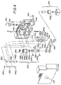
- Figure 4 is an exploded isometric view of the components of the aperture setting apparatus of the invention;
- Figure 5 is a front view of the components of Figure 4 assembled without the front cover in place; and
- Figure 6 is a perspective view of the steel band employed in the apparatus of Figures 4 and 5.
-
- Referring to Figure 1, it depicts a simplified schematic perspective view of the components of one type of an illumination control system of the invention in combination with certain elements of the telecine scanner that are similar to Figure 1 of the '596 patent and Figure 11 of commonly assigned US-
A-5 241 459 patent filed June 1, 1992, to Kaplan et al. - The depicted illumination system includes a 300W Cermax Xenon short arc lamp in a
lamphouse 14 powered by a variable drive,linear power supply 16 that emits a light beam in anoptical path 20 through a normallyopen shutter 22 and condensinglens 24. The light beam in theoptical path 20 is shaped to be circular in cross section by a series of condensinglenses spectral filters filter wheel 40 is interposed in theoptical path 20 so that one of the three depicted sets of film-specific custom interference filters mounted in the wheel can be selected for calibration and for scanning of Eastman Color Negative and Eastman Color Positive films to effect proper color balance to the type of film scanned in a manner described in the above referenced SPIE article and the '379 patent. After calibration, if necessary, the selected filter set is positioned in the optical path for the duration of the telecine scanning operation in response to a signal from the illuminationcontrol system console 70. - Referring to Figure 2 and in accordance with the present invention, an
aperture defining mechanism 33, rapidly and precisely controllable to provide a plurality of aperture openings in a plurality of aperture defining positions, is provided in theoptical path 20, preferably positioned midway between an aperture stop and a field stop with respect to thelenses aperture defining mechanism 33 comprises a pair ofmovable blades aperture 39 centered in theoptical path 20 that is operated to shape the light beam and modulate the beam power level in a manner to be described hereafter. A position sensor (not shown) provides a position signal to the illuminationcontrol system console 70, and theconsole 70 provides a drive current signal to the drive motor of theblades - The
light beam 21 passing through theaperture 39 inoptical path 20 is filtered by the selected filter set infilter wheel 40, shaped by the condensinglenses cylinder 80, which is preferably of the type described in detail in the above referenced US-A-5 241 459 patent, but may be of the type described in the above referenced '346, '383 and '596 patents and SPIE article. Thelight integrating cylinder 80 has a light conducting rod orfiber 81 coupled to a feedback port thereof and to a photosensor 83 which in turn is coupled to a current-to-voltage circuit withinconsole 70 for developing a measured light intensity signal of light within the cavity of the integratingcylinder 80. The measured illumination level is converted to a current value by the photosensor 83 that is in turn converted to a voltage value of the measured light intensity signal. - The integrating
cylinder 80 of Figure 1 is preferably tilted with respect to theoptical path 20 and constructed with an end entrance port (obstructed from view) for admitting thelight beam 21. Thelight beam 21 is carefully adjusted for its angular divergence and its angular orientation relative to the axis and physical characteristics of the integratingcylinder 80 so as to provide uniform light output through thelinear exit port 85. The admittedlight beam 21 is reflected within the integrating cylinder and exits thelinear exit port 85 as a narrow line of intense, diffuse light which falls on the image frames ofmovie film 44 transported past theexit port 85 in the direction "A". - The line of light is modulated in color and Intensity by the image dye color and density, and the modulated line is directed to a
pickup stage 45. Aprojection lens 46 directs the line of light onto abeam splitter 48, including a dichroic filter, and which splits the so modulated line image into chrominance and luminance or detail line images directed onrespective pickup devices Pickup devices - The HDTV telecine conversion system, for which the illumination system of Figure 1 is intended to be used, is designed to accommodate a wide range of movie film types, as itemized in Table I of the '596 patent. The variation in format, perforations, and speed translate into differences in the integration time of the CCD elements of the
linear arrays aperture 85 of the light integrating cylinder 80) must be separated by better than 50 db to avoid flicker artifacts in the video image. Also as lamp power is increased above the normal operating range to enhance the S/N level, lamp life is shortened. - Thus, modulation of lamp current is limited to regulating power level in a narrow operating range that can be employed to respond to low frequency, low magnitude level disturbances primarily caused by lamp arc flicker. This control is accomplished by comparing the measured illumination level in the integrating cylinder to the desired level and using the error value to drive the variable lamp power supply toward zero error in a classic servo regulator configuration.
- To achieve wide dynamic range of illumination, the light
beam obstructing blades optical path 20 as shown in enlarged detail in Figure 2 in place of the aperture wheel described in the '596 patent. Thesethin blades optical path 20 midway between an aperture stop and a field stop plane prior to the integratingcylinder 80 and betweenlenses cylinder 80 of the type described in the above-referenced US-A-5 241 459 patent are minimally affected. In the other alternative embodiments employing the light integrating cylinders of the above referenced '596 patent and SPIE article, placement of the blades is not as sensitive. - At this point in the
optical path 20 of Figure 1, thelight beam 21 is nearly circular in cross section and has a nominal diameter established by the lens system. Theblades aperture 39. The symmetric elliptical and "V"-shaped cut-out blade openings 35' and 37' defining theaperture 39 move symmetrically in mirror image relation relative to each other to cut thelight beam 21 equally from both sides. This preserves the low noise, center light beam characteristic and helps to maintain lengthwise uniformity of light output of the integrating cylinder slit in all of the aperture positions. Moreover, as theaperture 39 is closed, it closes more slowly in the vertical direction than the horizontal direction, preserving vertical light similar to the closure of the iris of a cat's eye. This minimally affects the uniformity of light output at theelongated exit port 85 of thelight integrating cylinder 80. - The
blades position sensor 60 provides absolute position information for use in the blade control. - Control of the position of the
blades - In the US-A-5 528 288 patent first referenced above the control system is described wherein two feedback signals representing the control parameters "intensity level" and "blade position" are employed in servo regulation with respect to corresponding illumination level and blade position reference values. Illumination intensity error and position error signals are derived which are respectively gain shaped by respective intensity and position gain signals. The intensity gain signal is non-linear and varies as a function of aperture position. The position gain signal is a fixed, linear amplification factor applied to the position error signal in order to achieve desired dynamic response. Since the two control parameters are not independently controllable, simultaneous servo regulator control would conflict. This is avoided by always setting either intensity gain or position gain to zero, effectively disabling the respective servo regulator, during differing states of operation.
- The near Gaussian nature of the beam power level from point to point outward from its center C and along its radius R creates a very non-linear relationship between change in beam power level transmission through the aperture versus aperture position change as depicted in the curves of Figure 3. The transmission curves depicted are derived given the Xenon lamp Gaussian beam power distribution and are shown as a function of blade position which increases in value with each blade moving equally from outside the beam toward the center C.
- The transmission characteristics of a pair of blades with straight beam intercepting edges (i.e., without the openings 35' and 37' and similar conceptually to the spiral opening of the aperture wheel of the '596 patent) is shown in the solid line curve in Figure 3. This transmission curve exhibits a very large change in intensity gain as blade position changes, where such intensity gain is defined as the incremental change in illumination level versus change in blade position. The straight edge shape also provides a very high sensitivity of beam intensity change to blade position in the low transmission operating region (i.e. nearing totally closed aperture), especially when measured in the F-stop, or logarithmic, domain.
- In accordance with a preferred embodiment of the invention, the
aperture opening 39 of theblades - The preferred embodiment of the
aperture setting apparatus 33 is depicted in Figures 4 and 5, wherein theblades steel band 233 shown separately in Figure 6. Thesteel band 233 has solid, flat, center sections and cut-out, loop, end sections as shown. The solid,flat sections steel band 233 are bounded by shaped sides 235' and 237' that have the same shape as the openings 35' and 37' described above that allow the light beam to pass through theaperture 39 defined whensteel band sections solid sections openings narrow loop sections - As illustrated in Figure 2, the shaped sides 235' and 237' of the cut-out
openings aperture opening 39 for the illumination beam to pass through. The near Gaussian nature of the illumination beam distribution creates a non-linear relationship between change in beam power versus aperture position change. As described above, the aperture opening is shaped to improve or lower the ratio of maximum to minimum gain, where gain is the change in intensity error with respect to position as described above. Also, the aperture shape improves resolution by lowering the sensitivity to aperture position errors in the low transmission region at or near the fully closed aperture position. - Turning to Figures 4 and 5, the
aperture setting apparatus 33 includes a box-shaped, die casthousing 240 and afront metal cover 270, each having alignedaperture openings steel band 233 is mounted for movement by an internally contained drive and idler mechanism. In thehousing 240, the cut-outband loop sections idler assembly 246 including the bearing races 2461, 2462, respectively. Thesolid band sections drive motor assembly 248 rotates thedrive shaft 244 and thereby moves thesteel band 233 to draw the shaped sides 235' and 237' toward and away from one another from a center point of the alignedaperture openings pin stop 245 attached tohousing 240 interferes with the drive assembly to prevent rotation of thedrive shaft 244 beyond the limited working range. - The
thin steel band 233 is wrapped around the motor drive spools 2441, 2442, over a further pair of first andsecond idlers races races stationary axle 252 that is mounted by shoulder screws 2541, 2542 to thehousing 240. The shoulder screws 2541, 2542 allow the slotted ends of theaxle 252 to be biased by springs (255, 2552) away from the drive spools 2441, 2442 and provide constant band tension across the entire band height. - The first and
second idlers outer races solid section 235 on one side of theband 233 and guide the front andrear band sections such idler steel band 233 rotate to achieve a low mass. - Consequently, the
steel band 233 and the drive spools 2441, 2442 and the tension and return idler mountedbearings drive motor assembly 248. To maintain long life, the thickness of thesteel band 233 and the bending radius about the idlers and drive spools are carefully specified to ensure that the bend radii are greater than minimum specified for the steel band. - In this regard, the
steel band 233 cut-outs oropenings steel band 233 to allow higher acceleration and are further shaped to remove the clock spring effect of the loop portions of the band as it passes over the drive spools and the idlers. This clock spring effect arises if unequal areas of the steel band are bent on the driven end and the idler end as the drive spools are rotated. Such a clock spring effect would provide a constant load force on the motor and the control system affecting dynamic response and accuracy. The drive motor would be forced to expend energy countering the clock spring effect to maintain the commanded aperture opening, raising its temperature and reducing its ability to respond as frequently to commanded light intensity changes, thus lowering the operating duty cycle. - The
drive motor assembly 248 includes an unframed, limited angle, high torque, drive motor 248' is mounted to thedrive shaft 244 to provide the torque required for rotation to the drive spools 2441 and 2442. The motor 248' is preferably a single winding, toroidally wound device that supplies a flat torque profile over the angle of excursion necessary to move thesteel band 233 and the shaped side 235' and 237' between full open to full closed aperture positions. The radii of the motor drive spools 2441, 2442 are sized to provide linear motion of thesteel band 233 within the motor working range. Since the motor 248' is a single winding device, no commutation is required, avoiding commutation noise and torque disturbance. The motor 248' is driven by a matched linear power amplifier to further minimize the potential for noise emission. - Accuracy in steering or movement of the
steel band 233 must be maintained to insure precision and speed in changing and maintaining the aperture opening designated by the control system. Stable, non-slipping position is maintained by two sets of two registration pins (2663, 2664, 2665, 2666) and an attachment screw 2641, 2642 on the respective drive spools 2441, 2442 and registration pins 2661, 2662 on the respective tension and returnidlers loop sections loop sections steel band 233 shown in Figure 6. The band is thereby attached so that it cannot slip off from the drive and idler mechanism. - The tension exerted by the spring loaded, tension and return
idler races steel band 233 provides a stiff drive from the motor drive spools 2441, 2442 to theaperture opening 39 position. This allows the high response servo regulator based control system described in the above referenced US-A-5 528 288 patent to be implemented. - A rotary variable differential transformer (RVDT) 256 is coupled by a
coupling 258 to thedrive shaft 244 attached to the motor drive spools 2441, 2442. TheRVDT 256 is a limited angle device providing a linear output over a limited angle of rotation matched to the system angular range and provides a continuous feedback signal of the absolute position of thesteel band 233 which is attached to the motor drive spools 2441, 2442. TheRVDT 256 contains no wearing elements other than bearings and provides continuous information allowing near infinite resolution. TheRVDT 256 may be a model R30D obtained from Lucas Schaevitz, Corp. Position information could also be provided by an optical encoder with the appropriate change in control electronics. - Other items depicted in Figure 4 include a
thermostat 280 attached tohousing 240 to monitor the temperature of the motor housing. An excessive temperature may be detected and the system may be shut down to avoid damage to the motor. - In use, the low
mass steel band 233 is driven back and forth by the high torque motor 248' to allow fast changes in position comparable to film frame rates. The actual position of theband 233, that correlates to the size of the aperture defined by the shaped side surfaces 235', 237', is detected by theRVDT 256. By providing near real time illumination control in the telecine that adjusts the illumination level of the light beam within one film frame scanning interval (e.g. 33 milliseconds), the video system can repeat the previous or succeeding scanned video frame in place of the transition frame. Illumination levels can thus be changed without the need to stop the video or film transport system and without creating a video image with a transitioning light level. - Although this device was designed to work within the illumination control system described in the above referenced US-A-5 528 288 patent, it could be used in other illumination systems either with or without any modifications. And, the aperture shape effected by the shaped sidewalls 135' and 137' could be altered for this and for other applications.
- The invention having been described in detail with particular reference to the preferred embodiments thereof, it will be understood that variations and modifications can be effected within the scope of the invention as claimed.
Claims (7)
- Aperture setting apparatus for selectively adjusting the amount of light in response to a commanded light intensity signal (96) in a generally circular light beam (20) provided along an optical path, said light beam (20) exhibiting a non-linear relationship between light beam power level and distance from the center of the light beam (20), characterized by:a housing (240) positioned in said optical path having a housing opening (242, 272) for passing said light beam (20) therethrough;a single continuous band (233) formed of a light weight, stiff, light obstructing material with first and second straight, closely spaced, parallel band sections (35, 37; 235, 237) of a predetermined width each connected to the other through first and second end loop end sections (2391, 2392, 2411, 2412) of said continuous band (233), said first and second loop end sections (2391, 2392, 2411, 2412) formed by respective first and second cut-out sections (239, 241) centrally disposed across the width of said band (233) and extending into said parallel band sections (35, 37; 235, 237) to form first and second shaped leading side edges (2351, 2371) and further first and second trailing side edges (235'', 237'') of said parallel light obstructing band sections (35, 37; 235, 237), said first and second leading side edges (2351, 2371) shaped to define first and second symmetric, partially elliptical, blade openings of an aperture opening (39), each elliptical blade opening having a further centrally disposed V-shaped opening extending in the direction of movement of said single continuous band (233) that at least partially compensates for said non-linear relationship of said light beam (20) at a plurality of aperture openings (39) and reduces the ratio of maximum to minimum non-linear system gain and lowers the sensitivity to aperture position errors in the low transmission region which allows finer resolution of aperture openings (39);first and second supporting means (244, 246) for supporting said first and second loop end sections (2391, 2392, 2411, 2412) in said housing (240) opening so that said first and second shaped leading side edges (2351, 2371) face one another and interrupt said light beam (20) in near the same plane to define an aperture opening (39); anddrive means (248) coupled with said supporting means (244, 246) and operable in response to the drive signal for selectively moving said first and second light obstructing band sections (35, 37; 235, 237) in parallel with respect to one another and said housing opening (242, 272) to one of a plurality of aperture openings (39) for obstructing said light beam (20) as a function of the overlap of said first and second leading side edges (2351, 2371) of said first and second parallel light obstructing band sections (35, 37; 235, 237).
- The aperture setting apparatus of Claim 1, wherein said drive means (248) is further characterized by a drive motor (2481) responsive to a commanded light intensity signal for imparting rotational force through said second loop end section (2411, 2412) to drive said band (233) and move said first and second shaped leading edges (2351, 2371) to an aperture opening (39).
- The aperture setting apparatus of Claim 2, wherein said drive motor (2481) is coupled to rotate said second supporting means (244) through a limited angle to thereby drive said single continuous band (233) and move said shaped first and second leading side edges (2351, 2371) to an aperture opening (39).
- The aperture setting apparatus of any of the preceding Claims 1-3, wherein said supporting means (244, 246) is further characterized by:first means (2501, 2502) supported by said housing (240) for engaging and providing rotational and tensioning support for said first loop end section (2391, 2392); andsecond means (2441, 2442) supported by said housing (240) and coupled with said driving means for engaging and providing rotational driving force to said second loop end section (2411, 2412).
- The aperture setting apparatus of any of the preceding Claims 1-4, further characterized by guide means (260, 262) coupled to said housing (240) for guiding said first and second light obstructing band (233) sections (35, 37; 235, 237) in parallel alignment with respect to one another and across said housing opening (242, 272).
- The aperture setting apparatus of any of the preceding Claims 1-5 further characterized by position detecting means (60) for providing a position signal reflecting the aperture opening (39).
- The aperture setting apparatus of any of the preceding Claims 1-6 employed in an illumination system for a film telecine scanner (Fig. 1) adapted to illuminate the image frames of a film (44) and to derive video image frame data from the illuminated image frames within a predetermined frame scanning time interval, of the type comprising illumination means (80) located in said optical path for receiving said light beam (20) from said light source (14) and for illuminating the image frames of the film (44) with diffuse, uniform illumination, and wherein said housing (240) is positioned in said optical path for passing said light beam (20) from said light source (14) to said illumination means (80) in one of said plurality of aperture openings (39) defined by the positions of said first and second light obstructing band sections (35, 37; 235, 237).
Applications Claiming Priority (2)
| Application Number | Priority Date | Filing Date | Title |
|---|---|---|---|
| US08/073,820 US5414460A (en) | 1993-06-08 | 1993-06-08 | Mechanical aperture for controlling illumination level |
| US73820 | 1993-06-08 |
Publications (3)
| Publication Number | Publication Date |
|---|---|
| EP0632651A2 EP0632651A2 (en) | 1995-01-04 |
| EP0632651A3 EP0632651A3 (en) | 1995-06-28 |
| EP0632651B1 true EP0632651B1 (en) | 2000-03-01 |
Family
ID=22115996
Family Applications (1)
| Application Number | Title | Priority Date | Filing Date |
|---|---|---|---|
| EP94107950A Expired - Lifetime EP0632651B1 (en) | 1993-06-08 | 1994-05-24 | Mechanical aperture for controlling illumination level |
Country Status (4)
| Country | Link |
|---|---|
| US (1) | US5414460A (en) |
| EP (1) | EP0632651B1 (en) |
| JP (1) | JPH0715659A (en) |
| DE (1) | DE69423142T2 (en) |
Families Citing this family (6)
| Publication number | Priority date | Publication date | Assignee | Title |
|---|---|---|---|---|
| EP0632650B1 (en) * | 1993-06-08 | 1999-02-03 | Eastman Kodak Company | Illumination control system for a film scanner |
| JPH1132342A (en) * | 1997-07-09 | 1999-02-02 | Sony Corp | Light control device |
| US6542179B1 (en) * | 1998-09-30 | 2003-04-01 | Eastman Kodak Company | Light integrating system with reduced dynamic shading |
| US20010052932A1 (en) * | 1999-12-30 | 2001-12-20 | Young Robert S. | Digital film processing method and system |
| WO2016183098A1 (en) * | 2015-05-11 | 2016-11-17 | Reald Inc. | High dynamic range, high contrast projection systems |
| DE102018122428A1 (en) * | 2018-09-13 | 2020-03-19 | Osram Opto Semiconductors Gmbh | METHOD FOR CONTROLLING LIGHTING OF AN OBJECT, SYSTEM FOR CONTROLLING LIGHTING OF AN OBJECT, AND CAMERA |
Family Cites Families (27)
| Publication number | Priority date | Publication date | Assignee | Title |
|---|---|---|---|---|
| US4118714A (en) * | 1974-07-18 | 1978-10-03 | Canon Kabushiki Kaisha | Light metering system for a photographic camera |
| US3980407A (en) * | 1975-01-17 | 1976-09-14 | Electromask, Inc. | Shutter plate movement |
| US3962707A (en) * | 1975-03-19 | 1976-06-08 | Eastman Kodak Company | Camera diaphragm with follow focus control |
| JPS55105479A (en) * | 1979-02-06 | 1980-08-13 | Sony Corp | Automatic diaphragm device |
| JPS59148471A (en) * | 1983-02-14 | 1984-08-25 | Asahi Optical Co Ltd | Stop device of electronic camera |
| US4531820A (en) * | 1983-06-22 | 1985-07-30 | Polaroid Corporation | Electromagnetic actuator generating equal and opposing force vectors |
| US4592632A (en) * | 1984-12-28 | 1986-06-03 | Walter Renold | Motion picture shutter method and apparatus |
| US4710013A (en) * | 1985-10-08 | 1987-12-01 | W. Haking Enterprises Limited | Automatic focusing mechanism for camera |
| US4727427A (en) * | 1986-10-23 | 1988-02-23 | Polaroid Corporation | Electronic imaging camera system with phosphor image receiving and storing device |
| US4884091A (en) * | 1987-10-08 | 1989-11-28 | Nippon Seimitsu Kogyo Kabushiki Kaisha | Exposure control device in a camera |
| US5023723A (en) * | 1988-04-18 | 1991-06-11 | Canon Kabushiki Kaisha | Image sensing apparatus having plural image sensors and plural shutters |
| US4875103A (en) * | 1988-08-19 | 1989-10-17 | Eastman Kodak Company | Apparatus and method for aligning a repositionable imaging sensor with a photographic image in a film video system |
| US4959728A (en) * | 1988-08-31 | 1990-09-25 | Canon Kabushiki Kaisha | Interchangeable lens and interchangeable lens system |
| US4868383A (en) * | 1988-09-08 | 1989-09-19 | Eastman Kodak Company | Linear integrating cavity light source used for generating an intense beam of light |
| US4899040A (en) * | 1988-09-08 | 1990-02-06 | Eastman Kodak Company | Light-conditioning apparatus for an image scanner illumination system |
| US5049985A (en) * | 1988-10-13 | 1991-09-17 | Canon Kabushiki Kaisha | Color images reading apparatus having transformation table formed base on average values of plural color component signals |
| JPH02239782A (en) * | 1989-03-14 | 1990-09-21 | Canon Electron Inc | Luminous quantity controller |
| US5038216A (en) * | 1989-04-20 | 1991-08-06 | Eastman Kodak Company | Automatic brightness algorithm in a slide to video transfer unit |
| US5122880A (en) * | 1989-05-29 | 1992-06-16 | Canon Kabushiki Kaisha | Electronic still camera with lessened power consumption |
| US5084754A (en) * | 1989-09-20 | 1992-01-28 | Sony Corporation | Method and apparatus for effecting fuzzy control of an imaging device |
| DE69028368T2 (en) * | 1989-09-27 | 1997-03-27 | Canon Kk | Camera system for changing object control |
| US5012346A (en) * | 1989-10-16 | 1991-04-30 | Eastman Kodak Company | Illumination system for a film scanner |
| US5003379A (en) * | 1989-10-16 | 1991-03-26 | Eastman Kodak Company | Telecine scanning apparatus with spectrally-shifted sensitivities responsive to negative or print film dyes |
| JP2773337B2 (en) * | 1989-12-29 | 1998-07-09 | ソニー株式会社 | Video signal conversion method |
| JP3092951B2 (en) * | 1990-06-18 | 2000-09-25 | オリンパス光学工業株式会社 | Endoscope diaphragm device |
| US5155596A (en) * | 1990-12-03 | 1992-10-13 | Eastman Kodak Company | Film scanner illumination system having an automatic light control |
| CA2058396C (en) * | 1990-12-25 | 1995-05-30 | Osamu Sato | Light-quantity control device |
-
1993
- 1993-06-08 US US08/073,820 patent/US5414460A/en not_active Expired - Lifetime
-
1994
- 1994-05-24 EP EP94107950A patent/EP0632651B1/en not_active Expired - Lifetime
- 1994-05-24 DE DE69423142T patent/DE69423142T2/en not_active Expired - Fee Related
- 1994-06-07 JP JP6125537A patent/JPH0715659A/en active Pending
Also Published As
| Publication number | Publication date |
|---|---|
| DE69423142T2 (en) | 2000-09-28 |
| EP0632651A2 (en) | 1995-01-04 |
| JPH0715659A (en) | 1995-01-17 |
| US5414460A (en) | 1995-05-09 |
| EP0632651A3 (en) | 1995-06-28 |
| DE69423142D1 (en) | 2000-04-06 |
Similar Documents
| Publication | Publication Date | Title |
|---|---|---|
| EP0632650B1 (en) | Illumination control system for a film scanner | |
| US8860891B2 (en) | Method and apparatus for increasing effective contrast ratio and brightness yields for digital light valve image projectors | |
| US5155596A (en) | Film scanner illumination system having an automatic light control | |
| JP3762431B2 (en) | Illumination system for color image projection | |
| EP0834231B1 (en) | Back lit electronic viewfinder | |
| US20020050987A1 (en) | Display device | |
| JP2008139857A (en) | Display device | |
| US5414460A (en) | Mechanical aperture for controlling illumination level | |
| US7748854B2 (en) | Image display device | |
| JP4107318B2 (en) | Display device | |
| EP0942607B1 (en) | image projecting apparatus | |
| JP4023125B2 (en) | Illumination apparatus, projection display apparatus, and driving method thereof | |
| US20050146520A1 (en) | Color adjustment for clipped pixels | |
| US7360902B2 (en) | System and method for light source modulation | |
| US6980276B2 (en) | Luminous source apparatus, image projecting apparatus and image projection converting apparatus | |
| JPH11194386A (en) | Light adjusting device and image input device | |
| JPS60202431A (en) | Television camera device |
Legal Events
| Date | Code | Title | Description |
|---|---|---|---|
| PUAI | Public reference made under article 153(3) epc to a published international application that has entered the european phase |
Free format text: ORIGINAL CODE: 0009012 |
|
| AK | Designated contracting states |
Kind code of ref document: A2 Designated state(s): DE FR GB |
|
| PUAL | Search report despatched |
Free format text: ORIGINAL CODE: 0009013 |
|
| AK | Designated contracting states |
Kind code of ref document: A3 Designated state(s): DE FR GB |
|
| 17P | Request for examination filed |
Effective date: 19951202 |
|
| 17Q | First examination report despatched |
Effective date: 19980220 |
|
| GRAG | Despatch of communication of intention to grant |
Free format text: ORIGINAL CODE: EPIDOS AGRA |
|
| GRAG | Despatch of communication of intention to grant |
Free format text: ORIGINAL CODE: EPIDOS AGRA |
|
| GRAH | Despatch of communication of intention to grant a patent |
Free format text: ORIGINAL CODE: EPIDOS IGRA |
|
| GRAH | Despatch of communication of intention to grant a patent |
Free format text: ORIGINAL CODE: EPIDOS IGRA |
|
| GRAA | (expected) grant |
Free format text: ORIGINAL CODE: 0009210 |
|
| AK | Designated contracting states |
Kind code of ref document: B1 Designated state(s): DE FR GB |
|
| REF | Corresponds to: |
Ref document number: 69423142 Country of ref document: DE Date of ref document: 20000406 |
|
| ET | Fr: translation filed | ||
| PLBE | No opposition filed within time limit |
Free format text: ORIGINAL CODE: 0009261 |
|
| STAA | Information on the status of an ep patent application or granted ep patent |
Free format text: STATUS: NO OPPOSITION FILED WITHIN TIME LIMIT |
|
| 26N | No opposition filed | ||
| REG | Reference to a national code |
Ref country code: GB Ref legal event code: IF02 |
|
| PGFP | Annual fee paid to national office [announced via postgrant information from national office to epo] |
Ref country code: GB Payment date: 20050406 Year of fee payment: 12 |
|
| PGFP | Annual fee paid to national office [announced via postgrant information from national office to epo] |
Ref country code: FR Payment date: 20050517 Year of fee payment: 12 |
|
| PGFP | Annual fee paid to national office [announced via postgrant information from national office to epo] |
Ref country code: DE Payment date: 20050531 Year of fee payment: 12 |
|
| PG25 | Lapsed in a contracting state [announced via postgrant information from national office to epo] |
Ref country code: GB Free format text: LAPSE BECAUSE OF NON-PAYMENT OF DUE FEES Effective date: 20060524 |
|
| PG25 | Lapsed in a contracting state [announced via postgrant information from national office to epo] |
Ref country code: DE Free format text: LAPSE BECAUSE OF NON-PAYMENT OF DUE FEES Effective date: 20061201 |
|
| GBPC | Gb: european patent ceased through non-payment of renewal fee |
Effective date: 20060524 |
|
| REG | Reference to a national code |
Ref country code: FR Ref legal event code: ST Effective date: 20070131 |
|
| PG25 | Lapsed in a contracting state [announced via postgrant information from national office to epo] |
Ref country code: FR Free format text: LAPSE BECAUSE OF NON-PAYMENT OF DUE FEES Effective date: 20060531 |