EP0631920A2 - Control device for at least two electrical consumers arranged in a railway vehicle - Google Patents
Control device for at least two electrical consumers arranged in a railway vehicle Download PDFInfo
- Publication number
- EP0631920A2 EP0631920A2 EP94890111A EP94890111A EP0631920A2 EP 0631920 A2 EP0631920 A2 EP 0631920A2 EP 94890111 A EP94890111 A EP 94890111A EP 94890111 A EP94890111 A EP 94890111A EP 0631920 A2 EP0631920 A2 EP 0631920A2
- Authority
- EP
- European Patent Office
- Prior art keywords
- control device
- multiplex
- consumers
- consumer
- power supply
- Prior art date
- Legal status (The legal status is an assumption and is not a legal conclusion. Google has not performed a legal analysis and makes no representation as to the accuracy of the status listed.)
- Ceased
Links
Images


Classifications
-
- B—PERFORMING OPERATIONS; TRANSPORTING
- B61—RAILWAYS
- B61L—GUIDING RAILWAY TRAFFIC; ENSURING THE SAFETY OF RAILWAY TRAFFIC
- B61L15/00—Indicators provided on the vehicle or vehicle train for signalling purposes ; On-board control or communication systems
- B61L15/0018—Communication with or on the vehicle or vehicle train
- B61L15/0027—Radio-based, e.g. using GSM-R
-
- B—PERFORMING OPERATIONS; TRANSPORTING
- B61—RAILWAYS
- B61L—GUIDING RAILWAY TRAFFIC; ENSURING THE SAFETY OF RAILWAY TRAFFIC
- B61L15/00—Indicators provided on the vehicle or vehicle train for signalling purposes ; On-board control or communication systems
- B61L15/0018—Communication with or on the vehicle or vehicle train
- B61L15/0036—Conductor-based, e.g. using CAN-Bus, train-line or optical fibres
-
- B—PERFORMING OPERATIONS; TRANSPORTING
- B61—RAILWAYS
- B61L—GUIDING RAILWAY TRAFFIC; ENSURING THE SAFETY OF RAILWAY TRAFFIC
- B61L15/00—Indicators provided on the vehicle or vehicle train for signalling purposes ; On-board control or communication systems
- B61L15/0081—On-board diagnosis or maintenance
-
- G—PHYSICS
- G08—SIGNALLING
- G08C—TRANSMISSION SYSTEMS FOR MEASURED VALUES, CONTROL OR SIMILAR SIGNALS
- G08C15/00—Arrangements characterised by the use of multiplexing for the transmission of a plurality of signals over a common path
-
- B—PERFORMING OPERATIONS; TRANSPORTING
- B60—VEHICLES IN GENERAL
- B60L—PROPULSION OF ELECTRICALLY-PROPELLED VEHICLES; SUPPLYING ELECTRIC POWER FOR AUXILIARY EQUIPMENT OF ELECTRICALLY-PROPELLED VEHICLES; ELECTRODYNAMIC BRAKE SYSTEMS FOR VEHICLES IN GENERAL; MAGNETIC SUSPENSION OR LEVITATION FOR VEHICLES; MONITORING OPERATING VARIABLES OF ELECTRICALLY-PROPELLED VEHICLES; ELECTRIC SAFETY DEVICES FOR ELECTRICALLY-PROPELLED VEHICLES
- B60L2200/00—Type of vehicles
- B60L2200/26—Rail vehicles
Definitions
- the invention relates to a control device for at least two electrical consumers arranged in a rail vehicle, each of which is connected to a power supply line via an actuator, each actuator being controllable by a central control unit.
- Known control devices for consumers in a rail vehicle generally have a central control unit which is connected to a central switching unit in which, for example, an actuator is provided for each consumer, which is connected to the associated consumer via a stub line.
- the signals supplied by the control unit are thus processed in the central switching unit, after which the stub lines leading to the specific consumers are switched on or off, for example via contactor switches.
- Such a known device is sold, for example, by the applicant under the name BK / 1 system.
- an infrared free-beam transmission device for vehicles in which signals are transmitted unidirectionally via a plurality of transmission channels to the infrared receivers, which are arranged in the area of the dashboard, and which are spatially distributed in the interior cabin of the Vehicle are arranged. Multiple reflections on the inner walls are said to improve the signal-to-noise ratio.
- a disadvantage of this device is, inter alia, that the transmission system is very susceptible to interference and also requires special spatial conditions, such as certain reflection properties of the inner walls etc. Furthermore, in many cases a unidirectional signal connection does not offer the required transmission security.
- the central control unit for controlling the at least two consumers is assigned a multiplex transmitter system, which is connected via a multiplex connection to a respective multiplex receiver for each actuator to be controlled and spatially adjacent to the associated consumer.
- each consumer which is assigned to the central control unit, can be controlled by means of a single connection between this central control unit and the at least two consumers.
- control device results from the fact that the multiplex connection is either an electrical or optical line or an infrared or radio link.
- the multiplex connection is at the same time the power supply line for the consumer. In this embodiment, no additional wiring of the rail vehicle is required.
- the actuators are advantageously switches with a built-in multiplex receiver, the central control unit being set up to selectively switch the consumers on and off via the connected multiplex transmitter system and the multiplex connection.
- a simple form of fault diagnosis is made possible by the fact that the central control unit is set up for sequential, selective switching on and off of individual consumers of a group of consumers and for measuring the current in a line leading to this group of consumers.
- the control device can be used to control a number of consumers of a rail vehicle.
- consumers are the lighting (e.g. compartment, toilet, aisle and emergency lighting), display and signaling devices, as well as heaters (e.g. duct, entry room, toilet and post-heating elements) supply air, pressure protection and exhaust air fans, drives for Air flaps, drives for automatic doors, solenoid valves in air conditioning systems and vacuum toilets as well as other electrical machines such as compressors or condenser fan motors.
- a control device which has a central control unit 1, which is connected via a bus 2 to a multiplex transmission system 3.
- the bus 2 is a company-specific serial bus with the designation AF-485 installed in the rail vehicle and transmits the signals supplied by the central control unit 1 to the multiplex transmitter system 3, which uses a multiplex connection 4 with each actuator 5 1, 5 2 to be controlled.
- 53, ..., 510 is connected, each of these actuators 51, 52, 53, ..., 510 each having a multiplex receiver.
- Each multiplex receiver integrated in an actuator 5 forms part of a decentralized demultiplex system which, due to the peripheral design, is distributed to all actuators, so that in the present case no separate demultiplex device is required.
- Each actuator 51, 52, 53, ..., 510 is arranged directly on a consumer 61, 62, 63, ..., 610, each consumer being connected to a power supply line 7 via such an actuator.
- Typical power supplies for rail vehicles are, for example, a 24V DC network for lighting, controls, displays and signaling devices or a 380/220 AC network for heating and ventilation.
- the present exemplary embodiments according to FIGS. 1 to 3 are a 380 / 220V network, on which a plurality of secondary heating elements are provided as consumers 6 and are arranged in an air supply duct of an air conditioning system. These post-heating elements 6 have the task of preheating supply air flowing into the compartment to a certain temperature.
- This temperature is generally specified via a setpoint switch (not shown) which is connected to the central control unit 1, which in the present case is a central climate control of a rail vehicle.
- the central control unit 1 After processing all the setpoint and actual value data and possibly further data, such as the outside temperature, this central climate control 1 now sends a signal to the multiplex transmitter system 3, which converts this transmitter system into a suitable data packet for multiplex transmission, to the physical conditions of the multiplex Connection 4 adapted and transmitted to the actuators 5 to be controlled via the multiplex connection.
- ten consumers (post-heating element) 6 1, 6 2, 6 3, ..., 6 10 are connected to the multiplex transmitter 3, which are addressed, for example, at a transmission rate of one data packet / second.
- this data packet contains approximately 20 to 30 bits.
- the multiplex signal is assigned to the individual consumers (demultiplexing process) via the position of the bit within the packet, with, for example, a set bit switching on the consumer and an unset bit causing this consumer to be switched off, or vice versa .
- the consumers 6 connected to the multiplex system must be registered in the central control unit 1.
- Another advantage of a control device according to the invention is that simple consumers, such as afterheating, can be effectively diagnosed without additional effort. With such a diagnosis, which is advantageously carried out automatically each time the control device is switched on in the sense of a self-test, a consumer is switched on sequentially, the current flow caused in the power supply line being measured and communicated to the central control unit. If the measured value for the respective consumer current falls below or exceeds a certain value, the central control unit issues an error message, indicating the type of error that has occurred and the consumer concerned.
- the multiplex connection is either an electrical or an optical line.
- the electrical line can be, for example, a single signal line provided for this purpose.
- an optical waveguide is arranged in the rail vehicle, which is connected on the transmitter side to a controllable light source and on the receiver side to an optical detector.
- a laser diode is used as the light source, a photodiode being used as the detector.
- Such data transmission is characterized by great immunity to interference.
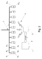
- FIG. 2 shows an embodiment of the invention in which the multiplex connection is either an infrared or a radio link.
- the multiplex transmitter system has an infrared or radio signal transmitter and the multiplex receiver has an infrared detector or a radio signal receiver.
- the embodiment with an infrared path is preferably used for visual contact between the transmitter and receiver. In the case of large distances between the transmitter and receiver, in particular if the receiver is installed or covered, the embodiment with a radio link as a multiplex connection is recommended.
- FIG. 3 shows a further embodiment of the invention, in which the power supply line 7 is simultaneously used as a multiplex connection.
- the control signal from the multiplex transmitter system is coupled into the supply line and is coupled out again from the multiplex receivers.
- An embodiment variant for such a coupling or decoupling of the control signal is shown schematically in FIG. 4.
- the individual consumers 61, 62, ..., 610 are each via a controlled switch S1, S2, ..., S10 on an electrical supply line 7, which is fed by an electrical energy source U v with an internal resistance R V with electrical current , whereby this supply line also serves for signal transmission.
- the control signal U0 is coupled from the multiplex transmitter 3 via a capacitor C0 into the supply / signal line 4, 7, the frequency of the control signal U0 being many times higher than the frequency of the supply voltage.
- the frequency of the supply voltage is typically 0 Hz (DC voltage) or 50 Hz (380/220 AC voltage), whereas the frequency with which the control signal is transmitted is on the order of a few 10 kHz to a few 100 kHz or higher.
- the control signal is again coupled out via a capacitor C1, C2, ..., C10 from the supply / signal line 4, 7 and each one actuator 51, 52, ..., 510, which each has an assigned switch S1, S2 , ..., S10 (for example a triac) operated.
- each inductor L1, L2, ..., L10 is connected in series with each consumer 61, 62, ..., 610, so that the resistance for the higher-frequency control signal is greater, for example, by a factor of 10 to 100 than for the low-frequency power supply. This results in a significant reduction in the influence of the consumer resistances on the load on the control signal source U0, R0 and thus a better detectability of the control signal on the actuators, as well as a fail-safe operation of the control device according to the invention.
- an inductor L V is also connected in series with the electrical power supply U V for this purpose, so that the path of the control signal U 0 in the direction of the power supply U V becomes higher-impedance and thus further signal losses can be avoided.
- These inductors can be used with particular advantage in the case of low-resistance consumers such as post-heating elements.
- control signals U0 to be transmitted in this embodiment are advantageously transmitted via a carrier signal which is optionally either frequency or phase modulated.
- a carrier signal which is optionally either frequency or phase modulated.
- Frequency-modulated signal transmission is easier to implement, whereas phase modulation ensures greater immunity to interference.
Abstract
Description
Gegenstand der Erfindung ist eine Steuerungsvorrichtung für zumindest zwei in einem Schienenfahrzeug angeordnete elektrische Verbraucher, die über je ein Stellglied an eine Stromversorgungsleitung angeschlossen sind, wobei jedes Stellglied von einer zentralen Steuereinheit ansteuerbar ist.The invention relates to a control device for at least two electrical consumers arranged in a rail vehicle, each of which is connected to a power supply line via an actuator, each actuator being controllable by a central control unit.
Bekannte Steuerungsvorrichtungen für Verbraucher in einem Schienenfahrzeug weisen in der Regel eine zentrale Steuereinheit auf, welche mit einer zentralen Schalteinheit verbunden ist, in welcher beispielsweise für jeden Verbraucher je ein Stellglied vorgesehen ist, welches über je eine Stichleitung mit dem zugeordneten Verbraucher verbunden ist. Die von der Steuereinheit gelieferten Signale werden somit in der zentralen Schalteinheit verarbeitet, wonach die zu den bestimmten Verbrauchern führenden Stichleitungen, beispielsweise über Schützschalter zu- oder weggeschaltet werden. Eine solche bekannte Vorrichtung wird beispielsweise von der Anmelderin unter der Bezeichnung BK/1-System vertrieben.Known control devices for consumers in a rail vehicle generally have a central control unit which is connected to a central switching unit in which, for example, an actuator is provided for each consumer, which is connected to the associated consumer via a stub line. The signals supplied by the control unit are thus processed in the central switching unit, after which the stub lines leading to the specific consumers are switched on or off, for example via contactor switches. Such a known device is sold, for example, by the applicant under the name BK / 1 system.
Ein Nachteil dieser bekannten Steuerungsvorrichtungen liegt unter anderem darin, daß für die zentrale Schalteinheit in den Schaltschränken eines Schienenfahrzeuges viel Platz beansprucht wird. Weiters ist die Verkabelung der Verbraucher aufwendig, da von jedem Schalter in der zentralen Schalteinheit je ein Kabel zu jedem Verbraucher geführt werden muß. Da die Schalteinheit und der anzusteuernde Verbraucher bei Schienenfahrzeugen vielfach weit voneinander entfernt sind, entstehen dadurch hohe Verkabelungskosten.One disadvantage of these known control devices is that a lot of space is required for the central switching unit in the switch cabinets of a rail vehicle. Furthermore, the cabling of the consumers is complex, since from each switch in the central switching unit one cable must be led to each consumer. Since the switching unit and the consumer to be controlled in rail vehicles are often far apart, this leads to high cabling costs.
Ein wesentlicher Nachteil der langen Stichleitungen zwischen Stellglied und Verbraucher, welche oft über mehrere Klemmen und Stecker geführt werden, besteht in der potentiellen Gefahr von Leitungskurzschlüssen im Betrieb und bei Wartungsarbeiten, wodurch insbesondere elektronische Stellglieder wie Halbleiterrelais zerstört werden können oder aber durch aufwendige Maßnahmen geschützt werden müssen.A major disadvantage of the long stub lines between the actuator and the consumer, which are often routed through several terminals and plugs, is the potential risk of line short-circuits during operation and maintenance work, which in particular can destroy electronic actuators such as solid-state relays or protect them by complex measures have to.
Aus der DE-OS 41 26 840 ist eine Infrarot-Freistrahl-Übertragungsvorrichtung für Fahrzeuge bekannt geworden, bei welcher Signale durch einen im Bereich des Armaturenbrettes angeordneten Infrarotsender unidirektional über eine Mehrzahl von Sendekanälen zu den Infrarotempfängern übertragen werden, welche räumlich verteilt in der Innenkabine des Fahrzeuges angeordnet sind. Durch Vielfachreflexionen an den Innenwänden soll sich eine Verbesserung des Störabstandes ergeben. Ein Nachteil dieser Vorrichtung liegt unter anderem darin, daß das Übertragungssystem sehr störungsanfällig ist und besondere räumliche Verhältnisse ebenso voraussetzt, wie bestimmte Reflexionseigenschaften der Innenwände etc. Weiters bietet eine unidirektionale Signalverbindung in vielen Fällen nicht die erforderliche Übertragungssicherheit.From DE-OS 41 26 840 an infrared free-beam transmission device for vehicles has become known, in which signals are transmitted unidirectionally via a plurality of transmission channels to the infrared receivers, which are arranged in the area of the dashboard, and which are spatially distributed in the interior cabin of the Vehicle are arranged. Multiple reflections on the inner walls are said to improve the signal-to-noise ratio. A disadvantage of this device is, inter alia, that the transmission system is very susceptible to interference and also requires special spatial conditions, such as certain reflection properties of the inner walls etc. Furthermore, in many cases a unidirectional signal connection does not offer the required transmission security.
Daher ist es eine Aufgabe der Erfindung, eine Steuerungsvorrichtung für zumindest zwei Verbraucher in einem Schienenfahrzeug anzugeben, bei welcher die oben genannten Nachteile, insbesondere hohe Verkabelungskosten, die Zerstörungsgefahr durch Leitungskurzschlüsse oder etwaige Übertragungsfehler vermieden werden.It is therefore an object of the invention to provide a control device for at least two consumers in a rail vehicle, in which the above-mentioned disadvantages, in particular high cabling costs, the risk of destruction due to line short circuits or any transmission errors are avoided.
Diese Aufgabe wird dadurch gelöst, daß der zentralen Steuereinheit zur Ansteuerung der zumindest zwei Verbraucher eine Multiplex-Sendeanlage zugeordnet ist, welche über eine Multiplex-Verbindung mit je einem Multiplexempfänger für jedes anzusteuernde, dem zugehörigen Verbraucher räumlich benachbarte Stellglied verbunden ist. Durch diese Maßnahme kann jeder Verbraucher, welcher der zentralen Steuereinheit zugeordnet ist, anhand einer einzigen Verbindung zwischen dieser zentralen Steuereinheit und den zumindest zwei Verbrauchern angesteuert werden.This object is achieved in that the central control unit for controlling the at least two consumers is assigned a multiplex transmitter system, which is connected via a multiplex connection to a respective multiplex receiver for each actuator to be controlled and spatially adjacent to the associated consumer. With this measure, each consumer, which is assigned to the central control unit, can be controlled by means of a single connection between this central control unit and the at least two consumers.
Vorteilhafte Ausführungsformen einer erfindungsgemäßen Steuerungsvorrichtung ergeben sich dadurch, daß die Multiplex-Verbindung entweder eine elektrische oder optische Leitung oder eine Infrarot- bzw. Funkstrecke ist.Advantageous embodiments of a control device according to the invention result from the fact that the multiplex connection is either an electrical or optical line or an infrared or radio link.
Bei einer besonders vorteilhaften Ausführungsform der Erfindung ist die Multiplex-Verbindung gleichzeitig die Stromversorgungsleitung für den Verbraucher. Bei dieser Ausführungsform entfällt jede zusätzliche Verkabelung des Schienenfahrzeuges.In a particularly advantageous embodiment of the invention, the multiplex connection is at the same time the power supply line for the consumer. In this embodiment, no additional wiring of the rail vehicle is required.
In vorteilhafter Weise sind die Stellglieder Schalter mit eingebautem Multiplexempfänger, wobei die zentrale Steuereinheit zum selektiven Ein- und Ausschalten der Verbraucher über die angeschlossene Multiplex-Sendeanlage und die Multiplex-Verbindung eingerichtet ist.The actuators are advantageously switches with a built-in multiplex receiver, the central control unit being set up to selectively switch the consumers on and off via the connected multiplex transmitter system and the multiplex connection.
Eine einfache Form der Fehlerdiagnose wird dadurch ermöglicht, daß die zentrale Steuereinheit zum sequentiellen, selektiven Ein- und Ausschalten einzelner Verbraucher einer Gruppe von Verbrauchern sowie zur Messung des Stromes in einer zu dieser Gruppe von Verbrauchern führenden Leitung eingerichtet ist.A simple form of fault diagnosis is made possible by the fact that the central control unit is set up for sequential, selective switching on and off of individual consumers of a group of consumers and for measuring the current in a line leading to this group of consumers.
Die erfindungsgemäße Steuerungsvorrichtung kann zum Ansteuern einer Reihe von Verbrauchern eines Schienenfahrzeuges verwendet werden. Beispielsweise sind solche Verbraucher die Beleuchtung (z.B. Abteil-, WC-, Gang- und Notbeleuchtung), Anzeige- und Meldeeinrichtungen, sowie Heizungen (z.B. Kanal-, Einstiegsraum-, WC- und Nachheizkörper) Zuluft-, Druckschutz- und Fortluftventilatoren, Antriebe für Luftklappen, Antriebe für automatische Türen, Magnetventile in Klimaanlagen und Vakuumtoiletten sowie andere elektrische Maschinen wie Kompressoren oder Kondensatorlüftermotoren.The control device according to the invention can be used to control a number of consumers of a rail vehicle. For example, such consumers are the lighting (e.g. compartment, toilet, aisle and emergency lighting), display and signaling devices, as well as heaters (e.g. duct, entry room, toilet and post-heating elements) supply air, pressure protection and exhaust air fans, drives for Air flaps, drives for automatic doors, solenoid valves in air conditioning systems and vacuum toilets as well as other electrical machines such as compressors or condenser fan motors.
Weitere Ausgestaltungsmerkmale und Vorteile der Erfindung ergeben sich aus der folgenden Beschreibung eines Ausführungsbeispiels der Erfindung. Darin wird auf die beiliegenden Figuren bezug genommen, die zeigen:
- Figur 1 ein Blockschaltbild einer erfindungsgemäßen Steuerungsvorrichtung,
Figur 2 ein Blockschaltbild einer Ausführungsform einer erfindungsgemäßen Steuerungsvorrichtung, bei welcher die Multiplex-Verbindung eine Funk- bzw. Infrarotstrecke ist,Figur 3 ein Blockschaltbild einer weiteren Ausführungsform einer erfindungsgemäßen Steuerungsvorrichtung, bei welcher die Multiplex-Verbindung die Stromversorgungsleitung ist,Figur 4 ein elektrisches Detailschaltbild der Ausführungsform gemäßFigur 3.
- FIG. 1 shows a block diagram of a control device according to the invention,
- FIG. 2 shows a block diagram of an embodiment of a control device according to the invention, in which the multiplex connection is a radio or infrared link,
- FIG. 3 shows a block diagram of a further embodiment of a control device according to the invention, in which the multiplex connection is the power supply line,
- FIG. 4 shows an electrical detailed circuit diagram of the embodiment according to FIG. 3.
In den Figuren 1, 2 und 3 ist eine erfindungsgemäße Steuerungsvorrichtung dargestellt, welche eine zentrale Steuereinheit 1 aufweist, die über einen Bus 2 mit einer Multiplex-Sendeanlage 3 verbunden ist. Der Bus 2 ist ein in dem Schienenfahrzeug installierter firmenspezifischer serieller Bus mit der Bezeichnung AF-485 und überträgt die von der zentralen Steuereinheit 1 gelieferten Signale an die Multiplex-Sendeanlage 3, die über eine Multiplex-Verbindung 4 mit jedem anzusteuernden Stellglied 5₁, 5₂, 5₃, ..., 5₁₀ verbunden ist, wobei jedes dieser Stellglieder 5₁, 5₂, 5₃, ..., 5₁₀ je einen Multiplexempfänger aufweist. Jeder in einem Stellglied 5 integrierte Multiplexempfänger bildet einen Teil einer dezentralen Demultiplex-Anlage, die aufgrund der peripheren Konzeption auf alle Stellglieder verteilt ist, sodaß im vorliegenden Fall keine gesonderte Demultiplex-Vorrichtung erforderlich ist.1, 2 and 3, a control device according to the invention is shown, which has a central control unit 1, which is connected via a
Jedes Stellglied 5₁, 5₂, 5₃, ..., 5₁₀ ist unmittelbar an je einem Verbraucher 6₁, 6₂, 6₃, ..., 6₁₀ angeordnet, wobei jeder Verbraucher über je ein solches Stellglied mit einer Stromversorgungsleitung 7 verbunden ist. Typische Stromversorgungen für Schienenfahrzeuge sind beispielsweise ein 24V Gleichstromnetz für Beleuchtung, Steuerungen, Anzeige und Meldeeinrichtungen oder ein 380/220 Wechselstromnetz, für Heizung und Lüftung. Bei den vorliegenden Ausführungsbeispielen gemäß der Figuren 1 bis 3 handelt es sich um ein 380/220V Netz, an welchem als Verbraucher 6 eine Mehrzahl von Nachheizkörpern vorgesehen sind, die in einem Zuluftkanal einer Klimaanlage angeordnet sind. Diese Nachheizkörper 6 haben die Aufgabe, in das Abteil einströmende Zuluft auf eine bestimmte Temperatur vorzuwärmen. Diese Temperatur wird im allgemeinen über einen (nicht dargestellten) Sollwertschalter vorgegeben, der mit der zentralen Steuereinheit 1 verbunden ist, die im vorliegenden Fall eine zentrale Klimasteuerung eines Schienenfahrzeuges ist. Diese zentrale Klimasteuerung 1 liefert nun nach Verarbeitung aller Sollwert- und Istwertdaten und gegebenenfalls weiterer Daten, wie die Außentemperatur, ein Signal an die Multiplex-Sendeanlage 3, welches von dieser Sendeanlage für die Multiplexübertragung in ein geeignetes Datenpaket verwandelt, an die physikalischen Gegebenheiten der Multiplex-Verbindung 4 angepaßt und über die Multiplex-Verbindung an die anzusteuernden Stellglieder 5 übertragen wird.Each
Im vorliegenden Fall sind an die Multiplex-Sendeanlage 3 zehn Verbraucher (Nachheizkörper) 6₁, 6₂, 6₃, ..., 6₁₀ angeschlossen, die beispielsweise mit einer Übertragungsrate von einem Datenpaket/Sekunde angesprochen werden. Dieses Datenpaket enthält bei einer einfachen Ausführungsform einschließlich Synchronisation und Fehlersicherung ca. 20 bis 30 Bit. Bei einer solchen Ausführungsform erfolgt die Zuordnung des Multiplex-Signals zu den einzelnen Verbrauchern (Demultiplex-Vorgang) über die Position des Bits innerhalb des Paketes, wobei beispielsweise ein gesetztes Bit das Einschalten des Verbrauchers und ein nicht gesetztes Bit ein Abschalten dieses Verbrauchers bewirkt oder umgekehrt. Zu diesem Zweck müssen jedoch die an das Multiplex-System angeschlossenen Verbraucher 6 in der zentralen Steuereinheit 1 registriert sein.In the present case, ten consumers (post-heating element) 6 1, 6 2, 6 3, ..., 6 1₀ are connected to the
Ein weiterer Vorteil einer erfindungsgemäßen Steuerungsvorrichtung liegt darin, daß bei einfachen Verbrauchern, wie z.B. Nachheizkörper, ohne Zusatzaufwand eine wirksame Fehlerdiagnose durchgeführt werden kann. Bei einer solchen Diagnose, die vorteilhafterweise bei jedem Einschalten der Steuerungsvorrichtung im Sinne eines Selbsttests automatisch durchgeführt wird, wird sequentiell jeweils ein Verbraucher eingeschaltet, wobei der in der Stromversorgungsleitung hervorgerufene Stromfluß gemessen und der zentralen Steuereinheit mitgeteilt wird. Wenn der gemessene Wert für den jeweiligen Verbraucherstrom einen bestimmten Wert unter- oder überschreitet, wird von der zentralen Steuereinheit eine Fehlermeldung ausgegeben, wobei die Art des aufgetretenen Fehlers und der betroffene Verbraucher angegeben werden.Another advantage of a control device according to the invention is that simple consumers, such as afterheating, can be effectively diagnosed without additional effort. With such a diagnosis, which is advantageously carried out automatically each time the control device is switched on in the sense of a self-test, a consumer is switched on sequentially, the current flow caused in the power supply line being measured and communicated to the central control unit. If the measured value for the respective consumer current falls below or exceeds a certain value, the central control unit issues an error message, indicating the type of error that has occurred and the consumer concerned.
Bei der in Figur 1 dargestellten Ausführungsform der Erfindung ist die Multiplex-Verbindung entweder eine elektrische oder eine optische Leitung. Die elektrische Leitung kann beispielsweise eine einzige, dafür vorgesehene Signalleitung sein. Bei der Ausführungsform, bei welcher als Multiplex-Verbindung eine optische Leitung vorgesehen ist, wird in dem Schienenfahrzeug ein Lichtwellenleiter angeordnet, welcher senderseitig an eine steuerbare Lichtquelle und empfängerseitig an je einen optischen Detektor angeschlossen ist. Als Lichtquelle dient im vorliegenden Fall eine Laserdiode, wobei als Detektor eine Photodiode verwendet wird. Eine solche Datenübertragung zeichnet sich durch große Störsicherheit aus.In the embodiment of the invention shown in FIG. 1, the multiplex connection is either an electrical or an optical line. The electrical line can be, for example, a single signal line provided for this purpose. In the embodiment in which an optical line is provided as a multiplex connection, an optical waveguide is arranged in the rail vehicle, which is connected on the transmitter side to a controllable light source and on the receiver side to an optical detector. In the present case, a laser diode is used as the light source, a photodiode being used as the detector. Such data transmission is characterized by great immunity to interference.
In Figur 2 ist eine Ausführungsform der Erfindung dargestellt, bei welcher die Multiplex-Verbindung entweder eine Infrarot- oder eine Funkstrecke ist. Bei dieser Ausführungsform weist die Multiplex-Sendeanlage einen Infrarot- bzw. Funksignal-Sender und die Multiplexempfänger einen Infrarot-Detektor bzw. einen Funksignal-Empfänger auf. Die Ausführungsform mit einer Infrarotstrecke wird vorzugsweise bei Sichtkontakt zwischen Sender und Empfänger eingesetzt. Bei großen Entfernungen zwischen Sender und Empfänger, insbesondere wenn der Empfänger verbaut oder verdeckt ist, empfiehlt sich die Ausführungsform mit einer Funkstrecke als Multiplex-Verbindung.FIG. 2 shows an embodiment of the invention in which the multiplex connection is either an infrared or a radio link. In this embodiment, the multiplex transmitter system has an infrared or radio signal transmitter and the multiplex receiver has an infrared detector or a radio signal receiver. The embodiment with an infrared path is preferably used for visual contact between the transmitter and receiver. In the case of large distances between the transmitter and receiver, in particular if the receiver is installed or covered, the embodiment with a radio link as a multiplex connection is recommended.
Figur 3 zeigt eine weitere Ausführungsform der Erfindung, bei welcher die Stromversorgungsleitung 7 gleichzeitig als Multiplex-Verbindung verwendet wird. Bei dieser Ausführungsform wird das Steuersignal von der Multiplex-Sendeanlage in die Versorgungsleitung eingekoppelt und von den Multiplexempfängern wieder ausgekoppelt. Eine Ausführungsvariante für ein solches Ein- bzw. Auskoppeln des Steuersignals ist in Figur 4 schematisch dargestellt. Die einzelnen Verbraucher 6₁, 6₂, ..., 6₁₀ liegen über je einen gesteuerten Schalter S₁, S₂, ..., S₁₀ an einer elektrischen Versorgungsleitung 7, die von einer elektrischen Energiequelle Uv mit einem Innenwiderstand RV mit elektrischem Strom gespeist wird, wobei diese Versorgungsleitung gleichzeitig zur Signalübertragung dient. Das Steuersignal U₀ wird von der Multiplex-Sendeanlage 3 über einen Kondensator C₀ in die Versorgungs/Signalleitung 4, 7 eingekoppelt, wobei die Frequenz des Steuersignals U₀ um ein Vielfaches höher ist, als die Frequenz der Versorgungsspannung. Die Frequenz der Versorgungsspannung liegt typischerweise bei 0 Hz (Gleichspannung) oder bei 50 Hz (380/220 Wechselspannung), wogegen die Frequenz, mit welcher das Steuersignal übertragen wird, in der Größenordnung von einigen 10 kHz bis einigen 100 kHz oder darüber liegt. Empfängerseitig wird das Steuersignal wieder über je einen Kondensator C₁, C₂, ..., C₁₀ aus der Versorgungs/Signalleitung 4, 7 ausgekoppelt und je einem Stellglied 5₁, 5₂, ..., 5₁₀ zugeführt, welches je einen zugeordneten Schalter S₁, S₂, ..., S₁₀ (beispielsweise einen Triac) betätigt.FIG. 3 shows a further embodiment of the invention, in which the
Zusätzlich ist bei der vorliegenden Ausführungsform in Serie mit jedem Verbraucher 6₁, 6₂, ..., 610 je eine Induktivität L₁, L₂, ..., L₁₀ geschaltet, sodaß der Widerstand für das höherfrequente Steuersignal beispielsweise um einen Faktor 10 bis 100 größer ist, als für die niederfrequente Stromversorgung. Dadurch ergibt sich eine wesentliche Verminderung des Einflusses der Verbraucherwiderstände auf die Belastung der Steuersignalquelle U₀, R₀ und somit eine bessere Detektierbarkeit des Steuersignals an den Stellgliedern, sowie ein störungssicherer Betrieb der erfindungsgemäßen Steuerungsvorrichtung. Weiters ist ebenso zu diesem Zweck in Serie mit der elektrischen Stromversorgung UV eine Induktivität LV geschaltet, sodaß der Pfad des Steuersignals U₀ in Richtung Stromversorgung UV hochohmiger wird und somit weitere Signalverluste vermieden werden können. Diese Induktivitäten sind insbesondere bei niederohmigen Verbrauchern wie Nachheizkörpern vorteilhaft einsetzbar.In addition, in the present embodiment, each inductor L₁, L₂, ..., L₁₀ is connected in series with each
Die bei dieser Ausführungsform zu übertragenden Steuersignale U₀ werden vorteilhafterweise über ein Trägersignal übertragen, das wahlweise entweder frequenz- oder phasenmoduliert ist. Eine frequenzmodulierte Signalübertragung ist einfacher zu realisieren, wogegen eine Phasenmodulation eine höhere Störsicherheit gewährleistet.The control signals U₀ to be transmitted in this embodiment are advantageously transmitted via a carrier signal which is optionally either frequency or phase modulated. Frequency-modulated signal transmission is easier to implement, whereas phase modulation ensures greater immunity to interference.
Claims (17)
Applications Claiming Priority (2)
| Application Number | Priority Date | Filing Date | Title |
|---|---|---|---|
| AT128193A AT401980B (en) | 1993-06-30 | 1993-06-30 | CONTROL DEVICE FOR AT LEAST TWO ELECTRICAL CONSUMERS ARRANGED IN A RAIL VEHICLE |
| AT1281/93 | 1993-06-30 |
Publications (2)
| Publication Number | Publication Date |
|---|---|
| EP0631920A2 true EP0631920A2 (en) | 1995-01-04 |
| EP0631920A3 EP0631920A3 (en) | 1997-07-09 |
Family
ID=3510496
Family Applications (1)
| Application Number | Title | Priority Date | Filing Date |
|---|---|---|---|
| EP94890111A Ceased EP0631920A3 (en) | 1993-06-30 | 1994-06-29 | Control device for at least two electrical consumers arranged in a railway vehicle. |
Country Status (2)
| Country | Link |
|---|---|
| EP (1) | EP0631920A3 (en) |
| AT (1) | AT401980B (en) |
Cited By (2)
| Publication number | Priority date | Publication date | Assignee | Title |
|---|---|---|---|---|
| DE19856539C2 (en) * | 1998-12-08 | 2001-11-08 | Deutsche Bahn Ag | Data communication system on the train with master bus |
| WO2021224078A1 (en) * | 2020-05-05 | 2021-11-11 | Siemens Mobility GmbH | Arrangement for capturing the state of an electronic circuit |
Citations (4)
| Publication number | Priority date | Publication date | Assignee | Title |
|---|---|---|---|---|
| US3532228A (en) * | 1969-04-25 | 1970-10-06 | Dresser Ind | Electronic control and surveillance system for railway trains |
| US4041470A (en) * | 1976-01-16 | 1977-08-09 | Industrial Solid State Controls, Inc. | Fault monitoring and reporting system for trains |
| US4682144A (en) * | 1983-04-07 | 1987-07-21 | Mitsubishi Denki Kabushiki Kaisha | Light transmission system for trains |
| FR2625390A1 (en) * | 1987-12-29 | 1989-06-30 | Eaton Corp | FIBER OPTIC MULTIPLEXING COMMUNICATION APPARATUS |
Family Cites Families (1)
| Publication number | Priority date | Publication date | Assignee | Title |
|---|---|---|---|---|
| DE4126840A1 (en) * | 1991-08-14 | 1993-02-18 | Daimler Benz Ag | IR remote control system for vehicle - uses dashboard transmitter and spaced receivers within passenger space for respective actuators |
-
1993
- 1993-06-30 AT AT128193A patent/AT401980B/en active
-
1994
- 1994-06-29 EP EP94890111A patent/EP0631920A3/en not_active Ceased
Patent Citations (4)
| Publication number | Priority date | Publication date | Assignee | Title |
|---|---|---|---|---|
| US3532228A (en) * | 1969-04-25 | 1970-10-06 | Dresser Ind | Electronic control and surveillance system for railway trains |
| US4041470A (en) * | 1976-01-16 | 1977-08-09 | Industrial Solid State Controls, Inc. | Fault monitoring and reporting system for trains |
| US4682144A (en) * | 1983-04-07 | 1987-07-21 | Mitsubishi Denki Kabushiki Kaisha | Light transmission system for trains |
| FR2625390A1 (en) * | 1987-12-29 | 1989-06-30 | Eaton Corp | FIBER OPTIC MULTIPLEXING COMMUNICATION APPARATUS |
Cited By (2)
| Publication number | Priority date | Publication date | Assignee | Title |
|---|---|---|---|---|
| DE19856539C2 (en) * | 1998-12-08 | 2001-11-08 | Deutsche Bahn Ag | Data communication system on the train with master bus |
| WO2021224078A1 (en) * | 2020-05-05 | 2021-11-11 | Siemens Mobility GmbH | Arrangement for capturing the state of an electronic circuit |
Also Published As
| Publication number | Publication date |
|---|---|
| ATA128193A (en) | 1996-05-15 |
| AT401980B (en) | 1997-01-27 |
| EP0631920A3 (en) | 1997-07-09 |
Similar Documents
| Publication | Publication Date | Title |
|---|---|---|
| EP1064759B1 (en) | Method for commissioning a bus system and corresponding bus system | |
| DE102005005236B4 (en) | Vehicle with a vehicle electrical system and a plurality of electrical loads | |
| DE19811626A1 (en) | Current supply system for motor vehicles | |
| EP0279168B1 (en) | Circuit for the power supply of a multitude of consumers | |
| EP1967393B1 (en) | Electric trailer connection device | |
| EP1999001B1 (en) | Device for switching on and monitoring a traffic light installation for rail traffic | |
| WO2013076087A1 (en) | Test system and test method for cable harnesses | |
| EP3475132A1 (en) | Modular hydraulic braking system and a method for data transmission for a rail vehicle | |
| EP2633738B1 (en) | Combination of an on-board power supply control device and at least one light control device of a motor vehicle | |
| AT401980B (en) | CONTROL DEVICE FOR AT LEAST TWO ELECTRICAL CONSUMERS ARRANGED IN A RAIL VEHICLE | |
| EP1055547B1 (en) | Control system for the drive components of a railway vehicle | |
| DE19948969A1 (en) | Control device for vehicle drive train has electronic components with different high loss powers, those used for gearbox control integrated into gearbox control apparatus | |
| DE102010023145A1 (en) | Photovoltaic system, has protection unit arranged close to electric line from photovoltaic module to inverter device when protection unit receives operating signal corresponding to active control | |
| WO2019086205A1 (en) | Safety monitoring device for monitoring safety-relevant states in a person-transporting system, and method for operating same | |
| DE19813471A1 (en) | Automobile electrical installation regulation, control and safety device | |
| DE4430441C2 (en) | Device for controlling electrical consumers | |
| EP2671746B1 (en) | Lighting system and method for operating a lighting system, in particular for a rail vehicle | |
| EP3305622A1 (en) | Method for diagnosis of spatially distributed technical components | |
| EP0327720A1 (en) | Computer input-output circuit | |
| EP3833589B1 (en) | Control system for a motor vehicle and method for diagnosing a failure in a control system | |
| DE19933688A1 (en) | Electronic control system for rail vehicles has number of distributed controllers coupled over a CAN bus | |
| EP0499658B1 (en) | Electric network of a vehicle for rear light current supply | |
| DE102022209548B3 (en) | Device for controlling at least one high-voltage actuator and vehicle | |
| EP3529101A1 (en) | Electrical device for a rail vehicle | |
| DE102006011170A1 (en) | Consumer switching and protecting device, has actuator module provided with devices and circuit-breakers for controlling/protecting consumer, and decentralized modules for controlling/protecting another consumer |
Legal Events
| Date | Code | Title | Description |
|---|---|---|---|
| PUAI | Public reference made under article 153(3) epc to a published international application that has entered the european phase |
Free format text: ORIGINAL CODE: 0009012 |
|
| AK | Designated contracting states |
Kind code of ref document: A2 Designated state(s): BE DE ES |
|
| PUAL | Search report despatched |
Free format text: ORIGINAL CODE: 0009013 |
|
| AK | Designated contracting states |
Kind code of ref document: A3 Designated state(s): BE DE ES |
|
| 17P | Request for examination filed |
Effective date: 19971223 |
|
| RAP1 | Party data changed (applicant data changed or rights of an application transferred) |
Owner name: LIEBHERR-VERKEHRSTECHNIK GMBH |
|
| 17Q | First examination report despatched |
Effective date: 20000726 |
|
| STAA | Information on the status of an ep patent application or granted ep patent |
Free format text: STATUS: THE APPLICATION HAS BEEN REFUSED |
|
| 18R | Application refused |
Effective date: 20020211 |