EP0631790A2 - Inflatable percutaneous oxygenator with transverse hollow fibers - Google Patents
Inflatable percutaneous oxygenator with transverse hollow fibers Download PDFInfo
- Publication number
- EP0631790A2 EP0631790A2 EP94630030A EP94630030A EP0631790A2 EP 0631790 A2 EP0631790 A2 EP 0631790A2 EP 94630030 A EP94630030 A EP 94630030A EP 94630030 A EP94630030 A EP 94630030A EP 0631790 A2 EP0631790 A2 EP 0631790A2
- Authority
- EP
- European Patent Office
- Prior art keywords
- fibers
- oxygenator
- manifolds
- gas
- balloon
- Prior art date
- Legal status (The legal status is an assumption and is not a legal conclusion. Google has not performed a legal analysis and makes no representation as to the accuracy of the status listed.)
- Granted
Links
Images




Classifications
-
- A—HUMAN NECESSITIES
- A61—MEDICAL OR VETERINARY SCIENCE; HYGIENE
- A61M—DEVICES FOR INTRODUCING MEDIA INTO, OR ONTO, THE BODY; DEVICES FOR TRANSDUCING BODY MEDIA OR FOR TAKING MEDIA FROM THE BODY; DEVICES FOR PRODUCING OR ENDING SLEEP OR STUPOR
- A61M1/00—Suction or pumping devices for medical purposes; Devices for carrying-off, for treatment of, or for carrying-over, body-liquids; Drainage systems
- A61M1/14—Dialysis systems; Artificial kidneys; Blood oxygenators ; Reciprocating systems for treatment of body fluids, e.g. single needle systems for hemofiltration or pheresis
- A61M1/16—Dialysis systems; Artificial kidneys; Blood oxygenators ; Reciprocating systems for treatment of body fluids, e.g. single needle systems for hemofiltration or pheresis with membranes
- A61M1/1678—Dialysis systems; Artificial kidneys; Blood oxygenators ; Reciprocating systems for treatment of body fluids, e.g. single needle systems for hemofiltration or pheresis with membranes intracorporal
-
- A—HUMAN NECESSITIES
- A61—MEDICAL OR VETERINARY SCIENCE; HYGIENE
- A61M—DEVICES FOR INTRODUCING MEDIA INTO, OR ONTO, THE BODY; DEVICES FOR TRANSDUCING BODY MEDIA OR FOR TAKING MEDIA FROM THE BODY; DEVICES FOR PRODUCING OR ENDING SLEEP OR STUPOR
- A61M1/00—Suction or pumping devices for medical purposes; Devices for carrying-off, for treatment of, or for carrying-over, body-liquids; Drainage systems
- A61M1/14—Dialysis systems; Artificial kidneys; Blood oxygenators ; Reciprocating systems for treatment of body fluids, e.g. single needle systems for hemofiltration or pheresis
- A61M1/16—Dialysis systems; Artificial kidneys; Blood oxygenators ; Reciprocating systems for treatment of body fluids, e.g. single needle systems for hemofiltration or pheresis with membranes
- A61M1/1698—Blood oxygenators with or without heat-exchangers
-
- A—HUMAN NECESSITIES
- A61—MEDICAL OR VETERINARY SCIENCE; HYGIENE
- A61M—DEVICES FOR INTRODUCING MEDIA INTO, OR ONTO, THE BODY; DEVICES FOR TRANSDUCING BODY MEDIA OR FOR TAKING MEDIA FROM THE BODY; DEVICES FOR PRODUCING OR ENDING SLEEP OR STUPOR
- A61M1/00—Suction or pumping devices for medical purposes; Devices for carrying-off, for treatment of, or for carrying-over, body-liquids; Drainage systems
- A61M1/14—Dialysis systems; Artificial kidneys; Blood oxygenators ; Reciprocating systems for treatment of body fluids, e.g. single needle systems for hemofiltration or pheresis
- A61M1/16—Dialysis systems; Artificial kidneys; Blood oxygenators ; Reciprocating systems for treatment of body fluids, e.g. single needle systems for hemofiltration or pheresis with membranes
- A61M1/26—Dialysis systems; Artificial kidneys; Blood oxygenators ; Reciprocating systems for treatment of body fluids, e.g. single needle systems for hemofiltration or pheresis with membranes and internal elements which are moving
-
- Y—GENERAL TAGGING OF NEW TECHNOLOGICAL DEVELOPMENTS; GENERAL TAGGING OF CROSS-SECTIONAL TECHNOLOGIES SPANNING OVER SEVERAL SECTIONS OF THE IPC; TECHNICAL SUBJECTS COVERED BY FORMER USPC CROSS-REFERENCE ART COLLECTIONS [XRACs] AND DIGESTS
- Y10—TECHNICAL SUBJECTS COVERED BY FORMER USPC
- Y10S—TECHNICAL SUBJECTS COVERED BY FORMER USPC CROSS-REFERENCE ART COLLECTIONS [XRACs] AND DIGESTS
- Y10S128/00—Surgery
- Y10S128/03—Heart-lung
-
- Y—GENERAL TAGGING OF NEW TECHNOLOGICAL DEVELOPMENTS; GENERAL TAGGING OF CROSS-SECTIONAL TECHNOLOGIES SPANNING OVER SEVERAL SECTIONS OF THE IPC; TECHNICAL SUBJECTS COVERED BY FORMER USPC CROSS-REFERENCE ART COLLECTIONS [XRACs] AND DIGESTS
- Y10—TECHNICAL SUBJECTS COVERED BY FORMER USPC
- Y10S—TECHNICAL SUBJECTS COVERED BY FORMER USPC CROSS-REFERENCE ART COLLECTIONS [XRACs] AND DIGESTS
- Y10S261/00—Gas and liquid contact apparatus
- Y10S261/28—Blood oxygenators
Definitions
- the present invention relates generally to gas transfer devices and more particularly to a percutaneous intravenous oxygenator utilizing hollow gas permeable fibers.
- oxygenators are well-known in the art.
- the patient is interconnected with an external oxygenator, commonly known as a heart-lung machine, which introduces oxygen into the blood system.
- Most types of oxygenators use a gas permeable liquid impermeable membrane. Blood flows along one side of the membrane, and oxygen is supplied to the other side of the membrane. Given a sufficient pressure gradient between the oxygen supply and the blood, the oxygen will diffuse through the membrane and into the blood. In addition, carbon dioxide will tend to diffuse from the blood through the membrane.
- a smaller, implantable oxygenator may be sufficient to adequately supplement the patient's cardiopulmonary function by marginally increasing the oxygen content of the patient's blood.
- patients suffering from emphysema, pneumonia, congested heart failure, or other chronic lung disease often have blood oxygen partial pressures of approximately 40 torr.
- a relatively small increase of 10% to 20% is generally sufficient to adequately maintain the patient. This is a particularly desirable alternative in that it avoids the need to intubate the patient in such cases.
- temporary use of this type of oxygenator is sufficient in many cases to tie the patient over in acute respiratory insult. Placing such patients on a conventional respirator is often the beginning of a progressive down hill spiral by damaging the patient's pulmonary tree and thereby causing greater dependence on the respirator.
- the effective rate of diffusion in percutaneous oxygenators can be limited in some instances by the problem of "streaming" or "channeling,” in which the blood stream establishes relatively stable patterns of flow around and through the oxygenator. Portions of the oxygenator are exposed to a relatively high velocity, turbulent flow of blood. These conditions tend to increase cross-diffusion of oxygen and carbon dioxide. However, other portions of the oxygenator are exposed to a low velocity, laminar flow of blood which reduces diffusion of gases. Those portions of the oxygenator immediately adjacent to the regions of the high blood flow may continue to experience high rates of diffusion, but the remaining portions of the oxygenator tend to have relatively low diffusion rates. Thus, the overall diffusion rate of the oxygenator can be substantially diminished by streaming. A number of devices and processes have been invented in the past relating to different types of oxygenators.
- U.S. Patent No. 3,505,686 to Bodell demonstrates the general concept of using gas permeable fibers to boost the oxygen level of blood.
- the patent discloses several variations of the device wherein it is intended for use inside the body of the patient.
- a tubular casing serves as a shunt either from the pulmonary artery to the left atrium of the heart or more generally between an artery and a vein.
- a multitude of parallel-connected capillary tubes are used to oxygenate and/or purify the blood circulating to the casing.
- U.S. Patent No. 4,583,969 to Mortenson shows a transvenous oxygenator made of a plurality of small diameter gas permeable tubes connected to headers at each end.
- the specific device disclosed by Mortenson has a significant disadvantage in that two incisions are required.
- U.S. patent to Taheri No. 4,631,053 discloses a transvenous oxygenator having a single membrane through which oxygen diffuses.
- the membrane is disposed within a sheath and both are supported by a flexible wire.
- U.S. Patent No. 4,850,958 to Berry, et al. discloses an in vivo extrapulmonary blood gas exchange device having a bundle of elongated gas permeable tubes bound at each end and enclosed within respective air tight proximal and distal chambers.
- a dual lumen tube is situated relative to the gas permeable tubes such that an outer lumen terminates within the proximal chamber and inner lumen terminates within the distal chamber.
- U.S. Patent No. 4,911,689 to Hattler and Patent No. 4,986,809 to Hattler, et al. disclose several embodiments of percutaneous oxygenators.
- oxygen is circulated through a plurality of hollow, gas permeable fibers forming loops and the device is inserted through a single incision into a blood vessel.
- the fiber loops are bisected and placed in fluid communication within a mixing chamber within a tip at the distal end of the device.
- the present invention was developed to improve upon prior art oxygenators of the type that include hollow gas permeable/liquid impermeable membrane fibers that can be inserted into the vena cava to oxygenate blood intravenously. It has been found that the efficiency of such an oxygenators can be improved by minimizing the length of the fibers and/or deploying the fibers so that they do not run longitudinally of the device as in prior art systems. The blood gas transfer is also improved by maintaining constant movement of the gas fibers through use of an inflatable balloon around which the fibers extend.
- Each set of fibers is spirally wound in an opposite direction and surrounds an inflatable balloon which is connected to a gas inflation source for sequentially inflating and deflating the balloon to keep the fibers in constant motion.
- a gas delivery line is connected to the input manifold to deliver gas to the fibers and a vacuum source is attached to the output manifold so that the gas can be drawn through the fibers at a negative pressure.
- an elongated tubular gas delivery manifold is connected to one end of a plurality of gas fibers with the manifold extending longitudinally of the oxygenator.
- a similar elongated tubular gas exhaust manifold is connected to the opposite end of the fibers and the fibers are wrapped around one of the manifolds as well as an inflatable and deflatable balloon so that several layers of the fibers can be wound transversely around the balloon.
- Circumferential displacement of the manifolds in one direction or another serve to increase or decrease the diameter of the oxygenator so that it can be decreased in diameter for easy insertion into the vena cava of a patient and increased in diameter while in the vena cava for optimal gas transfer.
- two sets of gas permeable fibers are interwoven with the fibers of each set extending in parallel relationship with each other and substantially perpendicular to the fibers of the other set.
- One set of fibers extends longitudinally of the device and the other set transversely.
- An elongated semi-rigid manifold is connected in fluid communication to the input end of one set of fibers as well as to a substantially perpendicular but flexible elongated tubular manifold which is connected in communication to the input end of the fibers of the second set.
- a duplicate set of manifolds are connected to the outlet ends of the fibers so that the fibers and the flexible manifolds can be wound around one of the semi-rigid elongated manifolds and a balloon so as to be configured similarly to the second described embodiment.
- twice the number of fibers can be utilized thereby increasing the gas transfer efficiency of the device.
- a fourth embodiment of the invention includes two sets of fibers which have been woven and disposed about an inflatable balloon such that the fibers of each set wrap helically around the balloon.
- An inlet manifold and an outlet manifold are disposed at opposite ends of the device in communication with input and output ends of the fibers respectively so that gas can be delivered to the input ends of the fibers and removed by vacuum from the outlet ends.
- the balloon is again inflatable and deflatable to maintain the fibers in constant motion for optimal gas transfer.
- the manifolds are also longitudinally moveable relative to each other to allow the fibers to expand and contract in a desired manner.
- elongated tubular inlet and outlet manifolds extend longitudinally of the device and are connected to inlet and outlet ends of gas permeable fibers which extend transversely to the manifolds and form a tubular construction of fibers around an interior inflatable balloon.
- Gas is delivered to the inlet manifold and allowed to flow in opposite directions through the fibers and around the tubular body for collection at the outlet manifold which is connected to a vacuum source so that the gas flow can be maintained at a negative pressure.
- Several layers of fibers comprising the tubular body can be provided in alternative arrangements of this embodiment.
- At least three longitudinally spaced manifolds are provided with one of the manifolds being in communication with for example the input ends of two sets of fibers and the other two manifolds being in communication with the output end of both sets of fibers so that gas is transferred in opposite directions from an intermediate location on the device through both sets of fibers.
- the fibers surround inflatable balloons disposed between the manifolds at each end of the oxygenator and the middle manifold.
- a desirable feature of this embodiment is that the fibers are of relatively short length which has also been found to improve the gas delivery efficiency of the fiber membrane oxygenators.
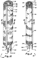
- Fig. 1 is an isometric view of a first embodiment of the present invention.
- Fig. 2 is an enlarged fragmentary longitudinal section taken along line 2-2 of Fig. 1.
- Fig. 3 is a longitudinal fragmentary sections similar to Fig. 2 with the balloon in a deflated condition.
- Fig. 4 is an enlarged transverse section taken along line 4-4 of Fig. 2.
- Fig. 5 is an enlarged fragmentary section taken along line 5-5 of Fig. 3 with parts removed to show the various layers of the oxygenator.
- Fig. 6 is an enlarged fragmentary isometric with parts removed showing various layers of fibers.
- Fig. 7 is a further enlarged fragmentary elevation showing the relationship of various layers of fibers.
- Fig. 8 is an enlarged section taken along line 8-8 of Fig. 2.
- Fig. 9 is an enlarged fragmentary elevation showing the interconnection of adjacent fibers in the oxygenator of Fig. 1.
- Fig. 10 is an isometric view of a second embodiment of the present invention with an alternative arrangement shown in phantom lines.
- Fig. 11 is an isometric view of the oxygenator shown in Fig. 10 in a reduced diameter configuration.
- Fig. 12 is a section taken along line 12-12 of Fig. 10.
- Fig. 13 is a section taken along line 13-13 of Fig. 11.
- Fig. 14 is an enlarged fragmentary section taken through the inlet manifold of the oxygenator of Fig. 10 showing the connection of the manifold to the fibers.
- Fig. 15 is an isometric view of the oxygenator of Fig. 10 in an unrolled state and with the balloon shown in phantom lines in the alternative arrangement.
- Fig. 16 is an isometric view of a balloon used in a third embodiment of the present invention.
- Fig. 17 is an enlarged section taken along line 17-17 of Fig. 16.
- Fig. 18 is an enlarged section taken along line 18-18 of Fig. 16.
- Fig. 19 is an isometric view of the third embodiment of the present invention in an unrolled state and without the internal balloon.
- Fig. 20 is an enlarged section taken through portions of the inlet and outlet manifolds of the oxygenator of Fig. 19 showing their relationship with two interwoven sets of fibers.
- Fig. 21 is an isometric view of a fourth embodiment of the present invention.
- Fig. 22 is an isometric view of the embodiment shown in Fig. 21 in an expanded state.
- Fig. 23 is an enlarged section taken along line 23-23 of Fig. 21.
- Fig. 24 is an enlarged section taken along line 24-24 of Fig. 22.
- Fig. 25 is a further enlarged longitudinal section with parts removed of the embodiment of the invention shown in Fig. 21.
- Fig. 26 is a further enlarged fragmentary elevational view showing the woven relationship of the two sets of fibers utilized in the embodiment illustrated in Fig. 21.
- Fig. 27 is an isometric view of a fifth embodiment of the present invention.
- Fig. 28 is an enlarged section taken along line 28-28 of Fig. 27.
- Fig. 29 is an isometric view with parts removed of a modification to the embodiment shown in Fig. 27.
- Fig. 30 is a section taken along line 30-30 of Fig. 29.
- Fig. 31 is a longitudinal section taken through a sixth embodiment of the present invention positioned within the vena cava and illustrating the heart adjacent thereto.
- Fig. 32 is an enlarged section taken along line 32-32 of Fig. 31.
- Fig. 33 is an enlarged section taken along line 33-33 of Fig. 31.
- Fig. 34 is an enlarged section taken along line 34-34 of Fig. 31.
- Fig. 35 is an enlarged section taken along line 35-35 of Fig. 31.
- Fig. 36 is an enlarged section taken along line 36-36 of Fig. 31.
- a first embodiment 40 of the intravenous percutaneous oxygenator of the present invention can be seen to include a plurality of helically disposed hollow membrane fibers 42 having opposite ends in communication with ring like manifolds 44 and 46 and an internal inflatable balloon 48 disposed within a space 50 defined by the fibers.
- the fibers 42 are commercially available hollow membrane fibers which are gas permeable but liquid impermeable.
- a suitable fiber is manufactured by Mitsubishi and marketed under model no. KPF190M.
- Membrane type oxygenators are characterized in general by the fact that oxygen rich gas will diffuse through the membrane into oxygen deficient blood on the opposite side of the membrane while excess carbon dioxide in the blood will cross-diffuse through the same membrane into the oxygen stream. Accordingly, when a membrane oxygenator is inserted in a blood vessel and oxygen passed therethrough, the oxygen will diffuse through the wall of the fiber membrane thereby oxygenating the blood and simultaneously removing excess carbon dioxide from the blood.
- oxygenator of the present invention could be used in other gas transfer environments such as for example to deliver an anesthetic.
- a better description of this particular alternate use can be found in U.S. Patent No. 5,207,640, which is hereby incorporated by reference.
- the fibers 42 in the oxygenator 40 are actually deployed and helically wound in overlapping fiber mats 52 which consist of a plurality of substantially parallel fibers 42 that are transversely bound together as best shown in Fig. 9 by strands of thread 54 or the like which retain the fibers in a desired spaced relationship.
- Each fiber mat 52 includes a set of fibers having an input end 56 and an output end 58 with the input end of the fibers in each mat being embedded in a suitable potting compound 60 in the input manifold 44 so as to be in fluid communication with a ring-like chamber 62 in the manifold 44 at the proximal end of the oxygenator.
- the opposite or output ends 58 of the fibers in each mat are similarly potted in a suitable potting compound 60 in the output or exhaust manifold 46 so as to be in fluid communication with a ring-like chamber 64 in the exhaust manifold at the distal end of the oxygenator.
- the internal space 50 defined by the helically wound fiber mats 52 and the input and the output manifolds 46 and 48, respectively, functions to position and retain the balloon 48 which is fabricated from a tubular polymer sleeve wherein the ends of the tubular sleeve are hermetically sealed in rubber grommet 66 and 68 or the like.
- the grommet 66 at the proximal end of the balloon surrounds and hermetically confines a gas inflation tube or lumen 70 which communicates with the interior of the balloon and is connected to a source of helium or the like for inflating and deflating the balloon.
- the proximal grommet 66 also surrounds and hermetically confines a vacuum line or lumen 72 which extends through the balloon 48 as well as the grommet 68 at the distal end of the oxygenator before passing through a reverse loop 73 and being potted in the outlet manifold 46 in communication with the ring-like chamber 64 and the output ends of the fibers.
- the vacuum line 72 is connected at its proximal end to a source of vacuum (not shown).
- the input manifold 46 has a gas inlet line or lumen 74 connected thereto which is exposed to a source of oxygen gas.
- the vacuum source connected to the vacuum line 72 serves to draw the oxygen gas into the oxygenator through the inlet manifold 46 where it is allowed to pass through the gas permeable fibers 42 while defusing into the blood.
- the gas mixture accumulating at the outlet manifold 46 which includes not only oxygen that did not diffuse but also carbon dioxide which cross diffused and was removed from the blood, is drawn from the oxygenator 40 through the vacuum line 72.
- the balloon 48 is loosely disposed within the space 50 defined by the fibers so as to be slidable relative to the manifolds 46 and 48. Accordingly, when the balloon inflates, the manifolds can be drawn longitudinally toward each other and when the balloon is deflated, the manifolds can be longitudinally displaced from each other. This arrangement allows the fibers to move desirably for optimal gas transfer.
- each layer of fiber mat passes through approximately 180 degrees between its input and output ends.
- the input ends 56 of each fiber 42 are circumferentially offset approximately 180 degrees from the output ends 58.
- a second embodiment 80 of the present invention is shown in Figs. 10-15 and can be seen to include a fiber mat 82 formed of a plurality of parallel bound fibers 84 and elongated longitudinally extending tubular inlet and outlet manifolds 86 and 88, respectively, connected to opposite ends of the mat for delivering gas to the fibers and removing gas from the fibers.
- the entire mat 82 can be wound in a spiral around one of the manifolds and an interior balloon 90 which is inflatable and deflatable as with the first embodiment.
- the fibers 84 in the fiber mat 82 extend substantially perpendicularly to the longitudinal axis of the oxygenator and are bound together as in the first described embodiment with threads 92 or the like so that the fibers are retained in substantially parallel but spaced relationship for optimal gas transfer.
- the inlet manifold 86 is connected to input ends 94 of each fiber 84 and the output manifold 88 is connected to the output ends 96 of each fiber as best seen in Fig. 14.
- the manifolds are semi-rigid tubes which retain the mat in a substantially extended condition while being flexible enough to be inserted into a vein and follow the contours of the vein.
- the manifolds 86 and 88 are hollow tubular bodies and the fibers are potted in a suitable potting compound 98 in an opening 100 in the side of the manifolds (Fig. 14).
- the inlet manifold 86 is disposed adjacent to the balloon 90 so that the fiber mat is wrapped therearound or whether the outlet manifold 88 is so positioned.
- the inlet manifold 86 is disposed on the outside of the oxygenator 80 and is connected via flexible tubing 102 to a source of oxygen (not shown).
- the outlet manifold 88 is similarly connected with flexible tubing 104 to a vacuum source (not shown) so that the vacuum source can draw the oxygen and any accumulated carbon dioxide through the manifolds and the connected fibers at a negative pressure.
- the balloon 90 which is disposed interiorly of the wrapped fiber mat 82 is inflated and deflated in a conventional manner through a flexible tube 106 which is connected to a source of helium or the like which has been found to be suitable for this purpose.
- the balloon 90 might be connected to one of the manifolds 86 or 88 with a connector 108 which in the disclosed alternative shown in phantom lines in Figs. 10, 11 and 15 is the outlet manifold 88.
- the connection of the balloon to one of the manifolds facilitates simultaneous insertion of the manifolds, mat and balloon.
- the connection does not necessarily have to be made, however, as the balloon can be inserted into the vena cava after the fiber mat is inserted and merely slid into the space 110 defined at the center of the spirally wound fiber mat.
- FIG. 16-20 A third embodiment of the invention is illustrated in Fig. 16-20 with this embodiment being somewhat similar to that disclosed in Figs. 10-15.
- the fibers 112 are woven into a mat 113 so that there are two sets of parallel fibers 112A and 112B with the fibers in each set being substantially perpendicular to the fibers of the other set.
- Each set of fibers has an inlet end 114A or 114B and an opposite outlet end 116A or 116B.
- Manifolds 118 are generally L-shaped having a semi-rigid tubular manifold leg 120 and a perpendicular flexible tubular manifold leg 122.
- the rigid legs 120 are associated with one set of fibers 112A with one rigid leg communicating with the inlet ends 114A of the fibers and the other rigid leg with the outlet ends 116A of the fibers.
- the flexible legs 122 are associated with the second set of fibers 112B with one flexible leg being in communication with the inlet ends 114B of the second set of fibers and the other flexible leg with the outlet ends 116B of the second set of fibers.
- the fibers 112 are suitably connected to the manifolds 118 with a potting compound 124 as shown in Fig. 20.
- One L-shaped manifold is of course connected to a source of oxygen (not shown) through an input line 126 while the other L-shaped manifold is connected to a vacuum source (not shown) through an outlet line 128.
- the woven fiber mat 113 is wound around a balloon 130 configured as shown in Fig. 16 with the semi-rigid manifold leg 120 of each manifold 118 extending longitudinally of the oxygenator and in parallel relationship with the balloon.
- the flexible legs 122 of the manifolds are allowed to be wound into a spiral at proximal and distal ends of the oxygenator respectively.
- the woven mat 113 of fibers is therefore wound in a spiral around the balloon and the diameter of the oxygenator can be varied by moving the semi-rigid manifolds 120 circumferentially relative to each other in one direction or another to facilitate insertion and desired operation of the oxygenator.
- the ability of the semi-rigid manifolds to move circumferentially relative to each other allows the fiber mat 113 to expand and contract when the balloon is inflated and deflated respectively.
- One desired aspect of this embodiment of the invention is the fact that nearly twice the number of fibers can be incorporated into the same mat to increase the surface area of contact between the fibers and the blood to be oxygenated.
- a fourth embodiment 132 of the present invention is illustrated in Figs. 21-25.
- This embodiment can be seen to include a mat 134 woven from two set of fibers 136A and 136B with the fibers 136 in each set being substantially perpendicular to the fibers in the other set and with the sets of fibers being helically wound in opposite directions around the oxygenator.
- the fibers in each set have their inlet and outlet ends 137 and 138, respectively, potted in inlet and outlet manifolds 140 and 142, respectively, located at opposite longitudinal ends of the oxygenator.
- the outlet manifold 142 as best seen in Figs.
- the inlet manifold 140 which is at the proximal end of the oxygenator, is of ring-like configuration having a circular internal chamber 150 in communication with the inlet ends 137 of the fibers of both sets which are potted in the manifold.
- An oxygen supply line 152 is also potted in the inlet manifold 140 to deliver oxygen from an oxygen source (not shown) to the inlet manifold.
- a balloon 154 is formed from tubular polymer material by hermetically sealing opposite ends of the tubular polymer material to the exhaust tube 148 at spaced locations along the length of the exhaust tube.
- the balloon is also hermetically sealed around a gas inflation line 156 which slidably extends through the inlet manifold 140.
- a source of helium gas or the like (not shown) is connected to the inflation line 156 to inflate and deflate the balloon. It should be appreciated that none of the balloon 154, the exhaust tube 148, or the gas inflation line 156 is connected to the inlet manifold so that the manifold 140 is allowed to slide along the length of these components toward and away from the exhaust manifold 142 as the balloon inflates and deflates. This permits the fibers to be moved in and out to optimize gas transfer.
- the fibers 136 include two sets of interwoven fibers 136A and 136B which are disposed at an angle relative to the longitudinal axis of the oxygenator so that each fiber in fact is wrapped helically relative to the longitudinal axis of the oxygenator.
- the fibers tend to be drawn closer to a central longitudinal axis of the oxygenator, whereas when the manifolds are moved longitudinally closer to each other the fibers become further separated from the central longitudinal axis. This increases the turbulence of the blood passing in and around the oxygenator to optimize gas transfer.
- FIG. 27-30 A fifth embodiment of the present invention is illustrated in Figs. 27-30 with a first arrangement 160 shown in Figs. 27 and 28.
- longitudinally extending inlet and outlet manifolds 162 and 164 are of elongated semi-rigid tubular construction and are diametrically disposed on either side of the oxygenator.
- the inlet manifold 162 is connected through an inlet tube 166 to a source of oxygen gas (not shown) while the outlet manifold 164 is connected through an outlet tube 168 to a vacuum source (not shown).
- the fibers 170 are disposed in two sets 170A and 170B with each set being of generally semi-cylindrical configuration and having a plurality of parallel fibers that have been bound together with thread 172 or the like so as to retain the fibers in a spaced relationship and wherein they extend substantially perpendicularly to each of the manifolds.
- the fibers of each set extend away from each manifold in an opposite direction so as to define a tubular body 174 that surrounds an inflatable balloon 176.
- the balloon as in other embodiments is connected to a source of gas (not shown) through a gas supply tube 178 for inflation and deflation with a suitable gas being helium.
- a source of gas not shown
- a gas supply tube 178 for inflation and deflation with a suitable gas being helium.
- elongated tubular semi-rigid input and output manifolds 182 and 184 are again connected to sources of oxygen gas through an input line 186 and a vacuum source through an outlet line 188, respectively.
- this arrangement there are actually four sets of fibers 190 which have been bound together into four mats 190A, 190B, 190C and 190D having inlet and outlet ends 192 and 194, respectively, of the fibers in each mat connected in fluid communication with the inlet and outlet manifolds 182 and 184, respectively.
- the four sets of fibers define in combination two concentric tubular bodies 196 and 198 which surround an internal balloon 200 which again is connected to a gas inflation and deflation source such as helium through a gas supply tube 202.
- a gas inflation and deflation source such as helium
- Figs. 27 and 28 The only difference in this arrangement and that shown in Figs. 27 and 28 is that there is a double layer of thickness of the fibers to increase the surface area of contact between the fibers and the blood flow.
- a sixth embodiment 204 of the present invention is shown in Figs. 31-36 and can be seen to include three longitudinally displaced manifolds 206, 208 and 210 which interconnect two distinct sets 212 and 214 of fibers 216.
- the manifolds 206 and 210 at the opposite ends of the oxygenator serve a common purpose in serving as inlet or outlet manifolds while the middle manifold 208 serves the opposite purpose.
- the middle manifold will be referred to as the inlet manifold and the other manifolds 206 and 210 will be referred to as the proximal end outlet manifold and the distal end outlet manifold, respectively.
- the proximal end outlet manifold 206 of the oxygenator is ring shaped and defines an internal chamber 218 that is in communication with the outlet end 220 of the first set 212 of fibers which have been potted in the manifold.
- the inlet end 222 of the first set of fibers are potted in the inlet manifold 208 which also has a circular hollow chamber 224.
- An oxygen gas inlet line 226 is connected to (in non-fluid communication) and passes through the proximal end outlet manifold 206 and is connected to and communicates with the interior chamber 224 of the inlet manifold 208 for delivering gas to the inlet manifold.
- the gas is thereby allowed to flow in a reverse direction through the first set of fibers for collection in the proximal end outlet manifold 206 where the gas can be removed by a vacuum source connected through a vacuum line 228 to the hollow chamber 218 in the proximal end outlet manifold 206.
- the second set of fibers 214 have their inlet end 230 potted in the inlet manifold 208 again in communication with the interior chamber 224 to receive oxygen gas therefrom and an outlet end 232 potted in the distal end outlet manifold 210 having a hollow chamber 234 in communication with the outlet end of the fibers.
- the vacuum line 228 extends through the proximal end outlet manifold 206, through the inlet manifold 208 (in non-fluid communication), and then opens into the internal chamber 234 in the distal end outlet manifold 210. In this manner, gas collected in the distal end outlet manifold can be returned to the proximal end outlet manifold 206 and subsequently removed from the oxygenator through the influence of the vacuum source.
- the inlet manifold 208 which is in communication with a source of oxygen gas is positioned to deliver gas to both the first and second sets 212 and 214 of fibers so that the gas flows in opposite directions from the inlet manifold and can be collected in both the distal and proximal end outlet manifolds for removal through the vacuum line 228.
- the vacuum source is therefore utilized to draw the oxygen gas through both sets of fibers at a negative pressure for optimal gas transfer with the blood.
- a pair of inflatable balloons 236 and 238 are disposed interiorly of the two sets of fibers 212 and 214, respectively, with the balloons being made from a tubular stock of polymer wherein the open ends of the tubes are hermetically sealed at one end to the inlet manifold 208 and at the other end to the distal or proximal end outlet manifolds 210 and 206, respectfully.
- a semi-rigid tube 240 for delivering inflation gas to the balloons passes through the proximal end outlet manifold 206 and is hermetically but slidably sealed thereto by a rubber o-ring 242.
- the gas delivery tube has openings 244 along its length in communication with the interior of both balloons so that the balloons can be inflated and deflated by the injection and removal of helium gas or the like.
- the distal end 246 of the gas inflation tube is embedded and sealed in the distal end outlet manifold 210.
- the oxygenator is of a length that is suitable for insertion into the vena cava
- the gas delivery fibers themselves are of approximately half the overall length of the device.
- the oxygenator can be placed within the vena cava 248 in direct alignment with the heart 250 so that the oxygenator extends in opposite directions and actually delivers oxygen gas to the blood flowing from both the superior vena cava 248S and the inferior vena cava 248I into the heart 250.
- Figs. 32-36 are cross-sectional views taken at different locations along the device as illustrated in Fig. 31 to better illustrate the relative positions of the component parts of the oxygenator.
Landscapes
- Health & Medical Sciences (AREA)
- Heart & Thoracic Surgery (AREA)
- Urology & Nephrology (AREA)
- Anesthesiology (AREA)
- Vascular Medicine (AREA)
- Engineering & Computer Science (AREA)
- Emergency Medicine (AREA)
- Biomedical Technology (AREA)
- Hematology (AREA)
- Life Sciences & Earth Sciences (AREA)
- Animal Behavior & Ethology (AREA)
- General Health & Medical Sciences (AREA)
- Public Health (AREA)
- Veterinary Medicine (AREA)
- External Artificial Organs (AREA)
Abstract
Description
- The present invention relates generally to gas transfer devices and more particularly to a percutaneous intravenous oxygenator utilizing hollow gas permeable fibers.
- Many types of blood oxygenators are well-known in the art. For example, during open heart surgery, the patient is interconnected with an external oxygenator, commonly known as a heart-lung machine, which introduces oxygen into the blood system. Most types of oxygenators use a gas permeable liquid impermeable membrane. Blood flows along one side of the membrane, and oxygen is supplied to the other side of the membrane. Given a sufficient pressure gradient between the oxygen supply and the blood, the oxygen will diffuse through the membrane and into the blood. In addition, carbon dioxide will tend to diffuse from the blood through the membrane. In other situations, a smaller, implantable oxygenator may be sufficient to adequately supplement the patient's cardiopulmonary function by marginally increasing the oxygen content of the patient's blood. For example, patients suffering from emphysema, pneumonia, congested heart failure, or other chronic lung disease often have blood oxygen partial pressures of approximately 40 torr. A relatively small increase of 10% to 20% is generally sufficient to adequately maintain the patient. This is a particularly desirable alternative in that it avoids the need to intubate the patient in such cases. In addition, temporary use of this type of oxygenator is sufficient in many cases to tie the patient over in acute respiratory insult. Placing such patients on a conventional respirator is often the beginning of a progressive down hill spiral by damaging the patient's pulmonary tree and thereby causing greater dependence on the respirator.
- The effective rate of diffusion in percutaneous oxygenators can be limited in some instances by the problem of "streaming" or "channeling," in which the blood stream establishes relatively stable patterns of flow around and through the oxygenator. Portions of the oxygenator are exposed to a relatively high velocity, turbulent flow of blood. These conditions tend to increase cross-diffusion of oxygen and carbon dioxide. However, other portions of the oxygenator are exposed to a low velocity, laminar flow of blood which reduces diffusion of gases. Those portions of the oxygenator immediately adjacent to the regions of the high blood flow may continue to experience high rates of diffusion, but the remaining portions of the oxygenator tend to have relatively low diffusion rates. Thus, the overall diffusion rate of the oxygenator can be substantially diminished by streaming. A number of devices and processes have been invented in the past relating to different types of oxygenators.
- U.S. Patent No. 3,505,686 to Bodell demonstrates the general concept of using gas permeable fibers to boost the oxygen level of blood. The patent discloses several variations of the device wherein it is intended for use inside the body of the patient. In the implantable embodiment of the Bodell device, a tubular casing serves as a shunt either from the pulmonary artery to the left atrium of the heart or more generally between an artery and a vein. A multitude of parallel-connected capillary tubes are used to oxygenate and/or purify the blood circulating to the casing.
- U.S. Patent No. 4,583,969 to Mortenson shows a transvenous oxygenator made of a plurality of small diameter gas permeable tubes connected to headers at each end. However, the specific device disclosed by Mortenson has a significant disadvantage in that two incisions are required.
- U.S. patent to Taheri No. 4,631,053 discloses a transvenous oxygenator having a single membrane through which oxygen diffuses. The membrane is disposed within a sheath and both are supported by a flexible wire.
- U.S. Patent No. 4,850,958 to Berry, et al. discloses an in vivo extrapulmonary blood gas exchange device having a bundle of elongated gas permeable tubes bound at each end and enclosed within respective air tight proximal and distal chambers. A dual lumen tube is situated relative to the gas permeable tubes such that an outer lumen terminates within the proximal chamber and inner lumen terminates within the distal chamber.
- U.S. Patent No. 4,911,689 to Hattler and Patent No. 4,986,809 to Hattler, et al. disclose several embodiments of percutaneous oxygenators. In the simplest embodiment, oxygen is circulated through a plurality of hollow, gas permeable fibers forming loops and the device is inserted through a single incision into a blood vessel. In other embodiments, the fiber loops are bisected and placed in fluid communication within a mixing chamber within a tip at the distal end of the device.
- Due to the inherent desirability and need for devices of the above-described type, continuing efforts are being made to improve the efficiency of the gas transferred provided by the device and it is to meet these needs that the present invention has been developed.
- The present invention was developed to improve upon prior art oxygenators of the type that include hollow gas permeable/liquid impermeable membrane fibers that can be inserted into the vena cava to oxygenate blood intravenously. It has been found that the efficiency of such an oxygenators can be improved by minimizing the length of the fibers and/or deploying the fibers so that they do not run longitudinally of the device as in prior art systems. The blood gas transfer is also improved by maintaining constant movement of the gas fibers through use of an inflatable balloon around which the fibers extend.
- Several embodiments of an oxygenator in accordance with the above teachings are disclosed with the first embodiment including several spirally wound sets of fibers each having input and output ends in communication with inlet and outlet manifolds. Each set of fibers is spirally wound in an opposite direction and surrounds an inflatable balloon which is connected to a gas inflation source for sequentially inflating and deflating the balloon to keep the fibers in constant motion. A gas delivery line is connected to the input manifold to deliver gas to the fibers and a vacuum source is attached to the output manifold so that the gas can be drawn through the fibers at a negative pressure.
- In a second embodiment of the invention, an elongated tubular gas delivery manifold is connected to one end of a plurality of gas fibers with the manifold extending longitudinally of the oxygenator. A similar elongated tubular gas exhaust manifold is connected to the opposite end of the fibers and the fibers are wrapped around one of the manifolds as well as an inflatable and deflatable balloon so that several layers of the fibers can be wound transversely around the balloon. Circumferential displacement of the manifolds in one direction or another serve to increase or decrease the diameter of the oxygenator so that it can be decreased in diameter for easy insertion into the vena cava of a patient and increased in diameter while in the vena cava for optimal gas transfer.
- In a third embodiment, two sets of gas permeable fibers are interwoven with the fibers of each set extending in parallel relationship with each other and substantially perpendicular to the fibers of the other set. One set of fibers extends longitudinally of the device and the other set transversely. An elongated semi-rigid manifold is connected in fluid communication to the input end of one set of fibers as well as to a substantially perpendicular but flexible elongated tubular manifold which is connected in communication to the input end of the fibers of the second set. A duplicate set of manifolds are connected to the outlet ends of the fibers so that the fibers and the flexible manifolds can be wound around one of the semi-rigid elongated manifolds and a balloon so as to be configured similarly to the second described embodiment. As will be appreciated, however, with this arrangement, twice the number of fibers can be utilized thereby increasing the gas transfer efficiency of the device.
- A fourth embodiment of the invention includes two sets of fibers which have been woven and disposed about an inflatable balloon such that the fibers of each set wrap helically around the balloon. An inlet manifold and an outlet manifold are disposed at opposite ends of the device in communication with input and output ends of the fibers respectively so that gas can be delivered to the input ends of the fibers and removed by vacuum from the outlet ends. The balloon is again inflatable and deflatable to maintain the fibers in constant motion for optimal gas transfer. The manifolds are also longitudinally moveable relative to each other to allow the fibers to expand and contract in a desired manner.
- In a fifth embodiment of the invention, elongated tubular inlet and outlet manifolds extend longitudinally of the device and are connected to inlet and outlet ends of gas permeable fibers which extend transversely to the manifolds and form a tubular construction of fibers around an interior inflatable balloon. Gas is delivered to the inlet manifold and allowed to flow in opposite directions through the fibers and around the tubular body for collection at the outlet manifold which is connected to a vacuum source so that the gas flow can be maintained at a negative pressure. Several layers of fibers comprising the tubular body can be provided in alternative arrangements of this embodiment.
- In a final embodiment of the invention, at least three longitudinally spaced manifolds are provided with one of the manifolds being in communication with for example the input ends of two sets of fibers and the other two manifolds being in communication with the output end of both sets of fibers so that gas is transferred in opposite directions from an intermediate location on the device through both sets of fibers. The fibers surround inflatable balloons disposed between the manifolds at each end of the oxygenator and the middle manifold. A desirable feature of this embodiment is that the fibers are of relatively short length which has also been found to improve the gas delivery efficiency of the fiber membrane oxygenators.
- Other aspects, features and details of the present invention can be more completely understood by reference to the following detailed description of the preferred embodiments, taken in conjunction with the drawings, and from the appended claims.
- Fig. 1 is an isometric view of a first embodiment of the present invention.
- Fig. 2 is an enlarged fragmentary longitudinal section taken along line 2-2 of Fig. 1.
- Fig. 3 is a longitudinal fragmentary sections similar to Fig. 2 with the balloon in a deflated condition.
- Fig. 4 is an enlarged transverse section taken along line 4-4 of Fig. 2.
- Fig. 5 is an enlarged fragmentary section taken along line 5-5 of Fig. 3 with parts removed to show the various layers of the oxygenator.
- Fig. 6 is an enlarged fragmentary isometric with parts removed showing various layers of fibers.
- Fig. 7 is a further enlarged fragmentary elevation showing the relationship of various layers of fibers.
- Fig. 8 is an enlarged section taken along line 8-8 of Fig. 2.
- Fig. 9 is an enlarged fragmentary elevation showing the interconnection of adjacent fibers in the oxygenator of Fig. 1.
- Fig. 10 is an isometric view of a second embodiment of the present invention with an alternative arrangement shown in phantom lines.
- Fig. 11 is an isometric view of the oxygenator shown in Fig. 10 in a reduced diameter configuration.
- Fig. 12 is a section taken along line 12-12 of Fig. 10.
- Fig. 13 is a section taken along line 13-13 of Fig. 11.
- Fig. 14 is an enlarged fragmentary section taken through the inlet manifold of the oxygenator of Fig. 10 showing the connection of the manifold to the fibers.
- Fig. 15 is an isometric view of the oxygenator of Fig. 10 in an unrolled state and with the balloon shown in phantom lines in the alternative arrangement.
- Fig. 16 is an isometric view of a balloon used in a third embodiment of the present invention.
- Fig. 17 is an enlarged section taken along line 17-17 of Fig. 16.
- Fig. 18 is an enlarged section taken along line 18-18 of Fig. 16.
- Fig. 19 is an isometric view of the third embodiment of the present invention in an unrolled state and without the internal balloon.
- Fig. 20 is an enlarged section taken through portions of the inlet and outlet manifolds of the oxygenator of Fig. 19 showing their relationship with two interwoven sets of fibers.
- Fig. 21 is an isometric view of a fourth embodiment of the present invention.
- Fig. 22 is an isometric view of the embodiment shown in Fig. 21 in an expanded state.
- Fig. 23 is an enlarged section taken along line 23-23 of Fig. 21.
- Fig. 24 is an enlarged section taken along line 24-24 of Fig. 22.
- Fig. 25 is a further enlarged longitudinal section with parts removed of the embodiment of the invention shown in Fig. 21.
- Fig. 26 is a further enlarged fragmentary elevational view showing the woven relationship of the two sets of fibers utilized in the embodiment illustrated in Fig. 21.
- Fig. 27 is an isometric view of a fifth embodiment of the present invention.
- Fig. 28 is an enlarged section taken along line 28-28 of Fig. 27.
- Fig. 29 is an isometric view with parts removed of a modification to the embodiment shown in Fig. 27.
- Fig. 30 is a section taken along line 30-30 of Fig. 29.
- Fig. 31 is a longitudinal section taken through a sixth embodiment of the present invention positioned within the vena cava and illustrating the heart adjacent thereto.
- Fig. 32 is an enlarged section taken along line 32-32 of Fig. 31.
- Fig. 33 is an enlarged section taken along line 33-33 of Fig. 31.
- Fig. 34 is an enlarged section taken along line 34-34 of Fig. 31.
- Fig. 35 is an enlarged section taken along line 35-35 of Fig. 31.
- Fig. 36 is an enlarged section taken along line 36-36 of Fig. 31.
- Referring first to Figs. 1-9, a
first embodiment 40 of the intravenous percutaneous oxygenator of the present invention can be seen to include a plurality of helically disposedhollow membrane fibers 42 having opposite ends in communication with ring likemanifolds inflatable balloon 48 disposed within aspace 50 defined by the fibers. Thefibers 42 are commercially available hollow membrane fibers which are gas permeable but liquid impermeable. A suitable fiber is manufactured by Mitsubishi and marketed under model no. KPF190M. The advantages of surrounding a balloon with the fibers resides in the fact that sequential inflation and deflation of the balloon will maintain the fibers in constant motion which improves the gas transfer or cross-diffusion of gas into and out of the fibers as is more clearly described in U.S. Patent No. 5,122,113 which is hereby incorporated by reference. - Membrane type oxygenators are characterized in general by the fact that oxygen rich gas will diffuse through the membrane into oxygen deficient blood on the opposite side of the membrane while excess carbon dioxide in the blood will cross-diffuse through the same membrane into the oxygen stream. Accordingly, when a membrane oxygenator is inserted in a blood vessel and oxygen passed therethrough, the oxygen will diffuse through the wall of the fiber membrane thereby oxygenating the blood and simultaneously removing excess carbon dioxide from the blood.
- It should be appreciated that the oxygenator of the present invention could be used in other gas transfer environments such as for example to deliver an anesthetic. A better description of this particular alternate use can be found in U.S. Patent No. 5,207,640, which is hereby incorporated by reference.
- The
fibers 42 in theoxygenator 40 are actually deployed and helically wound in overlappingfiber mats 52 which consist of a plurality of substantiallyparallel fibers 42 that are transversely bound together as best shown in Fig. 9 by strands ofthread 54 or the like which retain the fibers in a desired spaced relationship. Eachfiber mat 52 includes a set of fibers having aninput end 56 and anoutput end 58 with the input end of the fibers in each mat being embedded in asuitable potting compound 60 in theinput manifold 44 so as to be in fluid communication with a ring-like chamber 62 in the manifold 44 at the proximal end of the oxygenator. The opposite or output ends 58 of the fibers in each mat are similarly potted in asuitable potting compound 60 in the output orexhaust manifold 46 so as to be in fluid communication with a ring-like chamber 64 in the exhaust manifold at the distal end of the oxygenator. Theinternal space 50 defined by the helicallywound fiber mats 52 and the input and the output manifolds 46 and 48, respectively, functions to position and retain theballoon 48 which is fabricated from a tubular polymer sleeve wherein the ends of the tubular sleeve are hermetically sealed inrubber grommet grommet 66 at the proximal end of the balloon surrounds and hermetically confines a gas inflation tube orlumen 70 which communicates with the interior of the balloon and is connected to a source of helium or the like for inflating and deflating the balloon. Theproximal grommet 66 also surrounds and hermetically confines a vacuum line orlumen 72 which extends through theballoon 48 as well as thegrommet 68 at the distal end of the oxygenator before passing through areverse loop 73 and being potted in theoutlet manifold 46 in communication with the ring-like chamber 64 and the output ends of the fibers. Thevacuum line 72 is connected at its proximal end to a source of vacuum (not shown). - The
input manifold 46 has a gas inlet line orlumen 74 connected thereto which is exposed to a source of oxygen gas. The vacuum source connected to thevacuum line 72 serves to draw the oxygen gas into the oxygenator through theinlet manifold 46 where it is allowed to pass through the gaspermeable fibers 42 while defusing into the blood. The gas mixture accumulating at theoutlet manifold 46, which includes not only oxygen that did not diffuse but also carbon dioxide which cross diffused and was removed from the blood, is drawn from theoxygenator 40 through thevacuum line 72. - It is important to note that the
balloon 48 is loosely disposed within thespace 50 defined by the fibers so as to be slidable relative to themanifolds - As is best illustrated in Figs. 6 through 8, the
fiber mats 52 on each layer of the oxygenator are helically wound with each layer being wound in an opposite direction. In one preferred embodiment of the oxygenator, each layer of fiber mat passes through approximately 180 degrees between its input and output ends. In other words, the input ends 56 of eachfiber 42 are circumferentially offset approximately 180 degrees from the output ends 58. - A
second embodiment 80 of the present invention is shown in Figs. 10-15 and can be seen to include afiber mat 82 formed of a plurality of parallel boundfibers 84 and elongated longitudinally extending tubular inlet and outlet manifolds 86 and 88, respectively, connected to opposite ends of the mat for delivering gas to the fibers and removing gas from the fibers. Theentire mat 82 can be wound in a spiral around one of the manifolds and aninterior balloon 90 which is inflatable and deflatable as with the first embodiment. - The
fibers 84 in thefiber mat 82 extend substantially perpendicularly to the longitudinal axis of the oxygenator and are bound together as in the first described embodiment withthreads 92 or the like so that the fibers are retained in substantially parallel but spaced relationship for optimal gas transfer. Theinlet manifold 86 is connected to input ends 94 of eachfiber 84 and theoutput manifold 88 is connected to the output ends 96 of each fiber as best seen in Fig. 14. The manifolds are semi-rigid tubes which retain the mat in a substantially extended condition while being flexible enough to be inserted into a vein and follow the contours of the vein. Themanifolds suitable potting compound 98 in anopening 100 in the side of the manifolds (Fig. 14). - It does not matter whether the
inlet manifold 86 is disposed adjacent to theballoon 90 so that the fiber mat is wrapped therearound or whether theoutlet manifold 88 is so positioned. For purposes of the present disclosure, however, theinlet manifold 86 is disposed on the outside of theoxygenator 80 and is connected viaflexible tubing 102 to a source of oxygen (not shown). Theoutlet manifold 88 is similarly connected withflexible tubing 104 to a vacuum source (not shown) so that the vacuum source can draw the oxygen and any accumulated carbon dioxide through the manifolds and the connected fibers at a negative pressure. - The
balloon 90 which is disposed interiorly of the wrappedfiber mat 82 is inflated and deflated in a conventional manner through aflexible tube 106 which is connected to a source of helium or the like which has been found to be suitable for this purpose. In an alternative arrangement of this embodiment, theballoon 90 might be connected to one of themanifolds connector 108 which in the disclosed alternative shown in phantom lines in Figs. 10, 11 and 15 is theoutlet manifold 88. The connection of the balloon to one of the manifolds facilitates simultaneous insertion of the manifolds, mat and balloon. The connection does not necessarily have to be made, however, as the balloon can be inserted into the vena cava after the fiber mat is inserted and merely slid into thespace 110 defined at the center of the spirally wound fiber mat. - A third embodiment of the invention is illustrated in Fig. 16-20 with this embodiment being somewhat similar to that disclosed in Figs. 10-15. In the third embodiment, however, the
fibers 112 are woven into amat 113 so that there are two sets ofparallel fibers inlet end Manifolds 118 are generally L-shaped having a semi-rigid tubularmanifold leg 120 and a perpendicular flexible tubularmanifold leg 122. Therigid legs 120 are associated with one set offibers 112A with one rigid leg communicating with the inlet ends 114A of the fibers and the other rigid leg with the outlet ends 116A of the fibers. Similarly, theflexible legs 122 are associated with the second set offibers 112B with one flexible leg being in communication with the inlet ends 114B of the second set of fibers and the other flexible leg with the outlet ends 116B of the second set of fibers. Thefibers 112 are suitably connected to themanifolds 118 with apotting compound 124 as shown in Fig. 20. One L-shaped manifold is of course connected to a source of oxygen (not shown) through aninput line 126 while the other L-shaped manifold is connected to a vacuum source (not shown) through anoutlet line 128. - The woven
fiber mat 113 is wound around aballoon 130 configured as shown in Fig. 16 with the semi-rigidmanifold leg 120 of each manifold 118 extending longitudinally of the oxygenator and in parallel relationship with the balloon. Theflexible legs 122 of the manifolds are allowed to be wound into a spiral at proximal and distal ends of the oxygenator respectively. Thewoven mat 113 of fibers is therefore wound in a spiral around the balloon and the diameter of the oxygenator can be varied by moving thesemi-rigid manifolds 120 circumferentially relative to each other in one direction or another to facilitate insertion and desired operation of the oxygenator. Of course, the ability of the semi-rigid manifolds to move circumferentially relative to each other allows thefiber mat 113 to expand and contract when the balloon is inflated and deflated respectively. One desired aspect of this embodiment of the invention is the fact that nearly twice the number of fibers can be incorporated into the same mat to increase the surface area of contact between the fibers and the blood to be oxygenated. - A
fourth embodiment 132 of the present invention is illustrated in Figs. 21-25. This embodiment can be seen to include amat 134 woven from two set offibers 136A and 136B with thefibers 136 in each set being substantially perpendicular to the fibers in the other set and with the sets of fibers being helically wound in opposite directions around the oxygenator. The fibers in each set have their inlet and outlet ends 137 and 138, respectively, potted in inlet and outlet manifolds 140 and 142, respectively, located at opposite longitudinal ends of the oxygenator. Theoutlet manifold 142, as best seen in Figs. 21, 22 and 25, is merely a hollow cap defining aninternal chamber 144 which is in communication with the outlet ends 138 of the fibers of both sets which are secured therein with asuitable potting compound 146. Ahollow exhaust tube 148 has its distal end also imbedded in thepotting compound 146 so as to be in communication with thechamber 144 whereby gas flowing through thefibers 136 into theoutlet manifold 142 can be removed from the outlet manifold through theexhaust tube 148. Theinlet manifold 140, which is at the proximal end of the oxygenator, is of ring-like configuration having a circularinternal chamber 150 in communication with the inlet ends 137 of the fibers of both sets which are potted in the manifold. Anoxygen supply line 152 is also potted in theinlet manifold 140 to deliver oxygen from an oxygen source (not shown) to the inlet manifold. - A
balloon 154 is formed from tubular polymer material by hermetically sealing opposite ends of the tubular polymer material to theexhaust tube 148 at spaced locations along the length of the exhaust tube. The balloon is also hermetically sealed around agas inflation line 156 which slidably extends through theinlet manifold 140. A source of helium gas or the like (not shown) is connected to theinflation line 156 to inflate and deflate the balloon. It should be appreciated that none of theballoon 154, theexhaust tube 148, or thegas inflation line 156 is connected to the inlet manifold so that the manifold 140 is allowed to slide along the length of these components toward and away from theexhaust manifold 142 as the balloon inflates and deflates. This permits the fibers to be moved in and out to optimize gas transfer. - The
fibers 136, as mentioned previously, include two sets of interwovenfibers 136A and 136B which are disposed at an angle relative to the longitudinal axis of the oxygenator so that each fiber in fact is wrapped helically relative to the longitudinal axis of the oxygenator. As will be appreciated, when themanifolds - A fifth embodiment of the present invention is illustrated in Figs. 27-30 with a
first arrangement 160 shown in Figs. 27 and 28. In this arrangement, longitudinally extending inlet and outlet manifolds 162 and 164, respectively, are of elongated semi-rigid tubular construction and are diametrically disposed on either side of the oxygenator. Of course theinlet manifold 162 is connected through aninlet tube 166 to a source of oxygen gas (not shown) while theoutlet manifold 164 is connected through an outlet tube 168 to a vacuum source (not shown). Thefibers 170 are disposed in twosets thread 172 or the like so as to retain the fibers in a spaced relationship and wherein they extend substantially perpendicularly to each of the manifolds. The fibers of each set extend away from each manifold in an opposite direction so as to define atubular body 174 that surrounds aninflatable balloon 176. The balloon as in other embodiments is connected to a source of gas (not shown) through agas supply tube 178 for inflation and deflation with a suitable gas being helium. One advantage with an embodiment of this type is that the length of eachfiber 170 is relatively short which has been found to increase oxygen transfer efficiency of the oxygenator as a whole. - In a
second arrangement 180 shown in Figs. 29 and 30, elongated tubular semi-rigid input andoutput manifolds input line 186 and a vacuum source through anoutlet line 188, respectively. In this arrangement, however, there are actually four sets offibers 190 which have been bound together into fourmats tubular bodies internal balloon 200 which again is connected to a gas inflation and deflation source such as helium through agas supply tube 202. The only difference in this arrangement and that shown in Figs. 27 and 28 is that there is a double layer of thickness of the fibers to increase the surface area of contact between the fibers and the blood flow. - A
sixth embodiment 204 of the present invention is shown in Figs. 31-36 and can be seen to include three longitudinally displacedmanifolds distinct sets fibers 216. Themanifolds middle manifold 208 serves the opposite purpose. For purposes of the present disclosure, the middle manifold will be referred to as the inlet manifold and theother manifolds end outlet manifold 206 of the oxygenator is ring shaped and defines aninternal chamber 218 that is in communication with theoutlet end 220 of thefirst set 212 of fibers which have been potted in the manifold. Theinlet end 222 of the first set of fibers are potted in theinlet manifold 208 which also has a circularhollow chamber 224. An oxygengas inlet line 226 is connected to (in non-fluid communication) and passes through the proximalend outlet manifold 206 and is connected to and communicates with theinterior chamber 224 of theinlet manifold 208 for delivering gas to the inlet manifold. The gas is thereby allowed to flow in a reverse direction through the first set of fibers for collection in the proximalend outlet manifold 206 where the gas can be removed by a vacuum source connected through avacuum line 228 to thehollow chamber 218 in the proximalend outlet manifold 206. - The second set of
fibers 214 have theirinlet end 230 potted in theinlet manifold 208 again in communication with theinterior chamber 224 to receive oxygen gas therefrom and anoutlet end 232 potted in the distalend outlet manifold 210 having ahollow chamber 234 in communication with the outlet end of the fibers. Thevacuum line 228 extends through the proximalend outlet manifold 206, through the inlet manifold 208 (in non-fluid communication), and then opens into theinternal chamber 234 in the distalend outlet manifold 210. In this manner, gas collected in the distal end outlet manifold can be returned to the proximalend outlet manifold 206 and subsequently removed from the oxygenator through the influence of the vacuum source. - It will therefore be seen that the
inlet manifold 208 which is in communication with a source of oxygen gas is positioned to deliver gas to both the first andsecond sets vacuum line 228. The vacuum source is therefore utilized to draw the oxygen gas through both sets of fibers at a negative pressure for optimal gas transfer with the blood. - A pair of
inflatable balloons fibers inlet manifold 208 and at the other end to the distal or proximal end outlet manifolds 210 and 206, respectfully. Asemi-rigid tube 240 for delivering inflation gas to the balloons passes through the proximalend outlet manifold 206 and is hermetically but slidably sealed thereto by a rubber o-ring 242. The gas delivery tube hasopenings 244 along its length in communication with the interior of both balloons so that the balloons can be inflated and deflated by the injection and removal of helium gas or the like. Thedistal end 246 of the gas inflation tube is embedded and sealed in the distalend outlet manifold 210. - There are several advantages with this particular embodiment of the invention with one advantage being that while the oxygenator is of a length that is suitable for insertion into the vena cava, the gas delivery fibers themselves are of approximately half the overall length of the device. As mentioned previously, it has been found that better gas transfer can be obtained through shorter fibers carrying the same volume of gas. Another advantage with the oxygenator of this embodiment is that the oxygenator can be placed within the
vena cava 248 in direct alignment with theheart 250 so that the oxygenator extends in opposite directions and actually delivers oxygen gas to the blood flowing from both the superior vena cava 248S and the inferior vena cava 248I into theheart 250. Figs. 32-36 are cross-sectional views taken at different locations along the device as illustrated in Fig. 31 to better illustrate the relative positions of the component parts of the oxygenator. - It will be appreciated from the above description of the present invention that different embodiments of the oxygenator of the present invention have been illustrated which improve the gas transfer capabilities of intravenous fiber membrane oxygenators. Part of the improvement is felt to be due to the fact that the fibers extend at a transverse angle to the longitudinal axis of the oxygenator and also due to the fact that in several embodiments, the fibers have been shortened while retaining a desired surface area contact with the blood. Further, the embodiment of Figs. 31-36 provides the advantage of delivering oxygen gas in two opposite directions so that the device is ideally suited for placement in direct alignment with the heart to oxygenate blood flowing from two opposite directions.
- Although the present invention has been described with a certain degree of particularity, it is understood that the present disclosure has been made by way of example, and changes in detail of structure may be made without departing from the spirit of the invention, as defined in the appended claims.
Claims (28)
- An elongated percutaneous oxygenator having a longitudinal axis comprising in combination:
a plurality of hollow gas permeable and liquid impermeable fibers, said fibers having an input end and an output end, a first lumen connected in fluid communication with the input end of said fibers, a second lumen connected in fluid communication with the output end of said fibers, gas moving means for delivering oxygen to said first lumen and removing gas from said second lumen, at least some of said fibers extending to some degree transversely to said longitudinal axis. - An elongated intravenous percutaneous oxygenator having a longitudinal axis comprising in combination:
a balloon extending along the length of the oxygenator and a first lumen for delivering gas to said balloon and exhausting gas from said balloon, and
a plurality of hollow gas permeable and liquid impermeable fibers surrounding said balloon, said fibers having an input end and an output end, a second lumen connected in fluid communication with the input end of said fibers, a third lumen connected in fluid communication with the output end of said fibers, gas moving means for delivering oxygen to said second lumen and removing gas from said third lumen, and gas inflation means in communication with said first lumen for inflating and deflating said balloon, at least some of said fibers extending to some degree transversely to said longitudinal axis. - The oxygenator of Claim 2 further including a first manifold in fluid communication with the input end of said fibers, second manifold in fluid communication with the output end of said fibers and wherein said fibers are spirally wound from their input end to their output end about the longitudinal axis of the oxygenator.
- The oxygenator of Claim 3 wherein there are several sets of said fibers with each set including a plurality of substantially parallel fibers and wherein the sets are at least partially overlapped and spirally wound in more than one direction.
- The oxygenator of Claim 4 wherein each set of fibers is spirally wound approximately 180° between said first and second manifolds.
- The oxygenator of Claim 5 wherein the fibers in each set are bound together in substantially spaced relationship to define mats of said fibers.
- The oxygenator of claim 4 wherein there is no fluid communication between said balloon and said first and second manifolds.
- The oxygenator of Claim 7 wherein said first and second manifolds are relatively movable along said longitudinal axis.
- The oxygenator of Claim 1 wherein said first and second lumens include elongated semi-rigid tubular manifolds extending in parallel relationship with the longitudinal axis of the oxygenator and said fibers extend substantially perpendicularly to said manifolds, and wherein said fibers are wound around one of said manifolds.
- The oxygenator of Claim 2 wherein said second and third lumens include elongated semi-rigid manifolds extending in parallel relationship with the longitudinal axis of the oxygenator and said fibers extend substantially perpendicularly to said manifolds, and wherein said fibers are wound around one of said manifolds and said balloon.
- The oxygenator of Claim 10 wherein said fibers are bound together in substantially parallel spaced relationship to form a mat of said fibers.
- The oxygenator of Claim 1 wherein there are first and second sets of said fibers, the fibers in each set extending substantially parallel to each other and substantially perpendicularly to the fibers in the other set, each of said first and second lumens including a semi-rigid and a flexible elongated tubular manifold, said manifolds of the first lumen being substantially mutually perpendicular and the manifolds of the second lumen being substantially mutually perpendicular, and wherein said fibers are wound around one of said semi-rigid manifolds.
- The oxygenator of Claim 2 wherein there are first and second sets of said fibers, the fibers in each set extending substantially parallel to each other and substantially perpendicularly to the fibers in the other set, each of said second and third lumens including a semi-rigid and a flexible elongated tubular manifold, said manifolds of the second lumen being substantially mutually perpendicular and the manifolds of the third lumen being substantially mutually perpendicular, and wherein said fibers are wound around one of said semi-rigid manifolds and the balloon.
- The oxygenator of Claim 1 wherein there are first and second sets of said fibers, said fibers of each set being substantially parallel with the fibers of the same set and being woven with the fibers of the other set and wherein the fibers of the first and second sets are spirally wound relative to the longitudinal axis of the oxygenator in opposite directions.
- The oxygenator of Claim 2 wherein there are first and second sets of fibers, said fibers of each set being substantially parallel with the fibers of the same set and being woven with the fibers of the other set and wherein the fibers of the first and second sets are spirally wound relative to the longitudinal axis of the oxygenator and around the balloon in opposite directions.
- The oxygenator of Claim 15 further including a first manifold in fluid communication with the input end of the fibers of both sets and said second lumen, a second manifold in communication with the outlet end of the fibers of both sets and said third lumen, and wherein said first and second manifolds are relatively movable along said longitudinal axis.
- The oxygenator of Claim 16 wherein one of said second or third lumens extends through said balloon in hermetically sealed relationship therewith.
- The oxygenator of Claim 17 wherein said one lumen is slidably related to the manifold associated with the other of said lumens.
- The oxygenator of Claim 1 wherein said first and second lumens each include an elongated semi-rigid tubular manifold extending substantially parallel to said longitudinal axis and wherein said fibers extend substantially perpendicularly to said manifolds and in communication therewith, said fibers being oriented to form a hollow tube extending along said longitudinal axis.
- The oxygenator of Claim 2 wherein said second and third lumens each include an elongated semi-rigid tubular manifold extending substantially parallel to said longitudinal axis and wherein said fibers extend substantially perpendicularly to said manifolds and in communication therewith, said fibers being oriented to form a hollow tube extending along said longitudinal axis in surrounding relationship with said balloon.
- The oxygenator of Claim 20 wherein said fibers are bound together in spaced relationship to form a tubular mat of said fibers.
- The oxygenator of Claim 21 wherein there are a plurality of tubular mats of said fibers.
- An elongated intravenous percutaneous oxygenator having a longitudinal axis comprising in combination, a first and second set of hollow gas permeable and liquid impermeable fibers, the fibers of each set having an input end and an output end, at least three longitudinally spaced manifolds in communication with one of said input ends or output ends of said fibers, gas delivery means in communication with the input ends of said fibers and gas exhaust means in communication with said output ends of said fibers such that gas can be passed through said fibers and the manifolds associated therewith.
- An elongated intravenous percutaneous oxygenator having a longitudinal axis comprising in combination, a first and a second set of hollow gas permeable and liquid impermeable fibers, the fibers of each set having an input end and an output end, at least three longitudinally spaced manifolds in communication with one of said input ends or output ends of said fibers, gas delivery means in communication with the input ends of said fibers and gas exhaust means in communication with said output ends of said fibers such that gas can be passed through each set of said fibers and the manifolds associated therewith, inflatable balloon means disposed longitudinally of said oxygenator so as to be surrounded by said fibers, and gas inflation means in communication with said balloon means for inflating and deflating the balloon means.
- The oxygenator of Claim 24 wherein said manifolds are aligned along the longitudinal axis of the oxygenator and there are three of said manifolds, the middle one of said manifolds being in communication with one of said input or output ends of said fibers and the other two manifolds being in communication with the other of said input ends or output ends of said fibers.
- The oxygenator of Claim 25 wherein said balloon means extends between said middle one of said manifolds and the other two of said manifolds.
- The oxygenator of Claim 26 wherein one of said gas delivery and gas exhaust means are in communication with the middle one of said manifolds and the other of said gas delivery or gas exhaust means is in communication with the other two of said manifolds.
- The oxygenator of Claim 27 wherein said balloon means includes two balloons with one balloon extending between said middle manifold and one of said other two manifolds and the other balloon extending between said middle manifold and the other of said other two manifolds and wherein said gas inflation means is in communication with each of said balloons.
Priority Applications (1)
| Application Number | Priority Date | Filing Date | Title |
|---|---|---|---|
| EP98200464A EP0853951B1 (en) | 1993-07-02 | 1994-05-05 | Inflatable percutaneous oxygenator with transverse hollow fibers |
Applications Claiming Priority (2)
| Application Number | Priority Date | Filing Date | Title |
|---|---|---|---|
| US87487 | 1993-07-02 | ||
| US08/087,487 US5501663A (en) | 1993-07-02 | 1993-07-02 | Inflatable percutaneous oxygenator with transverse hollow fibers |
Related Child Applications (1)
| Application Number | Title | Priority Date | Filing Date |
|---|---|---|---|
| EP98200464A Division EP0853951B1 (en) | 1993-07-02 | 1994-05-05 | Inflatable percutaneous oxygenator with transverse hollow fibers |
Publications (3)
| Publication Number | Publication Date |
|---|---|
| EP0631790A2 true EP0631790A2 (en) | 1995-01-04 |
| EP0631790A3 EP0631790A3 (en) | 1995-04-19 |
| EP0631790B1 EP0631790B1 (en) | 1998-10-21 |
Family
ID=22205484
Family Applications (2)
| Application Number | Title | Priority Date | Filing Date |
|---|---|---|---|
| EP98200464A Expired - Lifetime EP0853951B1 (en) | 1993-07-02 | 1994-05-05 | Inflatable percutaneous oxygenator with transverse hollow fibers |
| EP94630030A Expired - Lifetime EP0631790B1 (en) | 1993-07-02 | 1994-05-05 | Percutaneous oxygenator with transverse hollow fibers |
Family Applications Before (1)
| Application Number | Title | Priority Date | Filing Date |
|---|---|---|---|
| EP98200464A Expired - Lifetime EP0853951B1 (en) | 1993-07-02 | 1994-05-05 | Inflatable percutaneous oxygenator with transverse hollow fibers |
Country Status (5)
| Country | Link |
|---|---|
| US (1) | US5501663A (en) |
| EP (2) | EP0853951B1 (en) |
| JP (1) | JP3625856B2 (en) |
| DE (3) | DE69426677T2 (en) |
| TW (1) | TW251240B (en) |
Cited By (4)
| Publication number | Priority date | Publication date | Assignee | Title |
|---|---|---|---|---|
| WO2002076530A1 (en) * | 2001-03-22 | 2002-10-03 | Mortensen J D | Intravascular blood-gas exchanger |
| WO2004016300A3 (en) * | 2002-07-22 | 2004-06-03 | Helmut Reul | Intravenous oxygenator |
| US6936222B2 (en) | 2002-09-13 | 2005-08-30 | Kenneth L. Franco | Methods, apparatuses, and applications for compliant membrane blood gas exchangers |
| CN106377811A (en) * | 2016-08-29 | 2017-02-08 | 安徽通灵仿生科技有限公司 | Vein film type oxygenation device and oxygenation method |
Families Citing this family (44)
| Publication number | Priority date | Publication date | Assignee | Title |
|---|---|---|---|---|
| US5865789A (en) * | 1997-07-23 | 1999-02-02 | Hattler; Brack G. | Percutaneous oxygenator for inducing a retrograde perfusion of oxygenated blood |
| US5856789A (en) * | 1997-09-23 | 1999-01-05 | Huang; Der-Shyun | Power supply switching of a computer system by a remote controller |
| US6126684A (en) * | 1998-04-21 | 2000-10-03 | The Regents Of The University Of California | Indwelling heat exchange catheter and method of using same |
| US6338727B1 (en) * | 1998-08-13 | 2002-01-15 | Alsius Corporation | Indwelling heat exchange catheter and method of using same |
| US8128595B2 (en) | 1998-04-21 | 2012-03-06 | Zoll Circulation, Inc. | Method for a central venous line catheter having a temperature control system |
| US6419643B1 (en) | 1998-04-21 | 2002-07-16 | Alsius Corporation | Central venous catheter with heat exchange properties |
| US6458150B1 (en) | 1999-02-19 | 2002-10-01 | Alsius Corporation | Method and apparatus for patient temperature control |
| US6267926B1 (en) | 1998-10-08 | 2001-07-31 | Celgard Inc. | Device for removing entrained gases from liquids |
| US6719724B1 (en) | 1999-02-19 | 2004-04-13 | Alsius Corporation | Central venous line catheter having multiple heat exchange elements and multiple infusion lumens |
| US6582398B1 (en) * | 1999-02-19 | 2003-06-24 | Alsius Corporation | Method of managing patient temperature with a heat exchange catheter |
| US6165207A (en) | 1999-05-27 | 2000-12-26 | Alsius Corporation | Method of selectively shaping hollow fibers of heat exchange catheter |
| US6451045B1 (en) | 2001-02-22 | 2002-09-17 | Alsius Corporation | Heat exchange catheter having a helically wrapped heat exchanger |
| US20020143397A1 (en) * | 2001-04-02 | 2002-10-03 | Von Segesser Ludwig K. | Compliant artificial lung for extrapulmonary gas transfer |
| US6663596B2 (en) | 2001-08-13 | 2003-12-16 | Scimed Life Systems, Inc. | Delivering material to a patient |
| US6702783B1 (en) | 2002-02-05 | 2004-03-09 | Radiant Medical, Inc. | Endovascular heat-and gas-exchange catheter device and related methods |
| US6942633B2 (en) | 2002-03-22 | 2005-09-13 | Twin Star Medical, Inc. | System for treating tissue swelling |
| US7278984B2 (en) * | 2002-12-31 | 2007-10-09 | Alsius Corporation | System and method for controlling rate of heat exchange with patient |
| US20040225233A1 (en) * | 2003-05-09 | 2004-11-11 | Frankowski Brian J. | Magnetic guidewires |
| US20050085746A1 (en) * | 2003-10-16 | 2005-04-21 | Adams Leland R. | Retractable sheath introducer |
| US7303156B1 (en) | 2004-04-08 | 2007-12-04 | Louisiana Tech University Research Foundation As A Division Of The Louisiana Tech University Foundation | Generation and usage of microbubbles as a blood oxygenator |
| GB0412315D0 (en) * | 2004-06-03 | 2004-07-07 | Chemcept Ltd | Blood/air mass exchange apparatus |
| US20060264810A1 (en) * | 2005-04-21 | 2006-11-23 | Hattler Brack G | Percutaneous respiratory assist catheter incorporating a spinning fiber bundle |
| US20070129666A1 (en) * | 2005-11-22 | 2007-06-07 | Barton David F | System and method of modular integration of intravascular gas exchange catheter with respiratory monitor and ventilator |
| US20070255159A1 (en) * | 2006-04-27 | 2007-11-01 | Tham Robert Q | Independent control and regulation of blood gas, pulmonary resistance, and sedation using an intravascular membrane catheter |
| US7766857B2 (en) * | 2006-08-21 | 2010-08-03 | General Electric Company | Non-invasive determination of cardiac output, gas exchange and arterial blood gas concentration |
| EP1930034B1 (en) | 2006-12-07 | 2012-11-14 | Thoratec LLC | An integrated centrifugal blood pump-oxygenator, an extracorporeal life support system and a method of de-bubbling and priming an extracorporeal life support system |
| US8734382B2 (en) * | 2008-02-07 | 2014-05-27 | University of Pittsburgh—of the Commonwealth System of Higher Education | Intracorporeal gas exchange devices, systems and methods |
| DE102009008601A1 (en) * | 2009-02-12 | 2010-08-19 | Novalung Gmbh | Device for the treatment of a biological fluid |
| EP2420262B1 (en) | 2010-08-19 | 2013-04-17 | Sorin Group Italia S.r.l. | Blood processing unit with modified flow path |
| US8865067B2 (en) * | 2011-04-29 | 2014-10-21 | Medtronic, Inc. | Combination oxygenator and arterial filter device for treating blood in an extracorporeal blood circuit |
| US9409000B2 (en) | 2012-12-10 | 2016-08-09 | Abbott Cardiovascular Systems Inc. | Balloon with fibers for treatment of blood vessels |
| US10098994B2 (en) | 2014-01-09 | 2018-10-16 | Sorin Group Italia S.R.L. | Blood processing unit with heat exchanger core for providing modified flow path |
| CN106029118B (en) | 2014-02-28 | 2018-10-02 | 索林集团意大利有限责任公司 | System for integrated arterial filter being arranged in oxygenator, is made increased priming volume minimize |
| WO2016075514A1 (en) | 2014-11-12 | 2016-05-19 | Sorin Group Italia S.R.L. | Elastic protection tube for a hollow fibre blood processing apparatus |
| WO2021061955A1 (en) * | 2019-09-26 | 2021-04-01 | Cardiacassist, Inc. | Oxygenator fiber membrane with modified surface properties |
| US12005130B2 (en) | 2019-10-16 | 2024-06-11 | Agitated Solutions Inc. | Generating microbubbles for bubble studies |
| CN114616022A (en) * | 2019-10-25 | 2022-06-10 | 波士顿科学医学有限公司 | Devices, systems, and methods for improving the efficacy of radiation therapy |
| DE102020111803A1 (en) * | 2020-04-30 | 2021-11-04 | Enmodes Gmbh | Winding system for winding concatenated hollow fibers onto a winding core |
| US11191888B1 (en) | 2020-05-18 | 2021-12-07 | Agitated Solutions Inc. | Syringe-based microbubble generator |
| WO2023014584A2 (en) * | 2021-08-02 | 2023-02-09 | Shlomo Gabbay | Implantable or para-corporeal blood filtration and oxygenation device for maintaining homeostasis and methods thereof |
| US20240399039A1 (en) * | 2023-06-01 | 2024-12-05 | Cardiacassist, Inc. | Oxygenator with circumferentially constricting housing |
| US20240399037A1 (en) * | 2023-06-01 | 2024-12-05 | Cardiacassist, Inc. | Oxygenator with improved blood mixing |
| US20260124352A1 (en) * | 2023-10-20 | 2026-05-07 | Inventx Llc | Methods and systems for treatment of cerebral edema |
| WO2026161664A1 (en) * | 2025-01-23 | 2026-07-30 | Breethe, Inc. | Oscillating ecmo oxygenator |
Family Cites Families (11)
| Publication number | Priority date | Publication date | Assignee | Title |
|---|---|---|---|---|
| GB1061597A (en) * | 1962-12-28 | 1967-03-15 | Bruce Robinson Bodell | Device for effecting blood interchange functions |
| AU565652B2 (en) * | 1982-02-19 | 1987-09-24 | Dow Chemical Company, The | Hollow fibre oxygenator element |
| US4631053A (en) * | 1984-03-19 | 1986-12-23 | Taheri Syde A | Oxygenator |
| US4850958A (en) * | 1988-06-08 | 1989-07-25 | Cardiopulmonics, Inc. | Apparatus and method for extrapulmonary blood gas exchange |
| US4986809A (en) * | 1989-04-17 | 1991-01-22 | Hattler Brack G | Percutaneous oxygenator |
| US4911689A (en) * | 1989-04-17 | 1990-03-27 | Hattler Brack G | Percutaneous oxygenator |
| DE9002100U1 (en) * | 1990-02-22 | 1990-07-19 | Knobl, geb. Schneider, Gertrud, 4972 Löhne | Device for blood oxygenation and blood CO2 elimination |
| US5037383A (en) * | 1990-05-21 | 1991-08-06 | Northwestern University | Intravascular lung assist device and method |
| US5122113A (en) * | 1991-03-27 | 1992-06-16 | Hattler Brack G | Inflatable percutaneous oxygenator |
| US5271743A (en) * | 1991-03-27 | 1993-12-21 | Hattler Brack G | System to optimize the transfer of gas through membranes |
| US5207640A (en) * | 1991-03-27 | 1993-05-04 | Hattler Brack G | Method of anesthetizing a patient |
-
1993
- 1993-07-02 US US08/087,487 patent/US5501663A/en not_active Expired - Lifetime
-
1994
- 1994-03-23 TW TW083102526A patent/TW251240B/zh active
- 1994-04-11 JP JP07175494A patent/JP3625856B2/en not_active Expired - Fee Related
- 1994-05-05 EP EP98200464A patent/EP0853951B1/en not_active Expired - Lifetime
- 1994-05-05 DE DE69426677T patent/DE69426677T2/en not_active Expired - Fee Related
- 1994-05-05 DE DE0853951T patent/DE853951T1/en active Pending
- 1994-05-05 EP EP94630030A patent/EP0631790B1/en not_active Expired - Lifetime
- 1994-05-05 DE DE69414036T patent/DE69414036T2/en not_active Expired - Fee Related
Cited By (8)
| Publication number | Priority date | Publication date | Assignee | Title |
|---|---|---|---|---|
| WO2002076530A1 (en) * | 2001-03-22 | 2002-10-03 | Mortensen J D | Intravascular blood-gas exchanger |
| WO2004016300A3 (en) * | 2002-07-22 | 2004-06-03 | Helmut Reul | Intravenous oxygenator |
| EP1911475A3 (en) * | 2002-07-22 | 2008-07-02 | Novalung GmbH | Intravenous oxygenator |
| US7641853B2 (en) | 2002-07-22 | 2010-01-05 | Novalung Gmbh | Intravenous oxygenator |
| US8419674B2 (en) | 2002-07-22 | 2013-04-16 | Novalung Gmbh | Intravenous oxygenator with impermeable sheath and wire grate |
| US6936222B2 (en) | 2002-09-13 | 2005-08-30 | Kenneth L. Franco | Methods, apparatuses, and applications for compliant membrane blood gas exchangers |
| US8409502B2 (en) | 2002-09-13 | 2013-04-02 | Kenneth L. Franco | Methods, apparatuses, and applications for compliant membrane blood gas exchangers |
| CN106377811A (en) * | 2016-08-29 | 2017-02-08 | 安徽通灵仿生科技有限公司 | Vein film type oxygenation device and oxygenation method |
Also Published As
| Publication number | Publication date |
|---|---|
| TW251240B (en) | 1995-07-11 |
| JPH0788178A (en) | 1995-04-04 |
| EP0853951B1 (en) | 2001-02-07 |
| JP3625856B2 (en) | 2005-03-02 |
| EP0631790B1 (en) | 1998-10-21 |
| DE69426677D1 (en) | 2001-03-15 |
| EP0853951A3 (en) | 1998-07-29 |
| DE853951T1 (en) | 1999-02-25 |
| DE69426677T2 (en) | 2001-05-31 |
| EP0853951A2 (en) | 1998-07-22 |
| US5501663A (en) | 1996-03-26 |
| DE69414036T2 (en) | 1999-04-15 |
| DE69414036D1 (en) | 1998-11-26 |
| EP0631790A3 (en) | 1995-04-19 |
Similar Documents
| Publication | Publication Date | Title |
|---|---|---|
| US5501663A (en) | Inflatable percutaneous oxygenator with transverse hollow fibers | |
| US5219326A (en) | Inflatable percutaneous oxygenator | |
| US5122113A (en) | Inflatable percutaneous oxygenator | |
| US5376069A (en) | Inflatable percutaneous oxygenator with internal support | |
| EP0470236B1 (en) | Improved percutaneous oxygenator | |
| US4850958A (en) | Apparatus and method for extrapulmonary blood gas exchange | |
| US5207640A (en) | Method of anesthetizing a patient | |
| US6911014B2 (en) | Continuous flow peritoneal dialysis catheter | |
| US4911689A (en) | Percutaneous oxygenator | |
| ES2266559T3 (en) | RESPIRATORY CIRCUITS THAT HAVE CONVENTIONS AND UNCONVENTIONAL RESPSIRATORY SYSTEMS AND PROCEDURES TO OPTIMIZE THE USE OF PURE GASES. | |
| US5037383A (en) | Intravascular lung assist device and method | |
| US20220211925A1 (en) | Oxygenator with wound filter membrane and flow diffuser | |
| AU8902698A (en) | Percutaneous oxygenator for inducing a retrograde perfusion of oxygenated blood | |
| EP0697221B1 (en) | Cardiopulmonary function assisting device | |
| JP4332886B2 (en) | Expandable / shrinkable hollow fiber membrane bundle | |
| WO1995028986A1 (en) | Inflatable percutaneous oxygenator with internal support |
Legal Events
| Date | Code | Title | Description |
|---|---|---|---|
| PUAI | Public reference made under article 153(3) epc to a published international application that has entered the european phase |
Free format text: ORIGINAL CODE: 0009012 |
|
| AK | Designated contracting states |
Kind code of ref document: A2 Designated state(s): DE FR IT |
|
| PUAL | Search report despatched |
Free format text: ORIGINAL CODE: 0009013 |
|
| AK | Designated contracting states |
Kind code of ref document: A3 Designated state(s): DE FR IT |
|
| 17P | Request for examination filed |
Effective date: 19951017 |
|
| 17Q | First examination report despatched |
Effective date: 19970227 |
|
| GRAG | Despatch of communication of intention to grant |
Free format text: ORIGINAL CODE: EPIDOS AGRA |
|
| RTI1 | Title (correction) | ||
| GRAG | Despatch of communication of intention to grant |
Free format text: ORIGINAL CODE: EPIDOS AGRA |
|
| GRAH | Despatch of communication of intention to grant a patent |
Free format text: ORIGINAL CODE: EPIDOS IGRA |
|
| GRAH | Despatch of communication of intention to grant a patent |
Free format text: ORIGINAL CODE: EPIDOS IGRA |
|
| GRAA | (expected) grant |
Free format text: ORIGINAL CODE: 0009210 |
|
| AK | Designated contracting states |
Kind code of ref document: B1 Designated state(s): DE FR IT |
|
| REF | Corresponds to: |
Ref document number: 69414036 Country of ref document: DE Date of ref document: 19981126 |
|
| ET | Fr: translation filed | ||
| ITF | It: translation for a ep patent filed | ||
| PLBE | No opposition filed within time limit |
Free format text: ORIGINAL CODE: 0009261 |
|
| STAA | Information on the status of an ep patent application or granted ep patent |
Free format text: STATUS: NO OPPOSITION FILED WITHIN TIME LIMIT |
|
| 26N | No opposition filed | ||
| PGFP | Annual fee paid to national office [announced via postgrant information from national office to epo] |
Ref country code: FR Payment date: 20050517 Year of fee payment: 12 |
|
| PGFP | Annual fee paid to national office [announced via postgrant information from national office to epo] |
Ref country code: DE Payment date: 20050531 Year of fee payment: 12 |
|
| PGFP | Annual fee paid to national office [announced via postgrant information from national office to epo] |
Ref country code: IT Payment date: 20060531 Year of fee payment: 13 |
|
| PG25 | Lapsed in a contracting state [announced via postgrant information from national office to epo] |
Ref country code: DE Free format text: LAPSE BECAUSE OF NON-PAYMENT OF DUE FEES Effective date: 20061201 |
|
| REG | Reference to a national code |
Ref country code: FR Ref legal event code: ST Effective date: 20070131 |
|
| PG25 | Lapsed in a contracting state [announced via postgrant information from national office to epo] |
Ref country code: FR Free format text: LAPSE BECAUSE OF NON-PAYMENT OF DUE FEES Effective date: 20060531 |
|
| PG25 | Lapsed in a contracting state [announced via postgrant information from national office to epo] |
Ref country code: IT Free format text: LAPSE BECAUSE OF NON-PAYMENT OF DUE FEES Effective date: 20070505 |