EP0631459B1 - Hot Air-Microwave oven - Google Patents
Hot Air-Microwave oven Download PDFInfo
- Publication number
- EP0631459B1 EP0631459B1 EP94304454A EP94304454A EP0631459B1 EP 0631459 B1 EP0631459 B1 EP 0631459B1 EP 94304454 A EP94304454 A EP 94304454A EP 94304454 A EP94304454 A EP 94304454A EP 0631459 B1 EP0631459 B1 EP 0631459B1
- Authority
- EP
- European Patent Office
- Prior art keywords
- hot air
- air
- column
- supply means
- downwardly directed
- Prior art date
- Legal status (The legal status is an assumption and is not a legal conclusion. Google has not performed a legal analysis and makes no representation as to the accuracy of the status listed.)
- Expired - Lifetime
Links
Images


Classifications
-
- H—ELECTRICITY
- H05—ELECTRIC TECHNIQUES NOT OTHERWISE PROVIDED FOR
- H05B—ELECTRIC HEATING; ELECTRIC LIGHT SOURCES NOT OTHERWISE PROVIDED FOR; CIRCUIT ARRANGEMENTS FOR ELECTRIC LIGHT SOURCES, IN GENERAL
- H05B6/00—Heating by electric, magnetic or electromagnetic fields
- H05B6/64—Heating using microwaves
- H05B6/647—Aspects related to microwave heating combined with other heating techniques
- H05B6/6473—Aspects related to microwave heating combined with other heating techniques combined with convection heating
- H05B6/6476—Aspects related to microwave heating combined with other heating techniques combined with convection heating the refrigerating air being used for convection
-
- H—ELECTRICITY
- H05—ELECTRIC TECHNIQUES NOT OTHERWISE PROVIDED FOR
- H05B—ELECTRIC HEATING; ELECTRIC LIGHT SOURCES NOT OTHERWISE PROVIDED FOR; CIRCUIT ARRANGEMENTS FOR ELECTRIC LIGHT SOURCES, IN GENERAL
- H05B6/00—Heating by electric, magnetic or electromagnetic fields
- H05B6/64—Heating using microwaves
- H05B6/6447—Method of operation or details of the microwave heating apparatus related to the use of detectors or sensors
- H05B6/645—Method of operation or details of the microwave heating apparatus related to the use of detectors or sensors using temperature sensors
-
- H—ELECTRICITY
- H05—ELECTRIC TECHNIQUES NOT OTHERWISE PROVIDED FOR
- H05B—ELECTRIC HEATING; ELECTRIC LIGHT SOURCES NOT OTHERWISE PROVIDED FOR; CIRCUIT ARRANGEMENTS FOR ELECTRIC LIGHT SOURCES, IN GENERAL
- H05B6/00—Heating by electric, magnetic or electromagnetic fields
- H05B6/64—Heating using microwaves
- H05B6/70—Feed lines
-
- H—ELECTRICITY
- H05—ELECTRIC TECHNIQUES NOT OTHERWISE PROVIDED FOR
- H05B—ELECTRIC HEATING; ELECTRIC LIGHT SOURCES NOT OTHERWISE PROVIDED FOR; CIRCUIT ARRANGEMENTS FOR ELECTRIC LIGHT SOURCES, IN GENERAL
- H05B6/00—Heating by electric, magnetic or electromagnetic fields
- H05B6/64—Heating using microwaves
- H05B6/74—Mode transformers or mode stirrers
- H05B6/745—Rotatable stirrers
-
- H—ELECTRICITY
- H05—ELECTRIC TECHNIQUES NOT OTHERWISE PROVIDED FOR
- H05B—ELECTRIC HEATING; ELECTRIC LIGHT SOURCES NOT OTHERWISE PROVIDED FOR; CIRCUIT ARRANGEMENTS FOR ELECTRIC LIGHT SOURCES, IN GENERAL
- H05B2206/00—Aspects relating to heating by electric, magnetic, or electromagnetic fields covered by group H05B6/00
- H05B2206/04—Heating using microwaves
- H05B2206/044—Microwave heating devices provided with two or more magnetrons or microwave sources of other kind
Definitions
- the patent specification US-A-4 409 453 discloses a microwave oven having a cavity and a microwave means providing microwave energy.
- the oven further comprises supply means supplying downwardly directed heated air, directed towards a part of the article to be heated by the microwave energy (see Fig. 2 and col. 5, line 40 to col. 6, line 12).
- the present invention provides apparatus having a microwave oven cavity (1), said apparatus comprising:
- Said apparatus of the present invention is not restricted to cooking applications, e.g. said apparatus of the present invention may be utilised in laboratory use.
- said at least one microwave means may comprise at least one magnetron (3).
- Said at least one first supply means may comprise at least one nozzle means (21) for supplying said downwardly directed column of hot air.
- Said at least one nozzle means may comprise discharge outlets (26) for supplying jet streams of said hot air such that said downwardly directed column (A) of hot air comprises jet streams of said hot air.
- Said at least one first supply means may comprise at least one heater means (22) for heating air to be comprised by said column of hot air.
- Said at least one heater means may comprise at least one electrical resistance heater (22).
- Said at least one second supply means may comprise at least one sleeve means (31) surrounding and spaced apart from said at least one said first supply means (21) such that said downwardly directed hollow column (B) of cool air is circumjacent said downwardly directed column (A) of hot air.
- Said apparatus may comprise at least one outlet vent (8) for venting air from said region.
- Said apparatus may comprise at least one control means (27) for controlling said apparatus.
- Said apparatus may comprise at least one temperature control means (27) for controlling temperature of said hot air being supplied from said at least one first supply means.
- the present invention also provides a method of heating, comprising utilising said apparatus of the present invention so as to heat said item (F).
- said column (A) of hot air may add or enable suitable quality(s), e.g. browning and/or crispness of a food item (e.g. any suitable food product).
- Said downwardly directed hollow column (B) of cool air will provide localisation (e.g. to concentrate) of said column of hot air in said region, and may prevent or reduce heat reaching at least a portion of the boundary (e.g. side wall(s) and/or door) of a said microwave oven cavity.
- One example of said apparatus of the present invention is a microwave oven for any suitable application(s) and any suitable manner(s) of operation.
- Some applications are commercial, e.g. vending (for instance by coin or token), domestic, industrial, laboratory, scientific, or technical applications.
- Some manners of operation are manual operation, or programmed operation (e.g. preprogrammed operation comprising operational information stored in a preprogrammed system for use in vending), or automatic operation.
- Any suitable logic means e.g. utilising fuzzy logic and/or other logic
- the apparatus may comprise means for preheating or be otherwise adapted to provide preheating.
- the microwave means (3) may comprise at least one magnetron and/or at least one semi-conductive solid state device.
- the microwave energy may be provided at any suitable frequency(s), e.g. substantially 2.5 Ghz.
- the microwave energy may be adjustable or fixed; it may be substantially consistent, e.g. constant.
- Said first supply means (21) may comprise at least one first aperture means for delivering hot air, preferably comprising at least one nozzle means.
- the first supply means may further comprise at least one heater means for heating air.
- a said nozzle means may comprise at least one electrical heater (for instance a variable output heating element).
- the hot air supplied from said first supply means may comprise at least one jet stream, for instance delivered from at least one orifice (e.g. circular aperture) comprised by the output end(s) of the at least one nozzle means.
- the at least one first supply means will not transmit microwave energy.
- the hot air supplied may be delivered at any suitably hot temperature, e.g. fixed or variable. Some examples of suitable temperature are hot temperatures up to substantially 800°C.
- the at least one second supply means will be substantially transparent to microwave energy.
- said second supply means comprises at least one sleeve means for surrounding at least one said first supply means (e.g. a said nozzle means) but spaced therefrom to provide a duct down which at least a portion of said cool air may flow between at least one said second supply means and the at least one said first supply means.
- the at least one second supply means may obtain air from any suitable source(s), e.g. cool air that has been utilised for providing cooling of at least one said microwave means.
- the cool air supplied to the at least one second supply means may have at least room temperature , for instance in the range substantially 0°C to substantially 55°C.
- the cool air may become heated in its travel to the at least one second supply means.
- the cool air may become heated when flowing in contact with the at least one first supply means but will be cool relative to the hot air, e.g. substantially different in temperature.
- the hot air discharged from said at least one first supply means and/or the cool air discharged from said at least one second supply means may be discharged in any suitable configuration(s) from the microwave oven cavity.
- the hot air and cool air may pass to at least one optional outlet vent that may be comprised by the cavity, for instance to two outlet vents optionally present and respectively at the upper regions of opposite side walls of the cavity.
- the at least one outlet vent may vent at least a portion of any unwanted moisture generated and/or released by a food product, etc. during operation of the apparatus.
- hot and/or cooler air may be provided for other purpose(s) in the microwave oven cavity, e.g. such that the flow rate and/or temperature of such air will prevent or resist formation of condensation on the inwardly facing surface of e.g. a door to the cavity, if such a door is present.
- Control may be provided for any suitable period(s) of time. Some examples of combinations of control are: pulsing of hot air and/or pulsing of cool air; and/or pulsing of microwave energy; and/or any other suitable variation(s) of operating parameter(s), e.g. variation(s) of power source input(s), etc.
- One example of preferred control is when the supply of cool air and/or the supply of hot air is discontinued or terminated at any suitable time(s) after completion of cooking, so as further to enhance the cooked products.
- Said apparatus of the present invention may comprise at least one control means for controlling at least one function of the apparatus.
- the apparatus may comprise: at least one control means for controlling operation of the at least one microwave means; and/or at least one control means for controlling operation of the at least one first supply means; and/or at least one control means for controlling operation of the at least one second supply means.
- Said apparatus of the present invention may comprise at least one temperature control means for controlling exit temperature(s) of the hot air being delivered from the at least one first supply means, preferably being delivered from at least one said nozzle means.
- Said at least one temperature control means may comprise at least one sensor for sensing temperature (e.g. at least one thermocouple) for contacting said hot air being delivered from the at least one first supply means, e.g. from said at least one nozzle means, this at least one temperature control means being able to output at least one control signal to which at least one logic means (optionally comprised by the apparatus, e.g. as mentioned earlier above) may respond to aid or maintain substantially consistent (e.g. constant) temperature of the hot air exiting from the at least one first supply means, e.g.
- the at least one temperature control means enables the hot air exiting from the at least one first supply means to have temperatures in the range substantially 100°C to substantially 800°C, e.g. substantially 350°C for one example of a microwave oven.
- a temperature may be adjustable or fixed.
- Such temperatures will be chosen to correspond to any intended application of the apparatus, e.g. temperature(s) suitable for uncooked or cooked foodstuff(s), for instance pastry(s), etc.
- One example of the temperature control is in regeneration of commercially available deep frozen (substantially -18°C) food products, for instance in regeneration of deep frozen chips, deep frozen fish, or frozen toasted sandwiches, etc.
- Optional cooler means may be comprised by the apparatus of the first aspect of the invention, or be separate from that apparatus, so as at least partly to cool air supplied to the apparatus for any purpose(s), e.g. to the at least one second supply means.
- cooler means are a water cooled heat exchanger or a refrigerator.
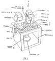
- Fig. 1 shows schematically one example of a microwave oven.
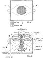
- Fig. 2 shows schematically some air flows in the oven of Fig. 1.
- Fig. 3 is a cross section of a hot jet airsteam surrounded by a sleeve of cooler air.
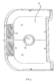
- Fig. 4 is an upward view of the roof of the oven of Fig. 1.
- Fig. 5 is a left side view of the roof of Fig. 4.
- Fig. 6 is a right side view of the roof of Fig. 4.
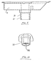
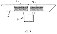
- Fig. 7 is a front view of the roof of Fig. 4.
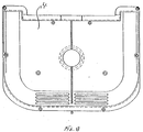
- Fig. 8 is a downwards view of the roof of Fig. 4.
- Fig. 9 is a rear view of the roof of Fig. 4.
- Fig. 10 is a fragmentary view corresponding to Fig. 4, and shows the discharge ends of a nozzle and a circumjacent sleeve.
- Fig. 11 is an upwards view of the discharge ends shown in Fig. 10.
- Fig. 12 is a schematic view of the nozzle of Fig. 10, and a heater and a fan unit.
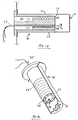
- Fig. 13 is a sectional view of one of example the nozzle of Fig. 12, showing a heater with a thermocouple temperature sensor.
- Fig. 14 is fragmentary view corresponding to Fig. 13.
- Fig. 15 shows one example of a temperature control circuit comprising the thermocouple sensor of Fig. 13, to control heating provided by the heating element.
- Fig. 16 shows one example of a fan monitor control circuit, to control the fan unit of Fig. 12.
- a microwave oven 1 has a thermal cavity 2 (i.e. the oven cavity) for receiving microwave energy from two magnetrons 3 mounted above the roof 4 of cavity 2, via two waveguides 5 and two stirrers 6 having rotatable vanes 7 comprising mica. Rotation of the vanes 7 is provided by an airflow B described later below. Vanes 7 enable an even distribution of microwave energy to pass downwards through roof 4 and into oven cavity 2.
- Oven 1 has two outlet vents 8 (Figs. 1,2) for allowing air from cavity 2 to pass outwards, e.g. to the ambient atmosphere.
- Roof 4 is transparent to microwave energy and may comprise any suitable material(s), e.g. polymeric materials, for instance flame retardant polypropylene(s).
- roof 4 is electrically insulating.
- Air portion A passes to nozzle 21 described later below.
- Air portion B provides cooling of the magnetrons, and then passes via stirrers 6 (and rotates their vanes 7) and into an annular passage between nozzle 21 and a circumjacent sleeve 31 described later below.
- Air portion C passes to outlet slots 9 (Fig. 4) in the front portion of the underneath of roof 4, and thence into oven cavity 2 and towards the inwardly facing surface of door 10 (Fig. 3) of cavity 2, such that the flow rate and/or temperature of this air will prevent or resist formation of condensation on the inwardly facing surface of door 10 (Fig. 3) of cavity 2.
- Air portion C is optional. It may be provided by air portion B after that portion has cooled the magnetrons.
- Nozzle 21 and fan unit 24 comprise one example of at least one said first supply means, for supplying hot air to the thermal cavity 2.
- Nozzle 21 (Fig. 11,12,13,14) includes a variable output electrical resistance heater 22 within a spaced apart circumjacent electrically conductive housing 23.
- Nozzle 21 comprises longitudinal ducts 25 for air (Fig. 14).
- Nozzle 21 receives portion A of air via fan unit 24, such that portion A may be heated, and then discharged via longitudinal ducts 25 and circular outlet nozzle holes 26 (Fig. 14) comprised by the discharge end of housing 23.
- Ducts 25 and holes 26 have sizes to prevent or resist transmission therethrough of microwave energy.
- Housing 23 may comprise any suitable material(s), e.g. metal(s) or metal(s) coated onto ceramic(s). Housing 23 is cylindrical.
- thermocouple 27 extends longitudinally through heater 22, so that the sensor tip 28 of the thermocouple protrudes from the heater and into the heated air being discharged therefrom.
- the thermocouple outputs at least one signal for enabling temperature control of the heater 22, and hence control of temperature of the discharging hot air.
- the at least one signal can be processed by the heating control circuit shown in Fig. 15. It is possible for the heater 22 to be switched to half wave rectified mains current rather than completely off, whereby thermal shock to the heater is reduced and its life is extended.
- Fig. 16 shows a fan monitor control circuit for fan unit 24 of Fig. 12.
- This circuit can prevent the heater 22 from being energised if there is a fault with the fan unit, and is a window comparator that may be used to see whether or not the fan unit is operating correctly.
- the fan monitor control circuit prevents the heater from burning out due to insufficent air flow.
- Some examples of providing control of operation(s) are: controlling nozzle temperature by varying the fan speed of the fan unit; measuring temperature by monitoring the heating element resistance; and monitoring input voltages and/or currents, to control the input power to the heater.
- Sleeve 31 is one example of at least one said second supply means, for supplying cool air to the thermal cavity 2.
- Sleeve 31 is preferably electrically insulating, and may comprise any suitable material(s), e.g. polymeric materials (for instance polytetrafluoroethylenes, or ceramic materials).
- Relatively cool air B passes from the discharge end of sleeve 31 into the oven cavity 2, and downwards as a circumjacent column, jacket, mantle, or sleeve of cool air B relative to the discharged hot air portion A, at least a portion of the discharged cool air assisting in containing and/or directing (optionally to concentrate) at least a portion of the discharged hot air, so as to provide localisation of at least a portion of the discharged hot air, and to prevent or reduce heat reaching at least a portion of the boundary (e.g. the door and/or sides) of the oven cavity 2, this heat being provided by the discharged hot air portion A.
- the boundary e.g. the door and/or sides
- the cool air B enables at least one of the problems of texture, preheating, and heat retention (described earlier above) to be prevented or reduced, e.g. in respect of food items that are pastry(s), etc.
- the above mentioned discharged cool air will provide localisation (e.g. to concentrate) of at least a portion of the hot air in the thermal cavity 2 (i.e. the oven cavity), and optionally prevent or reduce heat reaching at least a portion of the boundary of the cavity.
- the oven described with reference to the drawings may comprise any suitable control means, and/or at least one cooler means (not shown), as described earlier above.
Description
Claims (11)
- Apparatus having a microwave oven cavity (1), said apparatus comprising:at least one microwave means (3) for providing microwave energy in said microwave oven cavity;at least one first supply means (21) for downwardly supplying in said microwave oven cavity a column (A) of hot air, downwardly directed to the region of an item (F) to be heated by said microwave energy in said cavity; and wherein said apparatus is characterised by: at least one second supply means (31), for downwardly supplying in said cavity a downwardly directed hollow column (B) of cool air relative to said downwardly directed column of hot air;said at least one second supply means being sufficiently surrounding and spaced apart from said at least one first supply means such that said downwardly directed hollow column of cool air will be circumjacent said downwardly directed column of hot air so that said column of hot air is localised in said region by means of said hollow column of downwardly directed cool air.
- Apparatus as claimed in claim 1, wherein said at least one microwave means comprises at least one magnetron (3).
- Apparatus as claimed in claim 1 or 2, wherein said at least one first supply means comprises at least one nozzle means (21) for supplying said downwardly directed column of hot air.
- Apparatus as claimed in any one of claims 1 to 3, wherein said at least one nozzle means comprises discharge outlets (26) for supplying jet streams of said hot air such that said downwardly directed column (A) of hot air comprises jet streams of said hot air.
- Apparatus as claimed in any one of claims 1 to 4, wherein said at least one first supply means comprises at least one heater means (22) for heating air to be comprised by said column of hot air.
- Apparatus as claimed in claim 5, wherein said at least one heater means comprises at least one electrical resistance heater (22).
- Apparatus as claimed in any one of claims 1 to 6, wherein said at least one second supply means comprises at least one sleeve means (31) surrounding and spaced apart from said at least one said first supply means (21) such that said downwardly directed hollow column (B) of cool air is circumjacent said downwardly directed column (A) of hot air.
- Apparatus as claimed in any one of claims 1 to 7, comprising at least one outlet vent (8) for venting air from said region.
- Apparatus as claimed in any one of claims 1 to 8, comprising at least one control means (27) for controlling said apparatus.
- Apparatus as claimed in claim 9, comprising at least one temperature control means (27) for controlling temperature of said hot air being supplied from said at least one first supply means.
- A method of heating, comprising utilising apparatus as claimed in any one of claims 1 to 10 so as to heat said item (F).
Applications Claiming Priority (2)
| Application Number | Priority Date | Filing Date | Title |
|---|---|---|---|
| GB939313171A GB9313171D0 (en) | 1993-06-25 | 1993-06-25 | Microwave heating |
| GB9313171 | 1993-06-25 |
Publications (3)
| Publication Number | Publication Date |
|---|---|
| EP0631459A2 EP0631459A2 (en) | 1994-12-28 |
| EP0631459A3 EP0631459A3 (en) | 1995-02-22 |
| EP0631459B1 true EP0631459B1 (en) | 1998-09-23 |
Family
ID=10737816
Family Applications (1)
| Application Number | Title | Priority Date | Filing Date |
|---|---|---|---|
| EP94304454A Expired - Lifetime EP0631459B1 (en) | 1993-06-25 | 1994-06-20 | Hot Air-Microwave oven |
Country Status (4)
| Country | Link |
|---|---|
| US (1) | US5483044A (en) |
| EP (1) | EP0631459B1 (en) |
| DE (1) | DE69413457T2 (en) |
| GB (2) | GB9313171D0 (en) |
Cited By (1)
| Publication number | Priority date | Publication date | Assignee | Title |
|---|---|---|---|---|
| EP1542511B2 (en) † | 2003-12-10 | 2011-09-21 | Samsung Electronics Co., Ltd. | Method of controlling a cooking apparatus |
Families Citing this family (31)
| Publication number | Priority date | Publication date | Assignee | Title |
|---|---|---|---|---|
| KR0119927Y1 (en) * | 1995-06-29 | 1998-08-01 | 김광호 | Microwave oven |
| US5780815A (en) * | 1996-05-17 | 1998-07-14 | Air Fry, Inc. | Oil-free fryer, food cooker |
| US5994672A (en) * | 1996-05-17 | 1999-11-30 | Air Fry, Inc. | Oil-free fryer, food cooker |
| US7092988B1 (en) | 1997-05-27 | 2006-08-15 | Jeffrey Bogatin | Rapid cooking oven with broadband communication capability to increase ease of use |
| US6140626A (en) * | 1998-04-23 | 2000-10-31 | Turbochef Technologies, Inc. | System for rapid air temperature modification in a recycling oven |
| CA2209321A1 (en) * | 1997-06-30 | 1998-12-30 | Ana Ferraro | Microwave oven |
| FR2772208B1 (en) * | 1997-12-05 | 2000-02-25 | Sgs Thomson Microelectronics | DEVICE FOR SUPPLYING A NON-LINEAR LOAD, IN PARTICULAR A MAGNETRON OF A MICROWAVE OVEN |
| FR2773872B1 (en) * | 1998-01-22 | 2000-03-31 | Sgs Thomson Microelectronics | METHOD FOR CONTROLLING AN ELECTRIC OVEN AND DEVICE FOR IMPLEMENTING IT |
| US6217918B1 (en) | 1998-05-08 | 2001-04-17 | Bestfoods | Microwavable pasta in a bowl |
| US6175105B1 (en) | 1998-10-02 | 2001-01-16 | Bestfoods | Container for microwave cooking of food products containing liquids |
| USD426427S (en) * | 1998-10-02 | 2000-06-13 | Bestfoods | Bowl |
| GB2341677B (en) * | 1999-11-20 | 2000-12-27 | Merrychef Ltd | Ovens with catalytic converters |
| KR20010065013A (en) * | 1999-12-20 | 2001-07-11 | 구자홍 | Convection device for microwave oven |
| DE10049847B4 (en) * | 2000-04-19 | 2005-12-01 | Lg Electronics Inc. | microwave oven |
| US8224892B2 (en) * | 2000-04-28 | 2012-07-17 | Turbochef Technologies, Inc. | Rapid cooking oven with broadband communication capability to increase ease of use |
| MX2007007104A (en) | 2004-12-14 | 2007-11-16 | Enodis Corp | Impingement/ convection/ microwave oven and method. |
| US8022341B2 (en) | 2007-05-15 | 2011-09-20 | Appliance Scientific, Inc. | High-speed cooking oven with optimized cooking efficiency |
| US8129665B2 (en) * | 2007-05-15 | 2012-03-06 | Appliance Scientific, Inc. | Apparatus and method for heating or cooling an object using a fluid |
| US7435931B1 (en) * | 2007-05-15 | 2008-10-14 | Appliance Scientific, Inc. | High-speed cooking oven with optimized cooking efficiency |
| US8134102B2 (en) * | 2007-05-15 | 2012-03-13 | Appliance Scientific, Inc. | High-speed cooking oven with cooking support |
| US8455797B2 (en) * | 2007-05-15 | 2013-06-04 | Appliance Scientific, Inc. | High-speed cooking oven with optimized cooking efficiency |
| US8026463B2 (en) * | 2007-05-15 | 2011-09-27 | Appliance Scientific, Inc. | High-speed cooking oven with optimized cooking efficiency |
| WO2011140258A1 (en) * | 2010-05-04 | 2011-11-10 | Appliance Scientific, Inc. | Oven circulating heated air |
| US8759731B2 (en) | 2010-05-06 | 2014-06-24 | Appliance Scientific, Inc. | Plurality of accelerated cooking ovens with master-slave power assembly |
| EP3104667B1 (en) * | 2014-02-05 | 2019-10-02 | Panasonic Intellectual Property Management Co., Ltd. | Microwave heating device |
| US10088172B2 (en) | 2016-07-29 | 2018-10-02 | Alto-Shaam, Inc. | Oven using structured air |
| US10337745B2 (en) | 2015-06-08 | 2019-07-02 | Alto-Shaam, Inc. | Convection oven |
| US9879865B2 (en) | 2015-06-08 | 2018-01-30 | Alto-Shaam, Inc. | Cooking oven |
| US9677774B2 (en) | 2015-06-08 | 2017-06-13 | Alto-Shaam, Inc. | Multi-zone oven with variable cavity sizes |
| US10890336B2 (en) | 2015-06-08 | 2021-01-12 | Alto-Shaam, Inc. | Thermal management system for multizone oven |
| CN106900099B (en) * | 2017-02-28 | 2020-10-23 | 广东美的厨房电器制造有限公司 | Cooking device |
Family Cites Families (15)
| Publication number | Priority date | Publication date | Assignee | Title |
|---|---|---|---|---|
| US3692968A (en) * | 1970-04-06 | 1972-09-19 | Sanyo Electric Co | Electronic oven |
| US3878350A (en) * | 1971-07-15 | 1975-04-15 | Sharp Kk | Microwave cooking apparatus |
| US3884213A (en) * | 1973-03-30 | 1975-05-20 | Donald P Smith | Cooking apparatus |
| GB1463657A (en) * | 1973-04-24 | 1977-02-02 | Boc International Ltd | Microwave oven |
| US4409453A (en) * | 1976-05-19 | 1983-10-11 | Smith Donald P | Combined microwave and impingement heating apparatus |
| JPS56149531A (en) * | 1980-04-22 | 1981-11-19 | Sharp Corp | Hot-air circulation type cooker |
| JPS57188942A (en) * | 1981-05-18 | 1982-11-20 | Tatemi Sueshige | Cooking stove |
| US4591683A (en) * | 1982-07-17 | 1986-05-27 | Microwave Ovens Limited | Microwave ovens and methods of cooking food |
| JPS5923189U (en) * | 1982-08-04 | 1984-02-13 | シャープ株式会社 | High frequency heating cooker |
| JPS63131931A (en) * | 1986-11-21 | 1988-06-03 | Matsushita Electric Works Ltd | Smoke disposal device for cooking |
| JPS63180021A (en) * | 1987-01-19 | 1988-07-25 | Toshio Tamaoka | Cooking table |
| WO1990008449A1 (en) * | 1989-01-12 | 1990-07-26 | Wolfgang Frech | Combined microwave, infrared and convection oven |
| JPH0320A (en) * | 1989-05-27 | 1991-01-07 | Dainichi Seisakusho:Kk | Gas roaster |
| US5166487A (en) * | 1989-12-15 | 1992-11-24 | Tecogen, Inc. | Cooking oven with convection and microwave heating |
| US5166484A (en) * | 1990-10-05 | 1992-11-24 | Astex/Gerling Laboratories, Inc. | Microwave system and method for curing rubber |
-
1993
- 1993-06-25 GB GB939313171A patent/GB9313171D0/en active Pending
-
1994
- 1994-06-17 US US08/261,547 patent/US5483044A/en not_active Expired - Lifetime
- 1994-06-20 DE DE69413457T patent/DE69413457T2/en not_active Expired - Lifetime
- 1994-06-20 EP EP94304454A patent/EP0631459B1/en not_active Expired - Lifetime
- 1994-06-20 GB GB9412338A patent/GB2279856B/en not_active Expired - Lifetime
Cited By (1)
| Publication number | Priority date | Publication date | Assignee | Title |
|---|---|---|---|---|
| EP1542511B2 (en) † | 2003-12-10 | 2011-09-21 | Samsung Electronics Co., Ltd. | Method of controlling a cooking apparatus |
Also Published As
| Publication number | Publication date |
|---|---|
| DE69413457T2 (en) | 1999-05-12 |
| GB9313171D0 (en) | 1993-08-11 |
| GB9412338D0 (en) | 1994-08-10 |
| US5483044A (en) | 1996-01-09 |
| DE69413457D1 (en) | 1998-10-29 |
| GB2279856B (en) | 1997-03-05 |
| GB2279856A (en) | 1995-01-11 |
| EP0631459A2 (en) | 1994-12-28 |
| EP0631459A3 (en) | 1995-02-22 |
Similar Documents
| Publication | Publication Date | Title |
|---|---|---|
| EP0631459B1 (en) | Hot Air-Microwave oven | |
| US11546976B2 (en) | Cooking apparatus and control method thereof | |
| CA2327099C (en) | Residential oven with convectional and microwave heating | |
| US6943321B2 (en) | Convection oven with forced airflow circulation zones | |
| EP0023827B1 (en) | Cooking appliance of hot air circulating type | |
| US9351495B2 (en) | Air fryer | |
| US5558793A (en) | Quick-cooking oven | |
| EP1431667B1 (en) | Electric oven | |
| US6140626A (en) | System for rapid air temperature modification in a recycling oven | |
| US20070221070A1 (en) | Cooker and Cooking Method | |
| US20070137633A1 (en) | Conveyor oven | |
| JP2006329623A (en) | Oven for cooking food, and control method therefor | |
| US6005235A (en) | Cooling apparatus for a microwave oven having lighting lamps | |
| KR20030074709A (en) | Thermal/convection oven including halogen lamps | |
| JP2005147604A (en) | High frequency heating cooking device, and cooking method using the device | |
| CA1152573A (en) | Combination microwave/forced convection oven with a microwave transparent container | |
| JP2006275390A (en) | Cooking apparatus | |
| JP2002048344A (en) | Heating cooking apparatus | |
| KR100339950B1 (en) | Method for controlling a microwave oven, microwave oven and its use for cooking or heating food in accordance with the method | |
| JPS6131777B2 (en) | ||
| JP2012112572A (en) | Heating cooker | |
| JPH09112908A (en) | Heater | |
| EP0830064B1 (en) | An oven for the preparation of food | |
| JPH06272864A (en) | High frequency wave heating cooking apparatus | |
| JP3773466B2 (en) | Hot air generator |
Legal Events
| Date | Code | Title | Description |
|---|---|---|---|
| PUAI | Public reference made under article 153(3) epc to a published international application that has entered the european phase |
Free format text: ORIGINAL CODE: 0009012 |
|
| AK | Designated contracting states |
Kind code of ref document: A2 Designated state(s): AT BE CH DE DK ES FR GB GR IE IT LI LU MC NL PT SE |
|
| RAX | Requested extension states of the european patent have changed |
Free format text: SI |
|
| PUAL | Search report despatched |
Free format text: ORIGINAL CODE: 0009013 |
|
| AK | Designated contracting states |
Kind code of ref document: A3 Designated state(s): AT BE CH DE DK ES FR GB GR IE IT LI LU MC NL PT SE |
|
| RBV | Designated contracting states (corrected) |
Designated state(s): DE FR IT |
|
| 17P | Request for examination filed |
Effective date: 19950706 |
|
| 17Q | First examination report despatched |
Effective date: 19961217 |
|
| GRAG | Despatch of communication of intention to grant |
Free format text: ORIGINAL CODE: EPIDOS AGRA |
|
| GRAG | Despatch of communication of intention to grant |
Free format text: ORIGINAL CODE: EPIDOS AGRA |
|
| GRAH | Despatch of communication of intention to grant a patent |
Free format text: ORIGINAL CODE: EPIDOS IGRA |
|
| GRAH | Despatch of communication of intention to grant a patent |
Free format text: ORIGINAL CODE: EPIDOS IGRA |
|
| GRAA | (expected) grant |
Free format text: ORIGINAL CODE: 0009210 |
|
| AK | Designated contracting states |
Kind code of ref document: B1 Designated state(s): DE FR IT |
|
| REF | Corresponds to: |
Ref document number: 69413457 Country of ref document: DE Date of ref document: 19981029 |
|
| ET | Fr: translation filed | ||
| PLBE | No opposition filed within time limit |
Free format text: ORIGINAL CODE: 0009261 |
|
| STAA | Information on the status of an ep patent application or granted ep patent |
Free format text: STATUS: NO OPPOSITION FILED WITHIN TIME LIMIT |
|
| 26N | No opposition filed | ||
| PGFP | Annual fee paid to national office [announced via postgrant information from national office to epo] |
Ref country code: IT Payment date: 20110613 Year of fee payment: 18 |
|
| PG25 | Lapsed in a contracting state [announced via postgrant information from national office to epo] |
Ref country code: IT Free format text: LAPSE BECAUSE OF NON-PAYMENT OF DUE FEES Effective date: 20120620 |
|
| PGFP | Annual fee paid to national office [announced via postgrant information from national office to epo] |
Ref country code: DE Payment date: 20130627 Year of fee payment: 20 |
|
| PGFP | Annual fee paid to national office [announced via postgrant information from national office to epo] |
Ref country code: FR Payment date: 20130702 Year of fee payment: 20 |
|
| REG | Reference to a national code |
Ref country code: DE Ref legal event code: R071 Ref document number: 69413457 Country of ref document: DE |
|
| PG25 | Lapsed in a contracting state [announced via postgrant information from national office to epo] |
Ref country code: DE Free format text: LAPSE BECAUSE OF EXPIRATION OF PROTECTION Effective date: 20140621 |