EP0631109B1 - Passive image sensor navigation system - Google Patents
Passive image sensor navigation system Download PDFInfo
- Publication number
- EP0631109B1 EP0631109B1 EP94107119A EP94107119A EP0631109B1 EP 0631109 B1 EP0631109 B1 EP 0631109B1 EP 94107119 A EP94107119 A EP 94107119A EP 94107119 A EP94107119 A EP 94107119A EP 0631109 B1 EP0631109 B1 EP 0631109B1
- Authority
- EP
- European Patent Office
- Prior art keywords
- data
- velocity
- processor
- sensor
- vehicle
- Prior art date
- Legal status (The legal status is an assumption and is not a legal conclusion. Google has not performed a legal analysis and makes no representation as to the accuracy of the status listed.)
- Expired - Lifetime
Links
- 230000003287 optical effect Effects 0.000 claims description 37
- 238000004364 calculation method Methods 0.000 claims description 13
- 239000013598 vector Substances 0.000 claims description 9
- 230000010354 integration Effects 0.000 claims description 7
- 238000003384 imaging method Methods 0.000 claims description 6
- 238000000034 method Methods 0.000 description 6
- 238000010586 diagram Methods 0.000 description 5
- 238000004458 analytical method Methods 0.000 description 4
- 239000011159 matrix material Substances 0.000 description 2
- 230000001133 acceleration Effects 0.000 description 1
- 238000001514 detection method Methods 0.000 description 1
- 238000006073 displacement reaction Methods 0.000 description 1
- 230000000694 effects Effects 0.000 description 1
- 238000005259 measurement Methods 0.000 description 1
- 238000007619 statistical method Methods 0.000 description 1
- 230000009466 transformation Effects 0.000 description 1
Images


Classifications
-
- G—PHYSICS
- G01—MEASURING; TESTING
- G01C—MEASURING DISTANCES, LEVELS OR BEARINGS; SURVEYING; NAVIGATION; GYROSCOPIC INSTRUMENTS; PHOTOGRAMMETRY OR VIDEOGRAMMETRY
- G01C21/00—Navigation; Navigational instruments not provided for in groups G01C1/00 - G01C19/00
- G01C21/20—Instruments for performing navigational calculations
Definitions
- the invention relates to a system of navigation for use in a mobile vehicle as set forth in the preamble of claim 1.
- EP-A 436 213 concerns a system incorporating inertial sensor information into optical flow computations to detect obstacles and to provide alternative navigational paths free from obstacles.
- This known system is a maximally passive obstacle detection system that makes selective use of an active sensor.
- GB-A 2 212 687 relates to an aircraft navigation system that uses an infra-red scanner to provide an image of the ground, and a laser doppler system to measure the speed of the aircraft relative to the ground.
- the present invention pertains to aircraft guidance systems for mobile vehicles, primarily aircraft, that utilize image data available from onboard image sensors.
- Many aircraft applications involve the use of a passive imaging sensor in order to accomplish the mission objectives.
- image data that pertains to the primary use of the imager
- the fact that the imager is carried onboard can be exploited to aid in navigating the aircraft.
- INS inertial navigation system
- INS systems are extremely costly due to their mechanical and electronic complexity, and they impose a payload penalty on the aircraft in terms of size, weight, and power.
- the presence onboard of an imaging sensor provides image data that can be processed to derive information about the aircraft attitude and velocity, which can be further processed to derive the aircraft position in a defined reference frame.
- a system of navigation that derives the velocity vector without the use of an INS.
- the system uses the motion of the scene viewed by the imager in the imager's field of view (FOV) in order to calculate the aircraft velocity.
- the motion of the image points in the FOV due to the motion of the aircraft is referred to as the optical flow. It is well known that the optical flow from a single imager can provide the velocity components only to within a global scale factor. Accordingly, there is provided input data from a second sensor that enables calculation of the scale factor such that the velocity magnitude and direction is known on an absolute scale.
- This second sensor may also be part of the typical aircraft sensor suite, for example but not limited to such things as altimeter, airspeed indicator, engine throttle readout, engine thrust readout, autopilot accelerometers and gyroscopes, or any other sensor that provides data that can be used to estimate any component of the aircraft velocity.
- a further object of the present invention is to provide a navigation system for aircraft that have no inertial navigation system or other navigation system.
- Yet another object of the present invention is to provide a navigation system that requires no additional hardware beyond the existing hardware on board the aircraft.
- Another object of the present invention is to provide a navigation system that works off of data already available in the aircraft system.
- a further object of the invention is to provide a means to recover the global scale factor for the optical flow velocity equation using a secondary sensor.
- the motion of an image sensor in the scene environment will produce an apparent motion of the elements of the scene on the focal plane.
- This motion is referred to as optical flow and it is analytically predictable from the motion of the imager V , the structure of the environment, and the imager characteristics.
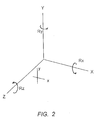
- FIG. 2 we define the coordinate system with origin at the imager focal plane, the positive Z axis defines the line of sight (LOS) of the imager, the positive X axis points left when viewed from the focal plane and the positive Y axis points up to form a right handed coordinate system.
- the scene environment is described by points which have their position vector X [ X Y Z ].
- the imager velocity is defined by the translation vector V [ Vx Vy Vz ] and the angular velocity vector R [ Rx Ry Rz ].
- the primary objective of the passive image sensor navigation system which is functionally diagrammed in FIG. 1 is to provide position information for aircraft which carry passive imagers.
- This primary object is implemented by taking time sequential image frames from the image sensor 1 and imager orientation information from the gimbaled platform on which it is mounted 2 and processing the data in order to derive the motion of the image (its optical flow) on the focal plane 3 .
- Data from the secondary sensor 4 is transformed to the coordinate system of the optical flow processor 5 and used to calculate the global scale factor 6 .
- the scale factor resolution and the optical flow data are used to calculate the aircraft velocity V in the velocity calculation module 7 .
- the aircraft velocity is then integrated over time 8 to provide the displacement X 9 from the original position X0.
- FIG. 3 functionally diagrams the new solution of time-delayed modified difference field, which is an advance in the state of the art in the following way:
- the effect of having two cameras is produced by recording the velocity field v1 at time t1 and then letting the aircraft move to a new position at time t2.
- V1 and V2 are now two aircraft velocities, V1 and V2 , at times t1 and t2. These two aircraft velocities produce velocity flow fields v1 and v2 on the imager 1 which are calculated in the optical flow processor 3 and passed to the modified difference field processor 10 .
- the secondary sensor 4 measures or estimates the velocity of the aircraft in its own coordinate frame which is then passed to the coordinate transform processor 5 which converts the data to V1 and V2 in the suitable coordinate system; this velocity data is passed to the modified difference field processor 10 .
- the modified difference field processor 10 also receives the imager gimbal position data from the gimbal platform 2 .
- the dV difference in velocities needed to solve the modified difference flow field equation can be provided by the aircraft autopilot subsystem.
- an autopilot will provide orientation and acceleration information about the aircraft that is normally used to stabilize the flight path.
- the bias and drift errors are much too large for this velocity measurement to be useful over a long period of time in order to navigate.
- the accuracy over a short time period between t1 and t2 is sufficient to provide the dV data to the modified difference flow processor.
- This technique requires that the difference in velocity in the Z direction (dVz) be nonzero. This can be accomplished by maneuvering the aircraft and the gimbal between times t1 and t2. Notice also that this technique does not require any assumptions about the scene environment because Z is determined independently at each point (x,y) in image space.
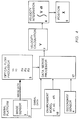
- Another technique of passive navigation that is part of this invention as illustrated in the functional block diagram in FIG. 4 is to combine the secondary sensor data with an assumption about the structure of the environment in order to resolve the ambiguity of the global scale factor that is contained in the optical flow field.
- the imager 1 mounted on a gimbal platform 2 .
- the image data from the imager is passed to the optical flow processor 3 which calculates the optical flow field at points in the image plane v (x,y).
- the secondary sensor 4 senses data about the aircraft or its environment.
- an environment model 16 that describes some assumptions about the structure of the scene environment.
- the data merge processor 17 which also receives data from the secondary sensor 4 , the optical flow processor 3 , and the gimbal platform 2 .
- the data merge processor uses the optical flow data to solve for the aircraft velocity to within the ambiguity of the global scale factor, and then resolves the global scale factor using the data from the secondary sensor with the assumptions contained in the environment model in order to estimate or solve for V 7 . Then as previously described V is then integrated over time in the velocity integration processor 8 in order to calculate the position X 9 relative to the initial point.
- N N
- the data merge processor 17 and the velocity calculation 7 can solve the equations.
- a numerical analysis technique such as minimum least square can be used to calculate V .
- V is then integrated over time in the velocity integration processor 8 in order to calculate the position X 9 relative to the initial point.
- This invention provides certain advantages with respect to the current state of the art because the necessity for a second imager has been removed. Consequently, the mechanical apparatus previously required in order to provide for a nonzero relative velocity is also eliminated.
- Eliminating the second camera reduces the size, weight, power, and complexity of the passive navigation system.
- the solution for Z(x,y) is proportional to dVz
- another advantage of this invention over the current state of the art is that the accuracy of the solution is not limited by the relative velocity obtainable between the two cameras with a mechanical apparatus, since this is determined by the aircraft velocity and autopilot system.
- This invention provides other advantages over the current state of the art in that it provides a method to integrate data already available to the aircraft platform in order to determine position without requiring either additional sensors or increased performance in the sensor systems installed.
Landscapes
- Engineering & Computer Science (AREA)
- Radar, Positioning & Navigation (AREA)
- Remote Sensing (AREA)
- Automation & Control Theory (AREA)
- Physics & Mathematics (AREA)
- General Physics & Mathematics (AREA)
- Navigation (AREA)
- Control Of Position, Course, Altitude, Or Attitude Of Moving Bodies (AREA)
- Radar Systems Or Details Thereof (AREA)
- Position Fixing By Use Of Radio Waves (AREA)
Description
- The invention relates to a system of navigation for use in a mobile vehicle as set forth in the preamble of
claim 1. - Such a system is described in Proceedings of the 12th Canadian Symposium on Remote Sensing IGARSS 89, Remote Sensing: "An Economic Tool for the Nineties", by S. Negahdaripour, July 10 - 14, 1989, Vancouver, Canada, Vol. 3, pp. 1264 - 1266. In this article, monocular motion stereo navigation schemes are described which are based on optical flow determination.
- EP-A 436 213 concerns a system incorporating inertial sensor information into optical flow computations to detect obstacles and to provide alternative navigational paths free from obstacles. This known system is a maximally passive obstacle detection system that makes selective use of an active sensor.
- GB-A 2 212 687 relates to an aircraft navigation system that uses an infra-red scanner to provide an image of the ground, and a laser doppler system to measure the speed of the aircraft relative to the ground.
- The present invention, the most essential features of which are described in
claim 1, pertains to aircraft guidance systems for mobile vehicles, primarily aircraft, that utilize image data available from onboard image sensors. Many aircraft applications involve the use of a passive imaging sensor in order to accomplish the mission objectives. In addition to providing image data that pertains to the primary use of the imager, the fact that the imager is carried onboard can be exploited to aid in navigating the aircraft. Generally aircraft navigation requires an inertial navigation system (INS) in order to determine its position with respect to some inertial reference frame. INS systems are extremely costly due to their mechanical and electronic complexity, and they impose a payload penalty on the aircraft in terms of size, weight, and power. - The presence onboard of an imaging sensor provides image data that can be processed to derive information about the aircraft attitude and velocity, which can be further processed to derive the aircraft position in a defined reference frame.
- According to the invention, there is provided a system of navigation that derives the velocity vector without the use of an INS. The system uses the motion of the scene viewed by the imager in the imager's field of view (FOV) in order to calculate the aircraft velocity. The motion of the image points in the FOV due to the motion of the aircraft is referred to as the optical flow. It is well known that the optical flow from a single imager can provide the velocity components only to within a global scale factor. Accordingly, there is provided input data from a second sensor that enables calculation of the scale factor such that the velocity magnitude and direction is known on an absolute scale. This second sensor may also be part of the typical aircraft sensor suite, for example but not limited to such things as altimeter, airspeed indicator, engine throttle readout, engine thrust readout, autopilot accelerometers and gyroscopes, or any other sensor that provides data that can be used to estimate any component of the aircraft velocity.
- It is therefore the object of this invention to provide a navigation system for aircraft using the optical flow from an imager on board the aircraft.
- A further object of the present invention is to provide a navigation system for aircraft that have no inertial navigation system or other navigation system.
- Yet another object of the present invention is to provide a navigation system that requires no additional hardware beyond the existing hardware on board the aircraft.
- Another object of the present invention is to provide a navigation system that works off of data already available in the aircraft system.
- A further object of the invention is to provide a means to recover the global scale factor for the optical flow velocity equation using a secondary sensor.
- Other objects and many of the attendant advantages of the present invention will be readily apparent as the invention becomes better understood by reference to the following detailed description with the appended claims, when considered in conjunction with the accompanying drawings, wherein:
- FIG. 1 is a functional block diagram of the passive
navigation system according to the present invention,
which includes the following items:
- 1 the image sensor;
- 2 gimbal platform on which the image sensor is mounted;
- 3 optical flow processor;
- 4 secondary sensor;
- 5 coordinate transform processor;
- 6 scale factor resolution module;
- 7 velocity calculation module;
- 8 velocity integration module;
- 9 position calculation module.
- FIG. 2 schematically defines the coordinate system in relation to the image sensor.
- FIG. 3 is a functional block diagram of the passive
navigation system using difference of optical flow, and
includes the following items:
- 1 the image sensor;
- 2 gimbal platform on which the image sensor is mounted;
- 3 optical flow processor;
- 4 secondary sensor;
- 5 coordinate transform processor;
- 10 modified difference field processor;
- 11 data buffer to store the Z(x,y) values;
- 12 processor used to invert optical flow equation;
- 13 data buffer to store the velocity values in the imager coordinates;
- 14 aircraft navigation coordinate transform processor;
- 15 data buffer to store the velocity values in the aircraft navigation coordinates;
- 8 velocity integration module;
- 9 position calculation module.
- FIG. 4 is a functional block diagram of the passive
navigation system using an environment model, and
includes the following items:
- 1 the image sensor;
- 2 gimbal platform on which the image sensor is mounted;
- 3 optical flow processor;
- 4 secondary sensor;
- 16 environment model;
- 17 data merge processor;
- 7 velocity calculation module;
- 8 velocity integration module;
- 9 position calculation module.
-
- It is well known that the motion of an image sensor in the scene environment will produce an apparent motion of the elements of the scene on the focal plane. This motion is referred to as optical flow and it is analytically predictable from the motion of the imager V, the structure of the environment, and the imager characteristics. Referring now to FIG. 2 we define the coordinate system with origin at the imager focal plane, the positive Z axis defines the line of sight (LOS) of the imager, the positive X axis points left when viewed from the focal plane and the positive Y axis points up to form a right handed coordinate system. In this coordinate system the scene environment is described by points which have their position vector X [ X Y Z ]. The corresponding projection of a point at X in environment space has coordinates x [ x y ] on the focal plane where the x and y values of a point at (X,Y,Z) are given by projection
The imager velocity is defined by the translation vector V [ Vx Vy Vz ] and the angular velocity vector R [ Rx Ry Rz ]. The velocity V will define an optical flow on the focal plane as v = [ vx vy ] given by the formula
In a more general form the above equations can be written as The prior state of the art (Reference 1) uses two imagers in the following way to calculate the velocity V. (
Reference 2, published in 1992, indicates that the problem of a global scale factor is still in the prior state of the art.) If the two cameras are at some instant in time nearly coincident, the translation matrix [ T ] and the rotation matrix [ r ] will nearly identical for both cameras. Proceeding in time from that instant the two cameras move each with their own velocity V1 and V2 and rotational velocity R1 and R2. The difference in velocity between the two cameras is known and indeed controlled by the system, for example by moving the second camera along a sliding frame at a known rate. For each camera therefore there is a velocity flow field v1 and v2. The difference in velocities of the two cameras is dV and dR where - The primary objective of the passive image sensor navigation system according to the present invention which is functionally diagrammed in FIG. 1 is to provide position information for aircraft which carry passive imagers. This primary object is implemented by taking time sequential image frames from the
image sensor 1 and imager orientation information from the gimbaled platform on which it is mounted 2 and processing the data in order to derive the motion of the image (its optical flow) on thefocal plane 3. Data from thesecondary sensor 4 is transformed to the coordinate system of theoptical flow processor 5 and used to calculate theglobal scale factor 6. The scale factor resolution and the optical flow data are used to calculate the aircraft velocity V in thevelocity calculation module 7. The aircraft velocity is then integrated overtime 8 to provide thedisplacement X 9 from the original position X0. - Referring now to FIG. 3 which functionally diagrams the new solution of time-delayed modified difference field, which is an advance in the state of the art in the following way: Instead of using two cameras and a mechanical apparatus to create a known difference in velocities dV, the effect of having two cameras is produced by recording the velocity field v1 at time t1 and then letting the aircraft move to a new position at time t2. There are now two aircraft velocities, V1 and V2, at times t1 and t2. These two aircraft velocities produce velocity flow fields v1 and v2 on the
imager 1 which are calculated in theoptical flow processor 3 and passed to the modifieddifference field processor 10. Simultaneously thesecondary sensor 4 measures or estimates the velocity of the aircraft in its own coordinate frame which is then passed to the coordinatetransform processor 5 which converts the data to V1 and V2 in the suitable coordinate system; this velocity data is passed to the modifieddifference field processor 10. The modifieddifference field processor 10 also receives the imager gimbal position data from thegimbal platform 2. The modified difference field processor implements the equation listed above:flow equation processor 12 which uses the optical flow equationV 13 is then transformed to the suitable coordinate system by the aircraft navigation coordinate transform processor 14 in order to produce V 15, which as previously described is then integrated over time in thevelocity integration processor 8 in order to calculate theposition X 9 relative to the initial point. - As an example to illustrate better the functioning of the invention, but not limited to only this example, we can suppose that the dV difference in velocities needed to solve the modified difference flow field equation can be provided by the aircraft autopilot subsystem. Typically an autopilot will provide orientation and acceleration information about the aircraft that is normally used to stabilize the flight path. The bias and drift errors are much too large for this velocity measurement to be useful over a long period of time in order to navigate. However, the accuracy over a short time period between t1 and t2 is sufficient to provide the dV data to the modified difference flow processor. This technique requires that the difference in velocity in the Z direction (dVz) be nonzero. This can be accomplished by maneuvering the aircraft and the gimbal between times t1 and t2. Notice also that this technique does not require any assumptions about the scene environment because Z is determined independently at each point (x,y) in image space.
- Another technique of passive navigation that is part of this invention as illustrated in the functional block diagram in FIG. 4 is to combine the secondary sensor data with an assumption about the structure of the environment in order to resolve the ambiguity of the global scale factor that is contained in the optical flow field. Referring to FIG. 4 there is as presented previously the
imager 1 mounted on agimbal platform 2. The image data from the imager is passed to theoptical flow processor 3 which calculates the optical flow field at points in the image plane v(x,y). At the same time thesecondary sensor 4 senses data about the aircraft or its environment. There is incorporated in the invention anenvironment model 16 that describes some assumptions about the structure of the scene environment. These assumptions are used in the data mergeprocessor 17 which also receives data from thesecondary sensor 4, theoptical flow processor 3, and thegimbal platform 2. The data merge processor uses the optical flow data to solve for the aircraft velocity to within the ambiguity of the global scale factor, and then resolves the global scale factor using the data from the secondary sensor with the assumptions contained in the environment model in order to estimate or solve forV 7. Then as previously described V is then integrated over time in thevelocity integration processor 8 in order to calculate theposition X 9 relative to the initial point. - In order to better illustrate the functioning of the invention there is presented an example that is illustrative but not exhaustive in the application of the invention. We take the assumption of an environment model of a plane described by the equation of a plane,
optical flow processor 3. The environment parameters (b,c) are determined as above by (H,d) and the parameter a is defined to be zero. The depression angle d can be measured from the gimbal platform data and the height H is unknown. This is an illustrative but not exhaustive example of what thesecondary sensor 4 could be. In this case it is an altimeter that measures the actual height above ground, H, which is analogous to the distance from the plane. Thus there is a secondary data parameter that resolves the global scale factor in the optical flow equation. - Expanding the above equation we get for every point (i,j) with image plane coordinates (x,y) the equations
processor 17 and thevelocity calculation 7 can solve the equations. As an example, in order to reduce errors in the estimation, a numerical analysis technique such as minimum least square can be used to calculate V. Then as previously described V is then integrated over time in thevelocity integration processor 8 in order to calculate theposition X 9 relative to the initial point. - This invention provides certain advantages with respect to the current state of the art because the necessity for a second imager has been removed. Consequently, the mechanical apparatus previously required in order to provide for a nonzero relative velocity is also eliminated.
- Eliminating the second camera reduces the size, weight, power, and complexity of the passive navigation system. Noticing that the solution for Z(x,y) is proportional to dVz, another advantage of this invention over the current state of the art is that the accuracy of the solution is not limited by the relative velocity obtainable between the two cameras with a mechanical apparatus, since this is determined by the aircraft velocity and autopilot system.
- This invention provides other advantages over the current state of the art in that it provides a method to integrate data already available to the aircraft platform in order to determine position without requiring either additional sensors or increased performance in the sensor systems installed.
-
- (1) Dynamic Stereo: Passive Ranging to Moving Objects from Relative Flow Fields, Allen M. Waxman, Sarvajit S. Sinha, IEEE Transactions on Pattern Analysis and Machine Intelligence, Vol. PAMI-8, No. 4, July 1986, pp. 406 - 412.
- (2) Statistical Analysis of Inherent Ambiguities in Recovering 3-D Motion from a Noisy Flow Field, Gem-Sun Jason Young, Rama Chellappa, IEEE Transactions on Pattern Analysis and Machine Intelligence, Vol. PAMI-14, No. 10, October 1992, pp. 995 - 1013.
-
Claims (9)
- System of navigation for use in a mobile vehicle for providing vehicle guidance, based on optical flow determination, comprising an image sensor (1) carried on board of said vehicle and mounted on a gimbal platform (2), an optical flow processor (3) receiving image data from the image sensor (1), and a velocity calculation module (7) for calculating the velocity from the optical flow determined on the basis of the image data within a scale factor, characterized by a secondary sensor (4) for providing data indicative of any component of the vehicle velocity and means (6, 5, 10, 17) for calculating said scale factor on the basis of said data from said secondary sensor (4).
- System according to claim 1, characterised by the fact that said system is adapted to combine said data supplied by said imaging sensor (1) and said data supplied by said secondary sensor or sensors (4) on board the vehicle.
- System according to claim 2, characterised by the fact that said system is adapted to perform the combination of data to calculate the velocity vector of the vehicle and its three components with respect to a reference system rigidly fixed in the external environment.
- System according to claim 3, characterised in that said system is adapted to calculate the velocity vector by the steps ofretaining in memory data from said imaging sensor (1) and/or other data calculated from the image data, which data are acquired from said imaging sensor (1) at two different periods in time,combining said data with data supplied by said secondary sensor or sensors (4) on board the vehicle,combining said data in such a way as to determine the distance from the sensor (1) to points in the environment and therefore determine said velocity vector of the vehicle.
- System according to anyone of the preceding claims, characterised in that an output of said secondary sensor (4) is connected to a coordinate transform processor (5) that receives gimbal data from the imaging sensor (1).
- System according to claim 5, characterised in that the output ot the coordinate transform processor (5) is connected to a modified difference field processor (10).
- System according to claim 5, characterised in that a further output of the secondary sensor (4) is connected to a scale factor resolution module (6) receiving data from the coordinate transform processor (5), the output of the scale factor resolution module (6) being connected to the velocity calculation module (7).
- System according to anyone of the preceding claims, characterised by a data merge processor (17) receiving the gimbal data and data from the optical flow processor (3), from the secondary sensor (4) and from an environment model (16), the output of said data merge processor (17) being connected to said velocity calculation module (7).
- System according to anyone of the preceding claims, characterised by a velocity integration module (8) the output of which is connected to a position calculation module (9) whereas the input receives data from said velocity calculation module (7) or from the modified difference field processor (10) respectively.
Applications Claiming Priority (2)
| Application Number | Priority Date | Filing Date | Title |
|---|---|---|---|
| ITRM930368 | 1993-06-03 | ||
| ITRM930368A IT1261699B (en) | 1993-06-03 | 1993-06-03 | PASSIVE IMAGE SENSOR NAVIGATION SYSTEM. |
Publications (2)
| Publication Number | Publication Date |
|---|---|
| EP0631109A1 EP0631109A1 (en) | 1994-12-28 |
| EP0631109B1 true EP0631109B1 (en) | 2001-02-28 |
Family
ID=11401793
Family Applications (1)
| Application Number | Title | Priority Date | Filing Date |
|---|---|---|---|
| EP94107119A Expired - Lifetime EP0631109B1 (en) | 1993-06-03 | 1994-05-06 | Passive image sensor navigation system |
Country Status (3)
| Country | Link |
|---|---|
| EP (1) | EP0631109B1 (en) |
| DE (1) | DE69426738T2 (en) |
| IT (1) | IT1261699B (en) |
Cited By (1)
| Publication number | Priority date | Publication date | Assignee | Title |
|---|---|---|---|---|
| US7400950B2 (en) | 2002-09-23 | 2008-07-15 | Stefan Reich | Optical sensing system and system for stabilizing machine-controllable vehicles |
Families Citing this family (6)
| Publication number | Priority date | Publication date | Assignee | Title |
|---|---|---|---|---|
| DE10258545B4 (en) * | 2002-09-23 | 2008-01-24 | Stefan Reich | Method and system for stabilizing a translation motion size of a missile |
| ITTO20030197A1 (en) | 2003-03-14 | 2004-09-15 | Fiat Ricerche | ELECTRO-OPTICAL DEVICE ACTIVE FOR THE DETECTION OF |
| FR2927262B1 (en) * | 2008-02-13 | 2014-11-28 | Parrot | METHOD FOR CONTROLLING A ROTARY WING DRONE |
| DE102009060901A1 (en) | 2009-12-31 | 2011-07-07 | Deutsches Zentrum für Luft- und Raumfahrt e.V., 51147 | Landing aid device for vertical landing aircrafts, particularly helicopter, has image capturing unit for optical acquisition of spaces directly below a vertical landing aircraft, and evaluation unit |
| CN107390704B (en) * | 2017-07-28 | 2020-12-04 | 西安因诺航空科技有限公司 | IMU attitude compensation-based multi-rotor unmanned aerial vehicle optical flow hovering method |
| CN121353289B (en) * | 2025-12-19 | 2026-04-07 | 首都医科大学附属北京友谊医院 | Processing method and processing device for intestinal tract image of miniature intelligent terminal, storage medium and computer equipment |
Family Cites Families (5)
| Publication number | Priority date | Publication date | Assignee | Title |
|---|---|---|---|---|
| DE3047016A1 (en) * | 1980-12-13 | 1982-07-22 | Vereinigte Flugtechnische Werke Gmbh, 2800 Bremen | Aircraft surface navigation system - measures ground speed from comparison of image signals in successive image acquisition cycles |
| US4695959A (en) * | 1984-04-06 | 1987-09-22 | Honeywell Inc. | Passive range measurement apparatus and method |
| GB2212687A (en) | 1987-11-17 | 1989-07-26 | Gen Electric Co Plc | Vehicle navigation |
| US5128874A (en) * | 1990-01-02 | 1992-07-07 | Honeywell Inc. | Inertial navigation sensor integrated obstacle detection system |
| EP0436212A3 (en) | 1990-01-02 | 1992-07-29 | General Electric Company | Polyphenylene ether-polyepoxide compositions rapidly curable to flame retardant, solderable materials |
-
1993
- 1993-06-03 IT ITRM930368A patent/IT1261699B/en active IP Right Grant
-
1994
- 1994-05-06 EP EP94107119A patent/EP0631109B1/en not_active Expired - Lifetime
- 1994-05-06 DE DE69426738T patent/DE69426738T2/en not_active Expired - Fee Related
Cited By (1)
| Publication number | Priority date | Publication date | Assignee | Title |
|---|---|---|---|---|
| US7400950B2 (en) | 2002-09-23 | 2008-07-15 | Stefan Reich | Optical sensing system and system for stabilizing machine-controllable vehicles |
Also Published As
| Publication number | Publication date |
|---|---|
| ITRM930368A1 (en) | 1994-12-03 |
| DE69426738D1 (en) | 2001-04-05 |
| ITRM930368A0 (en) | 1993-06-03 |
| EP0631109A1 (en) | 1994-12-28 |
| IT1261699B (en) | 1996-05-29 |
| DE69426738T2 (en) | 2001-10-11 |
Similar Documents
| Publication | Publication Date | Title |
|---|---|---|
| US7395156B2 (en) | System and method for geo-registration with global positioning and inertial navigation | |
| US20040246463A1 (en) | Method and apparatus for optical inertial measurement | |
| Li et al. | Simultaneous registration and fusion of multiple dissimilar sensors for cooperative driving | |
| US6208937B1 (en) | Method and apparatus for generating navigation data | |
| KR100443550B1 (en) | IMU-GPS Integrated System including error correction system, Method for reducing search space of integer ambiguity, Method for detecting Cycle slip, and position, velocity, attitude determination Method using the same | |
| US20030146869A1 (en) | Passive/ranging/tracking processing method for collision avoidance guidance | |
| EP1585939A2 (en) | Attitude change kalman filter measurement apparatus and method | |
| Li et al. | A low-cost attitude heading reference system by combination of GPS and magnetometers and MEMS inertial sensors for mobile applications | |
| US5193064A (en) | Method and apparatus of integrating Global Positioning System and Inertial Navigation System without using accelerometers | |
| Ding et al. | Adding optical flow into the GPS/INS integration for UAV navigation | |
| El-Sheimy | Georeferencing component of LiDAR systems | |
| Tarrant et al. | Rapid and robust transfer alignment | |
| CA3064640C (en) | Navigation augmentation system and method | |
| Bosse et al. | A vision augmented navigation system | |
| EP0631109A1 (en) | Passive image sensor navigation system | |
| JP2736122B2 (en) | Target position estimation device | |
| US20050137800A1 (en) | Method and apparatus for estimating time delay of GPS receiver in hybrid navigation system | |
| Yang et al. | Transfer alignment design and evaluation | |
| US7797085B2 (en) | Process for determining the position of a spacecraft with the aid of a directional vector and a total angular momentum measurement | |
| CN109186614A (en) | Short distance autonomous relative navigation method between a kind of spacecraft | |
| Bosse | A vision augmented navigation system for an autonomous helicopter | |
| Whitacre et al. | Flight results from tracking ground targets using seascan uavs with gimballing cameras | |
| Aboutaleb et al. | Examining the Benefits of LiDAR Odometry Integrated with GNSS and INS in Urban Areas | |
| Sturm et al. | Visual navigation for flying robots | |
| Nickels et al. | Inertially assisted stereo tracking for an outdoor rover |
Legal Events
| Date | Code | Title | Description |
|---|---|---|---|
| PUAI | Public reference made under article 153(3) epc to a published international application that has entered the european phase |
Free format text: ORIGINAL CODE: 0009012 |
|
| AK | Designated contracting states |
Kind code of ref document: A1 Designated state(s): DE FR GB |
|
| 17P | Request for examination filed |
Effective date: 19950623 |
|
| 17Q | First examination report despatched |
Effective date: 19970530 |
|
| GRAG | Despatch of communication of intention to grant |
Free format text: ORIGINAL CODE: EPIDOS AGRA |
|
| GRAG | Despatch of communication of intention to grant |
Free format text: ORIGINAL CODE: EPIDOS AGRA |
|
| GRAH | Despatch of communication of intention to grant a patent |
Free format text: ORIGINAL CODE: EPIDOS IGRA |
|
| GRAH | Despatch of communication of intention to grant a patent |
Free format text: ORIGINAL CODE: EPIDOS IGRA |
|
| RAP1 | Party data changed (applicant data changed or rights of an application transferred) |
Owner name: ALENIA MARCONI SYSTEMS S.P.A. |
|
| GRAA | (expected) grant |
Free format text: ORIGINAL CODE: 0009210 |
|
| AK | Designated contracting states |
Kind code of ref document: B1 Designated state(s): DE FR GB |
|
| REF | Corresponds to: |
Ref document number: 69426738 Country of ref document: DE Date of ref document: 20010405 |
|
| ET | Fr: translation filed | ||
| REG | Reference to a national code |
Ref country code: GB Ref legal event code: IF02 |
|
| PLBE | No opposition filed within time limit |
Free format text: ORIGINAL CODE: 0009261 |
|
| STAA | Information on the status of an ep patent application or granted ep patent |
Free format text: STATUS: NO OPPOSITION FILED WITHIN TIME LIMIT |
|
| 26N | No opposition filed | ||
| PGFP | Annual fee paid to national office [announced via postgrant information from national office to epo] |
Ref country code: GB Payment date: 20020417 Year of fee payment: 9 |
|
| PGFP | Annual fee paid to national office [announced via postgrant information from national office to epo] |
Ref country code: FR Payment date: 20020514 Year of fee payment: 9 |
|
| PGFP | Annual fee paid to national office [announced via postgrant information from national office to epo] |
Ref country code: DE Payment date: 20020727 Year of fee payment: 9 |
|
| REG | Reference to a national code |
Ref country code: GB Ref legal event code: 732E |
|
| REG | Reference to a national code |
Ref country code: FR Ref legal event code: TP |
|
| PG25 | Lapsed in a contracting state [announced via postgrant information from national office to epo] |
Ref country code: GB Free format text: LAPSE BECAUSE OF NON-PAYMENT OF DUE FEES Effective date: 20030506 |
|
| PG25 | Lapsed in a contracting state [announced via postgrant information from national office to epo] |
Ref country code: DE Free format text: LAPSE BECAUSE OF NON-PAYMENT OF DUE FEES Effective date: 20031202 |
|
| GBPC | Gb: european patent ceased through non-payment of renewal fee |
Effective date: 20030506 |
|
| PG25 | Lapsed in a contracting state [announced via postgrant information from national office to epo] |
Ref country code: FR Free format text: LAPSE BECAUSE OF NON-PAYMENT OF DUE FEES Effective date: 20040130 |
|
| REG | Reference to a national code |
Ref country code: FR Ref legal event code: ST |