EP0631030B1 - Folding doors - Google Patents
Folding doors Download PDFInfo
- Publication number
- EP0631030B1 EP0631030B1 EP93118232A EP93118232A EP0631030B1 EP 0631030 B1 EP0631030 B1 EP 0631030B1 EP 93118232 A EP93118232 A EP 93118232A EP 93118232 A EP93118232 A EP 93118232A EP 0631030 B1 EP0631030 B1 EP 0631030B1
- Authority
- EP
- European Patent Office
- Prior art keywords
- door panel
- door
- damping chamber
- rotor
- rotary damper
- Prior art date
- Legal status (The legal status is an assumption and is not a legal conclusion. Google has not performed a legal analysis and makes no representation as to the accuracy of the status listed.)
- Expired - Lifetime
Links
Images





Classifications
-
- E—FIXED CONSTRUCTIONS
- E05—LOCKS; KEYS; WINDOW OR DOOR FITTINGS; SAFES
- E05F—DEVICES FOR MOVING WINGS INTO OPEN OR CLOSED POSITION; CHECKS FOR WINGS; WING FITTINGS NOT OTHERWISE PROVIDED FOR, CONCERNED WITH THE FUNCTIONING OF THE WING
- E05F3/00—Closers or openers with braking devices, e.g. checks; Construction of pneumatic or liquid braking devices
- E05F3/14—Closers or openers with braking devices, e.g. checks; Construction of pneumatic or liquid braking devices with fluid brakes of the rotary type
-
- E—FIXED CONSTRUCTIONS
- E05—LOCKS; KEYS; WINDOW OR DOOR FITTINGS; SAFES
- E05D—HINGES OR SUSPENSION DEVICES FOR DOORS, WINDOWS OR WINGS
- E05D15/00—Suspension arrangements for wings
- E05D15/26—Suspension arrangements for wings for folding wings
- E05D15/264—Suspension arrangements for wings for folding wings for bi-fold wings
- E05D15/266—Suspension arrangements for wings for folding wings for bi-fold wings comprising two pivots placed at opposite edges of the wing
-
- E—FIXED CONSTRUCTIONS
- E05—LOCKS; KEYS; WINDOW OR DOOR FITTINGS; SAFES
- E05Y—INDEXING SCHEME ASSOCIATED WITH SUBCLASSES E05D AND E05F, RELATING TO CONSTRUCTION ELEMENTS, ELECTRIC CONTROL, POWER SUPPLY, POWER SIGNAL OR TRANSMISSION, USER INTERFACES, MOUNTING OR COUPLING, DETAILS, ACCESSORIES, AUXILIARY OPERATIONS NOT OTHERWISE PROVIDED FOR, APPLICATION THEREOF
- E05Y2201/00—Constructional elements; Accessories therefor
- E05Y2201/20—Brakes; Disengaging means; Holders; Stops; Valves; Accessories therefor
- E05Y2201/21—Brakes
-
- E—FIXED CONSTRUCTIONS
- E05—LOCKS; KEYS; WINDOW OR DOOR FITTINGS; SAFES
- E05Y—INDEXING SCHEME ASSOCIATED WITH SUBCLASSES E05D AND E05F, RELATING TO CONSTRUCTION ELEMENTS, ELECTRIC CONTROL, POWER SUPPLY, POWER SIGNAL OR TRANSMISSION, USER INTERFACES, MOUNTING OR COUPLING, DETAILS, ACCESSORIES, AUXILIARY OPERATIONS NOT OTHERWISE PROVIDED FOR, APPLICATION THEREOF
- E05Y2201/00—Constructional elements; Accessories therefor
- E05Y2201/20—Brakes; Disengaging means; Holders; Stops; Valves; Accessories therefor
- E05Y2201/252—Type of friction
- E05Y2201/254—Fluid or viscous friction
-
- E—FIXED CONSTRUCTIONS
- E05—LOCKS; KEYS; WINDOW OR DOOR FITTINGS; SAFES
- E05Y—INDEXING SCHEME ASSOCIATED WITH SUBCLASSES E05D AND E05F, RELATING TO CONSTRUCTION ELEMENTS, ELECTRIC CONTROL, POWER SUPPLY, POWER SIGNAL OR TRANSMISSION, USER INTERFACES, MOUNTING OR COUPLING, DETAILS, ACCESSORIES, AUXILIARY OPERATIONS NOT OTHERWISE PROVIDED FOR, APPLICATION THEREOF
- E05Y2201/00—Constructional elements; Accessories therefor
- E05Y2201/20—Brakes; Disengaging means; Holders; Stops; Valves; Accessories therefor
- E05Y2201/262—Type of motion, e.g. braking
- E05Y2201/266—Type of motion, e.g. braking rotary
-
- E—FIXED CONSTRUCTIONS
- E05—LOCKS; KEYS; WINDOW OR DOOR FITTINGS; SAFES
- E05Y—INDEXING SCHEME ASSOCIATED WITH SUBCLASSES E05D AND E05F, RELATING TO CONSTRUCTION ELEMENTS, ELECTRIC CONTROL, POWER SUPPLY, POWER SIGNAL OR TRANSMISSION, USER INTERFACES, MOUNTING OR COUPLING, DETAILS, ACCESSORIES, AUXILIARY OPERATIONS NOT OTHERWISE PROVIDED FOR, APPLICATION THEREOF
- E05Y2900/00—Application of doors, windows, wings or fittings thereof
- E05Y2900/10—Application of doors, windows, wings or fittings thereof for buildings or parts thereof
- E05Y2900/13—Type of wing
- E05Y2900/132—Doors
Definitions
- the present invention relates to a folding door used, for example, as the door of a lavatory in an airplane.
- Folding doors do not use up space when opening and closing the door compared to normal board-type doors, so they are utilized in the lavatory of airplanes, telephone boxes, bath units of houses and the like.
- Fig. 14 is an explanatory view showing the folding doors used in lavatory units of airplanes.
- the folding doors shown as a whole by reference 1 comprises of a first door panel 2 and a second door panel 3, and the first door panel 2 and the second door panel 3 is connected by a hinge 4.
- Fig. 15 is a cross sectional view showing the hinge 4. It takes a structure where hinge members 4A, 4B forming a gear portion are set on the end portion of panels 2, 3, and both hinge members are held by a cover member 4D.
- a coil spring 5 is set in the hinge portion, and forces the door panels 2, 3 to be forming a plane surface (to be closed) basically.
- Fig. 16 shows the detail of the coil spring 5.
- the coil spring 5 positioned between the first door panel 2 and the second door panel 3 forces the folded panels 2, 3 in the direction to return to a position forming a plane surface.
- a door locking device 8 is set on the second door panel 3.
- a pin 6 is planted on the end portion of the first door panel 2, and supports the whole folding doors 1 rotatably on the side of the wall of the lavatory unit.
- a guiding device 7 is set on the upper portion of the second door panel 3, and it enables the second door panel 3 to open and close along the door opening portion of the lavatory unit.
- Fig. 17 shows the detail of the guiding device 7.
- the guiding device 7 set on the upper portion of the second door panel 3 includes a slider 7A and a shaft 7B which supports the slider 7A.
- the slider 7A for example, has a quadrilateral plane form, and fits in the guide rail 9 formed on the door opening portion.
- the slider 7A guides the second door panel smoothly by sliding through the guide rail 9.
- the slider 7A When the plane form of the slider 7A is a quadrilateral, the slider 7A takes a straight line movement and the door panel 3 takes a gyrating movement, so the slider 7A rotates against the shaft 7B.
- the spring modulus of the coil spring 5 needs to be increased in order to improve the sealing ability of the door.
- the lavatory units of airplanes especially are placed near passenger seats, and many people use the unit while other passengers are asleep. Therefore, it is necessary to prevent the bumping noise that the folding doors make when being shut.
- the present invention aims at offering folding doors that can be opened and closed smoothly, and at the same time prevent the bumping noise that the door makes when being shut.
- the folding door of the present invention comprises of a guiding rail provided in use on the door opening portion, a slider mounted on the second door panel by a rotation axis and which slides inside the guiding rail, and a rotary damper which damps the rotating power of the rotation axis.
- the folding door preferably has a forcing means on the connecting portion of the first door panel and the second door panel to restore the first door panel and the second door panel to a plane state.
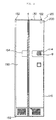
- Fig. 1 is a front view showing the embodiment of the present invention
- Fig. 2 is a front view of the folding doors.
- the folding doors referred to as a whole by the number 100 is set on the opening portion of the front wall 10 of lavatory units and the like.
- the folding doors 100 has a first door panel 150 and a second door panel 110, and the first door panel 150 and the second door panel 110 is connected by a hinge 4 shown in Fig. 15 and a coil spring 5 shown in Fig. 16.
- a pin 152 is planted in the upper and lower portion of the end portion of the first door panel 150, and the folding doors 100 could be supported rotatably by inserting the pin 152 into a hole provided on the opening portion of the wall 10.
- An indicating window 114 shows the occupied/vacancy condition of the lavatory.
- a push board 154 is mounted on the first door panel 150 near the hinge 4.
- the folding doors 100 folds inwardly to the hinge 4, and the door could be opened.
- the folding doors 100 close automatically by the restoring power of the coil spring mounted on the inner side of hinge 4.
- the panel material is in a honeycomb structure to reduce weight thereof.
- the first door panel 150 and the second door panel 110 of the folding doors 100 also takes a honeycomb board structure. Therefore, the surrounding of the door panel is covered with a cover.
- a fixing board 130 serving also as a cover is fixed on the upper portion of the second door panel 110, and a slider 120 and a rotary damper 200 is installed on the fixing board 130.
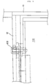
- Fig. 3 shows the joint condition of the wall 10 and the second door panel 110, and it is showing that the slider 120 mounted on the upper portion of the second door panel 110 is inserted to a guide rail 12 mounted on the upper portion of the opening portion of the wall 10.
- Fig. 4 is a structure view of a guiding device equipped on the folding doors of the present invention
- Fig. 5 is a component diagram of the guiding device.
- the guiding device referred to by the number 120 as a whole comprises of a fixing board 124 fixed on the upper portion of the second door panel 110, a rotary damper 200 fixed on the lower portion of the fixing board 124, and a slider 122 fixed on a shaft 210 of the rotary damper 200.
- An upper cover 130 is mounted on the upper portion of the second door panel 110, and a side cover 132 is mounted on the side portion.
- the fixing board 124 of the guiding device 120 could also serve as the upper cover 130, but they could also have a different structure.
- a casing 205 of the rotary damper 200 is held on the lower surface of the fixing board 124 by a fixture 128, and is fixed onto the upper portion of the second door panel 110 by a screw 126.
- a hole 108 for inserting the casing 205 of the rotary damper 200 is provided on the upper portion of the second door panel 110.
- the shaft 210 of the rotary damper 200 goes through the hole formed on the fixing board 124 and extends to the upper direction.
- the slider 122 is mounted on the shaft 210.
- the slider 122 has a quadrilateral plane form and is fixed so as not to rotate against the shaft 210.
- the slider 122 moves linearly through the guide rail 12 of the wall without rotating.
- Fig. 6 shows the locus of the slider 122 and the rotary damper 200 when the folding doors is opened and closed.
- the slider 122 will not rotate, but the case 205 fixed on the side of the second door panel 110 pivotes as the door panel 110 opens, so the angle formed by the shaft 210 and the casing 205 of the rotary damper 200 ranges from angle B to angle A.
- the second door panel 110 and the first door panel 150 moves in the direction of returning to the plane form by the restoring power of the coil spring mounted on the hinge 4 portion.
- the angle formed by the shaft 210 and the casing 205 relatively rotates from angle A to angle B.
- Fig. 7 is a perspective view of the rotary damper 200
- Fig. 8 is a cross sectional view thereof
- Fig. 9 is a cross sectional view of a rotor.
- the rotary damper generally shown as reference 200 includes a casing 205, a damping chamber 220 formed in the casing 205 and a shaft 210 extending through the case 205 for relative rotation.
- a rotor 240 is mounted on the shaft 210 for slidable rotation in the damping chamber 220.
- the damping chamber 220 is filled with a silicone oil 222 to produce a resistance against rotation of the rotor 240.
- the rotor 240 has a tapered hole 242 which contains a ball 244.
- a pin 250 extends through the rotor 240 across the tapered hole 242 to hold the ball 244 in a portion of the tapered hole 242 having a smaller diameter.
- an orifice groove 230 which is configured to reduce the cross sectional area of the silicone oil flow path defined between the side wall of the damping chamber 220 and the lateral portion of the rotor 240 to put a brake force to the rotating motion of the rotor 240.
- Fig. 10 and Fig. 11 are explanatory views showing the rotating directions and a damping function of the rotor 240.
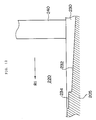
- Fig.12 is an explanatory view showing the shape of the orifice groove 230.
- the orifice groove 230 may have a tapered bottom surface 232 to continuously increase the resistance to the rotor 240 and maximize the resistance at an end of the orifice groove 230 where the depth of the bottom surface 234 is smallest to minimize the cross sectional area of the groove and maximize the resistance to the rotor 240.
- Fig. 13 shows a pressure adjusting valve for releasing the excessive load.
- the ball 244 shuts the tapered hole 242 and produced a damping force.
- a bypass 300 is provided to communicate opposite sides of the damping chamber 220, and a check valve comprising a ball 310 and a spring 320 is provided in the bypass 300.
- the check valve When the pressure in the damping chamber 220 exceeds a predetermined value, the check valve is opened to discharge the excessive pressure.
- the folding doors of the invention has a rotary damper mounted on the door panel guided by rails, so the door closing by spring force receives damping force and it closes smoothly. Therefore, occurance of banging noise etc. could be prevented.
- the spring force could be reinforced if necessary in order to gain a door having high density.
Landscapes
- Engineering & Computer Science (AREA)
- Mechanical Engineering (AREA)
- Extensible Doors And Revolving Doors (AREA)
- Fluid-Damping Devices (AREA)
- Support Devices For Sliding Doors (AREA)
Description
- The present invention relates to a folding door used, for example, as the door of a lavatory in an airplane.
- Folding doors do not use up space when opening and closing the door compared to normal board-type doors, so they are utilized in the lavatory of airplanes, telephone boxes, bath units of houses and the like.
- Fig. 14 is an explanatory view showing the folding doors used in lavatory units of airplanes.
- The folding doors shown as a whole by
reference 1 comprises of afirst door panel 2 and asecond door panel 3, and thefirst door panel 2 and thesecond door panel 3 is connected by ahinge 4. - Fig. 15 is a cross sectional view showing the
hinge 4. It takes a structure wherehinge members panels cover member 4D. - By the engagement of the gear portion of
hinge members door panels cover 4D. - A
coil spring 5 is set in the hinge portion, and forces thedoor panels - Fig. 16 shows the detail of the
coil spring 5. Thecoil spring 5 positioned between thefirst door panel 2 and thesecond door panel 3 forces the foldedpanels - A
door locking device 8 is set on thesecond door panel 3. Apin 6 is planted on the end portion of thefirst door panel 2, and supports thewhole folding doors 1 rotatably on the side of the wall of the lavatory unit. - A guiding
device 7 is set on the upper portion of thesecond door panel 3, and it enables thesecond door panel 3 to open and close along the door opening portion of the lavatory unit. - Fig. 17 shows the detail of the guiding
device 7. The guidingdevice 7 set on the upper portion of thesecond door panel 3 includes a slider 7A and ashaft 7B which supports the slider 7A. The slider 7A, for example, has a quadrilateral plane form, and fits in theguide rail 9 formed on the door opening portion. - When the
second door panel 3 opens or closes, the slider 7A guides the second door panel smoothly by sliding through theguide rail 9. - When the plane form of the slider 7A is a quadrilateral, the slider 7A takes a straight line movement and the
door panel 3 takes a gyrating movement, so the slider 7A rotates against theshaft 7B. - In the folding doors having the above mentioned structure, the spring modulus of the
coil spring 5 needs to be increased in order to improve the sealing ability of the door. - When the spring modulus of the
coil spring 5 is increased, the folded twodoor panels - The lavatory units of airplanes especially are placed near passenger seats, and many people use the unit while other passengers are asleep. Therefore, it is necessary to prevent the bumping noise that the folding doors make when being shut.
- The present invention aims at offering folding doors that can be opened and closed smoothly, and at the same time prevent the bumping noise that the door makes when being shut.
- The folding door of the present invention according to
claim 1 comprises of a guiding rail provided in use on the door opening portion, a slider mounted on the second door panel by a rotation axis and which slides inside the guiding rail, and a rotary damper which damps the rotating power of the rotation axis. - The folding door preferably has a forcing means on the connecting portion of the first door panel and the second door panel to restore the first door panel and the second door panel to a plane state.
-
- Fig. 1 is a front view showing the embodiment of the present invention;
- Fig. 2 is a front view of the folding doors;
- Fig. 3 is an explanatory diagram showing the guiding structure of the folding doors;
- Fig. 4 is a structure view of the guiding device;
- Fig. 5 is a component diagram of the guiding device;
- Fig. 6 is an explanatory diagram showing the locus of the opening and closing of the folding doors;
- Fig. 7 is a schematic view of a rotary damper;
- Fig. 8 is a cross sectional view of the rotary damper;
- Fig. 9 is a cross sectional view of a rotor;
- Fig. 10 is an explanatory diagram illustrating the damping operation of the rotor;
- Fig. 11 is an explanatory diagram illustrating the damping operation of the rotor;
- Fig. 12 is a cross sectional view of an orifice groove;
- Fig. 13 is an explanatory diagram of a pressure adjusting valve;
- Fig. 14 is a schematic view of the folding doors used in priort art lavatory units;
- Fig. 15 is a cross sectional view of the hinge of fig.14;
- Fig. 16 is an explanatory diagram of the coil spring of fig.14; and
- Fig. 17 is an explanatory view of the guiding device of fig.14.
- Fig. 1 is a front view showing the embodiment of the present invention, and Fig. 2 is a front view of the folding doors. The folding doors referred to as a whole by the
number 100 is set on the opening portion of thefront wall 10 of lavatory units and the like. - The
folding doors 100 has afirst door panel 150 and asecond door panel 110, and thefirst door panel 150 and thesecond door panel 110 is connected by ahinge 4 shown in Fig. 15 and acoil spring 5 shown in Fig. 16. - A
pin 152 is planted in the upper and lower portion of the end portion of thefirst door panel 150, and the foldingdoors 100 could be supported rotatably by inserting thepin 152 into a hole provided on the opening portion of thewall 10. - An indicating
window 114 shows the occupied/vacancy condition of the lavatory. When the user enters and operates theknob 8 mounted on the inside of thesecond door panel 110, thesecond door panel 110 will be fastened to thewall 10 side, and the indicatingwindow 114 will indicate that the lavatory is occupied. - A
push board 154 is mounted on thefirst door panel 150 near thehinge 4. When the user pushes thepush board 154, the foldingdoors 100 folds inwardly to thehinge 4, and the door could be opened. When the pushing force is removed, the foldingdoors 100 close automatically by the restoring power of the coil spring mounted on the inner side ofhinge 4. - In lavatory units of airplanes and the like, the panel material is in a honeycomb structure to reduce weight thereof. The
first door panel 150 and thesecond door panel 110 of the foldingdoors 100 also takes a honeycomb board structure. Therefore, the surrounding of the door panel is covered with a cover. Afixing board 130 serving also as a cover is fixed on the upper portion of thesecond door panel 110, and aslider 120 and arotary damper 200 is installed on thefixing board 130. - Fig. 3 shows the joint condition of the
wall 10 and thesecond door panel 110, and it is showing that theslider 120 mounted on the upper portion of thesecond door panel 110 is inserted to aguide rail 12 mounted on the upper portion of the opening portion of thewall 10. - Fig. 4 is a structure view of a guiding device equipped on the folding doors of the present invention, and Fig. 5 is a component diagram of the guiding device.
- The guiding device referred to by the
number 120 as a whole comprises of afixing board 124 fixed on the upper portion of thesecond door panel 110, arotary damper 200 fixed on the lower portion of thefixing board 124, and aslider 122 fixed on ashaft 210 of therotary damper 200. - An
upper cover 130 is mounted on the upper portion of thesecond door panel 110, and aside cover 132 is mounted on the side portion. The fixingboard 124 of the guidingdevice 120 could also serve as theupper cover 130, but they could also have a different structure. - A
casing 205 of therotary damper 200 is held on the lower surface of the fixingboard 124 by afixture 128, and is fixed onto the upper portion of thesecond door panel 110 by ascrew 126. Ahole 108 for inserting thecasing 205 of therotary damper 200 is provided on the upper portion of thesecond door panel 110. - The
shaft 210 of therotary damper 200 goes through the hole formed on the fixingboard 124 and extends to the upper direction. Theslider 122 is mounted on theshaft 210. - The
slider 122 has a quadrilateral plane form and is fixed so as not to rotate against theshaft 210. Theslider 122 moves linearly through theguide rail 12 of the wall without rotating. - Fig. 6 shows the locus of the
slider 122 and therotary damper 200 when the folding doors is opened and closed. - When the
first door panel 150 and thesecond door panel 110 is folded inwardly with thehinge 4 in the center, theslider 122 moves linearly toward the fixingpin 152 of thefirst door panel 150. - The
slider 122 will not rotate, but thecase 205 fixed on the side of thesecond door panel 110 pivotes as thedoor panel 110 opens, so the angle formed by theshaft 210 and thecasing 205 of therotary damper 200 ranges from angle B to angle A. - When the user lets go of the folding doors, the
second door panel 110 and thefirst door panel 150 moves in the direction of returning to the plane form by the restoring power of the coil spring mounted on thehinge 4 portion. By this movement, the angle formed by theshaft 210 and thecasing 205 relatively rotates from angle A to angle B. - Therefore, by operating a damping force between the
casing 205 and theshaft 210 of therotary damper 200, the folding doors could be smoothly and quietly closed. - Fig. 7 is a perspective view of the
rotary damper 200, Fig. 8 is a cross sectional view thereof; and Fig. 9 is a cross sectional view of a rotor. - The rotary damper generally shown as
reference 200 includes acasing 205, a dampingchamber 220 formed in thecasing 205 and ashaft 210 extending through thecase 205 for relative rotation. Arotor 240 is mounted on theshaft 210 for slidable rotation in the dampingchamber 220. The dampingchamber 220 is filled with asilicone oil 222 to produce a resistance against rotation of therotor 240. - The
rotor 240 has a taperedhole 242 which contains aball 244. Apin 250 extends through therotor 240 across the taperedhole 242 to hold theball 244 in a portion of the taperedhole 242 having a smaller diameter. - In the side wall of the damping
chamber 220 is provided anorifice groove 230 which is configured to reduce the cross sectional area of the silicone oil flow path defined between the side wall of the dampingchamber 220 and the lateral portion of therotor 240 to put a brake force to the rotating motion of therotor 240. - Fig. 10 and Fig. 11 are explanatory views showing the rotating directions and a damping function of the
rotor 240. Fig.12 is an explanatory view showing the shape of theorifice groove 230. - With reference to fig. 10, when the
shaft 210 and therotor 240 rotate in the dampingchamber 220 in the direction shown by arrow R1, silicone oil passing through the taperedhole 242 brings theball 244 to the smaller diameter portion so as to shut thetapered hole 242 with theball 244. Then, the silicone oil pressurized by therotor 240 can flow to the back side of therotor 240 only through theorifice groove 230. Therefore, by designing theorifice groove 230 to vary in effective cross sectional area in response to the rotating angle of therotor 240, the damping force (braking force to the rotor) can be adjusted in response to the rotational position of therotor 240. - As shown in Fig. 11, when the
rotor 240 rotates in the direction shown by arrow R2, the flow of the silicone oil pushes theball 244 back to the position of thepin 250. As a result, thetapered hole 242 is opened and permits the silicone oil to flow through both thetapered hole 242 and theorifice groove 230. Therefore, the resistance applied to therotor 240 is reduced. - The
orifice groove 230, as shown in Fig. 12, may have a taperedbottom surface 232 to continuously increase the resistance to therotor 240 and maximize the resistance at an end of theorifice groove 230 where the depth of thebottom surface 234 is smallest to minimize the cross sectional area of the groove and maximize the resistance to therotor 240. - If a user attempts to close the door by force, the door and the damper receive an excessive load.
- Fig. 13 shows a pressure adjusting valve for releasing the excessive load. When the
rotor 240 moves in the arrow R1 direction in the dampingchamber 220, theball 244 shuts the taperedhole 242 and produced a damping force. When a user tries to close the door with force, the pressure in the silicone oil in the dampingchamber 220 will increase too much. In order to adjust the extraordinary pressure in the silicone oil, abypass 300 is provided to communicate opposite sides of the dampingchamber 220, and a check valve comprising aball 310 and aspring 320 is provided in thebypass 300. - When the pressure in the damping
chamber 220 exceeds a predetermined value, the check valve is opened to discharge the excessive pressure. - As described above, the folding doors of the invention has a rotary damper mounted on the door panel guided by rails, so the door closing by spring force receives damping force and it closes smoothly. Therefore, occurance of banging noise etc. could be prevented.
- Because a damper is mounted, the spring force could be reinforced if necessary in order to gain a door having high density.
Claims (4)
- A folding door (100) comprising:a first door panel (150) rotatably supported in use at one side portion of the door opening portion;a second door panel (110) mounted foldably by a hinge (4) to the first door panel (150); anda guiding device (120) which guides the second door panel (110) along the door opening portion;wherein the guiding device comprises of;a guiding rail (12) fixed in use on the door opening portion;a slider (122) mounted on the second door panel (110) for rotation about an axis perpendicular to the top edge of the second door panel and being so as to slide without relative rotation inside the guiding rail (12); anda rotary damper (200) acting between said slider and said second door panel so as to oppose rotation about said rotation axis.
- A folding door claimed in Claim 1 further comprising, a forcing means (5) at the connecting portion of the first door panel (150) and the second door panel (110) for restoring the first door panel (150) and the second door panel (110) to a plane state.
- A folding door claimed in Claim 1 wherein the rotary damper (200) comprising:a case (205) and a damping chamber (220) formed inside the case (205);liquid (222) filled inside the damping chamber (220);a shaft (210) going through the damping chamber (220);a rotor (240) connected to the shaft (210) and slidably rotates inside the damping chamber (220);a check valve mounted on the rotor (240); andan orifice groove (230) formed in the side wall of the damping chamber (220).
- A folding door claimed in Claim 3 wherein, the orifice groove (230) formed in the damping chamber (220) of the rotary damper (200) is formed so that the damping power increases as the first door panel (150) and the second door panel (110) reverts to a plane state.
Applications Claiming Priority (2)
| Application Number | Priority Date | Filing Date | Title |
|---|---|---|---|
| JP15184193A JP3280756B2 (en) | 1993-06-23 | 1993-06-23 | Folding door for aircraft |
| JP151841/93 | 1993-06-23 |
Publications (2)
| Publication Number | Publication Date |
|---|---|
| EP0631030A1 EP0631030A1 (en) | 1994-12-28 |
| EP0631030B1 true EP0631030B1 (en) | 1997-03-12 |
Family
ID=15527464
Family Applications (1)
| Application Number | Title | Priority Date | Filing Date |
|---|---|---|---|
| EP93118232A Expired - Lifetime EP0631030B1 (en) | 1993-06-23 | 1993-11-10 | Folding doors |
Country Status (5)
| Country | Link |
|---|---|
| US (1) | US5435372A (en) |
| EP (1) | EP0631030B1 (en) |
| JP (1) | JP3280756B2 (en) |
| DE (1) | DE69308827T2 (en) |
| ES (1) | ES2098632T3 (en) |
Families Citing this family (15)
| Publication number | Priority date | Publication date | Assignee | Title |
|---|---|---|---|---|
| JP3065815U (en) * | 1999-07-15 | 2000-02-08 | 株式会社ジャムコ | Laboratory unit door |
| JP2002115269A (en) * | 2000-09-29 | 2002-04-19 | Komatsu Utility Europe Spa | Earthmoving machine driving room |
| JP4531284B2 (en) | 2001-04-03 | 2010-08-25 | 株式会社ジャムコ | Attendant call lamp reset switch |
| US7051780B2 (en) * | 2002-03-29 | 2006-05-30 | Skylock Industries, Inc. | Latch assembly for a bifold cockpit door |
| USD673207S1 (en) * | 2009-06-03 | 2012-12-25 | Roland Corporation | Keyboard cover for electric piano |
| JP5251745B2 (en) * | 2009-06-12 | 2013-07-31 | 横浜ゴム株式会社 | Door lock device |
| JP5487745B2 (en) | 2009-06-12 | 2014-05-07 | 横浜ゴム株式会社 | Door opening and closing device |
| DE102011120839B4 (en) | 2011-12-13 | 2016-02-25 | Diehl Comfort Modules GmbH | Automatically operated door system for an aircraft toilet |
| DE102012004441B4 (en) | 2012-03-03 | 2016-08-04 | Diehl Comfort Modules GmbH | Door system for a built-in module in an aircraft and a built-in module for an aircraft |
| CN104420751B (en) | 2013-08-20 | 2016-12-28 | 李祯祥 | Hinge devices for folding doors |
| WO2015148813A1 (en) * | 2014-03-27 | 2015-10-01 | C&D Zodiac, Inc. | Bi-fold door module |
| US9428259B2 (en) | 2014-03-27 | 2016-08-30 | C&D Zodiac, Inc. | Bi-fold door module |
| AU2019277194A1 (en) | 2018-05-30 | 2020-12-24 | MGB Rentals Pty Ltd | Hinge system for the lid of a waste bin |
| US20250108905A1 (en) * | 2023-10-02 | 2025-04-03 | The Boeing Company | Barrier Door with Stowage Frame |
| US20250304235A1 (en) * | 2024-03-28 | 2025-10-02 | The Boeing Company | Door Assembly with an Engagement Assembly |
Family Cites Families (6)
| Publication number | Priority date | Publication date | Assignee | Title |
|---|---|---|---|---|
| US3385344A (en) * | 1966-03-10 | 1968-05-28 | Leigh Prod Inc | Bi-fold door structure |
| US3387320A (en) * | 1966-11-07 | 1968-06-11 | Ideal Security Hardware Co | Rotary hydraulic door closer |
| US3494408A (en) * | 1968-11-20 | 1970-02-10 | Dante R D Ercole | Folding door construction |
| US3987837A (en) * | 1974-09-16 | 1976-10-26 | Hewson Kenneth E | Bi-fold door assembly |
| US4064590A (en) * | 1976-07-02 | 1977-12-27 | Smith Lester L | Top guide pivot for bifold doors |
| JPS582848Y2 (en) * | 1977-12-29 | 1983-01-18 | ワイケイケイ株式会社 | Folding door door roller device |
-
1993
- 1993-06-23 JP JP15184193A patent/JP3280756B2/en not_active Expired - Fee Related
- 1993-11-10 EP EP93118232A patent/EP0631030B1/en not_active Expired - Lifetime
- 1993-11-10 DE DE69308827T patent/DE69308827T2/en not_active Expired - Lifetime
- 1993-11-10 ES ES93118232T patent/ES2098632T3/en not_active Expired - Lifetime
- 1993-11-12 US US08/150,817 patent/US5435372A/en not_active Expired - Lifetime
Also Published As
| Publication number | Publication date |
|---|---|
| US5435372A (en) | 1995-07-25 |
| JPH0711836A (en) | 1995-01-13 |
| EP0631030A1 (en) | 1994-12-28 |
| ES2098632T3 (en) | 1997-05-01 |
| DE69308827T2 (en) | 1997-10-09 |
| JP3280756B2 (en) | 2002-05-13 |
| DE69308827D1 (en) | 1997-04-17 |
Similar Documents
| Publication | Publication Date | Title |
|---|---|---|
| US5435372A (en) | Smooth opening/closing multiple panel folding spring, or the like, biased folding doors | |
| US6817062B2 (en) | Door hinge apparatus having a door checking function | |
| US5524979A (en) | Overhead storage mechanism | |
| CA2789982C (en) | Door closer, particularly for glass doors | |
| US6292981B1 (en) | Crescent hinge | |
| US20040227439A1 (en) | Device for damping the movement of movable furniture parts in their closing region | |
| US8677561B2 (en) | Automatic door closure unit | |
| US8079450B2 (en) | Viscous strand damper assembly | |
| US5193228A (en) | Toilet covering hinge assembly with damping capability | |
| CZ297729B6 (en) | Braking retardation apparatus for doors, windows or furniture extensible parts | |
| US4383392A (en) | Dual-cam guided four-bar linkage mechanism for an overhead baggage compartment | |
| US5938306A (en) | Cabinet and door assembly | |
| US20030117047A1 (en) | Lift method for storage bin door | |
| JPS594772A (en) | Jig for obliquely opened ittings | |
| CA1199349A (en) | Device for automatically closing door | |
| JP3770641B2 (en) | Door with finger padding prevention device | |
| KR100514606B1 (en) | Transfer unit of revolution door | |
| KR102286197B1 (en) | Damper apparatus of door) | |
| JP3267350B2 (en) | Hinge for swing door | |
| CN115230595A (en) | Vehicle interior panel with disappearing door | |
| WO2024159208A1 (en) | Dual axis automotive interior panel system | |
| KR19980076949A (en) | Hinge Unit on Refrigerator Door | |
| EP4530426A1 (en) | Pivot hinge with locking mechanism for 180° opening and closing for doors of cabinets and furniture in general | |
| KR0182897B1 (en) | Side door support for a car | |
| JPH06189872A (en) | Toilet unit |
Legal Events
| Date | Code | Title | Description |
|---|---|---|---|
| PUAI | Public reference made under article 153(3) epc to a published international application that has entered the european phase |
Free format text: ORIGINAL CODE: 0009012 |
|
| AK | Designated contracting states |
Kind code of ref document: A1 Designated state(s): CH DE ES FR GB IT LI NL |
|
| 17P | Request for examination filed |
Effective date: 19950421 |
|
| GRAG | Despatch of communication of intention to grant |
Free format text: ORIGINAL CODE: EPIDOS AGRA |
|
| 17Q | First examination report despatched |
Effective date: 19960515 |
|
| GRAH | Despatch of communication of intention to grant a patent |
Free format text: ORIGINAL CODE: EPIDOS IGRA |
|
| GRAH | Despatch of communication of intention to grant a patent |
Free format text: ORIGINAL CODE: EPIDOS IGRA |
|
| GRAA | (expected) grant |
Free format text: ORIGINAL CODE: 0009210 |
|
| AK | Designated contracting states |
Kind code of ref document: B1 Designated state(s): CH DE ES FR GB IT LI NL |
|
| REG | Reference to a national code |
Ref country code: CH Ref legal event code: EP |
|
| REG | Reference to a national code |
Ref country code: CH Ref legal event code: NV Representative=s name: A. BRAUN, BRAUN, HERITIER, ESCHMANN AG PATENTANWAE |
|
| REF | Corresponds to: |
Ref document number: 69308827 Country of ref document: DE Date of ref document: 19970417 |
|
| ET | Fr: translation filed | ||
| REG | Reference to a national code |
Ref country code: ES Ref legal event code: FG2A Ref document number: 2098632 Country of ref document: ES Kind code of ref document: T3 |
|
| ITF | It: translation for a ep patent filed | ||
| PG25 | Lapsed in a contracting state [announced via postgrant information from national office to epo] |
Ref country code: LI Free format text: LAPSE BECAUSE OF NON-PAYMENT OF DUE FEES Effective date: 19971130 Ref country code: CH Free format text: LAPSE BECAUSE OF NON-PAYMENT OF DUE FEES Effective date: 19971130 |
|
| PLBE | No opposition filed within time limit |
Free format text: ORIGINAL CODE: 0009261 |
|
| STAA | Information on the status of an ep patent application or granted ep patent |
Free format text: STATUS: NO OPPOSITION FILED WITHIN TIME LIMIT |
|
| 26N | No opposition filed | ||
| PG25 | Lapsed in a contracting state [announced via postgrant information from national office to epo] |
Ref country code: NL Free format text: LAPSE BECAUSE OF NON-PAYMENT OF DUE FEES Effective date: 19980601 |
|
| REG | Reference to a national code |
Ref country code: CH Ref legal event code: PL |
|
| NLV4 | Nl: lapsed or anulled due to non-payment of the annual fee |
Effective date: 19980601 |
|
| REG | Reference to a national code |
Ref country code: GB Ref legal event code: IF02 |
|
| PG25 | Lapsed in a contracting state [announced via postgrant information from national office to epo] |
Ref country code: IT Free format text: LAPSE BECAUSE OF NON-PAYMENT OF DUE FEES;WARNING: LAPSES OF ITALIAN PATENTS WITH EFFECTIVE DATE BEFORE 2007 MAY HAVE OCCURRED AT ANY TIME BEFORE 2007. THE CORRECT EFFECTIVE DATE MAY BE DIFFERENT FROM THE ONE RECORDED. Effective date: 20051110 |
|
| PGFP | Annual fee paid to national office [announced via postgrant information from national office to epo] |
Ref country code: DE Payment date: 20121130 Year of fee payment: 20 Ref country code: FR Payment date: 20121122 Year of fee payment: 20 |
|
| PGFP | Annual fee paid to national office [announced via postgrant information from national office to epo] |
Ref country code: GB Payment date: 20121107 Year of fee payment: 20 Ref country code: ES Payment date: 20121030 Year of fee payment: 20 |
|
| REG | Reference to a national code |
Ref country code: DE Ref legal event code: R071 Ref document number: 69308827 Country of ref document: DE |
|
| REG | Reference to a national code |
Ref country code: GB Ref legal event code: PE20 Expiry date: 20131109 |
|
| PG25 | Lapsed in a contracting state [announced via postgrant information from national office to epo] |
Ref country code: GB Free format text: LAPSE BECAUSE OF EXPIRATION OF PROTECTION Effective date: 20131109 Ref country code: DE Free format text: LAPSE BECAUSE OF EXPIRATION OF PROTECTION Effective date: 20131112 |
|
| REG | Reference to a national code |
Ref country code: ES Ref legal event code: FD2A Effective date: 20140925 |
|
| PG25 | Lapsed in a contracting state [announced via postgrant information from national office to epo] |
Ref country code: ES Free format text: LAPSE BECAUSE OF EXPIRATION OF PROTECTION Effective date: 20131111 |