EP0630097A2 - Electric machine control system with rotor position encoder - Google Patents
Electric machine control system with rotor position encoder Download PDFInfo
- Publication number
- EP0630097A2 EP0630097A2 EP94304056A EP94304056A EP0630097A2 EP 0630097 A2 EP0630097 A2 EP 0630097A2 EP 94304056 A EP94304056 A EP 94304056A EP 94304056 A EP94304056 A EP 94304056A EP 0630097 A2 EP0630097 A2 EP 0630097A2
- Authority
- EP
- European Patent Office
- Prior art keywords
- rotor
- parts
- stator
- encoder
- sequence
- Prior art date
- Legal status (The legal status is an assumption and is not a legal conclusion. Google has not performed a legal analysis and makes no representation as to the accuracy of the status listed.)
- Granted
Links
Images


Classifications
-
- H—ELECTRICITY
- H02—GENERATION; CONVERSION OR DISTRIBUTION OF ELECTRIC POWER
- H02P—CONTROL OR REGULATION OF ELECTRIC MOTORS, ELECTRIC GENERATORS OR DYNAMO-ELECTRIC CONVERTERS; CONTROLLING TRANSFORMERS, REACTORS OR CHOKE COILS
- H02P1/00—Arrangements for starting electric motors or dynamo-electric converters
- H02P1/16—Arrangements for starting electric motors or dynamo-electric converters for starting dynamo-electric motors or dynamo-electric converters
- H02P1/163—Arrangements for starting electric motors or dynamo-electric converters for starting dynamo-electric motors or dynamo-electric converters for starting an individual reluctance motor
-
- G—PHYSICS
- G01—MEASURING; TESTING
- G01D—MEASURING NOT SPECIALLY ADAPTED FOR A SPECIFIC VARIABLE; ARRANGEMENTS FOR MEASURING TWO OR MORE VARIABLES NOT COVERED IN A SINGLE OTHER SUBCLASS; TARIFF METERING APPARATUS; MEASURING OR TESTING NOT OTHERWISE PROVIDED FOR
- G01D5/00—Mechanical means for transferring the output of a sensing member; Means for converting the output of a sensing member to another variable where the form or nature of the sensing member does not constrain the means for converting; Transducers not specially adapted for a specific variable
- G01D5/12—Mechanical means for transferring the output of a sensing member; Means for converting the output of a sensing member to another variable where the form or nature of the sensing member does not constrain the means for converting; Transducers not specially adapted for a specific variable using electric or magnetic means
- G01D5/244—Mechanical means for transferring the output of a sensing member; Means for converting the output of a sensing member to another variable where the form or nature of the sensing member does not constrain the means for converting; Transducers not specially adapted for a specific variable using electric or magnetic means influencing characteristics of pulses or pulse trains; generating pulses or pulse trains
- G01D5/249—Mechanical means for transferring the output of a sensing member; Means for converting the output of a sensing member to another variable where the form or nature of the sensing member does not constrain the means for converting; Transducers not specially adapted for a specific variable using electric or magnetic means influencing characteristics of pulses or pulse trains; generating pulses or pulse trains using pulse code
- G01D5/2492—Pulse stream
-
- G—PHYSICS
- G01—MEASURING; TESTING
- G01P—MEASURING LINEAR OR ANGULAR SPEED, ACCELERATION, DECELERATION, OR SHOCK; INDICATING PRESENCE, ABSENCE, OR DIRECTION, OF MOVEMENT
- G01P3/00—Measuring linear or angular speed; Measuring differences of linear or angular speeds
- G01P3/42—Devices characterised by the use of electric or magnetic means
- G01P3/44—Devices characterised by the use of electric or magnetic means for measuring angular speed
- G01P3/48—Devices characterised by the use of electric or magnetic means for measuring angular speed by measuring frequency of generated current or voltage
- G01P3/481—Devices characterised by the use of electric or magnetic means for measuring angular speed by measuring frequency of generated current or voltage of pulse signals
-
- H—ELECTRICITY
- H02—GENERATION; CONVERSION OR DISTRIBUTION OF ELECTRIC POWER
- H02K—DYNAMO-ELECTRIC MACHINES
- H02K29/00—Motors or generators having non-mechanical commutating devices, e.g. discharge tubes or semiconductor devices
- H02K29/06—Motors or generators having non-mechanical commutating devices, e.g. discharge tubes or semiconductor devices with position sensing devices
-
- H—ELECTRICITY
- H02—GENERATION; CONVERSION OR DISTRIBUTION OF ELECTRIC POWER
- H02P—CONTROL OR REGULATION OF ELECTRIC MOTORS, ELECTRIC GENERATORS OR DYNAMO-ELECTRIC CONVERTERS; CONTROLLING TRANSFORMERS, REACTORS OR CHOKE COILS
- H02P6/00—Arrangements for controlling synchronous motors or other dynamo-electric motors using electronic commutation dependent on the rotor position; Electronic commutators therefor
- H02P6/14—Electronic commutators
- H02P6/16—Circuit arrangements for detecting position
-
- H—ELECTRICITY
- H02—GENERATION; CONVERSION OR DISTRIBUTION OF ELECTRIC POWER
- H02P—CONTROL OR REGULATION OF ELECTRIC MOTORS, ELECTRIC GENERATORS OR DYNAMO-ELECTRIC CONVERTERS; CONTROLLING TRANSFORMERS, REACTORS OR CHOKE COILS
- H02P6/00—Arrangements for controlling synchronous motors or other dynamo-electric motors using electronic commutation dependent on the rotor position; Electronic commutators therefor
- H02P6/20—Arrangements for starting
- H02P6/22—Arrangements for starting in a selected direction of rotation
-
- H—ELECTRICITY
- H02—GENERATION; CONVERSION OR DISTRIBUTION OF ELECTRIC POWER
- H02K—DYNAMO-ELECTRIC MACHINES
- H02K29/00—Motors or generators having non-mechanical commutating devices, e.g. discharge tubes or semiconductor devices
- H02K29/06—Motors or generators having non-mechanical commutating devices, e.g. discharge tubes or semiconductor devices with position sensing devices
- H02K29/08—Motors or generators having non-mechanical commutating devices, e.g. discharge tubes or semiconductor devices with position sensing devices using magnetic effect devices, e.g. Hall-plates, magneto-resistors
-
- H—ELECTRICITY
- H02—GENERATION; CONVERSION OR DISTRIBUTION OF ELECTRIC POWER
- H02K—DYNAMO-ELECTRIC MACHINES
- H02K29/00—Motors or generators having non-mechanical commutating devices, e.g. discharge tubes or semiconductor devices
- H02K29/06—Motors or generators having non-mechanical commutating devices, e.g. discharge tubes or semiconductor devices with position sensing devices
- H02K29/10—Motors or generators having non-mechanical commutating devices, e.g. discharge tubes or semiconductor devices with position sensing devices using light effect devices
Definitions
- This invention relates to control systems for electric machines, an encoder for an electric machine from which the position of the rotor relative to the stator is derivable and methods of starting electric machines.
- the invention is particularly, though not exclusively, applicable to switched reluctance (SR) machines.
- the switched reluctance drive is a variable-speed drive system comprising an electric motor supplied from a power-electronic converter under the control of low-power control electronics.
- the motor has salient poles on both the stator and the rotor, typically with an excitation coil around each stator pole. These stator coils are grouped to form one or more phase windings.
- the electrical currents in the windings are typically switched on and off by power-electronic switches.
- the timing of the switching of the currents in the windings is controlled in relation to the relative angular position of the stator and rotor poles.
- This relative position may be detected by a rotor position transducer which consists of a rotating member and stationary sensors which supply signals to the control electronics.
- a rotor position transducer which consists of a rotating member and stationary sensors which supply signals to the control electronics.
- motors with more than two phases generally use more than one sensor according to the prior art.
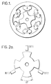
- Figure 1 shows a schematic diagram of a typical 3-phase SR motor, which has six stator poles and four rotor poles.
- the poles carrying coils A and A' have opposite magnetic polarisation.
- Phases B and C are formed similarly.
- a rotor position transducer (RPT) is used to ensure that the currents of the phase windings are switched on and off at the appropriate angles of rotation.
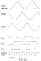
- Figure 2a illustrates a typical system consisting of a rotating slotted disc and three optical sensors which are switched by the rotation of the disc.
- Figure 2b shows the idealised variation of the inductances of the phase windings as functions of angle of rotation ⁇ .
- Positive torque is defined as that which acts in the direction to move the rotor in the direction of positively increasing ⁇ .
- Such torque is produced by any phase when the winding of that phase carries current and the angle of rotation is such that the inductance is increasing with increasing ⁇ .
- Negative torque is produced when a phase carries current during that part of its inductance cycle where the inductance is decreasing with increasing ⁇ (or increasing with decreasing ⁇ ).
- FIG 2b also shows the three output signals of the sensors according to prior art.
- the RPT consists of three sensors, which may for example, be optical, magnetic or inductive, which cooperate with a rotating member, for example a disc with cut out slits, to produce signals such as those shown in Figure 2b as RPT A , RPT B and RPT C .
- the signal RPT A changes from zero to a positive value at the centre of the minimum inductance region of phase A and returns to zero at the maximum inductance position of phase A.
- the signals RPT B and RPT C behave in the same manner for phases B and C respectively. It will be clear that whether the rotor is starting from rest in either the forward or backward direction or running in either direction, the RPT signals enable the control electronics to excite the appropriate phase winding over the appropriate angle of rotation to produce torque in the desired direction.
- the torque developed by the motor may be controlled at low speeds by adjusting the magnitude of the current in the phase windings over the fixed angle defined by the respective positive or negative RPT signals depending on the desired direction of torque.
- the torque is normally controlled by adjusting the angle over which a phase winding is switched onto the power supply and the angle with respect to the inductance cycle at which the switching on takes place, i.e. by timing the switching on and off of the phase energisation with reference to the RPT signals.
- the combined RPT signals can be used to determine the rotor position to one sixth of a phase period thus giving a 15 degree resolution.
- each of these six regions can be interpolated, for example, by using a high frequency pulse train which is phase locked to the low frequency RPT signals as described in GB 1597790 (Stephenson).
- US 4990843 (Moren) describes a method by which the three detectors of Figure 2a may be replaced by a single detector.
- the rotating disc incorporates six or twelve slots, giving a sensor signal which has respectively a rising or falling edge every 30 degrees of rotation, or a falling edge every 30 degrees of rotation, which may be used to switch the phase winding currents of the motor.
- the method suffers from the serious disadvantage that correct tracking of the relationship between edges and phases may be lost due to electrical noise, for example, in the sensor signal.
- a control system for an electric machine having a rotor defining rotor poles arranged to rotate relative to a stator
- the system comprising a controller, switch means for the or each phase of the motor which switch means are actuatable by the controller, a set of features arranged to rotate with the rotor and a single sensor arranged to be influenced by the features as they rotate with the rotor to produce an output receivable by the controller, the features defining the output of the sensor in the form of a digital code which is periodic with the phase inductance cycle of the machine, the code being decodable by the controller to indicate the positions of the rotor poles in the rotor cycle relative to the stator.
- phase inductance cycle is meant the inductance of the machine as seen from the terminals of the or each phase winding.
- the phase inductance cycle is a function of rotor position and varies cyclically within the rotor cycle between given inductance values, for example inductance maxima or minima.
- a rotor position encoder defining a position code for a rotor of an electric machine relative to its stator
- the encoder comprising a set of features mountable to rotate with the rotor for influencing the output of a sensor, the features having sensor output influencing first parts which are in evenly spaced angular positions, and sensor output influencing second parts which are in unevenly spaced angular positions, the said angular positions of the second parts relative to the first parts being decodable as a sequence such that the position of the rotor relative to the stator is determinable from the sequence.
- the period of the said sequence may coincide with the period of the phase inductance cycle.
- the period of the sequence could equally well be a submultiple of the period of the phase inductance cycle or it could be periodic with one revolution of the rotor. In any of these cases the state of the sequence is decodable to determine the rotor position within the phase inductance cycle.
- the evenly spaced first parts may coincide with the power switching actuation positions, or otherwise indicate the positions of the rotor poles as they rotate from which indications of switching timing can be derived, and the second parts create the code by their respective positions relative to adjacent first parts.
- the code can be used to check the rotor position as well as to determine it. For example, if an electrical noise spike corrupted the sensor output the counting from the first parts of the code would be in error. The reestablishment of a correct code can then be used to establish the position of the rotor relative to the stator and to correct positional information counted from the passing first parts.
- the first and second parts of the features of the encoder are associated, such that the second parts are interjacent the first parts.
- the encoder may have a first encoder portion bearing the first parts and a separate portion bearing the second parts which define the sequence independently of the positions of the first parts.
- the encoder is conveniently a discate member mountable on a rotor shaft.
- the features may influence the sensor magnetically, by means of the Hall effect, through light transmissive/non-transmissive parts or light reflective/absorbing parts, by capacitive or inductive effects or by other known means.
- One advantage of the invention is that only one detector is required to determine reliably the position of the rotor relative to the stator.
- only one sensor is required to determine both the switching timing for the electric machine switching means and the position of the rotor relative to the stator. From one sensor it is also possible to tell when an error is induced in the rotor position sensor output and to reestablish the correct positional information thereafter from the subsequent output from the sensor.
- the invention also extends to an electric machine control system
- an encoder according to the invention operably connected to rotate with the machine
- a sensor arranged to be influenced by the features on the encoder to produce a coded signal output
- control means including signal storage means, supplied with the output from the sensor and operable to store the sequence to determine the position of the rotor relative to the stator from the state of the sequence, and machine phase switching means which are actuatable according to the position of the rotor relative to the stator.
- the sensor may be arranged to provide a signal transition, e.g. a rising or falling edge, to denote the passage of the first or second part of the feature.
- a signal transition e.g. a rising or falling edge
- transitions in one sense indicate the first parts and the interjacent transitions in the opposite sense indicate the second parts.
- successive transitions in the same sense could be used to indicate the passage of first and second parts of the features alternately.
- the control means may also include clock means for determining the interval between transitions, and decoding means arranged to decode the intervals between transitions in the sequence.
- the decoding means may be operable to distinguish between binary states on the basis of the interval between transitions, the interval being determined relative to the rate of rotation of the rotor.
- the means include shift register means for receiving the sequence serially as the rotor rotates.
- the shift register is readable by the control means to determine the state of the sequence.
- a control system for an electric machine comprising a sensor, an encoder operably connected to rotate with the machine, the encoder defining a position code for a rotor of the polyphase electric machine relative to its stator, the encoder comprising: a set of features mountable to rotate with the rotor for influencing the output of the sensor, the features having sensor output influencing first parts which are in evenly spaced angular positions and sensor output influencing second parts which are in unevenly spaced angular positions, the said angular positions of the second parts relative to the first parts being decodable as a sequence such that the position of the rotor relative to the stator is determinable from the sequence; the system further including control means, including signal storage means, supplied with the output from the sensor and operable to store the sequence to determine the position of the rotor relative to the stator from the state of the sequence; and machine phase switching means which are actuatable by the control means according to the determined position of the rotor relative to the stator.
- the invention also extends to a method of controlling an electric machine which includes an encoder defining a position code for a rotor of the electric machine relative to its stator, the encoder comprising: a set of features arranged to rotate with the rotor for influencing the output of the sensor, the features having sensor output influencing first parts which are in evenly spaced angular positions, and sensor output influencing second parts which are in unevenly spaced angular positions, the said angular positions of the second parts relative to the first parts being decodable as a sequence such that the position of the rotor relative to the stator is determinable from the sequence; the method comprising sensing the movement of the features past the sensor; decoding the sequence from the second parts of the features; determining the switching phase for the machine according to the state of the sequence; and timing the switching of the machine according to the first parts of the said features passing the sensors.
- the passage of the first parts is used as a running count to maintain a contemporary account of the position of the rotor relative to the stator and the code sequence is used to derive or to reestablish the rotor position information in the event that it is lost or corrupted.
- a method of starting an electric machine comprising a rotor, defining rotor poles, a stator defining stator poles, an encoder arranged to rotate with the rotor and to provide a rotor position code, a sensor arranged to be influenced by the encoder according to the position code and to produce an output thereof, and a controller for receiving the output from the sensor, the method comprising: energising at least a selection of the stator poles to orientate the rotor with respect to the stator into a predetermined position; initiating a count of the rotor position from the known position; accelerating the rotor according to the continued energisation of the stator poles based on the position count derived from the encoder.
- the encoder comprises a set of features mountable to rotate with the rotor for influencing the output of a sensor, the features having sensor output influencing first parts which are in evenly spaced angular positions, and sensor output influencing second parts which are in unevenly spaced angular positions, the said angular positions of the second parts relative to the first parts being decodable as a sequence such that the position of the rotor relative to the stator is determinable from the sequence; the method including counting the said first parts to monitor the passage of the rotor past the stator and thereafter checking the rotor position from the count with the decoded sequence.
- the position of the rotor relative to the stator is initialised for starting by locking the rotor in an initial position by energising
- the encoder can be used to determine the orientation of the rotor relative to the stator from the intermediate position of the rotor and the output from the sensor when the rotor is in that intermediate position.
- the method includes switching one of the phases of the machine thereafter to cause rotation of the rotor between angular positions at which the said switched phase can further rotate the rotor.
- this 'single phase' start-up running of the motor according to the invention may be effected for more than one cycle of the rotor until the rotor speed allows the rotor position to be accurately determined at any position.
- the invention also extends to a method of starting a single phase electric machine in which the encoder comprises: a set of features arranged to rotate with the rotor for influencing the output of a sensor, the features having sensor output influencing first parts which are in evenly spaced angular positions, and sensor output influencing second parts which are in unevenly spaced angular positions, the said angular positions of the second parts relative to the first parts being decodable as a sequence such that the position of the rotor relative to the stator is determinable from the sequence, the method further including counting the said first parts to monitor the passage of the rotor past the stator and thereafter checking the rotor position from the count with the decoded sequence.
- a control system for a switched reluctance motor comprises a rectifying and smoothing circuit 10 which receives an a.c. mains input.
- the smoothed rectified d.c. output from the circuit 10 is applied to a power convertor 12 which provides a three phase switched supply for a 6 stator pole/4 rotor pole, 3 phase switched reluctance motor 14 as shown in Figure 1.
- the power convertor comprises a set of phase power switches such as electronic power transistor switches which gate the supply of d.c. current to the 3 motor phases.
- a rotor position sensor 16 is arranged at the periphery of a shaft encoder 18 mounted to rotate with the rotor shaft 19 (see Figure 7).
- the sensor 16 may be a Hall effect sensor or an optical sensor.
- the encoder is formed with a sequence of features of marks and spaces 20,22.
- a Hall effect sensor these may be constituted by a sequence of lands and recesses which are respectively closer to and more distant from the sensing face of the sensor 16 or a sequence of coded magnetised regions in the path of the sensor.
- an optical sensor there is also a light source and the marks and spaces may be respectively constituted by light absorbing and light reflecting parts or light passing slots and light blocking castellations.
- other forms of sensor such as a capacitance sensor, could be used to equal effect.
- the signals from the sensor are transmitted to a microprocessor-based controller 24. Based on the information received from the sensor, the feedback from the power switches in the form of phase current sensing signals and the drive commands from the user, the controller 24 issues signals to the power switches. It will be appreciated by the skilled person that other forms of controller are contemplated, such as a hard-wired logic controller.
- the single detector method overcomes the problem of loss of tracking in the prior art.
- the falling edges i.e. the trailing edges producing a low output from the sensor
- the falling edges are used to give more information on actual position and direction of rotation. For example they may be placed at either 1 ⁇ 4 or 3 ⁇ 4 of the distance between adjacent rising edges thus producing either a short or a long pulse respectively as the rotor rotates.
- These short and long pulses may be spaced around the disc in a repeating pattern consisting of six pulses corresponding to one phase period. The phase period repeats every 90° of the encoder.
- a long pulse may be decoded as a 'l' and a short pulse decoded as a 'O'.
- the sequence of circumferential marks and spaces in the encoder of Figure 7 is a reproduction of the sequence 110010 according to this convention.
- 3-bits is adequate to create a code to identify the rotor position with sufficient resolution within the phase period. The additional redundancy in the 6-bit sequence allows more reliable error checking.
- the code When the rotor is rotating, the code may be read in with the last six bits being stored. The code may be updated when each rising edge is received. The state of the received code then gives the position of the rotor to within one sixth of a phase period, as for the original three-detector system.
- Figure 3 shows the example sensor code in relation to the maximum and minimum inductance positions for the three phases. It will be clear that the code could be positioned with any 15 degree orientation in relation to the phase inductances.
- the position information could be derived from a longer code spanning up to the complete circumference of the encoder disc.
- the shorter sequence coinciding with the phase inductance cycle provides all the information for position and timing necessary while keeping the sequence period as short as possible without ambiguity.
- the position of the rotor as derived from the code sequence may be compared with the position determined by counting, from a known initial position, the rising edges of the sensor signals as in the basic system.
- the code repeats itself and is fed serially into a shift register within the controller. Therefore, the constant monitoring of the code allows the controller to determine the rotor position according to the state of the sequence in the shift register. If a full correct code is received then it may be assumed that this gives the correct position. If this position also matches the counted position, correct operation is confirmed. If it does not match the counted position, it may be assumed that an error has occurred and the counted position may be updated to coincide with the position defined by the code sequence, thus detecting and correcting the error.
- the drive should then continue to work normally by counting the rising edges. If, however, no correct code is available from the sensor input (e.g. if the code has been corrupted by electrical noise), the drive may continue to operate by counting the rising edges or may be switched off and allowed to coast until a correct code sequence is received.
- the sensor output may be inverted to keep the evenly spaced edges as rising edges.
- the received code will then be the same as in the forward direction, but in a different angular position relative to the stator poles.
- the starting of the drive (discussed later) and the reading of the code will be the same as for the original direction of rotation, but the conversion from the code input to the three detector equivalent outputs, i.e. the sequencing of the three phases, will be different.
- the output of the sensor looks at the mark/space ratio of the incoming signal at every rising edge and determines if the last pulse was long or short. If the pulse was long then it may be decoded as a one and if it was short to decode it as a zero. The decoded bit may then be input to the shift register of six bits length so keeping a record of the recent history of the sensor output, the state of the sequence being a reflection of the rotor position.
- a simple way to decide if the pulse is long or short is to count the time for which the signal is high and the time for which it is low and then to compare them. If the time were counted by a fixed rate clock, then the clock rate would have to be high to achieve a good resolution at the top speed. This would require a large number of bits to enable the system to operate at the lower speeds. For this reason a clock rate may be used which is frequency-locked to the (angularly evenly spaced) rising edges of the RPT input.
- a known initial position may be achieved as follows. If any one phase is excited for a time, the rotor will usually be pulled into approximate alignment with the maximum inductance position of that phase. Alternatively, if two phases are simultaneously excited for a time, the rotor may be pulled approximately to the position between the two maximum inductance positions at which the positive and negative torques of the two phases balance each other. It is possible that the initial rotor position will occasionally correspond to an undesired zero-torque position and the rotor will therefore fail to be pulled into the desired alignment. Failure to pull in to the desired initial position will probably result in failure to start correctly. This condition may be detected and the motor stopped and restarted.
- the desired position may correspond to one of the transition edges of the RPT signal, i.e. at the boundary of a 15 degree region.
- the rotor may come to rest at either side of this transition.
- the correct phase switching sequence on starting can be assured by noting whether the signal is high or low, i.e. in which of the 15-degree regions the rotor is positioned.
- the system described allows full starting torque in either direction of rotation.
- the system can be simplified for drives which require only modest starting torque and in which the ratio of friction to inertia is not high. This development will now be described.
- Figure 4 illustrates the sensor output and phase energisation for the simplified system.
- the detector signal transitions may occur in this example at the maximum and minimum inductance of phase A and this signal may therefore be used to control directly the energisation of phase A.
- the initial rotor position is assumed in Figure 4 to have been established with both phases A and C energised.
- Phase C may then be switched off causing the motor to accelerate in the forward direction due to the torque produced by phase A.
- Phase A is switched off at its position of maximum inductance and the motor then coasts with zero developed torque until phase A is again switched on at the next rising edge of the transducer signal.
- one phase is switched directly according to the rising and falling edges of the sensor output.
- the motor may be started in the reverse direction of rotation if the initial rotor position is established with phases A and B energised and if the transducer signal is inverted.
- the coded rotating member has been positioned so that in the example phase A is initially excited. Repositioning of the member would allow either phase B or C to be the initially excited phase.
- the severity of the restriction on starting torque may be reduced by modifying the system as follows.
- the transducer coded disc is modified to give a signal as illustrated in Figure 5, i.e. with a mark:space ratio of 1:2, with the rising edges corresponding to the maximum inductance of phase A and the falling edge to the maximum of phase B.
- the rotor may be initially positioned with phases A and C energised as before. Starting is initiated by turning off phase C, leaving A energised. At the sensor edge, phase A is turned off. Up to this point the arrangement is unchanged, with the same amount of energy being imparted to the rotor as in the unmodified system. However, as phase A is turned off, phase B is turned on. The rotor continues to rotate to the aligned position of phase B, when B is turned off, and it will then coast to the next RPT signal edge.
- This arrangement gives a higher initial pulse of energy to the rotor before coasting, and after the aligned position of B is reached, the drive will run up using phase B only. Note that only 30 degrees of the B phase region is used for such operation.
- the specific example described above is a 6/4-pole, 3-phase motor drive.
- the code sequence repeats itself four times in the rotor cycle to coincide with the number of rotor poles.
- a corresponding number of repetitions of the code sequence can be used so that the position of the rotor from a known start-up position can be determined.
- a single sequence for the rotor cycle can be used.
- the delay before a complete cycle has been read may be too long.
- the invention may be used for motors with other pole combinations and with phase numbers other than three.
- the invention may be used for generators as well as motors.
- the RPT detector may use optical, Hall-effect, inductive or other means.
- This method according to the invention can be used to start a single phase machine bearing the rotor position encoder.
- the location of the rotor can be defined by using any of a number of known methods such that the rotor position will be the same each time. For example see EP-A-0601818 in which a host pole carries a permanent magnet that holds the rotor in a start position while it is at rest.
- the rotor position encoder is then used to monitor the position of the rotor within the cycle on start-up.
- the single phase is energised and the rising (i.e. leading) edges evenly spaced on the encoder are counted until the maximum inductance position is reached. At this point the phase is de-energised.
- the motor then freewheels from this known position until the correct phase energisation position is indicated by counting the rising edges again. Depending on the length of the code, the code sequence will be recognised eventually. The position calculated by counting the rising edges from the position of maximum inductance can then be confirmed from the recognised sequence or corrected.
- the method can be used to start a two phase machine. Both motor phases are energised to bring the rotor into a known position. One phase is then de-energised to cause the rotor to move in a defined direction. The sensor/controller arrangement then counts the rising edges until it is calculated that the rotor has reached a position at which the remaining energised phase can be turned off and the de-energised phase turned on again. When the encoder code sequence is eventually recognised the rotor position can be confirmed or corrected as counted from the known start-up position.
- the two-phase start sequence may comprise energising one motor phase to rotate the rotor to a known position (eg. of maximum inductance), de-energising the energised one phase and then energising the other phase.
- the rising edges from the encoder are counted from energisation of the other phase to determine when to switch it off and turn on the one phase again.
- the code sequence will eventually be decoded so that the counted rotor position can be confirmed or corrected.
- a further method of starting a polyphase electric machine comprises first starting as a stepper motor without rotor position feedback instead of establishing first a known initial rotor position, i.e. using open-loop stepping to start the motor and cause it to run at low speed. This may be accomplished by feeding timing pulses in sequence to the phases from a fixed or variable-frequency oscillator. Thereafter control of switching can be transferred from open-loop stepping to sensor-based control. The sensor output is then used to check the angular position of the rotor through the code sequence.
Abstract
Description
- This invention relates to control systems for electric machines, an encoder for an electric machine from which the position of the rotor relative to the stator is derivable and methods of starting electric machines. The invention is particularly, though not exclusively, applicable to switched reluctance (SR) machines.
- The switched reluctance drive is a variable-speed drive system comprising an electric motor supplied from a power-electronic converter under the control of low-power control electronics. The motor has salient poles on both the stator and the rotor, typically with an excitation coil around each stator pole. These stator coils are grouped to form one or more phase windings. The electrical currents in the windings are typically switched on and off by power-electronic switches.
- The timing of the switching of the currents in the windings is controlled in relation to the relative angular position of the stator and rotor poles. This relative position may be detected by a rotor position transducer which consists of a rotating member and stationary sensors which supply signals to the control electronics. In single and two-phase systems only a single sensor is required, but motors with more than two phases generally use more than one sensor according to the prior art.
- Figure 1 shows a schematic diagram of a typical 3-phase SR motor, which has six stator poles and four rotor poles. The poles carrying coils A and A' have opposite magnetic polarisation. Phases B and C are formed similarly.
- A rotor position transducer (RPT) is used to ensure that the currents of the phase windings are switched on and off at the appropriate angles of rotation. Figure 2a illustrates a typical system consisting of a rotating slotted disc and three optical sensors which are switched by the rotation of the disc.
- Figure 2b shows the idealised variation of the inductances of the phase windings as functions of angle of rotation ϑ. Positive torque is defined as that which acts in the direction to move the rotor in the direction of positively increasing ϑ. Such torque is produced by any phase when the winding of that phase carries current and the angle of rotation is such that the inductance is increasing with increasing ϑ. Negative torque is produced when a phase carries current during that part of its inductance cycle where the inductance is decreasing with increasing ϑ (or increasing with decreasing ϑ).
- It will be apparent therefore that for normal positive torque operation in the direction of increasing ϑ (the forward direction) each phase is energised in turn when its inductance is increasing. Figure 2b also shows the three output signals of the sensors according to prior art. In general the RPT consists of three sensors, which may for example, be optical, magnetic or inductive, which cooperate with a rotating member, for example a disc with cut out slits, to produce signals such as those shown in Figure 2b as RPTA, RPTB and RPTC. Thus the signal RPTA changes from zero to a positive value at the centre of the minimum inductance region of phase A and returns to zero at the maximum inductance position of phase A. The signals RPTB and RPTC behave in the same manner for phases B and C respectively. It will be clear that whether the rotor is starting from rest in either the forward or backward direction or running in either direction, the RPT signals enable the control electronics to excite the appropriate phase winding over the appropriate angle of rotation to produce torque in the desired direction.
- The torque developed by the motor may be controlled at low speeds by adjusting the magnitude of the current in the phase windings over the fixed angle defined by the respective positive or negative RPT signals depending on the desired direction of torque. At high speed the torque is normally controlled by adjusting the angle over which a phase winding is switched onto the power supply and the angle with respect to the inductance cycle at which the switching on takes place, i.e. by timing the switching on and off of the phase energisation with reference to the RPT signals. It will be clear from Figure 2b that the combined RPT signals can be used to determine the rotor position to one sixth of a phase period thus giving a 15 degree resolution. For more refined control of switching angles, each of these six regions can be interpolated, for example, by using a high frequency pulse train which is phase locked to the low frequency RPT signals as described in GB 1597790 (Stephenson).
- US 4990843 (Moren) describes a method by which the three detectors of Figure 2a may be replaced by a single detector. The rotating disc incorporates six or twelve slots, giving a sensor signal which has respectively a rising or falling edge every 30 degrees of rotation, or a falling edge every 30 degrees of rotation, which may be used to switch the phase winding currents of the motor. However, the method suffers from the serious disadvantage that correct tracking of the relationship between edges and phases may be lost due to electrical noise, for example, in the sensor signal.
- It is one object of the present invention to provide improved means by which a simplified detector arrangement can be used for motors with one, two or more phases with consequent benefits of simplification of the system and economy in cost.
- It is another object of the invention to provide start-up procedures for electric machines using position information from a rotor encoder.
- According to the invention there is provided a control system for an electric machine having a rotor defining rotor poles arranged to rotate relative to a stator, the system comprising a controller, switch means for the or each phase of the motor which switch means are actuatable by the controller, a set of features arranged to rotate with the rotor and a single sensor arranged to be influenced by the features as they rotate with the rotor to produce an output receivable by the controller, the features defining the output of the sensor in the form of a digital code which is periodic with the phase inductance cycle of the machine, the code being decodable by the controller to indicate the positions of the rotor poles in the rotor cycle relative to the stator.
- By 'phase inductance cycle' is meant the inductance of the machine as seen from the terminals of the or each phase winding. The phase inductance cycle is a function of rotor position and varies cyclically within the rotor cycle between given inductance values, for example inductance maxima or minima.
- According to the invention there is also provided a rotor position encoder, defining a position code for a rotor of an electric machine relative to its stator, the encoder comprising a set of features mountable to rotate with the rotor for influencing the output of a sensor, the features having sensor output influencing first parts which are in evenly spaced angular positions, and sensor output influencing second parts which are in unevenly spaced angular positions, the said angular positions of the second parts relative to the first parts being decodable as a sequence such that the position of the rotor relative to the stator is determinable from the sequence.
- The period of the said sequence may coincide with the period of the phase inductance cycle. However, the period of the sequence could equally well be a submultiple of the period of the phase inductance cycle or it could be periodic with one revolution of the rotor. In any of these cases the state of the sequence is decodable to determine the rotor position within the phase inductance cycle.
- The evenly spaced first parts may coincide with the power switching actuation positions, or otherwise indicate the positions of the rotor poles as they rotate from which indications of switching timing can be derived, and the second parts create the code by their respective positions relative to adjacent first parts. The code can be used to check the rotor position as well as to determine it. For example, if an electrical noise spike corrupted the sensor output the counting from the first parts of the code would be in error. The reestablishment of a correct code can then be used to establish the position of the rotor relative to the stator and to correct positional information counted from the passing first parts.
- Preferably, the first and second parts of the features of the encoder are associated, such that the second parts are interjacent the first parts. However, this is not essential. Using two sensors the encoder may have a first encoder portion bearing the first parts and a separate portion bearing the second parts which define the sequence independently of the positions of the first parts.
- The encoder is conveniently a discate member mountable on a rotor shaft. The features may influence the sensor magnetically, by means of the Hall effect, through light transmissive/non-transmissive parts or light reflective/absorbing parts, by capacitive or inductive effects or by other known means.
- One advantage of the invention is that only one detector is required to determine reliably the position of the rotor relative to the stator. When the second parts are positioned relative to the first parts only one sensor is required to determine both the switching timing for the electric machine switching means and the position of the rotor relative to the stator. From one sensor it is also possible to tell when an error is induced in the rotor position sensor output and to reestablish the correct positional information thereafter from the subsequent output from the sensor.
- The invention also extends to an electric machine control system comprising an encoder according to the invention operably connected to rotate with the machine, a sensor arranged to be influenced by the features on the encoder to produce a coded signal output, control means, including signal storage means, supplied with the output from the sensor and operable to store the sequence to determine the position of the rotor relative to the stator from the state of the sequence, and machine phase switching means which are actuatable according to the position of the rotor relative to the stator.
- The sensor may be arranged to provide a signal transition, e.g. a rising or falling edge, to denote the passage of the first or second part of the feature. Preferably, transitions in one sense indicate the first parts and the interjacent transitions in the opposite sense indicate the second parts. Alternatively, successive transitions in the same sense could be used to indicate the passage of first and second parts of the features alternately.
- The control means may also include clock means for determining the interval between transitions, and decoding means arranged to decode the intervals between transitions in the sequence. For example, the decoding means may be operable to distinguish between binary states on the basis of the interval between transitions, the interval being determined relative to the rate of rotation of the rotor.
- Preferably, the means include shift register means for receiving the sequence serially as the rotor rotates. The shift register is readable by the control means to determine the state of the sequence.
- Also according to the invention there is provided a control system for an electric machine comprising a sensor, an encoder operably connected to rotate with the machine, the encoder defining a position code for a rotor of the polyphase electric machine relative to its stator, the encoder comprising: a set of features mountable to rotate with the rotor for influencing the output of the sensor, the features having sensor output influencing first parts which are in evenly spaced angular positions and sensor output influencing second parts which are in unevenly spaced angular positions, the said angular positions of the second parts relative to the first parts being decodable as a sequence such that the position of the rotor relative to the stator is determinable from the sequence; the system further including control means, including signal storage means, supplied with the output from the sensor and operable to store the sequence to determine the position of the rotor relative to the stator from the state of the sequence; and machine phase switching means which are actuatable by the control means according to the determined position of the rotor relative to the stator.
- The invention also extends to a method of controlling an electric machine which includes an encoder defining a position code for a rotor of the electric machine relative to its stator, the encoder comprising: a set of features arranged to rotate with the rotor for influencing the output of the sensor, the features having sensor output influencing first parts which are in evenly spaced angular positions, and sensor output influencing second parts which are in unevenly spaced angular positions, the said angular positions of the second parts relative to the first parts being decodable as a sequence such that the position of the rotor relative to the stator is determinable from the sequence; the method comprising sensing the movement of the features past the sensor; decoding the sequence from the second parts of the features; determining the switching phase for the machine according to the state of the sequence; and timing the switching of the machine according to the first parts of the said features passing the sensors.
- Preferably, the passage of the first parts is used as a running count to maintain a contemporary account of the position of the rotor relative to the stator and the code sequence is used to derive or to reestablish the rotor position information in the event that it is lost or corrupted.
- Also according to the invention there is provided a method of starting an electric machine, comprising a rotor, defining rotor poles, a stator defining stator poles, an encoder arranged to rotate with the rotor and to provide a rotor position code, a sensor arranged to be influenced by the encoder according to the position code and to produce an output thereof, and a controller for receiving the output from the sensor, the method comprising: energising at least a selection of the stator poles to orientate the rotor with respect to the stator into a predetermined position; initiating a count of the rotor position from the known position; accelerating the rotor according to the continued energisation of the stator poles based on the position count derived from the encoder.
- Also according to the invention there is provided a method of starting a polyphase electric machine, in which the encoder comprises a set of features mountable to rotate with the rotor for influencing the output of a sensor, the features having sensor output influencing first parts which are in evenly spaced angular positions, and sensor output influencing second parts which are in unevenly spaced angular positions, the said angular positions of the second parts relative to the first parts being decodable as a sequence such that the position of the rotor relative to the stator is determinable from the sequence; the method including counting the said first parts to monitor the passage of the rotor past the stator and thereafter checking the rotor position from the count with the decoded sequence.
- Preferably, the position of the rotor relative to the stator is initialised for starting by locking the rotor in an initial position by energising
- The encoder can be used to determine the orientation of the rotor relative to the stator from the intermediate position of the rotor and the output from the sensor when the rotor is in that intermediate position.
- Preferably, the method includes switching one of the phases of the machine thereafter to cause rotation of the rotor between angular positions at which the said switched phase can further rotate the rotor.
- It may be necessary to develop a suitable motor speed before polyphase control of the motor can be initiated. In this case this 'single phase' start-up running of the motor according to the invention may be effected for more than one cycle of the rotor until the rotor speed allows the rotor position to be accurately determined at any position.
- The invention also extends to a method of starting a single phase electric machine in which the encoder comprises: a set of features arranged to rotate with the rotor for influencing the output of a sensor, the features having sensor output influencing first parts which are in evenly spaced angular positions, and sensor output influencing second parts which are in unevenly spaced angular positions, the said angular positions of the second parts relative to the first parts being decodable as a sequence such that the position of the rotor relative to the stator is determinable from the sequence, the method further including counting the said first parts to monitor the passage of the rotor past the stator and thereafter checking the rotor position from the count with the decoded sequence.
- These and other features of the invention are defined in the accompanying claims.
- The present invention can be put into practice in various ways some of which will now be described by way of example with reference to the accompanying drawings in which:
- Figure 3 is a timing diagram for the rotor position sensor output in accordance with the invention;
- Figure 4 is a timing diagram for starting a rotor according to the invention;
- Figure 5 is a timing diagram of a modification of the starting procedure;
- Figure 6 is a circuit diagram of a motor control circuit for a switched reluctance motor; and
- Figure 7 illustrates an encoder according to the invention.
- Referring to Figures 6 and 7, a control system for a switched reluctance motor comprises a rectifying and smoothing
circuit 10 which receives an a.c. mains input. The smoothed rectified d.c. output from thecircuit 10 is applied to apower convertor 12 which provides a three phase switched supply for a 6 stator pole/4 rotor pole, 3 phase switchedreluctance motor 14 as shown in Figure 1. The power convertor comprises a set of phase power switches such as electronic power transistor switches which gate the supply of d.c. current to the 3 motor phases. - A
rotor position sensor 16 is arranged at the periphery of ashaft encoder 18 mounted to rotate with the rotor shaft 19 (see Figure 7). Thesensor 16 may be a Hall effect sensor or an optical sensor. The encoder is formed with a sequence of features of marks andspaces sensor 16 or a sequence of coded magnetised regions in the path of the sensor. In the case of an optical sensor there is also a light source and the marks and spaces may be respectively constituted by light absorbing and light reflecting parts or light passing slots and light blocking castellations. Of course, other forms of sensor, such as a capacitance sensor, could be used to equal effect. - The signals from the sensor are transmitted to a microprocessor-based
controller 24. Based on the information received from the sensor, the feedback from the power switches in the form of phase current sensing signals and the drive commands from the user, thecontroller 24 issues signals to the power switches. It will be appreciated by the skilled person that other forms of controller are contemplated, such as a hard-wired logic controller. - The single detector method overcomes the problem of loss of tracking in the prior art. The falling edges (i.e. the trailing edges producing a low output from the sensor) in this system are used to give more information on actual position and direction of rotation. For example they may be placed at either ¼ or ¾ of the distance between adjacent rising edges thus producing either a short or a long pulse respectively as the rotor rotates. These short and long pulses may be spaced around the disc in a repeating pattern consisting of six pulses corresponding to one phase period. The phase period repeats every 90° of the encoder. The pattern chosen may be 'LLSSLS' where L = long pulse and S = short pulse. To give binary numbers for the decoding logic, a long pulse may be decoded as a 'l' and a short pulse decoded as a 'O'. This gives an output code sequence of '110010' which continually repeats as the disc is rotated past the sensor. The sequence of circumferential marks and spaces in the encoder of Figure 7 is a reproduction of the sequence 110010 according to this convention. Although a 6-bit code is used, 3-bits is adequate to create a code to identify the rotor position with sufficient resolution within the phase period. The additional redundancy in the 6-bit sequence allows more reliable error checking.
- When the rotor is rotating, the code may be read in with the last six bits being stored. The code may be updated when each rising edge is received. The state of the received code then gives the position of the rotor to within one sixth of a phase period, as for the original three-detector system. Figure 3 shows the example sensor code in relation to the maximum and minimum inductance positions for the three phases. It will be clear that the code could be positioned with any 15 degree orientation in relation to the phase inductances.
- While the code sequence is arranged to repeat on the encoder every phase inductance cycle in this embodiment, i.e. once per rotor pole, the position information could be derived from a longer code spanning up to the complete circumference of the encoder disc. However, the shorter sequence coinciding with the phase inductance cycle provides all the information for position and timing necessary while keeping the sequence period as short as possible without ambiguity.
- The position of the rotor as derived from the code sequence may be compared with the position determined by counting, from a known initial position, the rising edges of the sensor signals as in the basic system. The code repeats itself and is fed serially into a shift register within the controller. Therefore, the constant monitoring of the code allows the controller to determine the rotor position according to the state of the sequence in the shift register. If a full correct code is received then it may be assumed that this gives the correct position. If this position also matches the counted position, correct operation is confirmed. If it does not match the counted position, it may be assumed that an error has occurred and the counted position may be updated to coincide with the position defined by the code sequence, thus detecting and correcting the error. The drive should then continue to work normally by counting the rising edges. If, however, no correct code is available from the sensor input (e.g. if the code has been corrupted by electrical noise), the drive may continue to operate by counting the rising edges or may be switched off and allowed to coast until a correct code sequence is received.
- If the direction of rotation is to be reversed, the sensor output may be inverted to keep the evenly spaced edges as rising edges. The received code will then be the same as in the forward direction, but in a different angular position relative to the stator poles. The starting of the drive (discussed later) and the reading of the code will be the same as for the original direction of rotation, but the conversion from the code input to the three detector equivalent outputs, i.e. the sequencing of the three phases, will be different.
- To decode the output of the sensor one looks at the mark/space ratio of the incoming signal at every rising edge and determines if the last pulse was long or short. If the pulse was long then it may be decoded as a one and if it was short to decode it as a zero. The decoded bit may then be input to the shift register of six bits length so keeping a record of the recent history of the sensor output, the state of the sequence being a reflection of the rotor position. A simple way to decide if the pulse is long or short is to count the time for which the signal is high and the time for which it is low and then to compare them. If the time were counted by a fixed rate clock, then the clock rate would have to be high to achieve a good resolution at the top speed. This would require a large number of bits to enable the system to operate at the lower speeds. For this reason a clock rate may be used which is frequency-locked to the (angularly evenly spaced) rising edges of the RPT input.
- It was noted above that operation of the single-detector system required knowledge of the initial position of the rotor at starting. A known initial position may be achieved as follows. If any one phase is excited for a time, the rotor will usually be pulled into approximate alignment with the maximum inductance position of that phase. Alternatively, if two phases are simultaneously excited for a time, the rotor may be pulled approximately to the position between the two maximum inductance positions at which the positive and negative torques of the two phases balance each other. It is possible that the initial rotor position will occasionally correspond to an undesired zero-torque position and the rotor will therefore fail to be pulled into the desired alignment. Failure to pull in to the desired initial position will probably result in failure to start correctly. This condition may be detected and the motor stopped and restarted.
- If such a false start cannot be tolerated, it may be avoided by following an initialisation sequence, for example by energising first one phase alone and then the two phases together. The desired position may correspond to one of the transition edges of the RPT signal, i.e. at the boundary of a 15 degree region. In practice, the rotor may come to rest at either side of this transition. However, the correct phase switching sequence on starting can be assured by noting whether the signal is high or low, i.e. in which of the 15-degree regions the rotor is positioned.
- The system described allows full starting torque in either direction of rotation. The system can be simplified for drives which require only modest starting torque and in which the ratio of friction to inertia is not high. This development will now be described.
- Figure 4 illustrates the sensor output and phase energisation for the simplified system. The detector signal transitions may occur in this example at the maximum and minimum inductance of phase A and this signal may therefore be used to control directly the energisation of phase A. The initial rotor position is assumed in Figure 4 to have been established with both phases A and C energised. Phase C may then be switched off causing the motor to accelerate in the forward direction due to the torque produced by phase A. Phase A is switched off at its position of maximum inductance and the motor then coasts with zero developed torque until phase A is again switched on at the next rising edge of the transducer signal. Thus, one phase is switched directly according to the rising and falling edges of the sensor output. Once the rotor is underway it runs up as a single-phase machine until the motion of the rotor is sufficient for the motor control to establish itself.
- There will be a lower limit on the rate of the rotation of the rotor below which the polyphase control is not possible. Once this speed is exceeded and a correct code sequence or sequences have been received, the position of the rotor relative to the stator can be determined and polyphase control according to the invention effected. It is clear that, to ensure starting, the energy imparted to the rotor over the relatively short initial energisation of phase A must be sufficient to carry the rotor against the friction and load torque through more than 45 degrees to the next energisation of phase A. Phase A may then be energised for a full 45 degrees. The motor accelerates in this manner, with only phase A being energised, until a sufficient speed is achieved for reliable timing of energisation of phases B and C from the transducer signal.
- It will be clear that the motor may be started in the reverse direction of rotation if the initial rotor position is established with phases A and B energised and if the transducer signal is inverted. The coded rotating member has been positioned so that in the example phase A is initially excited. Repositioning of the member would allow either phase B or C to be the initially excited phase.
- The severity of the restriction on starting torque may be reduced by modifying the system as follows. The transducer coded disc is modified to give a signal as illustrated in Figure 5, i.e. with a mark:space ratio of 1:2, with the rising edges corresponding to the maximum inductance of phase A and the falling edge to the maximum of phase B. The rotor may be initially positioned with phases A and C energised as before. Starting is initiated by turning off phase C, leaving A energised. At the sensor edge, phase A is turned off. Up to this point the arrangement is unchanged, with the same amount of energy being imparted to the rotor as in the unmodified system. However, as phase A is turned off, phase B is turned on. The rotor continues to rotate to the aligned position of phase B, when B is turned off, and it will then coast to the next RPT signal edge.
- This arrangement gives a higher initial pulse of energy to the rotor before coasting, and after the aligned position of B is reached, the drive will run up using phase B only. Note that only 30 degrees of the B phase region is used for such operation.
- The specific example described above is a 6/4-pole, 3-phase motor drive. In this case the code sequence repeats itself four times in the rotor cycle to coincide with the number of rotor poles. For a different number of rotor poles a corresponding number of repetitions of the code sequence can be used so that the position of the rotor from a known start-up position can be determined. Of course, a single sequence for the rotor cycle can be used. However, the delay before a complete cycle has been read may be too long. It will be clear that the invention may be used for motors with other pole combinations and with phase numbers other than three. It will also be clear that the invention may be used for generators as well as motors. The RPT detector may use optical, Hall-effect, inductive or other means.
- This method according to the invention can be used to start a single phase machine bearing the rotor position encoder. The location of the rotor can be defined by using any of a number of known methods such that the rotor position will be the same each time. For example see EP-A-0601818 in which a host pole carries a permanent magnet that holds the rotor in a start position while it is at rest. The rotor position encoder is then used to monitor the position of the rotor within the cycle on start-up. The single phase is energised and the rising (i.e. leading) edges evenly spaced on the encoder are counted until the maximum inductance position is reached. At this point the phase is de-energised. The motor then freewheels from this known position until the correct phase energisation position is indicated by counting the rising edges again. Depending on the length of the code, the code sequence will be recognised eventually. The position calculated by counting the rising edges from the position of maximum inductance can then be confirmed from the recognised sequence or corrected.
- Similarly, the method can be used to start a two phase machine. Both motor phases are energised to bring the rotor into a known position. One phase is then de-energised to cause the rotor to move in a defined direction. The sensor/controller arrangement then counts the rising edges until it is calculated that the rotor has reached a position at which the remaining energised phase can be turned off and the de-energised phase turned on again. When the encoder code sequence is eventually recognised the rotor position can be confirmed or corrected as counted from the known start-up position.
- As an alternative the two-phase start sequence may comprise energising one motor phase to rotate the rotor to a known position (eg. of maximum inductance), de-energising the energised one phase and then energising the other phase. The rising edges from the encoder are counted from energisation of the other phase to determine when to switch it off and turn on the one phase again. Again, the code sequence will eventually be decoded so that the counted rotor position can be confirmed or corrected.
- A further method of starting a polyphase electric machine comprises first starting as a stepper motor without rotor position feedback instead of establishing first a known initial rotor position, i.e. using open-loop stepping to start the motor and cause it to run at low speed. This may be accomplished by feeding timing pulses in sequence to the phases from a fixed or variable-frequency oscillator. Thereafter control of switching can be transferred from open-loop stepping to sensor-based control. The sensor output is then used to check the angular position of the rotor through the code sequence.
Claims (23)
- A control system for an electric machine having a rotor defining rotor poles arranged to rotate relative to a stator, the system comprising a controller, switch means for the or each phase of the motor which switch means are actuatable by the controller, a set of features arranged to rotate with the rotor and a single sensor arranged to be influenced by the features as they rotate with the rotor to produce an output receivable by the controller, the features defining the output of the sensor in the form of a digital code which is periodic with the phase inductance cycle of the machine, the code being decodable by the controller to indicate the positions of the rotor poles in the rotor cycle relative to the stator.
- A rotor position encoder, defining a position code for a rotor of an electric machine relative to its stator, the encoder comprising: a set of features arranged to rotate with the rotor for influencing the output of a sensor, the features having sensor output influencing first parts which are in evenly spaced angular positions, and sensor output influencing second parts which are in unevenly spaced angular positions, the said angular positions of the second parts relative to the first parts being decodable as a sequence such that the position of the rotor relative to the stator is determinable from the sequence.
- An encoder as claimed in claim 2 in which the evenly spaced first parts coincide with the power switching actuation positions of the rotor poles, or otherwise indicate the positions of the rotor poles, relative to the stator poles from which parts the power switching timing is derivable.
- An encoder as claimed in claim 2 or 3 in which the first parts are interjacent the second parts.
- An encoder as claimed in claim 2, 3 or 4 in which the first and second parts are arranged on a unitary structure.
- An encoder as claimed in claim 5 in which the first parts form one of the leading and trailing edges of the features and the second parts form the other of the leading and trailing edges.
- An encoder as claimed in any of claims 2 to 6 in which the first and second parts may be angularly extending regions of varying light transmissivity, light reflectivity, magnetism, capacitance or inductance.
- An encoder as claimed in any of claims 2 to 7 in which the sequence is periodic with the phase inductance cycle of the machine.
- A control system for an electric machine comprising a sensor, an encoder operably connected to rotate with the rotor, the encoder defining a position code for a rotor of the electric machine relative to its stator, the encoder comprising: a set of features mountable to rotate with the rotor for influencing the output of the sensor, the features having sensor output influencing first parts which are in evenly spaced angular positions and sensor output influencing second parts which are in unevenly spaced angular positions, the said angular positions of the second parts relative to the first parts being decodable as a sequence such that the position of the rotor relative to the stator is determinable from the sequence; the system further including control means, including signal storage means, supplied with the output from the sensor and operable to store the sequence to determine the position of the rotor relative to the stator from the state of the sequence; and machine phase switching means which are actuatable by the control means according to the determined position of the rotor relative to the stator.
- A system as claimed in claim 9 in which the sensor is arranged to provide a signal transition to denote the passage of one of the first or one of the second parts.
- A system as claimed in claim 10 in which transitions in one sense indicate the first parts and transitions in the opposite sense indicate the second parts.
- A system as claimed in claim 10 or 11 in which the control means also include clock means for determining the interval between transitions, and decoding means arranged to decode the intervals between transitions in the sequence.
- A system as claimed in any of claims 9 to 12 in which the storage means include shift register means for receiving the sequence serially as the rotor rotates, the shift register means being readable by the control means to determine the state of the sequence.
- A system as claimed in any of claims 9 to 13 in which the sequence is periodic with the phase inductance cycle of the machine.
- A system as claimed in any of claims 9 to 14 in which the control means are arranged to move the rotor to an initial predetermined start position of the rotor relative to the stator.
- A method of controlling an electric machine which includes an encoder defining a position code for a rotor of the electric machine relative to its stator, the encoder comprising: a set of features arranged to rotate with the rotor for influencing the output of the sensor, the features having sensor output influencing first parts which are in evenly spaced angular positions, and sensor output influencing second parts which are in unevenly spaced angular positions, the said angular positions of the second parts relative to the first parts being decodable as a sequence such that the position of the rotor relative to the stator is determinable from the sequence; the method comprising sensing the movement of the features past the sensor; decoding the sequence from the second parts of the features; determining the switching phase for the machine according to the state of the sequence; and timing the switching of the machine according to the first parts of the said features passing the sensors.
- A method as claimed in claim 16 in which the passage of the first parts of the encoder is used as a running count to maintain a contemporaneous account of the position of the rotor relative to the stator and the code sequence is used to derive or to re-establish the rotor position information in the event that it is lost or corrupted.
- A method of starting an electric machine comprising a rotor, defining rotor poles, a stator defining stator poles, an encoder arranged to rotate with the rotor and to provide a rotor position code, a sensor arranged to be influenced by the encoder according to the position code and to produce an output thereof, and a controller for receiving the output from the sensor, the encoder comprising a set of features mountable to rotate with the rotor for influencing the output of the sensor, the features having sensor output influencing first parts which are in evenly spaced angular positions, and sensor output influencing second parts which are in unevenly spaced angular positions, the said angular positions of the second parts relative to the first parts being decodable as a sequence such that the position of the rotor relative to the stator is determinable from the sequence, the method comprising: energising at least a selection of the stator poles to orientate the rotor with respect to the stator into a predetermined position; initiating a count of the first parts of the encoder from the known position; accelerating the rotor according to the continued energisation of the stator poles based on the position count derived from the first parts of the encoder and thereafter checking the rotor position from the count with the decoded sequence.
- A method as claimed in claim 18 in which the machine is a polyphase electric machine, the method comprising energising a set of the stator poles associated with one phase so that the rotor assumes the predetermined position substantially of maximum inductance for the said set of stator poles in relation to the rotor; de-energising the stator poles of the one phase; energising an adjacent set of poles associated with another of the phases; monitoring the passage of the rotor past the stator poles according to the position code from the encoder; and energising successive sets of stator poles associated with successive phases in accordance with the monitored movement of the rotor in relation to the stator.
- A method of starting a polyphase electric machine comprising a rotor, a stator, a rotor position encoder mounted to rotate with the rotor and a sensor having an output which is influenced by the encoder, the encoder having angularly evenly spaced features which are periodic with the phase inductance cycle of the machine, the method comprising: energising the set of poles of adjacent phases of the machine so that the rotor assumes the position intermediate the maximum inductance positions associated with the two phases; de-energising one of the sets of poles such that the rotor rotates towards the maximum inductance position of the other energised set of poles; monitoring the passage of the rotor past the stator poles according to the position code on the encoder; de-energising the other of the set of poles at a moment that assists in allowing the rotor to freewheel past the said maximum inductance position and continuing single phase rotation of the rotor by energising and de-energising the said other phase according to the monitored position of the rotor.
- A method as claimed in claim 20 in which the encoder comprises: a set of features arranged to rotate with the rotor for influencing the output of a sensor, the features having sensor output influencing first parts which are in evenly spaced angular positions, and sensor output influencing second parts which are in unevenly spaced angular positions, the said angular positions of the second parts relative to the first parts being decodable as a sequence such that the position of the rotor relative to the stator is determinable from the sequence, the method including counting the said first parts to monitor the passage of the rotor past the stator and thereafter checking the rotor position from the count and the decoded sequence.
- A method as claimed in claim 20, in which the machine is a polyphase electric machine the method comprising: energising the stator poles of adjacent phases of the machine so that the rotor assumes a position intermediate the maximum inductance positions associated with the two phases, de-energising one of the sets of poles so that the rotor rotates towards the maximum inductance position of the second energised set of poles; monitoring the passage of the rotor past the stator poles according to the position code on the rotor; de-energising the second set of stator poles and energising a third set of stator poles to maintain rotation of the rotor thereafter to maintain single phase rotation of the rotor by energising and de-energising the said third set of stator poles according to the monitored position of the rotor.
- A method of starting a single phase electric machine comprising a rotor defining rotor poles, a stator defining stator poles, an encoder arranged to rotate with the rotor and to provide a rotor position code, a sensor arranged to be influenced by the encoder according to the position code and to produce an output thereof, and a controller for receiving the output from the sensor, the encoder comprising a set of features arranged to rotate with the rotor for influencing the output of the sensor, the features having sensor output influencing first parts which are in evenly spaced angular positions, and sensor output influencing second parts which are in unevenly spaced angular positions, the said angular positions of the second parts relative to the first parts being decodable as a sequence such that the position of the rotor relative to the stator is determinable from the sequence, the method comprising: energising the stator poles; monitoring the passage of the rotor past the stator poles by counting the said first parts; de-energising the stator poles when a position of maximum inductance of the rotor relative to the stator is reached; allowing the rotor to freewheel until the rotor reaches a position at which re-energisation of the stator poles will continue rotation of the rotor, as indicated by the count of the said first parts; thereafter checking the rotor position count with the decoded sequence.
Priority Applications (2)
| Application Number | Priority Date | Filing Date | Title |
|---|---|---|---|
| EP97201692A EP0802620B1 (en) | 1993-06-07 | 1994-06-07 | Method of starting electric machines |
| EP95203615A EP0713286B1 (en) | 1993-06-07 | 1994-06-07 | Method of starting an electric machine |
Applications Claiming Priority (2)
| Application Number | Priority Date | Filing Date | Title |
|---|---|---|---|
| GB9311694 | 1993-06-07 | ||
| GB939311694A GB9311694D0 (en) | 1993-06-07 | 1993-06-07 | Electric machine rotor prosition encoder |
Related Child Applications (2)
| Application Number | Title | Priority Date | Filing Date |
|---|---|---|---|
| EP95203615A Division EP0713286B1 (en) | 1993-06-07 | 1994-06-07 | Method of starting an electric machine |
| EP95203615.0 Division-Into | 1994-06-07 |
Publications (3)
| Publication Number | Publication Date |
|---|---|
| EP0630097A2 true EP0630097A2 (en) | 1994-12-21 |
| EP0630097A3 EP0630097A3 (en) | 1995-04-05 |
| EP0630097B1 EP0630097B1 (en) | 1996-10-09 |
Family
ID=10736748
Family Applications (3)
| Application Number | Title | Priority Date | Filing Date |
|---|---|---|---|
| EP95203615A Expired - Lifetime EP0713286B1 (en) | 1993-06-07 | 1994-06-07 | Method of starting an electric machine |
| EP97201692A Expired - Lifetime EP0802620B1 (en) | 1993-06-07 | 1994-06-07 | Method of starting electric machines |
| EP94304056A Expired - Lifetime EP0630097B1 (en) | 1993-06-07 | 1994-06-07 | Electric machine control system with rotor position encoder |
Family Applications Before (2)
| Application Number | Title | Priority Date | Filing Date |
|---|---|---|---|
| EP95203615A Expired - Lifetime EP0713286B1 (en) | 1993-06-07 | 1994-06-07 | Method of starting an electric machine |
| EP97201692A Expired - Lifetime EP0802620B1 (en) | 1993-06-07 | 1994-06-07 | Method of starting electric machines |
Country Status (6)
| Country | Link |
|---|---|
| US (2) | US5539293A (en) |
| EP (3) | EP0713286B1 (en) |
| DE (3) | DE69433096T2 (en) |
| ES (2) | ES2113154T3 (en) |
| GB (1) | GB9311694D0 (en) |
| SG (1) | SG44351A1 (en) |
Cited By (13)
| Publication number | Priority date | Publication date | Assignee | Title |
|---|---|---|---|---|
| EP0698963A1 (en) * | 1994-02-22 | 1996-02-28 | Kabushikigaisha Sekogiken | Apparatus for obtaining three-phase position detection signals by one position detection element |
| EP0843405A2 (en) * | 1996-11-15 | 1998-05-20 | Switched Reluctance Drives Limited | An electric machine |
| EP0895062A1 (en) * | 1997-07-31 | 1999-02-03 | Robert Bosch Gmbh | Optical incremental encoder |
| US5892348A (en) * | 1996-06-27 | 1999-04-06 | Switched Reluctance Drives Limited | Matrix interpolation |
| EP0977016A1 (en) * | 1997-04-16 | 2000-02-02 | Kabushiki Kaisha Yaskawa Denki | Magnetic encoder |
| US6100823A (en) * | 1996-06-11 | 2000-08-08 | Switched Reluctance Drives Limited | Single sensor position encoder providing two levels of resolution |
| WO2004033996A1 (en) * | 2002-10-08 | 2004-04-22 | Daimlerchrysler Ag | Sensing wheel |
| EP1496531A2 (en) * | 2003-07-07 | 2005-01-12 | E.G.O. ELEKTRO-GERÄTEBAU GmbH | Sensor device for detecting a triggering movement |
| EP1583215A2 (en) * | 2004-03-29 | 2005-10-05 | LuK Lamellen und Kupplungsbau Beteiligungs KG | Method and apparatus for controlling an electric motor |
| WO2015097439A3 (en) * | 2013-12-27 | 2015-09-11 | Valeo Air Management Uk Limited | Motor acceleration methods |
| CN106464168A (en) * | 2013-12-27 | 2017-02-22 | 法雷奥空气管理英国有限公司 | Switched reluctance motor starting methods |
| CN104459539B (en) * | 2014-12-02 | 2017-06-16 | 国电南瑞科技股份有限公司 | A kind of many number of pole-pairs generator's power and angle measuring methods |
| EP1280268B1 (en) * | 2001-07-16 | 2020-11-11 | Vorwerk & Co. Interholding GmbH | Optical rotation detection device for a reluctance motor |
Families Citing this family (68)
| Publication number | Priority date | Publication date | Assignee | Title |
|---|---|---|---|---|
| WO1995024071A1 (en) * | 1994-03-03 | 1995-09-08 | Iomega Corporation | Servo motor controller using position interpolation |
| US5982650A (en) * | 1996-03-11 | 1999-11-09 | Luce; John W. | Intra-grid power director |
| FR2754116B1 (en) * | 1996-09-27 | 1998-12-18 | Valeo Electronique | METHOD AND DEVICE FOR SYNCHRONIZING A THREE-PHASE SYNCHRONOUS MOTOR |
| GB2319908B (en) * | 1996-11-28 | 2000-09-13 | Pwm Drives Limited | Self-starting and direction control of two-phase switched reluctance machines |
| IT1291608B1 (en) * | 1997-04-18 | 1999-01-11 | Sisme Immobiliare S P A | SINGLE-PHASE SYNCHRONOUS MOTOR ARRANGEMENT WITH PERMANENT MAGNETS |
| JP3204644B2 (en) * | 1998-07-07 | 2001-09-04 | 松下電器産業株式会社 | Driving device and driving method for electric motor |
| US6011368A (en) * | 1999-03-30 | 2000-01-04 | Dana Corporation | Sensorless detection of a locked rotor in a switched reluctance motor |
| KR100296308B1 (en) * | 1999-06-04 | 2001-07-12 | 구자홍 | Apparatus and method for sensing rotor loacation of switched reluctance motor |
| FR2820252B1 (en) * | 2001-01-31 | 2004-07-09 | Midi Ingenierie | BRUSHLESS MOTOR CONTROL SYSTEM |
| GB0113776D0 (en) * | 2001-06-06 | 2001-07-25 | Switched Reluctance Drives Ltd | Excitation of switched reluctance motors |
| US20030042864A1 (en) * | 2001-08-31 | 2003-03-06 | Delphi Technologies, Inc. | Switched-reluctance motor control |
| GB0209794D0 (en) * | 2002-04-30 | 2002-06-05 | Univ Newcastle | Switched reluctance electrical machine |
| US7084597B2 (en) * | 2002-06-03 | 2006-08-01 | Denso Corporation | Motor control apparatus |
| US7312595B2 (en) * | 2002-07-09 | 2007-12-25 | Denso Corporation | Motor control apparatus |
| US7161314B2 (en) * | 2002-10-07 | 2007-01-09 | Denso Corporation | Motor control apparatus having current supply phase correction |
| US6891343B2 (en) * | 2003-03-14 | 2005-05-10 | Petersen Technology Corporation | Multiphase motors with single point sensing based commutation |
| GB0310491D0 (en) * | 2003-05-07 | 2003-06-11 | Switched Reluctance Drives Ltd | Excitation of switched reluctance motors |
| US7201244B2 (en) * | 2003-10-03 | 2007-04-10 | Letourneau, Inc. | Vehicle for materials handling and other industrial uses |
| GB0702975D0 (en) * | 2007-02-15 | 2007-03-28 | Switched Reluctance Drives Ltd | Control of an electrical machine |
| DE102007031093B4 (en) * | 2007-07-04 | 2014-02-13 | Karl Mayer Textilmaschinenfabrik Gmbh | Method for operating a warp knitting machine and warp knitting machine |
| US7800471B2 (en) | 2008-04-04 | 2010-09-21 | Cedar Ridge Research, Llc | Field emission system and method |
| US8648681B2 (en) | 2009-06-02 | 2014-02-11 | Correlated Magnetics Research, Llc. | Magnetic structure production |
| US8368495B2 (en) | 2008-04-04 | 2013-02-05 | Correlated Magnetics Research LLC | System and method for defining magnetic structures |
| US8279032B1 (en) | 2011-03-24 | 2012-10-02 | Correlated Magnetics Research, Llc. | System for detachment of correlated magnetic structures |
| US8816805B2 (en) | 2008-04-04 | 2014-08-26 | Correlated Magnetics Research, Llc. | Magnetic structure production |
| US8115581B2 (en) | 2008-04-04 | 2012-02-14 | Correlated Magnetics Research, Llc | Techniques for producing an electrical pulse |
| US8174347B2 (en) | 2010-07-12 | 2012-05-08 | Correlated Magnetics Research, Llc | Multilevel correlated magnetic system and method for using the same |
| US8760250B2 (en) * | 2009-06-02 | 2014-06-24 | Correlated Magnetics Rsearch, LLC. | System and method for energy generation |
| US8576036B2 (en) | 2010-12-10 | 2013-11-05 | Correlated Magnetics Research, Llc | System and method for affecting flux of multi-pole magnetic structures |
| US9371923B2 (en) | 2008-04-04 | 2016-06-21 | Correlated Magnetics Research, Llc | Magnetic valve assembly |
| US8760251B2 (en) | 2010-09-27 | 2014-06-24 | Correlated Magnetics Research, Llc | System and method for producing stacked field emission structures |
| US9202616B2 (en) | 2009-06-02 | 2015-12-01 | Correlated Magnetics Research, Llc | Intelligent magnetic system |
| US8035260B2 (en) * | 2008-04-04 | 2011-10-11 | Cedar Ridge Research Llc | Stepping motor with a coded pole pattern |
| US8179219B2 (en) | 2008-04-04 | 2012-05-15 | Correlated Magnetics Research, Llc | Field emission system and method |
| US8779879B2 (en) | 2008-04-04 | 2014-07-15 | Correlated Magnetics Research LLC | System and method for positioning a multi-pole magnetic structure |
| US8373527B2 (en) | 2008-04-04 | 2013-02-12 | Correlated Magnetics Research, Llc | Magnetic attachment system |
| US9105380B2 (en) | 2008-04-04 | 2015-08-11 | Correlated Magnetics Research, Llc. | Magnetic attachment system |
| US7843295B2 (en) | 2008-04-04 | 2010-11-30 | Cedar Ridge Research Llc | Magnetically attachable and detachable panel system |
| US8917154B2 (en) | 2012-12-10 | 2014-12-23 | Correlated Magnetics Research, Llc. | System for concentrating magnetic flux |
| US8937521B2 (en) | 2012-12-10 | 2015-01-20 | Correlated Magnetics Research, Llc. | System for concentrating magnetic flux of a multi-pole magnetic structure |
| CN101789673A (en) * | 2009-01-24 | 2010-07-28 | 冯鲁民 | Non computer-controlled switch magnetic resistance motor |
| US9257219B2 (en) | 2012-08-06 | 2016-02-09 | Correlated Magnetics Research, Llc. | System and method for magnetization |
| US8704626B2 (en) | 2010-05-10 | 2014-04-22 | Correlated Magnetics Research, Llc | System and method for moving an object |
| US9275783B2 (en) | 2012-10-15 | 2016-03-01 | Correlated Magnetics Research, Llc. | System and method for demagnetization of a magnetic structure region |
| US9404776B2 (en) | 2009-06-02 | 2016-08-02 | Correlated Magnetics Research, Llc. | System and method for tailoring polarity transitions of magnetic structures |
| CN101958627A (en) * | 2009-07-20 | 2011-01-26 | 冯鲁民 | Photoelectric non-computer-controlled switched reluctance motor |
| EP2481062A2 (en) | 2009-09-22 | 2012-08-01 | Correlated Magnetics Research, LLC | Multilevel correlated magnetic system and method for using same |
| US9711268B2 (en) | 2009-09-22 | 2017-07-18 | Correlated Magnetics Research, Llc | System and method for tailoring magnetic forces |
| US8487563B2 (en) * | 2009-11-27 | 2013-07-16 | Denso Corporation | Drive motor control apparatus for vehicle, motor control system, method for correcting rotation angle of motor, program for performing the same, rotation detecting apparatus |
| US8638016B2 (en) | 2010-09-17 | 2014-01-28 | Correlated Magnetics Research, Llc | Electromagnetic structure having a core element that extends magnetic coupling around opposing surfaces of a circular magnetic structure |
| US8279031B2 (en) | 2011-01-20 | 2012-10-02 | Correlated Magnetics Research, Llc | Multi-level magnetic system for isolation of vibration |
| US8702437B2 (en) | 2011-03-24 | 2014-04-22 | Correlated Magnetics Research, Llc | Electrical adapter system |
| WO2012142306A2 (en) | 2011-04-12 | 2012-10-18 | Sarai Mohammad | Magnetic configurations |
| CN102790508A (en) * | 2011-05-18 | 2012-11-21 | 中强光电股份有限公司 | Motor module, projection device and motor control method |
| US8963380B2 (en) | 2011-07-11 | 2015-02-24 | Correlated Magnetics Research LLC. | System and method for power generation system |
| US9219403B2 (en) | 2011-09-06 | 2015-12-22 | Correlated Magnetics Research, Llc | Magnetic shear force transfer device |
| US8848973B2 (en) | 2011-09-22 | 2014-09-30 | Correlated Magnetics Research LLC | System and method for authenticating an optical pattern |
| GB2495546B (en) * | 2011-10-14 | 2014-04-23 | Dyson Technology Ltd | Method of starting a brushless motor |
| WO2013130667A2 (en) | 2012-02-28 | 2013-09-06 | Correlated Magnetics Research, Llc. | System for detaching a magnetic structure from a ferromagnetic material |
| US9245677B2 (en) | 2012-08-06 | 2016-01-26 | Correlated Magnetics Research, Llc. | System for concentrating and controlling magnetic flux of a multi-pole magnetic structure |
| US9298281B2 (en) | 2012-12-27 | 2016-03-29 | Correlated Magnetics Research, Llc. | Magnetic vector sensor positioning and communications system |
| DE102013217674A1 (en) * | 2013-09-04 | 2015-03-05 | Krones Ag | Device for aligning components of a rotary machine |
| US9829501B2 (en) * | 2014-04-25 | 2017-11-28 | Texas Instruments Incorporated | Rotational sensing based on inductive sensing |
| ITUB20153132A1 (en) * | 2015-08-14 | 2017-02-14 | Zwei S R L | Passage barrier system |
| CN105459852B (en) * | 2015-12-09 | 2017-12-19 | 北京新能源汽车股份有限公司 | The uphill starting method and apparatus of switch resistance magneto driving electric automobile |
| JP2019020265A (en) * | 2017-07-18 | 2019-02-07 | 株式会社デンソー | Rotation detection device |
| CN107276463A (en) * | 2017-08-09 | 2017-10-20 | 中国科学院宁波材料技术与工程研究所 | A kind of detecting apparatus for rotor position of four phase switch reluctances motor |
| CN111537005B (en) * | 2020-05-09 | 2022-03-25 | 浙江众邦机电科技有限公司 | Method for processing signal loss of incremental photoelectric encoder |
Citations (4)
| Publication number | Priority date | Publication date | Assignee | Title |
|---|---|---|---|---|
| WO1990000325A1 (en) * | 1988-06-27 | 1990-01-11 | Electrolux Mecatronik Aktiebolag | Reluctance motor |
| EP0378351A2 (en) * | 1989-01-09 | 1990-07-18 | Schlumberger Industries Limited | Relative position transducer |
| US5111095A (en) * | 1990-11-28 | 1992-05-05 | Magna Physics Corporation | Polyphase switched reluctance motor |
| EP0485751A1 (en) * | 1990-11-13 | 1992-05-20 | Heidelberger Druckmaschinen Aktiengesellschaft | Method for the determination of the speed of a brushless d.c. motor |
Family Cites Families (14)
| Publication number | Priority date | Publication date | Assignee | Title |
|---|---|---|---|---|
| US3378741A (en) * | 1964-09-18 | 1968-04-16 | Ibm | Digital coarse and fine stepping motor control using an encoder for coarse position |
| US3540040A (en) * | 1966-12-29 | 1970-11-10 | Electro Dynamics & Telecom Ltd | Digital telemetry transducers |
| US4107594A (en) * | 1977-01-24 | 1978-08-15 | Teletype Corporation | Step motor velocity control |
| JPH0632582B2 (en) * | 1982-07-15 | 1994-04-27 | 株式会社三協精機製作所 | DC brushless electric motor |
| IE56528B1 (en) * | 1985-01-15 | 1991-08-28 | John V Byrne | Electrical drive systems incorporating variable reluctance motors |
| KR900005669B1 (en) * | 1985-03-20 | 1990-08-03 | 니뽕 빅터 가부시끼가이샤 | Motor drive device |
| JPS6223352A (en) * | 1985-07-15 | 1987-01-31 | Shikoo Giken:Kk | One-phase-energized brushless motor |
| US4697125A (en) * | 1986-03-24 | 1987-09-29 | Performance Controls, Inc. | Method and apparatus for determining shaft position and for providing commutation signals |
| JPS6331488A (en) * | 1986-07-25 | 1988-02-10 | Oki Electric Ind Co Ltd | Driving method dc brushless motor |
| DE3630312A1 (en) * | 1986-09-05 | 1988-03-17 | Thomson Brandt Gmbh | CIRCUIT ARRANGEMENT FOR ELECTRONIC COMMUTATION OF A DC MOTOR |
| US4737674A (en) * | 1986-10-17 | 1988-04-12 | Shicoh Engineering Co., Ltd. | Single phase brushless motor with a core |
| US5107159A (en) * | 1989-09-01 | 1992-04-21 | Applied Motion Products, Inc. | Brushless DC motor assembly with asymmetrical poles |
| KR100234731B1 (en) * | 1992-02-21 | 1999-12-15 | 구자홍 | Position detecting device of a srm |
| GB9225846D0 (en) * | 1992-12-10 | 1993-02-03 | Switched Reluctance Drives Ltd | Further improvements in electric machines |
-
1993
- 1993-06-07 GB GB939311694A patent/GB9311694D0/en active Pending
-
1994
- 1994-06-07 US US08/255,700 patent/US5539293A/en not_active Expired - Lifetime
- 1994-06-07 DE DE69433096T patent/DE69433096T2/en not_active Expired - Fee Related
- 1994-06-07 ES ES95203615T patent/ES2113154T3/en not_active Expired - Lifetime
- 1994-06-07 EP EP95203615A patent/EP0713286B1/en not_active Expired - Lifetime
- 1994-06-07 EP EP97201692A patent/EP0802620B1/en not_active Expired - Lifetime
- 1994-06-07 DE DE69400681T patent/DE69400681T2/en not_active Expired - Fee Related
- 1994-06-07 ES ES94304056T patent/ES2092861T3/en not_active Expired - Lifetime
- 1994-06-07 SG SG1995002135A patent/SG44351A1/en unknown
- 1994-06-07 DE DE69408850T patent/DE69408850T2/en not_active Expired - Fee Related
- 1994-06-07 EP EP94304056A patent/EP0630097B1/en not_active Expired - Lifetime
-
1996
- 1996-01-16 US US08/587,305 patent/US5637972A/en not_active Expired - Lifetime
Patent Citations (4)
| Publication number | Priority date | Publication date | Assignee | Title |
|---|---|---|---|---|
| WO1990000325A1 (en) * | 1988-06-27 | 1990-01-11 | Electrolux Mecatronik Aktiebolag | Reluctance motor |
| EP0378351A2 (en) * | 1989-01-09 | 1990-07-18 | Schlumberger Industries Limited | Relative position transducer |
| EP0485751A1 (en) * | 1990-11-13 | 1992-05-20 | Heidelberger Druckmaschinen Aktiengesellschaft | Method for the determination of the speed of a brushless d.c. motor |
| US5111095A (en) * | 1990-11-28 | 1992-05-05 | Magna Physics Corporation | Polyphase switched reluctance motor |
Cited By (21)
| Publication number | Priority date | Publication date | Assignee | Title |
|---|---|---|---|---|
| EP0698963A1 (en) * | 1994-02-22 | 1996-02-28 | Kabushikigaisha Sekogiken | Apparatus for obtaining three-phase position detection signals by one position detection element |
| US6100823A (en) * | 1996-06-11 | 2000-08-08 | Switched Reluctance Drives Limited | Single sensor position encoder providing two levels of resolution |
| US5892348A (en) * | 1996-06-27 | 1999-04-06 | Switched Reluctance Drives Limited | Matrix interpolation |
| EP0843405A2 (en) * | 1996-11-15 | 1998-05-20 | Switched Reluctance Drives Limited | An electric machine |
| US5894211A (en) * | 1996-11-15 | 1999-04-13 | Switched Reluctance Drives Limited | Electric machine |
| EP0843405A3 (en) * | 1996-11-15 | 1999-04-28 | Switched Reluctance Drives Limited | An electric machine |
| US6160499A (en) * | 1997-04-16 | 2000-12-12 | Kabushiki Kaisha Yaskawa Denki | Magnetic encoder apparatus |
| EP0977016A1 (en) * | 1997-04-16 | 2000-02-02 | Kabushiki Kaisha Yaskawa Denki | Magnetic encoder |
| EP0977016A4 (en) * | 1997-04-16 | 2000-07-05 | Yaskawa Denki Seisakusho Kk | Magnetic encoder |
| JPH11118523A (en) * | 1997-07-31 | 1999-04-30 | Robert Bosch Gmbh | Optical increment sender unit |
| EP0895062A1 (en) * | 1997-07-31 | 1999-02-03 | Robert Bosch Gmbh | Optical incremental encoder |
| EP1280268B1 (en) * | 2001-07-16 | 2020-11-11 | Vorwerk & Co. Interholding GmbH | Optical rotation detection device for a reluctance motor |
| WO2004033996A1 (en) * | 2002-10-08 | 2004-04-22 | Daimlerchrysler Ag | Sensing wheel |
| EP1496531A3 (en) * | 2003-07-07 | 2005-02-09 | E.G.O. ELEKTRO-GERÄTEBAU GmbH | Sensor device for detecting a triggering movement |
| EP1496531A2 (en) * | 2003-07-07 | 2005-01-12 | E.G.O. ELEKTRO-GERÄTEBAU GmbH | Sensor device for detecting a triggering movement |
| EP1583215A2 (en) * | 2004-03-29 | 2005-10-05 | LuK Lamellen und Kupplungsbau Beteiligungs KG | Method and apparatus for controlling an electric motor |
| EP1583215A3 (en) * | 2004-03-29 | 2013-05-15 | Schaeffler Technologies AG & Co. KG | Method and apparatus for controlling an electric motor |
| WO2015097439A3 (en) * | 2013-12-27 | 2015-09-11 | Valeo Air Management Uk Limited | Motor acceleration methods |
| CN106464167A (en) * | 2013-12-27 | 2017-02-22 | 法雷奥空气管理英国有限公司 | Motor acceleration methods |
| CN106464168A (en) * | 2013-12-27 | 2017-02-22 | 法雷奥空气管理英国有限公司 | Switched reluctance motor starting methods |
| CN104459539B (en) * | 2014-12-02 | 2017-06-16 | 国电南瑞科技股份有限公司 | A kind of many number of pole-pairs generator's power and angle measuring methods |
Also Published As
| Publication number | Publication date |
|---|---|
| ES2113154T3 (en) | 1998-04-16 |
| DE69408850T2 (en) | 1998-06-25 |
| EP0713286A3 (en) | 1996-06-05 |
| EP0802620A1 (en) | 1997-10-22 |
| EP0713286A2 (en) | 1996-05-22 |
| US5539293A (en) | 1996-07-23 |
| DE69400681T2 (en) | 1997-02-13 |
| GB9311694D0 (en) | 1993-07-21 |
| DE69433096D1 (en) | 2003-10-02 |
| EP0630097A3 (en) | 1995-04-05 |
| DE69433096T2 (en) | 2004-06-09 |
| ES2092861T3 (en) | 1996-12-01 |
| EP0802620B1 (en) | 2003-08-27 |
| SG44351A1 (en) | 1997-12-19 |
| DE69400681D1 (en) | 1996-11-14 |
| EP0713286B1 (en) | 1998-03-04 |
| DE69408850D1 (en) | 1998-04-09 |
| US5637972A (en) | 1997-06-10 |
| EP0630097B1 (en) | 1996-10-09 |
Similar Documents
| Publication | Publication Date | Title |
|---|---|---|
| EP0630097B1 (en) | Electric machine control system with rotor position encoder | |
| EP0735664B1 (en) | Angle control system for a switched reluctance drive utilizing a high frequency clock | |
| KR100229963B1 (en) | Hybrid single-phase variable reluctance motor | |
| US6992451B2 (en) | Motor control apparatus operable in fail-safe mode | |
| US5051680A (en) | Simple starting sequence for variable reluctance motors without rotor position sensor | |
| US5650779A (en) | Position encoder | |
| SE8604307D0 (en) | ENGINE DRIVING CIRCUIT | |
| JPH08340693A (en) | Switching reluctance driving system, output control method for two-phase switching reluctance machine, and position transducer for two-phase switching reluctance machine | |
| US5808389A (en) | Apparatus and method for starting a single-phase variable reluctance motor | |
| EP0756373B1 (en) | Control of a switched reluctance machine | |
| US5739663A (en) | Phase energization controller and method for controlling switched reluctance machines using simple angular position sensors with improved angle interpolation | |
| US6100823A (en) | Single sensor position encoder providing two levels of resolution | |
| JP3800529B2 (en) | Motor control device | |
| US5177417A (en) | Method and apparatus for commutation of a brushless dc motor | |
| JP4082164B2 (en) | Motor control device | |
| EP0923191B1 (en) | Commutation controller | |
| JP3871130B2 (en) | Motor control device | |
| JPH02273098A (en) | Stepping motor drive system | |
| JP3849627B2 (en) | Motor control device | |
| JPS61185096A (en) | Rotor initial position detector of stepping motor | |
| CA1291522C (en) | Closed-loop, control system for a stepping motor | |
| JP3888278B2 (en) | Motor control device | |
| US4700115A (en) | Method of starting an electronically commutated direct-current motor | |
| JP2017161455A (en) | Control device | |
| JPH04197099A (en) | Step motor driving system |
Legal Events
| Date | Code | Title | Description |
|---|---|---|---|
| PUAI | Public reference made under article 153(3) epc to a published international application that has entered the european phase |
Free format text: ORIGINAL CODE: 0009012 |
|
| AK | Designated contracting states |
Kind code of ref document: A2 Designated state(s): DE ES FR GB IT NL SE |
|
| PUAL | Search report despatched |
Free format text: ORIGINAL CODE: 0009013 |
|
| AK | Designated contracting states |
Kind code of ref document: A3 Designated state(s): DE ES FR GB IT NL SE |
|
| 17P | Request for examination filed |
Effective date: 19950502 |
|
| 17Q | First examination report despatched |
Effective date: 19950622 |
|
| GRAG | Despatch of communication of intention to grant |
Free format text: ORIGINAL CODE: EPIDOS AGRA |
|
| GRAH | Despatch of communication of intention to grant a patent |
Free format text: ORIGINAL CODE: EPIDOS IGRA |
|
| GRAH | Despatch of communication of intention to grant a patent |
Free format text: ORIGINAL CODE: EPIDOS IGRA |
|
| GRAA | (expected) grant |
Free format text: ORIGINAL CODE: 0009210 |
|
| AK | Designated contracting states |
Kind code of ref document: B1 Designated state(s): DE ES FR GB IT NL SE |
|
| XX | Miscellaneous (additional remarks) |
Free format text: TEILANMELDUNG 95203615.0 EINGEREICHT AM 22/12/95. |
|
| RAP2 | Party data changed (patent owner data changed or rights of a patent transferred) |
Owner name: SWITCHED RELUCTANCE DRIVES LIMITED |
|
| REF | Corresponds to: |
Ref document number: 69400681 Country of ref document: DE Date of ref document: 19961114 |
|
| ITF | It: translation for a ep patent filed |
Owner name: BARZANO' E ZANARDO ROMA S.P.A. |
|
| REG | Reference to a national code |
Ref country code: ES Ref legal event code: FG2A Ref document number: 2092861 Country of ref document: ES Kind code of ref document: T3 |
|
| ET | Fr: translation filed | ||
| NLT2 | Nl: modifications (of names), taken from the european patent patent bulletin |
Owner name: SWITCHED RELUCTANCE DRIVES LIMITED |
|
| PLBE | No opposition filed within time limit |
Free format text: ORIGINAL CODE: 0009261 |
|
| STAA | Information on the status of an ep patent application or granted ep patent |
Free format text: STATUS: NO OPPOSITION FILED WITHIN TIME LIMIT |
|
| 26N | No opposition filed | ||
| REG | Reference to a national code |
Ref country code: GB Ref legal event code: IF02 |
|
| PGFP | Annual fee paid to national office [announced via postgrant information from national office to epo] |
Ref country code: DE Payment date: 20050602 Year of fee payment: 12 |
|
| PGFP | Annual fee paid to national office [announced via postgrant information from national office to epo] |
Ref country code: NL Payment date: 20050605 Year of fee payment: 12 |
|
| PGFP | Annual fee paid to national office [announced via postgrant information from national office to epo] |
Ref country code: SE Payment date: 20050607 Year of fee payment: 12 |
|
| PGFP | Annual fee paid to national office [announced via postgrant information from national office to epo] |
Ref country code: FR Payment date: 20050608 Year of fee payment: 12 |
|
| PGFP | Annual fee paid to national office [announced via postgrant information from national office to epo] |
Ref country code: ES Payment date: 20050728 Year of fee payment: 12 |
|
| PG25 | Lapsed in a contracting state [announced via postgrant information from national office to epo] |
Ref country code: SE Free format text: LAPSE BECAUSE OF NON-PAYMENT OF DUE FEES Effective date: 20060608 Ref country code: ES Free format text: LAPSE BECAUSE OF NON-PAYMENT OF DUE FEES Effective date: 20060608 |
|
| PGFP | Annual fee paid to national office [announced via postgrant information from national office to epo] |
Ref country code: IT Payment date: 20060630 Year of fee payment: 13 |
|
| PG25 | Lapsed in a contracting state [announced via postgrant information from national office to epo] |
Ref country code: NL Free format text: LAPSE BECAUSE OF NON-PAYMENT OF DUE FEES Effective date: 20070101 |
|
| PG25 | Lapsed in a contracting state [announced via postgrant information from national office to epo] |
Ref country code: DE Free format text: LAPSE BECAUSE OF NON-PAYMENT OF DUE FEES Effective date: 20070103 |
|
| EUG | Se: european patent has lapsed | ||
| NLV4 | Nl: lapsed or anulled due to non-payment of the annual fee |
Effective date: 20070101 |
|
| REG | Reference to a national code |
Ref country code: FR Ref legal event code: ST Effective date: 20070228 |
|
| REG | Reference to a national code |
Ref country code: ES Ref legal event code: FD2A Effective date: 20060608 |
|
| PG25 | Lapsed in a contracting state [announced via postgrant information from national office to epo] |
Ref country code: FR Free format text: LAPSE BECAUSE OF NON-PAYMENT OF DUE FEES Effective date: 20060630 |
|
| PG25 | Lapsed in a contracting state [announced via postgrant information from national office to epo] |
Ref country code: IT Free format text: LAPSE BECAUSE OF NON-PAYMENT OF DUE FEES Effective date: 20070607 |
|
| PGFP | Annual fee paid to national office [announced via postgrant information from national office to epo] |
Ref country code: GB Payment date: 20130604 Year of fee payment: 20 |
|
| REG | Reference to a national code |
Ref country code: GB Ref legal event code: PE20 Expiry date: 20140606 |
|
| PG25 | Lapsed in a contracting state [announced via postgrant information from national office to epo] |
Ref country code: GB Free format text: LAPSE BECAUSE OF EXPIRATION OF PROTECTION Effective date: 20140606 |