EP0628267B1 - Portable easel - Google Patents
Portable easel Download PDFInfo
- Publication number
- EP0628267B1 EP0628267B1 EP94303760A EP94303760A EP0628267B1 EP 0628267 B1 EP0628267 B1 EP 0628267B1 EP 94303760 A EP94303760 A EP 94303760A EP 94303760 A EP94303760 A EP 94303760A EP 0628267 B1 EP0628267 B1 EP 0628267B1
- Authority
- EP
- European Patent Office
- Prior art keywords
- easel
- portions
- leg
- base
- base pedestal
- Prior art date
- Legal status (The legal status is an assumption and is not a legal conclusion. Google has not performed a legal analysis and makes no representation as to the accuracy of the status listed.)
- Expired - Lifetime
Links
- NJPPVKZQTLUDBO-UHFFFAOYSA-N novaluron Chemical compound C1=C(Cl)C(OC(F)(F)C(OC(F)(F)F)F)=CC=C1NC(=O)NC(=O)C1=C(F)C=CC=C1F NJPPVKZQTLUDBO-UHFFFAOYSA-N 0.000 claims abstract description 63
- 239000012769 display material Substances 0.000 claims abstract description 9
- 230000000712 assembly Effects 0.000 claims description 6
- 238000000429 assembly Methods 0.000 claims description 6
- 239000000463 material Substances 0.000 claims description 4
- 230000002093 peripheral effect Effects 0.000 claims description 2
- 239000002991 molded plastic Substances 0.000 claims 1
- 230000003014 reinforcing effect Effects 0.000 abstract description 2
- 229920003023 plastic Polymers 0.000 description 2
- 239000004033 plastic Substances 0.000 description 2
- 239000004698 Polyethylene Substances 0.000 description 1
- 238000010276 construction Methods 0.000 description 1
- 230000001419 dependent effect Effects 0.000 description 1
- 230000003028 elevating effect Effects 0.000 description 1
- 230000005484 gravity Effects 0.000 description 1
- 239000003550 marker Substances 0.000 description 1
- 238000000465 moulding Methods 0.000 description 1
- -1 polyethylene Polymers 0.000 description 1
- 229920000573 polyethylene Polymers 0.000 description 1
- 230000000717 retained effect Effects 0.000 description 1
- 125000006850 spacer group Chemical group 0.000 description 1
Images


Classifications
-
- A—HUMAN NECESSITIES
- A47—FURNITURE; DOMESTIC ARTICLES OR APPLIANCES; COFFEE MILLS; SPICE MILLS; SUCTION CLEANERS IN GENERAL
- A47B—TABLES; DESKS; OFFICE FURNITURE; CABINETS; DRAWERS; GENERAL DETAILS OF FURNITURE
- A47B97/00—Furniture or accessories for furniture, not provided for in other groups of this subclass
- A47B97/04—Easels or stands for blackboards or the like
- A47B97/08—Easels or stands for blackboards or the like foldable
Definitions
- This invention relates to a portable easel and is more particularly directed to such an easel which may be easily handled, and collapsed for convenient storage and transportation, but which is also sturdy and able to stand up to heavy use and is very durable.
- Each of said portable easels comprises a base pedestal portion telescopically engaged with a display portion upon which display materials may be removably secured.
- the telescopic engagement of the base and display portions is such that both easels may be moved between extended and collapsed configurations.
- interlocking means for securing said portions in a selected position and leg means mounted on the base portion must be independently manipulated. In each case, the interlocking means generates a friction force between the base and display portions so as to secure said portions together.
- This interlocking means is operated by a user acting on either a spring biased stopper or a wing bolt.
- the leg means of each easel is foldably mounted on the base pedestal portion and is hingedly rotated away from said portion so as to provide a stable base for the easel when in an extended position.
- interlocking means used in the aforementioned prior art is adequate for light use, said interlocking means does not provide an easel with a sturdy and durable frame capable of withstanding heavy use.
- a third prior art easel is disclosed in US 2,680,932. This easel is described as incorporating interlocking means of the friction type discussed above. As an alternative, said easel is also described as incorporating interlocking means employing a ratchet system. Although this alternative may be more robust than a friction system, the ratchet mechanism is an unduly complex option which can be awkward to use and may suffer from wear.
- a first aspect of the present invention provides a portable easel comprising a base pedestal portion having leg means pivotally mounted on and foldable toward and away from said base pedestal portion for securing said base pedestal portion upright on a surface; a display portion telescopically engaged with said base pedestal portion and having means for removably securing thereon display materials; said portions being movable relative to one another into extended and collapsed positions; said portions having cooperating interlocking means for securing said portions in one of a plurality of selected positions when said leg means are pivoted and folded away from said base pedestal portion; characterised in that said interlocking means has an aperture through said pedestal base portion and notches aligned with said aperture in said display portion, and articulating means for moving a part of said leg means through said aperture and into a corresponding notch to secure said portions in selected position.
- a second aspect of the present invention provides a portable easel comprising a base pedestal portion having a face defining track means for receiving a display portion telescoped therein; a display portion having a flat surface for receiving indicia thereon and a surface remote from said flat surface interlocked with and telescopically movable on said base pedestal track means; said portions being telescopically movable relative to one another into extended and collapsed positions; cooperating interlocking means for securing said portions in one of a plurality of selected positions; characterised in that said easel further comprises ramp and bar means restricting movement of said display portion relative to said base pedestal portion during movement of said portions in one direction but which do not interfere with movement in an opposite direction.
- a third aspect of the present invention provides a portable easel comprising: a base pedestal portion having leg means pivotally mounted on and foldable toward and away from said base pedestal portion for securing said base pedestal portion upright on a surface; a display portion telescopically engaged with said base pedestal portion and having means for removably securing thereon display materials; said portions being movable relative to one another into extended and collapsed positions; cooperating interlocking means for securing said portions in one of a plurality of selected positions characterised in that said base portion has a groove for receiving said leg means nested within the peripheral plane of said base portion when said leg means are folded against said base portion; said leg means when extended having means for holding said base and display portions positioned in said one of the plurality of selected positions.
- an easel embodying the present invention may be blow molded from plastic materials, such as polyethylene plastic, which resists scratches and dents.
- the easel embodying the present invention comprises a pedestal base portion over which a display portion is slidably telescoped and which may be arranged in selected positions.
- Each portion is preferably blow-molded into a unitary piece having integral front and rear walls and reinforcing ribs and spacers molding the walls in spaced relation to one another.
- This novel easel has built-in leg means for holding the unit upright which may be used to set up the easel into a secured lockable selected position.
- the device preferably has built into it means for use and storage of writing and display materials, such as markers, tape and the like, and also means for holding standard paper tablets, easel pads, flipcharts and the similar displays, which may be used without fuss.
- easel Construction of the preferred embodiment of easel provides a light weight and strong unit, which is easy to handle and has long life, and folds up into a self-contained unit that is lightweight, balanced and portable.
- the preferred easel stacks and stores easily, and like devices have interlocking members which provide for easy storage, transport and use.
- the preferred easel may be used on a floor or table, and is fully adjustable for that purpose.
- the preferred easel comprises of a novel base portion and a novel display portion, each portion comprised of integral reinforced spaced apart walls, one portion adapted for being slideably telescoped into the other portion.
- This arrangement provides a sturdy but collapsible easel which is simple and quick and efficient to set up and includes novel means for locking the easel in upright position.
- the preferred easel has integral compartments for containing easel accessories which may be closed and used for storage and transport of these utensils when not in use.
- the preferred easel includes guide and ramp means to facilitate easy telescoping and a stand-off structure to prevent unintended flexing of the easel sections. Grasping means and carrying means are provided at its center of gravity when collapsed for convenient set up and transporting of the same.
- the easel 10 has a pedestal base portion 11 and a display portion 12, upon which a pad of paper P may be affixed or indicia placed thereon for display to a group of people in a conference or meeting situation.
- the pedestal base portion 11 has spaced apart feet 13 and upright members 14, which may be bridged by the upper portion thereof defining compartments 15 for holding markers, tape and the like.
- Legs 18 are arranged and foldable into corresponding grooves 19 on the rear wall 17 of the pedestal base portion 11.
- a flat display board 20 is on one face of the display portion 12, and is intended to back up a writing pad P or other display.
- a spring clamp assembly 21 is secured to an upper edge of the display board 20 so that a pad P may be clipped by the spring clamp assembly to the display board 20 for securing the pad P thereon in a way for pages of the pad to be flipped over the top 22 of the board.
- Lifting handles 23 may be molded into side edges 24 of the display portion 12 for easy and balanced lifting and collapsing of the display portion relative to the pedestal base portion 11.
- the legs 18 are preferably tubular and U-shaped and have a bottom member 25 bridging upright side members 26 which are pivotally secured to the rear wall 17 of the pedestal base portion 11 by means of upper toggle bracket assemblies 27 through short toggle links 27a, preferably screw mounted to the rear wall and leg.
- the side leg members 26 also are secured to the rear wall 17 by lower toggle bracket assemblies 28, preferably also screw mounted to the rear wall and leg, through long toggle links 29, which define arcs for moving the legs 18 toward and away from the pedestal base portion 11 during set up and storage of the easel 10, as shown schematically in Figure 15, which depict the movement of the legs from position 1 to position 2, and vice versa, in the direction of the respective arrows, as the leg ends 51 are articulated into and out of the apertures 52, in a manner and for a purpose hereafter discussed.
- the leg side members 26 have an integral cross member 30 at the connection of the toggle links 29 to provide rigidity of the structure when set up.
- the rear wall 17 of the pedestal base has several recess and protrusions.
- Recesses 31 provide handles for carrying the easel 10 selectively from either side of the easel when collapsed.
- Recess 32 provides a handle for carrying the easel by the leg cross member 30 in an upright position when collapsed.
- Recess 33 provides rigidity to the pedestal base portion 11 and includes kiss-offs or stress absorbing wells 33a for absorbing strain during collapse and extension of the display portion relative to the base portion.
- Bottom Recess 34 may be used for grasping the legs 18 and pulling them out of the leg recesses during set up.
- Leg cross member protrusions 35 act as guides for properly seating the leg cross member 30 when the legs are closed against the pedestal base portion in the leg recesses 19.
- a rounded protrusion 36 having an inverted V shaped cross section is arranged across the lower side of the rear wall and reinforces the wall 17.
- the rear wall 37 is unitary with the front wall forming the display board 20, the rear wall has a plurality of ribs 38 and stress absorbing wells 39, which stiffen and space apart the front display board 20 and rear wall 37 and absorb stress during extension and collapse of the base and display portions 11 and 12, respectively.
- ribs 38 On each side of and between the ribs 38, are a plurality of ramps 40 which when. the easel is assembled preferably have a steeper taper in the direction of the feet 13 and a relatively more shallow taper in the direction of the top of the display board, and below each of these ramps 40 is a stress absorbing well 41.
- a ledge 43 may be provided on the bottom edge of the display board 20 which can act as a lip for balancing a marker when the easel 10 is in use, and this ledge 43 also interlocks with rounded protrusion 36 on the rear wall 17 of the pedestal base portion 11 when collapsed; and the upper face of the board top 22 has a recess 42 which corresponds to a protrusion 43a on the rear wall 17 of the pedestal base portion 11.
- the spring clamp assembly 21 is preferably screw mounted to the front wall of the display board 20 and may have posts 44 having free ends over which drilled holes H in the pad are installed, and this assembly preferably comprises an inverted L shaped clamp plate 45 arranged over the face of the board 20 for holding the upper edge of the pad P and a backer strip 46 which has a spring 47 urging the plate 45 over the pad toward the strip 46.
- the rear wall 37 of the display portion 12 is formed with spaced apart vertically arranged tracks 48 and ridges 49, and the pedestal base portion 11 has inside edge member 50 formed corresponding to and interlocking with the tracks 48 and ridges 49 for sliding the display portion 12 upwardly or downwardly along the inside edge members 50 relative to the display portion 12 for elevating or lower the display portion.
- the rear wall 37 of the display portion 11 has formed in it two sets of wedge shaped notches, one set arranged near the top 55 and the other set arranged near the bottom 56 of the display portion rear wall 37, each vertically and horizontally aligned, for receiving the leg ends 51, thus locking the display portion relative to the base portion selectively in the table top position shown in Figure 12 (using the top set 55 of notches) or the floor position shown in Figure 13 (using the bottom set 56 of notches).
- bars 57 are formed on the front wall 16 of the base portion, above the apertures 52, and corresponding bumps 58 are formed in the rear wall 37 of the display portion to restrict the movement of the display portion 12 downwardly on the base portion 11 and to help hold the portions in position once adjusted, as shown in Figures 12 and 13.
- the display portion 12 when the display portion 12 is telescoped downwardly over the base pedestal portion 11 in the manner described, the compartments 15 are closed and covered by the display portion. Thus, materials stored in these compartments may be safely stored, transported and reused when the easel are needed again.
- easels 10 are stored in the position shown in Figure 2, except the legs 18 are folded against the leg recess 19, laid horizontally stacked one easel upon the next easel, so that they interlock, as described, for stability.
- the upper easel is removed from the pile, and its display portion 12 may be extended, as shown in Figure 1, if used on a floor, or telescoped, if used on a table, as shown in Figure 2, with the legs folded away from the pedestal base 11 and in interlocked position with the display portion 12, as shown in Figures 12 and 13, respectively.
- a change from floor mount to table mount, or vice versa may be easily accomplished, by slightly folding the leg ends 51 to clear the notches 55 or 56, moving the board 20 upwardly or downwardly, and re-locking the leg ends into the corresponding notches.
Landscapes
- Mirrors, Picture Frames, Photograph Stands, And Related Fastening Devices (AREA)
- Sorption Type Refrigeration Machines (AREA)
- Fuel Cell (AREA)
- Organic Low-Molecular-Weight Compounds And Preparation Thereof (AREA)
- Tables And Desks Characterized By Structural Shape (AREA)
- Compositions Of Macromolecular Compounds (AREA)
Abstract
Description
- This invention relates to a portable easel and is more particularly directed to such an easel which may be easily handled, and collapsed for convenient storage and transportation, but which is also sturdy and able to stand up to heavy use and is very durable.
- Prior art documents US 3,195,849 and US 4,042,203 each disclose a portable easel according to the pre-characterising portion of the appended claims. Each of said portable easels comprises a base pedestal portion telescopically engaged with a display portion upon which display materials may be removably secured. The telescopic engagement of the base and display portions is such that both easels may be moved between extended and collapsed configurations. In order to move each easel between these configurations, interlocking means for securing said portions in a selected position and leg means mounted on the base portion must be independently manipulated. In each case, the interlocking means generates a friction force between the base and display portions so as to secure said portions together. This interlocking means is operated by a user acting on either a spring biased stopper or a wing bolt. The leg means of each easel is foldably mounted on the base pedestal portion and is hingedly rotated away from said portion so as to provide a stable base for the easel when in an extended position.
- Although the friction type of interlocking means used in the aforementioned prior art is adequate for light use, said interlocking means does not provide an easel with a sturdy and durable frame capable of withstanding heavy use.
- A third prior art easel is disclosed in US 2,680,932. This easel is described as incorporating interlocking means of the friction type discussed above. As an alternative, said easel is also described as incorporating interlocking means employing a ratchet system. Although this alternative may be more robust than a friction system, the ratchet mechanism is an unduly complex option which can be awkward to use and may suffer from wear.
- A first aspect of the present invention provides a portable easel comprising a base pedestal portion having leg means pivotally mounted on and foldable toward and away from said base pedestal portion for securing said base pedestal portion upright on a surface; a display portion telescopically engaged with said base pedestal portion and having means for removably securing thereon display materials; said portions being movable relative to one another into extended and collapsed positions; said portions having cooperating interlocking means for securing said portions in one of a plurality of selected positions when said leg means are pivoted and folded away from said base pedestal portion; characterised in that said interlocking means has an aperture through said pedestal base portion and notches aligned with said aperture in said display portion, and articulating means for moving a part of said leg means through said aperture and into a corresponding notch to secure said portions in selected position.
- A second aspect of the present invention provides a portable easel comprising a base pedestal portion having a face defining track means for receiving a display portion telescoped therein; a display portion having a flat surface for receiving indicia thereon and a surface remote from said flat surface interlocked with and telescopically movable on said base pedestal track means; said portions being telescopically movable relative to one another into extended and collapsed positions; cooperating interlocking means for securing said portions in one of a plurality of selected positions; characterised in that said easel further comprises ramp and bar means restricting movement of said display portion relative to said base pedestal portion during movement of said portions in one direction but which do not interfere with movement in an opposite direction.
- A third aspect of the present invention provides a portable easel comprising: a base pedestal portion having leg means pivotally mounted on and foldable toward and away from said base pedestal portion for securing said base pedestal portion upright on a surface; a display portion telescopically engaged with said base pedestal portion and having means for removably securing thereon display materials; said portions being movable relative to one another into extended and collapsed positions; cooperating interlocking means for securing said portions in one of a plurality of selected positions characterised in that said base portion has a groove for receiving said leg means nested within the peripheral plane of said base portion when said leg means are folded against said base portion; said leg means when extended having means for holding said base and display portions positioned in said one of the plurality of selected positions.
- Further features may be provided as defined in the appended dependent claims. Preferably, an easel embodying the present invention may be blow molded from plastic materials, such as polyethylene plastic, which resists scratches and dents. The easel embodying the present invention comprises a pedestal base portion over which a display portion is slidably telescoped and which may be arranged in selected positions. Each portion is preferably blow-molded into a unitary piece having integral front and rear walls and reinforcing ribs and spacers molding the walls in spaced relation to one another.
- This novel easel has built-in leg means for holding the unit upright which may be used to set up the easel into a secured lockable selected position. The device preferably has built into it means for use and storage of writing and display materials, such as markers, tape and the like, and also means for holding standard paper tablets, easel pads, flipcharts and the similar displays, which may be used without fuss.
- Construction of the preferred embodiment of easel provides a light weight and strong unit, which is easy to handle and has long life, and folds up into a self-contained unit that is lightweight, balanced and portable. The preferred easel stacks and stores easily, and like devices have interlocking members which provide for easy storage, transport and use. The preferred easel may be used on a floor or table, and is fully adjustable for that purpose.
- The preferred easel comprises of a novel base portion and a novel display portion, each portion comprised of integral reinforced spaced apart walls, one portion adapted for being slideably telescoped into the other portion. This arrangement provides a sturdy but collapsible easel which is simple and quick and efficient to set up and includes novel means for locking the easel in upright position. The preferred easel has integral compartments for containing easel accessories which may be closed and used for storage and transport of these utensils when not in use. The preferred easel includes guide and ramp means to facilitate easy telescoping and a stand-off structure to prevent unintended flexing of the easel sections. Grasping means and carrying means are provided at its center of gravity when collapsed for convenient set up and transporting of the same.
- Multiple easels of the preferred embodiment may be conveniently nested for storage and transport, one interlocked with the other.
- The invention will be better understood from the following description of a preferred embodiment thereof, given by way of example only, reference being had to the accompanying drawings wherein:
- Figure 1 is a perspective view of an easel embodying the present invention, showing the easel in extended position ready for use.
- Figure 2 is a perspective view of the easel shown in Figure 1, except it has been collapsed for use on a table or for storage or transportation (when the legs are folded against the pedestal base portion).
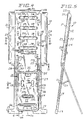
- Figure 3 is an enlarged front elevational view of the easel embodying the invention shown in Figure 1.
- Figure 4 is a rear elevational view of the easel shown in Figure 3, with parts of the upper easel section being broken away.
- Figure 5 is a side elevational view of the easel shown in Figure 3, with the legs extended.
- Figure 6 is a sectional view of the pedestal base portion of the easel taken on line 6 - 6 of Figure 4.
- Figure 7 is another sectional view of the pedestal base portion of the easel taken on line 7 - 7 of Figure 4.
- Figure 8a is a sectional view of the easel taken
on
line 8a - 8a of Figure 4. - Figure 8b is a sectional view of the easel taken
on line 8b - 8b of Figure 4, said line being a continuation
of
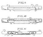
line 8a - 8a (without the pad clamp). - Figure 9 is a top plan view of the easel shown in Figure 4 (without the pad clamp).
- Figure 10 is a sectional view of the easel taken on line 10 - 10 of Figure 4.
- Figure 11 is a view of the easel taken on line 11 - 11 of Figure 4, taken partially in section.
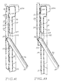
- Figure 12 is a detail sectional view of the leg locking structure for the easel when collapsed for table top use as shown in Figure 2.
- Figure 13 is a detail sectional view of the leg locking structure similar to Figure 12, except showing the easel in extended position of Figure 5, taken on line 13-13 thereof.
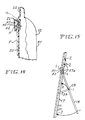
- Figure 14 is a fractional detail sectional view of the upper part of the display portion of the easel, showing the pad clamp and associated spring clip structure.
- Figure 15 is a detail schematic view of the toggle and leg movement relative to the pedestal base portion of the easel.
-
- With reference to Figures 1 - 5 of the accompanying drawings, the
easel 10 has a pedestal base portion 11 and adisplay portion 12, upon which a pad of paper P may be affixed or indicia placed thereon for display to a group of people in a conference or meeting situation. - Preferably, the pedestal base portion 11 has spaced apart
feet 13 andupright members 14, which may be bridged by the upper portion thereof definingcompartments 15 for holding markers, tape and the like. Telescoped into the pedestal base portion 11, is thedisplay portion 12, and this pedestal base portion has unitary front and rear walls, 16 and 17, respectively (see Figs. 6 and 7).Legs 18 are arranged and foldable intocorresponding grooves 19 on therear wall 17 of the pedestal base portion 11. - A
flat display board 20 is on one face of thedisplay portion 12, and is intended to back up a writing pad P or other display. Aspring clamp assembly 21 is secured to an upper edge of thedisplay board 20 so that a pad P may be clipped by the spring clamp assembly to thedisplay board 20 for securing the pad P thereon in a way for pages of the pad to be flipped over thetop 22 of the board.Lifting handles 23 may be molded intoside edges 24 of thedisplay portion 12 for easy and balanced lifting and collapsing of the display portion relative to the pedestal base portion 11. - The
legs 18 are preferably tubular and U-shaped and have abottom member 25 bridgingupright side members 26 which are pivotally secured to therear wall 17 of the pedestal base portion 11 by means of upper toggle bracket assemblies 27 throughshort toggle links 27a, preferably screw mounted to the rear wall and leg. Theside leg members 26 also are secured to therear wall 17 by lower toggle bracket assemblies 28, preferably also screw mounted to the rear wall and leg, throughlong toggle links 29, which define arcs for moving thelegs 18 toward and away from the pedestal base portion 11 during set up and storage of theeasel 10, as shown schematically in Figure 15, which depict the movement of the legs from position 1 toposition 2, and vice versa, in the direction of the respective arrows, as theleg ends 51 are articulated into and out of theapertures 52, in a manner and for a purpose hereafter discussed. Preferably, theleg side members 26 have anintegral cross member 30 at the connection of thetoggle links 29 to provide rigidity of the structure when set up. - The
rear wall 17 of the pedestal base has several recess and protrusions.Recesses 31 provide handles for carrying theeasel 10 selectively from either side of the easel when collapsed.Recess 32 provides a handle for carrying the easel by theleg cross member 30 in an upright position when collapsed.Recess 33 provides rigidity to the pedestal base portion 11 and includes kiss-offs or stress absorbing wells 33a for absorbing strain during collapse and extension of the display portion relative to the base portion.Bottom Recess 34 may be used for grasping thelegs 18 and pulling them out of the leg recesses during set up. Legcross member protrusions 35 act as guides for properly seating theleg cross member 30 when the legs are closed against the pedestal base portion in theleg recesses 19. Arounded protrusion 36 having an inverted V shaped cross section is arranged across the lower side of the rear wall and reinforces thewall 17. - With reference to the
display portion 12, itsrear wall 37 is unitary with the front wall forming thedisplay board 20, the rear wall has a plurality ofribs 38 andstress absorbing wells 39, which stiffen and space apart thefront display board 20 andrear wall 37 and absorb stress during extension and collapse of the base anddisplay portions 11 and 12, respectively. On each side of and between theribs 38, are a plurality oframps 40 which when. the easel is assembled preferably have a steeper taper in the direction of thefeet 13 and a relatively more shallow taper in the direction of the top of the display board, and below each of theseramps 40 is a stress absorbing well 41. - A
ledge 43 may be provided on the bottom edge of thedisplay board 20 which can act as a lip for balancing a marker when theeasel 10 is in use, and thisledge 43 also interlocks withrounded protrusion 36 on therear wall 17 of the pedestal base portion 11 when collapsed; and the upper face of theboard top 22 has arecess 42 which corresponds to a protrusion 43a on therear wall 17 of the pedestal base portion 11. Thus, like easels can be stacked interlocked and be retained in a stack while being transported. - The
spring clamp assembly 21 is preferably screw mounted to the front wall of thedisplay board 20 and may haveposts 44 having free ends over which drilled holes H in the pad are installed, and this assembly preferably comprises an inverted L shapedclamp plate 45 arranged over the face of theboard 20 for holding the upper edge of the pad P and abacker strip 46 which has a spring 47 urging theplate 45 over the pad toward thestrip 46. - As shown in Figure 9 - 11, the
rear wall 37 of thedisplay portion 12 is formed with spaced apart vertically arrangedtracks 48 andridges 49, and the pedestal base portion 11 hasinside edge member 50 formed corresponding to and interlocking with thetracks 48 andridges 49 for sliding thedisplay portion 12 upwardly or downwardly along theinside edge members 50 relative to thedisplay portion 12 for elevating or lower the display portion. - With reference to Figures 12 and 13, means is provided for securing the
display portion 12 relative to the pedestal base portion 11, either in extended floor mounted position as shown in Figure 1 or in telescoped table mounted position shown in Figure 2, respectively. In either position, thelegs 18 are articulated, by thetoggle links lower brackets leg side members 26 obliquely extend through anaperture 52 through the pedestal base portion 11 and come to rest against an angularly taperedwall 53 of the aperture clearingupper wall 54. - The
rear wall 37 of the display portion 11 has formed in it two sets of wedge shaped notches, one set arranged near the top 55 and the other set arranged near the bottom 56 of the display portionrear wall 37, each vertically and horizontally aligned, for receiving the leg ends 51, thus locking the display portion relative to the base portion selectively in the table top position shown in Figure 12 (using the top set 55 of notches) or the floor position shown in Figure 13 (using the bottom set 56 of notches). - In addition to the
ramps 40 previously described for slowing down the movement of thedisplay portion 12 as it slides downwardly on the pedestal base portion 11, bars 57 are formed on thefront wall 16 of the base portion, above theapertures 52, and correspondingbumps 58 are formed in therear wall 37 of the display portion to restrict the movement of thedisplay portion 12 downwardly on the base portion 11 and to help hold the portions in position once adjusted, as shown in Figures 12 and 13. - Also, when the
display portion 12 is telescoped downwardly over the base pedestal portion 11 in the manner described, thecompartments 15 are closed and covered by the display portion. Thus, materials stored in these compartments may be safely stored, transported and reused when the easel are needed again. - Normally, easels 10 are stored in the position shown in Figure 2, except the
legs 18 are folded against theleg recess 19, laid horizontally stacked one easel upon the next easel, so that they interlock, as described, for stability. The upper easel is removed from the pile, and itsdisplay portion 12 may be extended, as shown in Figure 1, if used on a floor, or telescoped, if used on a table, as shown in Figure 2, with the legs folded away from the pedestal base 11 and in interlocked position with thedisplay portion 12, as shown in Figures 12 and 13, respectively. A change from floor mount to table mount, or vice versa, may be easily accomplished, by slightly folding the leg ends 51 to clear thenotches board 20 upwardly or downwardly, and re-locking the leg ends into the corresponding notches. - The present invention is not limited to the specific embodiment described above. Alternative arrangements and suitable materials will be apparent to a reader skilled in the art.
Claims (14)
- A portable easel (10) comprising: a base pedestal portion (11) having leg means (18) pivotally mounted on and foldable toward and away from said base pedestal portion (11) for securing said base pedestal portion (11) upright on a surface; a display portion (12) telescopically engaged with said base pedestal portion (11) and having means (21) for removably securing thereon display materials; said portions (11,12) being movable relative to one another into extended and collapsed positions; said portions (11,12) having cooperating interlocking means for securing said portions in one of a plurality of selected positions when said leg means are pivoted and folded away from said base pedestal portion; characterised in that said interlocking means has an aperture (52) through said pedestal base portion (11) and notches (55,56) aligned with said aperture (52) in said display portion (12), and articulating means for moving a part (51) of said leg means (18) through said aperture (52) and into a corresponding notch to secure said portions (11,12) in selected position.
- The easel recited in claim 1, wherein at least one of said portions (11,12) is hollow, said hollow portion preferably having rib (33,38) and well means (33a, 39) to reinforce said portion, and wherein said portions are each preferably formed of unitary blow molded plastics material.
- The easel recited in claim 1 or claim 2, wherein said portions (11,12) have members (36,42,43,43a) adapted to interlock like easels, one stacked upon another easel for transportation and storage, said interlock stacking means preferably comprising a plurality of protrusions (43,43a) and recesses (36,42) on the faces of said portions (11,12).
- The easel recited in any preceding claim, wherein said leg means (18) comprise a U-shaped leg member pivotally secured and nested in a groove (19) in said base pedestal portion (11), said pivotal securement preferably comprising toggle bracket assemblies (27,28) joining said leg member to said base pedestal portion.
- The easel recited in claim 4, wherein said toggle bracket assemblies (27,28) define articulating arcs for the movement of said interlocking means.
- The easel recited in any preceding claim, wherein one or more of said base pedestal portion (11) and said leg means (18) has handle means (31,32), preferably integral handle means, which may be grasped when said easel (10) is in collapsed condition.
- The easel recited in any preceding claim, wherein said display portion (12) has a flat board surface (20) on a side opposed to the leg means (18) on said base pedestal portion (11), the edges (24) of said display portion (12) intermediate said board surface (20) preferably having opposed gripping handles (23) for telescoping said portions (11,12) into extended and collapsed condition.
- The easel recited in claim 7, wherein one edge of said board surface (20) has a clamp assembly (21) for securing display materials to said surface (20), said clamp assembly (21) preferably having a post element (44) for securing a drilled pad to said board surface (20) or a clip member arranged over a backer strip (46) sandwiched over said board surface (20) for holding said display material in position, a spring member (47) preferably being interspaced between said clip member and backer strip for urging said clip member against said board surface (20).
- The easel recited in any preceding claim, wherein said pedestal base portion (11) has integral compartments (15) which are open when said portions (11,12) are extended and closed when said portions (11,12) are in collapsed position.
- A portable easel (10) comprising: a base pedestal portion (11) having a face defining track means (50) for receiving a display portion (12) telescoped therein; a display portion (12) having a flat surface (20) for receiving indicia thereon and a surface remote from said flat surface (20) interlocked with and telescopically movable on said base pedestal track means (50); said portions (11,12) being telescopically movable relative to one another into extended and collapsed positions; cooperating interlocking means for securing said portions (11,12) in one of a plurality of selected positions; characterised in that said easel (10) further comprises ramp and bar means (40,57) restricting movement of said display portion (12) relative to said base pedestal portion (11) during movement of said portions (11, 12) in one direction but which do not interfere with movement in an opposite direction.
- The easel recited in claim 10 further comprising leg means (18) for holding said easel (10) upright in selected extended or collapsed position, wherein said leg means (18) are associated with said interlocking means and removably secure said portions (11,12) together when in selected position.
- A portable easel (10) comprising: a base pedestal portion (11) having leg means (18) pivotally mounted on and foldable toward and away from said base pedestal portion (11) for securing said base pedestal portion (11) upright on a surface; a display portion (12) telescopically engaged with said base pedestal portion (11) and having means (21) for removably securing thereon display materials; said portions (11,12) being movable relative to one another into extended and collapsed positions; cooperating interlocking means for securing said portions (11,12) in one of a plurality of selected positions; characterised in that said base portion (11) has a groove (19) for receiving said leg means (18) nested within the peripheral plane of said base portion (11) when said leg means (18) are folded against said base portion (11); said leg means (18) when extended having means for holding said base and display portions positioned in said one of the plurality of selected positions.
- The easel recited in claim 12, wherein said leg means (18) comprise a U-shaped leg member pivotally secured and nested in said groove (19), said pivotal securement preferably comprising toggle bracket assemblies (27,28) joining said leg member to said base pedestal portion (11).
- The easel recited in claim 13, wherein said toggle bracket assemblies (27,28) define articulating arcs for the movement of said interlocking means.
Priority Applications (1)
| Application Number | Priority Date | Filing Date | Title |
|---|---|---|---|
| EP01100016A EP1093736B1 (en) | 1993-06-09 | 1994-05-25 | Portable easel |
Applications Claiming Priority (2)
| Application Number | Priority Date | Filing Date | Title |
|---|---|---|---|
| US7473393A | 1993-06-09 | 1993-06-09 | |
| US74733 | 1993-06-09 |
Related Child Applications (1)
| Application Number | Title | Priority Date | Filing Date |
|---|---|---|---|
| EP01100016A Division EP1093736B1 (en) | 1993-06-09 | 1994-05-25 | Portable easel |
Publications (3)
| Publication Number | Publication Date |
|---|---|
| EP0628267A2 EP0628267A2 (en) | 1994-12-14 |
| EP0628267A3 EP0628267A3 (en) | 1997-05-21 |
| EP0628267B1 true EP0628267B1 (en) | 2002-03-13 |
Family
ID=22121352
Family Applications (2)
| Application Number | Title | Priority Date | Filing Date |
|---|---|---|---|
| EP01100016A Expired - Lifetime EP1093736B1 (en) | 1993-06-09 | 1994-05-25 | Portable easel |
| EP94303760A Expired - Lifetime EP0628267B1 (en) | 1993-06-09 | 1994-05-25 | Portable easel |
Family Applications Before (1)
| Application Number | Title | Priority Date | Filing Date |
|---|---|---|---|
| EP01100016A Expired - Lifetime EP1093736B1 (en) | 1993-06-09 | 1994-05-25 | Portable easel |
Country Status (3)
| Country | Link |
|---|---|
| EP (2) | EP1093736B1 (en) |
| AT (1) | ATE214245T1 (en) |
| DE (2) | DE69430084D1 (en) |
Cited By (1)
| Publication number | Priority date | Publication date | Assignee | Title |
|---|---|---|---|---|
| DE10260587A1 (en) * | 2002-12-21 | 2004-07-15 | Jakob Maul Gmbh | Flipchart is guided on fixed guide elements of stand legs, and has a fixing mechanism which is formed of a clamp |
Families Citing this family (1)
| Publication number | Priority date | Publication date | Assignee | Title |
|---|---|---|---|---|
| US6889952B2 (en) | 2001-11-02 | 2005-05-10 | Boone International, Inc. | Multi-position presentation easel |
Family Cites Families (10)
| Publication number | Priority date | Publication date | Assignee | Title |
|---|---|---|---|---|
| US2680932A (en) | 1954-06-15 | Foldable painter s outfit | ||
| US3195849A (en) | 1964-01-02 | 1965-07-20 | Robert B Maddox Associates Inc | Easel construction |
| US3512486A (en) * | 1968-02-01 | 1970-05-19 | Felix P Blanchard | Combined folding ironing board,table,drawing board and easel |
| GB1396310A (en) * | 1971-05-14 | 1975-06-04 | Cobworth Ltd | Easels |
| US4042203A (en) * | 1975-10-07 | 1977-08-16 | Warkentin Verona D | Easel |
| FR2484226B1 (en) * | 1980-06-11 | 1986-11-07 | Mourin Remy | EASEL TABLE |
| GB2119645B (en) * | 1982-05-11 | 1985-08-14 | Masters Wilkerson Manufacturin | Backing for a photo or picture frame |
| DE3940350A1 (en) * | 1988-12-14 | 1990-06-21 | Artec Design Gmbh | Display board made of hinged section - folds into box shape, containing tripod stand, marking pens and other accessories |
| US5088678A (en) * | 1990-07-25 | 1992-02-18 | Nachum Bitan | Multi-station easel |
| US5152490A (en) * | 1991-08-16 | 1992-10-06 | Pierce Companies, Inc. | Display easel with self-adjusting paper clamp |
-
1994
- 1994-05-25 AT AT94303760T patent/ATE214245T1/en not_active IP Right Cessation
- 1994-05-25 DE DE69430084T patent/DE69430084D1/en not_active Expired - Lifetime
- 1994-05-25 EP EP01100016A patent/EP1093736B1/en not_active Expired - Lifetime
- 1994-05-25 DE DE60124795T patent/DE60124795D1/en not_active Expired - Lifetime
- 1994-05-25 EP EP94303760A patent/EP0628267B1/en not_active Expired - Lifetime
Cited By (1)
| Publication number | Priority date | Publication date | Assignee | Title |
|---|---|---|---|---|
| DE10260587A1 (en) * | 2002-12-21 | 2004-07-15 | Jakob Maul Gmbh | Flipchart is guided on fixed guide elements of stand legs, and has a fixing mechanism which is formed of a clamp |
Also Published As
| Publication number | Publication date |
|---|---|
| EP0628267A3 (en) | 1997-05-21 |
| ATE214245T1 (en) | 2002-03-15 |
| EP0628267A2 (en) | 1994-12-14 |
| EP1093736A3 (en) | 2001-08-16 |
| DE69430084D1 (en) | 2002-04-18 |
| EP1093736A2 (en) | 2001-04-25 |
| EP1093736B1 (en) | 2006-03-22 |
| DE60124795D1 (en) | 2007-01-11 |
Similar Documents
| Publication | Publication Date | Title |
|---|---|---|
| US5478040A (en) | Portable easel | |
| US6732663B2 (en) | Foldable table | |
| US6912961B2 (en) | Personal table | |
| US8156875B2 (en) | Handle for a portable table | |
| US20220117393A1 (en) | Storage system | |
| US20060254480A1 (en) | Multi-shelf collapsible table | |
| US11963595B2 (en) | Multipurpose bag table apparatus | |
| US20040182290A1 (en) | Personal table | |
| US20170312909A1 (en) | Sawhorse | |
| US6877441B2 (en) | Foldable table | |
| CA2274443A1 (en) | Collapsible portable work support | |
| EP1093736B1 (en) | Portable easel | |
| US20060191447A1 (en) | Table with drawer | |
| WO1987003461A1 (en) | Kneeling aid | |
| AU700469B2 (en) | Portable easel | |
| US20230329404A1 (en) | Multipurpose bag apparatus | |
| US20060055291A1 (en) | Collapsible bar | |
| GB2340390A (en) | Folding book support | |
| US6928934B2 (en) | Foldable table with four bar link | |
| GB2105683A (en) | Collapsible container | |
| AU2003273580B2 (en) | Personal table | |
| WO2008003998A1 (en) | Foldable table | |
| GB2086219A (en) | A foldable music stand | |
| AU571790B2 (en) | Kneeling aid | |
| WO2003059119A2 (en) | Personal table |
Legal Events
| Date | Code | Title | Description |
|---|---|---|---|
| PUAI | Public reference made under article 153(3) epc to a published international application that has entered the european phase |
Free format text: ORIGINAL CODE: 0009012 |
|
| AK | Designated contracting states |
Kind code of ref document: A2 Designated state(s): AT BE CH DE DK ES FR GB GR IE IT LI LU MC NL PT SE |
|
| PUAL | Search report despatched |
Free format text: ORIGINAL CODE: 0009013 |
|
| AK | Designated contracting states |
Kind code of ref document: A3 Designated state(s): AT BE CH DE DK ES FR GB GR IE IT LI LU MC NL PT SE |
|
| 17P | Request for examination filed |
Effective date: 19971107 |
|
| 17Q | First examination report despatched |
Effective date: 19990518 |
|
| GRAG | Despatch of communication of intention to grant |
Free format text: ORIGINAL CODE: EPIDOS AGRA |
|
| GRAG | Despatch of communication of intention to grant |
Free format text: ORIGINAL CODE: EPIDOS AGRA |
|
| GRAH | Despatch of communication of intention to grant a patent |
Free format text: ORIGINAL CODE: EPIDOS IGRA |
|
| GRAH | Despatch of communication of intention to grant a patent |
Free format text: ORIGINAL CODE: EPIDOS IGRA |
|
| REG | Reference to a national code |
Ref country code: GB Ref legal event code: IF02 |
|
| GRAA | (expected) grant |
Free format text: ORIGINAL CODE: 0009210 |
|
| AK | Designated contracting states |
Kind code of ref document: B1 Designated state(s): AT BE CH DE DK ES FR GB GR IE IT LI LU MC NL PT SE |
|
| PG25 | Lapsed in a contracting state [announced via postgrant information from national office to epo] |
Ref country code: NL Free format text: LAPSE BECAUSE OF FAILURE TO SUBMIT A TRANSLATION OF THE DESCRIPTION OR TO PAY THE FEE WITHIN THE PRESCRIBED TIME-LIMIT Effective date: 20020313 Ref country code: LI Free format text: LAPSE BECAUSE OF FAILURE TO SUBMIT A TRANSLATION OF THE DESCRIPTION OR TO PAY THE FEE WITHIN THE PRESCRIBED TIME-LIMIT Effective date: 20020313 Ref country code: IT Free format text: LAPSE BECAUSE OF FAILURE TO SUBMIT A TRANSLATION OF THE DESCRIPTION OR TO PAY THE FEE WITHIN THE PRESCRIBED TIME-LIMIT;WARNING: LAPSES OF ITALIAN PATENTS WITH EFFECTIVE DATE BEFORE 2007 MAY HAVE OCCURRED AT ANY TIME BEFORE 2007. THE CORRECT EFFECTIVE DATE MAY BE DIFFERENT FROM THE ONE RECORDED. Effective date: 20020313 Ref country code: GR Free format text: LAPSE BECAUSE OF FAILURE TO SUBMIT A TRANSLATION OF THE DESCRIPTION OR TO PAY THE FEE WITHIN THE PRESCRIBED TIME-LIMIT Effective date: 20020313 Ref country code: FR Free format text: LAPSE BECAUSE OF FAILURE TO SUBMIT A TRANSLATION OF THE DESCRIPTION OR TO PAY THE FEE WITHIN THE PRESCRIBED TIME-LIMIT Effective date: 20020313 Ref country code: CH Free format text: LAPSE BECAUSE OF FAILURE TO SUBMIT A TRANSLATION OF THE DESCRIPTION OR TO PAY THE FEE WITHIN THE PRESCRIBED TIME-LIMIT Effective date: 20020313 Ref country code: BE Free format text: LAPSE BECAUSE OF FAILURE TO SUBMIT A TRANSLATION OF THE DESCRIPTION OR TO PAY THE FEE WITHIN THE PRESCRIBED TIME-LIMIT Effective date: 20020313 Ref country code: AT Free format text: LAPSE BECAUSE OF FAILURE TO SUBMIT A TRANSLATION OF THE DESCRIPTION OR TO PAY THE FEE WITHIN THE PRESCRIBED TIME-LIMIT Effective date: 20020313 |
|
| REF | Corresponds to: |
Ref document number: 214245 Country of ref document: AT Date of ref document: 20020315 Kind code of ref document: T |
|
| REG | Reference to a national code |
Ref country code: CH Ref legal event code: EP |
|
| REF | Corresponds to: |
Ref document number: 69430084 Country of ref document: DE Date of ref document: 20020418 |
|
| PG25 | Lapsed in a contracting state [announced via postgrant information from national office to epo] |
Ref country code: MC Free format text: LAPSE BECAUSE OF NON-PAYMENT OF DUE FEES Effective date: 20020525 Ref country code: LU Free format text: LAPSE BECAUSE OF NON-PAYMENT OF DUE FEES Effective date: 20020525 |
|
| PG25 | Lapsed in a contracting state [announced via postgrant information from national office to epo] |
Ref country code: IE Free format text: LAPSE BECAUSE OF NON-PAYMENT OF DUE FEES Effective date: 20020527 |
|
| PG25 | Lapsed in a contracting state [announced via postgrant information from national office to epo] |
Ref country code: SE Free format text: LAPSE BECAUSE OF FAILURE TO SUBMIT A TRANSLATION OF THE DESCRIPTION OR TO PAY THE FEE WITHIN THE PRESCRIBED TIME-LIMIT Effective date: 20020613 Ref country code: DK Free format text: LAPSE BECAUSE OF FAILURE TO SUBMIT A TRANSLATION OF THE DESCRIPTION OR TO PAY THE FEE WITHIN THE PRESCRIBED TIME-LIMIT Effective date: 20020613 |
|
| PG25 | Lapsed in a contracting state [announced via postgrant information from national office to epo] |
Ref country code: PT Free format text: LAPSE BECAUSE OF FAILURE TO SUBMIT A TRANSLATION OF THE DESCRIPTION OR TO PAY THE FEE WITHIN THE PRESCRIBED TIME-LIMIT Effective date: 20020614 Ref country code: DE Free format text: LAPSE BECAUSE OF FAILURE TO SUBMIT A TRANSLATION OF THE DESCRIPTION OR TO PAY THE FEE WITHIN THE PRESCRIBED TIME-LIMIT Effective date: 20020614 |
|
| NLV1 | Nl: lapsed or annulled due to failure to fulfill the requirements of art. 29p and 29m of the patents act | ||
| REG | Reference to a national code |
Ref country code: CH Ref legal event code: PL |
|
| PG25 | Lapsed in a contracting state [announced via postgrant information from national office to epo] |
Ref country code: ES Free format text: LAPSE BECAUSE OF FAILURE TO SUBMIT A TRANSLATION OF THE DESCRIPTION OR TO PAY THE FEE WITHIN THE PRESCRIBED TIME-LIMIT Effective date: 20020925 |
|
| EN | Fr: translation not filed | ||
| PLBE | No opposition filed within time limit |
Free format text: ORIGINAL CODE: 0009261 |
|
| STAA | Information on the status of an ep patent application or granted ep patent |
Free format text: STATUS: NO OPPOSITION FILED WITHIN TIME LIMIT |
|
| 26N | No opposition filed |
Effective date: 20021216 |
|
| REG | Reference to a national code |
Ref country code: IE Ref legal event code: MM4A |
|
| PGFP | Annual fee paid to national office [announced via postgrant information from national office to epo] |
Ref country code: GB Payment date: 20060524 Year of fee payment: 13 |
|
| GBPC | Gb: european patent ceased through non-payment of renewal fee |
Effective date: 20070525 |
|
| PG25 | Lapsed in a contracting state [announced via postgrant information from national office to epo] |
Ref country code: GB Free format text: LAPSE BECAUSE OF NON-PAYMENT OF DUE FEES Effective date: 20070525 |