EP0627332A1 - Tyre for motor-vehicle wheels provided with a tread producing a low rolling noise - Google Patents
Tyre for motor-vehicle wheels provided with a tread producing a low rolling noise Download PDFInfo
- Publication number
- EP0627332A1 EP0627332A1 EP94107942A EP94107942A EP0627332A1 EP 0627332 A1 EP0627332 A1 EP 0627332A1 EP 94107942 A EP94107942 A EP 94107942A EP 94107942 A EP94107942 A EP 94107942A EP 0627332 A1 EP0627332 A1 EP 0627332A1
- Authority
- EP
- European Patent Office
- Prior art keywords
- cuts
- tread
- rows
- tyre according
- equatorial plane
- Prior art date
- Legal status (The legal status is an assumption and is not a legal conclusion. Google has not performed a legal analysis and makes no representation as to the accuracy of the status listed.)
- Granted
Links
Images

Classifications
-
- B—PERFORMING OPERATIONS; TRANSPORTING
- B60—VEHICLES IN GENERAL
- B60C—VEHICLE TYRES; TYRE INFLATION; TYRE CHANGING; CONNECTING VALVES TO INFLATABLE ELASTIC BODIES IN GENERAL; DEVICES OR ARRANGEMENTS RELATED TO TYRES
- B60C11/00—Tyre tread bands; Tread patterns; Anti-skid inserts
- B60C11/03—Tread patterns
- B60C11/0302—Tread patterns directional pattern, i.e. with main rolling direction
-
- B—PERFORMING OPERATIONS; TRANSPORTING
- B60—VEHICLES IN GENERAL
- B60C—VEHICLE TYRES; TYRE INFLATION; TYRE CHANGING; CONNECTING VALVES TO INFLATABLE ELASTIC BODIES IN GENERAL; DEVICES OR ARRANGEMENTS RELATED TO TYRES
- B60C11/00—Tyre tread bands; Tread patterns; Anti-skid inserts
- B60C11/03—Tread patterns
- B60C11/0306—Patterns comprising block rows or discontinuous ribs
-
- B—PERFORMING OPERATIONS; TRANSPORTING
- B60—VEHICLES IN GENERAL
- B60C—VEHICLE TYRES; TYRE INFLATION; TYRE CHANGING; CONNECTING VALVES TO INFLATABLE ELASTIC BODIES IN GENERAL; DEVICES OR ARRANGEMENTS RELATED TO TYRES
- B60C11/00—Tyre tread bands; Tread patterns; Anti-skid inserts
- B60C11/03—Tread patterns
- B60C11/0318—Tread patterns irregular patterns with particular pitch sequence
-
- B—PERFORMING OPERATIONS; TRANSPORTING
- B60—VEHICLES IN GENERAL
- B60C—VEHICLE TYRES; TYRE INFLATION; TYRE CHANGING; CONNECTING VALVES TO INFLATABLE ELASTIC BODIES IN GENERAL; DEVICES OR ARRANGEMENTS RELATED TO TYRES
- B60C11/00—Tyre tread bands; Tread patterns; Anti-skid inserts
- B60C11/03—Tread patterns
- B60C2011/0337—Tread patterns characterised by particular design features of the pattern
- B60C2011/0339—Grooves
- B60C2011/0374—Slant grooves, i.e. having an angle of about 5 to 35 degrees to the equatorial plane
-
- B—PERFORMING OPERATIONS; TRANSPORTING
- B60—VEHICLES IN GENERAL
- B60C—VEHICLE TYRES; TYRE INFLATION; TYRE CHANGING; CONNECTING VALVES TO INFLATABLE ELASTIC BODIES IN GENERAL; DEVICES OR ARRANGEMENTS RELATED TO TYRES
- B60C11/00—Tyre tread bands; Tread patterns; Anti-skid inserts
- B60C11/03—Tread patterns
- B60C2011/0337—Tread patterns characterised by particular design features of the pattern
- B60C2011/0339—Grooves
- B60C2011/0381—Blind or isolated grooves
- B60C2011/0383—Blind or isolated grooves at the centre of the tread
-
- Y—GENERAL TAGGING OF NEW TECHNOLOGICAL DEVELOPMENTS; GENERAL TAGGING OF CROSS-SECTIONAL TECHNOLOGIES SPANNING OVER SEVERAL SECTIONS OF THE IPC; TECHNICAL SUBJECTS COVERED BY FORMER USPC CROSS-REFERENCE ART COLLECTIONS [XRACs] AND DIGESTS
- Y10—TECHNICAL SUBJECTS COVERED BY FORMER USPC
- Y10S—TECHNICAL SUBJECTS COVERED BY FORMER USPC CROSS-REFERENCE ART COLLECTIONS [XRACs] AND DIGESTS
- Y10S152/00—Resilient tires and wheels
- Y10S152/03—Slits in threads
-
- Y—GENERAL TAGGING OF NEW TECHNOLOGICAL DEVELOPMENTS; GENERAL TAGGING OF CROSS-SECTIONAL TECHNOLOGIES SPANNING OVER SEVERAL SECTIONS OF THE IPC; TECHNICAL SUBJECTS COVERED BY FORMER USPC CROSS-REFERENCE ART COLLECTIONS [XRACs] AND DIGESTS
- Y10—TECHNICAL SUBJECTS COVERED BY FORMER USPC
- Y10S—TECHNICAL SUBJECTS COVERED BY FORMER USPC CROSS-REFERENCE ART COLLECTIONS [XRACs] AND DIGESTS
- Y10S152/00—Resilient tires and wheels
- Y10S152/903—Non-directional tread pattern having non-circumferential transverse groove following smooth curved path
Definitions
- the present invention relates to a tyre for motor-vehicle wheels provided with a tread producing a low rolling noise, which comprises a raised pattern formed of a plurality of shaped blocks distributed in parallel circumferential rows bounded by longitudinal grooves extending circumferentially of the tyre and each comprising a given number of shaped blocks separated from each other by respective transverse cuts.
- tyres for road motor-vehicles have a plurality of longitudinal grooves and transverse cuts on the tread, which define a plurality of shaped blocks thereon, said blocks being distributed according to a specific pattern suitably studied.
- the longitudinal grooves by effect of which the shaped blocks are distributed in several side by side rows, give the tyre the desired features of directional control stability and roadholding in relation to the drift thrusts directed parallelly of the wheel axis.
- the transverse cuts in turn, give the tyre the desired tractive features, that is the capability of efficiently transmitting the tangential thrusts parallel to the running direction during the speeding up and slowing down steps of the vehicle.
- the tractive power of the tyre tends to become greater as the number of the transverse cuts arranged in the tread increases and the orientation of the cuts themselves approaches the perpendicular to the running direction.
- longitudinal grooves and transverse cuts cooperate in performing an efficient draining action of the water from the imprinting area of the tyre during the running on a wet road-bed.
- the dynamic actions causing the deformation of the tread between the entry and exit regions to and from the imprinting area also give rise to a cyclic volumetric variation of the grooves and cuts defined between the shaped blocks, which brings about a cyclic compressive and decompressive action on the air contained in the grooves and cuts.
- One expedient which as been adopted for a long time essentially consists in differentiating the longitudinal dimensions, that is those along the circumferential extension, of the single shaped blocks.
- the blocks are disposed on the circumferential extension of the tread according to two or more differentiated pitch values distributed in a circumferential succession, usually referred to as "pitch sequence" which is generally studied so as to achieve the maximum possible unevenness over the whole circumferential extension.
- pitch sequence which is generally studied so as to achieve the maximum possible unevenness over the whole circumferential extension.
- the pressure waves generated by the impacts and rubbings of the blocks do not take place according to a specific frequency on which most of the acoustic energy generated as a result of rolling would be concentrated.
- the acoustic energy is distributed over a wide frequency range, thereby eliminating the troublesome effect of noise usually known as "squirrel effect”.
- Another expedient consists in giving the transverse cuts a suitably inclined orientation with respect to the perpendicular to the running direction. This enables the impacts of the block corners on the road-bed to be “smoothed" but, on the other hand, it impairs the tractive features of the tyre.
- sipes in the shaped blocks, said sipes being adapted to increase the elastic deformability of the blocks.
- This solution too enables the impact of the block on the road-bed to be smoothed, thereby causing a reduction of the noise resulting from impacts.
- the greater deformability of a block will tend to increase the noise effects resulting from rubbings.
- the invention relates to a tyre for vehicle wheels, in particular motor-vehicle wheels, provided with a tread producing a low rolling noise, characterized in that each of said rows has an amount of shaped blocks greater than the amount of shaped blocks present in the row disposed consecutively in side by side relation therewith towards the equatorial plane of the tread, in order to give the tread a gradually increasing longitudinal stiffness from the outer side edges thereof towards said equatorial plane.
- At least one continuous circumferential rib may be disposed, said rib being delimited between two of said longitudinal grooves.
- two of said circumferential ribs are provided and they are symmetrically disposed with respect to the equatorial plane of the tread and mutually separated by a central groove.
- the transverse cuts define an impact angle with the adjacent longitudinal grooves which has a greater width than the impact angle formed with the transverse cuts of the block row disposed consecutively in side by side relation therewith towards the equatorial plane.
- the value of the impact angle in the block rows that are closest to the equatorial plane is in the range of 15° to 25°, whereas in the block rows closest to the side edges of the tread said impact angle is in the range of 70° to 105°.
- each of said rows has first transverse cuts each extending consecutively of one of the first transverse cuts belonging to the block row disposed adjacently in side by side relation.
- Said first cuts consecutively aligned define continuous transverse grooves each extending from the corresponding outer side edge of the tread as far as close to said equatorial plane.
- Each of said transverse grooves starting from the corresponding outer side edge has one straight portion substantially perpendicular to the longitudinal grooves, a curved union portion and a second straight portion disposed obliquely relative to said longitudinal grooves.
- At least one of said block rows has second transverse cuts each of them being intermediate between two of said first cuts.
- the second cuts are associated with outer shoulder rows, adjacent to the outer side edges of the tread, and inner shoulder rows disposed side by side with the outer shoulder rows towards the equatorial plane.
- Each of said second cuts is spaced apart a varying distance from the first cuts contiguous therewith and has a lower width than the first cuts.
- the ratio between the width of the second cuts and that of the first cuts is in the range of 50% to 100%.
- the blocks of at least one of said rows should each have at least one transverse slot extending towards said equatorial plane over a portion of lower width than the width of the block itself, in the extension of one of said second cuts.
- Said transverse slots are preferentially associated with outer centre rows disposed consecutively and side by side with the inner shoulder rows towards the equatorial plane of the tread.
- Each of said transverse slots extends over about half the width of the respective block.
- At least one of said block rows further comprises third cuts extending parallel to said first and second transverse cuts.
- said third transverse cuts are associated with outer shoulder rows adjacent to the outer side edges of the tread.
- the longitudinal grooves separating the outer shoulder rows from the block rows contiguous thereto are interrupted in the portions included between each of the third cuts and one of the first and second contiguous cuts.
- the third cuts preferentially have a lower width than said first and second transverse cuts.
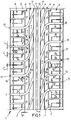
- a tread producing a low rolling noise in particular for motor-vehicle tyres in accordance with the present invention has been generally identified by reference numeral 1.
- the tread 1 conventionally has a plurality of longitudinal grooves 2, spaced apart a suitable distance from each other and extending in a circumferential direction relative to the tyre with which the tread is associated.
- Such grooves 2 define on the width of the tread 1, a plurality of circumferential rows 3, 4, 5, 6 disposed parallelly in side by side relation and extending circumferentially of the tyre and each comprising a given number of shaped blocks 7. 7a, 7b separated from each other by respective transverse cuts suitably oriented relative to the longitudinal grooves 2.
- each of the circumferential rows 3, 4, 5, 6 has an amount of shaped blocks 7, 7a, 7b greater than the amount of blocks present in the row disposed side by side and consecutive thereto towards the equatorial plane of the tread 1 denoted by line X-X in Fig. 1.
- the number of blocks 7, 7a, 7b present in each row 3, 4, 5, 6 gradually increases on passing from the central area towards the side edges 1a of the tread 1.
- This expedient enables the tread 1 to acquire a longitudinal stiffness gradually increasing from the outer side edges thereof towards the equatorial plane X-X, for the purposes to be clarified in the following.
- the number of blocks 7 be substantially zero, as at least one circumferential continuous rib 11 is located at said area, said rib being delimited between two of said longitudinal grooves 2.
- the presence of two circumferential ribs 11 disposed symmetrically of the equatorial plane X-X is preferably provided, said ribs being mutually separated by a centre groove 12 having substantially the same width as the individual ribs 11.
- each rib 11 Externally of each rib 11, that is moving away from the equatorial plane X-X, there is an inner central row 3, an outer central row 4, an inner shoulder row 5 and an outer shoulder row 6, said rows being disposed consecutively in side by side relation.
- Each of said rows 3, 4, 5, 6 has first transverse cuts 8 each of which, advantageously, consecutively faces one of the first transverse cuts 8 belonging to the adjacent row or rows of shaped blocks disposed in side by side relation therewith.
- the first transverse cuts 8 as a whole define continuous transverse grooves 13 each extending from the corresponding outer side edge 1a of the tread 1 until close to the equatorial plane X-X and more particularly until close to one of the circumferential ribs 11.
- This solution advantageously enables the width of the longitudinal grooves to be limited to advantage of the tractive features of the tyre, the water draining action during a running on a wet road-bed relying on the transverse grooves 13 that exhibit an extension substantially devoid of interruptions thus allowing the water to easily flow towards the outer side edges of the tread 1.
- the longitudinal grooves 2 have a lower width than the first transverse cuts 8 and the transverse grooves 13 generated by said transverse cuts 8.
- the ratio between the width "l" of the longitudinal grooves 2 and the width "L” of the first transverse cuts 8 is provided to be included between 0.6 and 0.2 and preferably corresponds to 0.4.
- each of the transverse grooves 13 starting from the corresponding side edge 1a should exhibit one straight portion substantially perpendicular to the longitudinal grooves 2 and extending close to the respective shoulder rows 5, 6, one curved union portion extending close to the outer central row 4 and a second straight portion disposed obliquely of the longitudinal grooves 2 and located close to the inner central raw 3.
- said straight portion in its axially outermost section that is the section decreasing towards the tyre sidewall, it can take an inclination greater than 90° relative to the equatorial plane of the tyre, even if said inclination preferably should not be higher than 105°.
- the impact angle " ⁇ " of the blocks 7 present in the different rows 3, 4, 5, 6 gradually increases from the equatorial plane X-X towards the outer side edges 1a of the tread.
- the value of the impact angle ⁇ in the inner central rows 3 closest to the equatorial plane X-X should be in the range of 15° to 25°, whereas the value of the impact angle ⁇ in the outer shoulder rows 6 closest to the side edges 1a of the tread 1 should be in the range of 70° to 105°.
- the value of the impact angle ⁇ gradually increases moving away from the equatorial plane X-X, from 20° at the inner centre rows 3, to 90° at the outer 6 and inner 5 shoulder rows.
- one or more of the block rows in the embodiment shown the outer 6 and inner 5 shoulder rows, should be provided with second transverse cuts 9 each of them being intermediate between the first cuts contiguous thereto and spaced apart a varying distance therefrom.
- the second transverse cuts 9 have a lower width "L'" than the first cuts 8. More particularly, the ratio between the width of the second cuts 9 and the width of the first cuts 8 is in the range of 50% to 100%, and preferably corresponds to approximately 70%.
- the ratio between the block number in two side by side block rows varies on varying of the number of the additional cuts (second transverse cuts 9) intermediate between the main cuts (first transverse cuts 8), so that said ratio can be made different from two, if convenient, by increasing or decreasing the number of said additional cuts, even in a different manner, between the different pairs of main cuts.
- Transverse slots 9a stretch out in the extension of the second cuts 9 in the blocks 7 belonging to the adjacent rows (in the case shown the outer centre rows 4) towards the equatorial plane X-X according to a portion of lower width than that of the corresponding blocks 7.
- each of the transverse slots 9a stretches out for about half the width of the respective block 7, according to an extension substantially parallel to that of the first cuts 8 bounding the block itself.
- the presence of the transverse cuts 9a in the blocks 7 belonging to the outer centre rows 4 causes the amount of blocks present in said rows to be virtually increased, to the ends of a good operation of the tyres, as far as the achievement of a value included between the amount of blocks generated in the outer centre rows 4 by the presence of the first cuts 8 and the amount of blocks generated in the inner shoulder rows 5 by the presence of the first and second cuts 8 and 9.
- One or more of the block rows, in the case shown the outer shoulder rows 6, are also provided with third transverse cuts 10 extending parallel to the first and second transverse cuts 8, 9 at a suitably spaced apart position therefrom.
- the presence of the third cuts 10 in each outer shoulder row 6 substantially doubles the number of blocks 7a, 7b already defined therein by the presence of the first and second cuts 8, 9.
- the number of blocks present in the inner centre row 3 must preferably be included between 40 blocks maximum and 20 blocks minimum.
- each of the outer shoulder rows 6 exhibits linked blocks 7a formed of one piece construction with the blocks 7 belonging to the adjacent inner shoulder row 5 alternating with free blocks 7b which are at least partly disengaged from said blocks 7.
- the third transverse cuts 10 preferably have a width L'' which is smaller than that of the first and second transverse cuts 8, 9.
- each of the third cuts 10 along its axial extension has an inner portion 10a facing the equatorial plane X-X the width of which is preferably lower than 1 mm and an outer portion the width of which is greater than that of the inner portion 10a.
- the first, second and third transverse cuts 8, 9, 10 are also provided to be distributed in such a manner that the blocks 7 defined on the circumferential extension of the tread 1 have differentiated sizes alternating in a predetermined sequence, usually referred to as "stepped sequence", so that the acoustic energy produced following the tyre rolling on the road-bed is distributed according to a wide frequency range.
- the distribution of the above described first, second and third transverse cuts 8, 9, 10 is such that it enables the number of the blocks 7 associated with the individual centre rows 3, 4 and shoulder rows 5, 6 to gradually increase moving away from the equatorial plane X-X towards the side edges 1a of the tread 1.
- Fig. 3 graphically shows the variation in the number of blocks 7 in the different rows 3, 4, 5, 6 defined on the tread width.
- the lines denoted by A, B, C, D E on the abscissa axis "a" correspond to width portions of the tread 1 comprised of the circumferential ribs 11, the inner centre rows 3, outer centre rows 4, inner shoulder rows 5 and outers shoulder rows 6.
- Numerically reproduced on the ordinate axis "b" are the amounts of the blocks arranged in the individual areas A, B, C, D, E, in relation to the number of the blocks provided in the inner centre rows 3 corresponding to areas B.
- the chain lines C' referred to areas C show the virtual amount of the blocks 7 detectable in the outer centre rows 4 by effect of the first cuts 8 and slots 9a.
- the longitudinal stiffness detectable at corresponding areas of the tread width varies correspondingly.
- a longitudinal stiffness gradually increases from the outer side edges 1a of the tread 1 towards the equatorial plane X-X, as far as its maximum value is reached at the circumferential ribs 11.
- the tread areas that are most liable to produce the outer noise are those closest to the equatorial plane X-X.
- the noise produced by rolling is particularly enhanced by rubbings and deformations undergone by the blocks during the transitory steps of contacts and separations with and from the road-bed at the contact area.
- Another contributory factor in generating rubbings is represented by the acceleration undergone by the blocks 7 during the contact and separation steps with and from the contact area.
- the value of such accelerations is a function of the square radius according to which the blocks 7 are distributed about the tyre axis, the blocks closer to the equatorial plane X-X are those that undergo the greatest acceleration in that the tread 1, as known, has a convex outer profile seen in cross-section.
- the smaller number of blocks in the centre areas of the tread 1 does not greatly impair the tractive features of the tyre. Said features in fact mostly rely on the great number of blocks 7, 7a, 7b arranged in the shoulder rows 5, 6 where the greatest contact pressure and smallest tendency to rubbing are found.
- the variation in the inclination of the transverse cuts 8 is advantageous for the purpose of reducing the outer rolling noise without jeopardizing the tractive features.
- the reduced angle " ⁇ " formed with the cuts 8 and longitudinal grooves 2 close to the centre rows 3, 4 greatly smooths the impact of the blocks 7 onto the ground, exactly at the areas on which the outer noise most depends.
- the cuts 8 take an orientation perpendicular to the longitudinal grooves 2 and therefore to the running direction at the areas close to the side edges where the outer noise effects are felt the least and the tractive features are of great importance.
- the tread pattern shown in Fig. 1 referring particularly to the transverse grooves, is symmetric but said tread may also have an asymmetric pattern or a pattern showing mirror images on the two sides of the equatorial plane X-X.
Abstract
Description
- The present invention relates to a tyre for motor-vehicle wheels provided with a tread producing a low rolling noise, which comprises a raised pattern formed of a plurality of shaped blocks distributed in parallel circumferential rows bounded by longitudinal grooves extending circumferentially of the tyre and each comprising a given number of shaped blocks separated from each other by respective transverse cuts.
- It is known that tyres for road motor-vehicles have a plurality of longitudinal grooves and transverse cuts on the tread, which define a plurality of shaped blocks thereon, said blocks being distributed according to a specific pattern suitably studied.
- Within said pattern the longitudinal grooves by effect of which the shaped blocks are distributed in several side by side rows, give the tyre the desired features of directional control stability and roadholding in relation to the drift thrusts directed parallelly of the wheel axis. The transverse cuts, in turn, give the tyre the desired tractive features, that is the capability of efficiently transmitting the tangential thrusts parallel to the running direction during the speeding up and slowing down steps of the vehicle. In principle, the tractive power of the tyre tends to become greater as the number of the transverse cuts arranged in the tread increases and the orientation of the cuts themselves approaches the perpendicular to the running direction.
- In addition, the longitudinal grooves and transverse cuts cooperate in performing an efficient draining action of the water from the imprinting area of the tyre during the running on a wet road-bed.
- The presence of the transverse cuts and longitudinal grooves however causes the well known effect of noise produced by the tyre rolling. In greater detail, one of the main causes of the rolling noise has been found in the continuous succession of impacts of the shaped block corners on the road-bed.
- Another contributory cause in generating noise is given by rubbings that the shaped blocks undergo in contact with the road-bed when they enter and leave the imprinting area. These rubbings are essentially due to the deformations necessarily undergone by the tread, in that its outer surface which in a free state has a convex conformation with a double bending, as known, inevitably becomes flat against the road-bed.
- The dynamic actions causing the deformation of the tread between the entry and exit regions to and from the imprinting area also give rise to a cyclic volumetric variation of the grooves and cuts defined between the shaped blocks, which brings about a cyclic compressive and decompressive action on the air contained in the grooves and cuts. These phenomena of air compression and decompression help in causing the generation of noise produced by the tyre rolling.
- The known art suggests several expedients for limiting the noise produced by the tyre rolling as much as possible.
- One expedient which as been adopted for a long time essentially consists in differentiating the longitudinal dimensions, that is those along the circumferential extension, of the single shaped blocks. In other words, the blocks are disposed on the circumferential extension of the tread according to two or more differentiated pitch values distributed in a circumferential succession, usually referred to as "pitch sequence" which is generally studied so as to achieve the maximum possible unevenness over the whole circumferential extension. In this manner the pressure waves generated by the impacts and rubbings of the blocks do not take place according to a specific frequency on which most of the acoustic energy generated as a result of rolling would be concentrated. In other words, the acoustic energy is distributed over a wide frequency range, thereby eliminating the troublesome effect of noise usually known as "squirrel effect".
- Still for the purpose of distributing the acoustic energy over a greater number of frequencies, it has also been suggested to carry out the offsetting, with respect to each other, of the blocks belonging to circumferential rows disposed consecutively in side by side relation. This solution however makes it difficult to drain the water from the centre of the contact area towards the outer edges of the tread and therefore makes it necessary to increase the width of the longitudinal grooves for achieving a sufficient draining action.
- Another expedient consists in giving the transverse cuts a suitably inclined orientation with respect to the perpendicular to the running direction. This enables the impacts of the block corners on the road-bed to be "smoothed" but, on the other hand, it impairs the tractive features of the tyre.
- A considerable reduction of the noise produced by rolling has been achieved by forming additional cuts usually referred to as "sipes " in the shaped blocks, said sipes being adapted to increase the elastic deformability of the blocks. This solution too enables the impact of the block on the road-bed to be smoothed, thereby causing a reduction of the noise resulting from impacts. However the greater deformability of a block will tend to increase the noise effects resulting from rubbings.
- By way of example of the above described state of the art, please refer to the Italian Patent application No. 20284A/90 in the name of the same Applicant.
- In accordance with the present invention it has been found that by arranging in the circumferential rows close to the equatorial plane of the tyre or centre rows, a number of shaped blocks lower than that provided in the rows adjacent the side edges of the tread or shoulder rows, it is possible to achieve an important reduction of the noise produced by rolling of the tyre without impairing the tractive and direction control features of said tyre and its efficiency in water draining.
- In particular, the invention relates to a tyre for vehicle wheels, in particular motor-vehicle wheels, provided with a tread producing a low rolling noise, characterized in that each of said rows has an amount of shaped blocks greater than the amount of shaped blocks present in the row disposed consecutively in side by side relation therewith towards the equatorial plane of the tread, in order to give the tread a gradually increasing longitudinal stiffness from the outer side edges thereof towards said equatorial plane.
- Close to the equatorial plane at least one continuous circumferential rib may be disposed, said rib being delimited between two of said longitudinal grooves. Preferably, two of said circumferential ribs are provided and they are symmetrically disposed with respect to the equatorial plane of the tread and mutually separated by a central groove.
- According to a further feature of the invention, in each row of said shaped blocks the transverse cuts define an impact angle with the adjacent longitudinal grooves which has a greater width than the impact angle formed with the transverse cuts of the block row disposed consecutively in side by side relation therewith towards the equatorial plane.
- In greater detail, the value of the impact angle in the block rows that are closest to the equatorial plane is in the range of 15° to 25°, whereas in the block rows closest to the side edges of the tread said impact angle is in the range of 70° to 105°.
- Advantageously, each of said rows has first transverse cuts each extending consecutively of one of the first transverse cuts belonging to the block row disposed adjacently in side by side relation.
- Said first cuts consecutively aligned define continuous transverse grooves each extending from the corresponding outer side edge of the tread as far as close to said equatorial plane.
- Each of said transverse grooves, starting from the corresponding outer side edge has one straight portion substantially perpendicular to the longitudinal grooves, a curved union portion and a second straight portion disposed obliquely relative to said longitudinal grooves.
- In addition, at least one of said block rows has second transverse cuts each of them being intermediate between two of said first cuts.
- Preferentially, the second cuts are associated with outer shoulder rows, adjacent to the outer side edges of the tread, and inner shoulder rows disposed side by side with the outer shoulder rows towards the equatorial plane.
- Each of said second cuts is spaced apart a varying distance from the first cuts contiguous therewith and has a lower width than the first cuts. In particular, the ratio between the width of the second cuts and that of the first cuts is in the range of 50% to 100%.
- It is also provided that the blocks of at least one of said rows should each have at least one transverse slot extending towards said equatorial plane over a portion of lower width than the width of the block itself, in the extension of one of said second cuts. Said transverse slots are preferentially associated with outer centre rows disposed consecutively and side by side with the inner shoulder rows towards the equatorial plane of the tread.
- Each of said transverse slots extends over about half the width of the respective block.
- At least one of said block rows further comprises third cuts extending parallel to said first and second transverse cuts. In greater detail, said third transverse cuts are associated with outer shoulder rows adjacent to the outer side edges of the tread.
- Advantageously, the longitudinal grooves separating the outer shoulder rows from the block rows contiguous thereto are interrupted in the portions included between each of the third cuts and one of the first and second contiguous cuts.
- The third cuts preferentially have a lower width than said first and second transverse cuts. In greater detail, along the extension of each of said third cuts there is defined an inner portion facing said equatorial plane and having a width lower than 1 mm and an outer portion of greater width than the inner portion.
- Further features and advantages will become more apparent from the detailed description of a preferred embodiment of a tread pattern producing low rolling noise, in particular for motor-vehicle tyres, according to the present invention, given hereinafter by way of non-limiting example with reference to the accompanying drawings, in which:
- Fig. 1 shows the plan extension of a tread portion in accordance with the present invention;
- Fig. 2 is a graph showing the variation in the longitudinal stiffness of the tread in question at different points of its transverse extension;
- Fig. 3 is a diagram showing the variation in the number of shaped blocks provided in the different circumferential rows disposed consecutively in side by side relation along the transverse extension of the tread.
- Referring to the drawings, a tread producing a low rolling noise in particular for motor-vehicle tyres in accordance with the present invention has been generally identified by
reference numeral 1. - The
tread 1 conventionally has a plurality oflongitudinal grooves 2, spaced apart a suitable distance from each other and extending in a circumferential direction relative to the tyre with which the tread is associated.Such grooves 2 define on the width of thetread 1, a plurality ofcircumferential rows shaped blocks 7. 7a, 7b separated from each other by respective transverse cuts suitably oriented relative to thelongitudinal grooves 2. - In accordance with the present invention, advantageously each of the
circumferential rows shaped blocks tread 1 denoted by line X-X in Fig. 1. In other words, the number ofblocks row tread 1. - This expedient enables the
tread 1 to acquire a longitudinal stiffness gradually increasing from the outer side edges thereof towards the equatorial plane X-X, for the purposes to be clarified in the following. - The Applicant has observed that the variation in the number of blocks present in adjacent rows produces considerable effects in the finished tyre and during its use when the number of block rows on each centre line of the tyre is not lower than 3 and preferably not higher than 5.
- In the particular embodiment shown referring to a prototype tyre measuring 205/50-R-15, at the equatorial plane X-X of the
tread 1 it is provided that the number ofblocks 7 be substantially zero, as at least one circumferentialcontinuous rib 11 is located at said area, said rib being delimited between two of saidlongitudinal grooves 2. In particular, the presence of twocircumferential ribs 11 disposed symmetrically of the equatorial plane X-X is preferably provided, said ribs being mutually separated by acentre groove 12 having substantially the same width as theindividual ribs 11. Obviously, as the axial sizes of the tyre increase, there may be also an increase in the number of said ribs, although preferably said number should never be higher than three. - Externally of each
rib 11, that is moving away from the equatorial plane X-X, there is an innercentral row 3, an outercentral row 4, aninner shoulder row 5 and anouter shoulder row 6, said rows being disposed consecutively in side by side relation. - Each of said
rows transverse cuts 8 each of which, advantageously, consecutively faces one of the firsttransverse cuts 8 belonging to the adjacent row or rows of shaped blocks disposed in side by side relation therewith. - Practically, the first
transverse cuts 8 as a whole define continuoustransverse grooves 13 each extending from the corresponding outer side edge 1a of thetread 1 until close to the equatorial plane X-X and more particularly until close to one of thecircumferential ribs 11. This solution advantageously enables the width of the longitudinal grooves to be limited to advantage of the tractive features of the tyre, the water draining action during a running on a wet road-bed relying on thetransverse grooves 13 that exhibit an extension substantially devoid of interruptions thus allowing the water to easily flow towards the outer side edges of thetread 1. - In the connection, as can be viewed from Fig. 1, the
longitudinal grooves 2 have a lower width than the firsttransverse cuts 8 and thetransverse grooves 13 generated by saidtransverse cuts 8. In greater detail the ratio between the width "l" of thelongitudinal grooves 2 and the width "L" of the firsttransverse cuts 8 is provided to be included between 0.6 and 0.2 and preferably corresponds to 0.4. - In addition, each of the
transverse grooves 13 starting from the corresponding side edge 1a should exhibit one straight portion substantially perpendicular to thelongitudinal grooves 2 and extending close to therespective shoulder rows central row 4 and a second straight portion disposed obliquely of thelongitudinal grooves 2 and located close to the inner central raw 3. - As regards said straight portion, in its axially outermost section that is the section decreasing towards the tyre sidewall, it can take an inclination greater than 90° relative to the equatorial plane of the tyre, even if said inclination preferably should not be higher than 105°.
- In conclusion, due to the arrangement of the
transverse grooves 13, in eachblock row transverse cuts 8 form with the adjacentlongitudinal grooves 2, an impact angle "α" the amplitude of which is greater than that of the impact angle formed with thetransverse cuts 8 of the block row disposed consecutively in side by side relation towards the equatorial plane X-X. - In other words, the impact angle "α" of the
blocks 7 present in thedifferent rows - In more detail, the value of the impact angle α in the inner
central rows 3 closest to the equatorial plane X-X should be in the range of 15° to 25°, whereas the value of the impact angle α in theouter shoulder rows 6 closest to the side edges 1a of thetread 1 should be in the range of 70° to 105°. - In the embodiment shown, the value of the impact angle α gradually increases moving away from the equatorial plane X-X, from 20° at the
inner centre rows 3, to 90° at the outer 6 and inner 5 shoulder rows. - In addition one or more of the block rows, in the embodiment shown the outer 6 and inner 5 shoulder rows, should be provided with second
transverse cuts 9 each of them being intermediate between the first cuts contiguous thereto and spaced apart a varying distance therefrom. - This varying distance enables suitable pitch sequences, which are as much as possible uneven, to be defined on the tread, for the purpose of reducing the tyre noise to the greatest degree, as already said.
- Preferably the second
transverse cuts 9 have a lower width "L'" than thefirst cuts 8. More particularly, the ratio between the width of thesecond cuts 9 and the width of thefirst cuts 8 is in the range of 50% to 100%, and preferably corresponds to approximately 70%. - The presence of the second
transverse cuts 9 in theshoulder rows blocks first cuts 8. - In the connection it is apparent that the ratio between the block number in two side by side block rows varies on varying of the number of the additional cuts (second transverse cuts 9) intermediate between the main cuts (first transverse cuts 8), so that said ratio can be made different from two, if convenient, by increasing or decreasing the number of said additional cuts, even in a different manner, between the different pairs of main cuts.
-
Transverse slots 9a stretch out in the extension of thesecond cuts 9 in theblocks 7 belonging to the adjacent rows (in the case shown the outer centre rows 4) towards the equatorial plane X-X according to a portion of lower width than that of the corresponding blocks 7. - In greater detail, each of the
transverse slots 9a stretches out for about half the width of therespective block 7, according to an extension substantially parallel to that of thefirst cuts 8 bounding the block itself. - The presence of the
transverse cuts 9a in theblocks 7 belonging to theouter centre rows 4 causes the amount of blocks present in said rows to be virtually increased, to the ends of a good operation of the tyres, as far as the achievement of a value included between the amount of blocks generated in theouter centre rows 4 by the presence of thefirst cuts 8 and the amount of blocks generated in theinner shoulder rows 5 by the presence of the first andsecond cuts - One or more of the block rows, in the case shown the
outer shoulder rows 6, are also provided with thirdtransverse cuts 10 extending parallel to the first and secondtransverse cuts third cuts 10 in eachouter shoulder row 6 substantially doubles the number ofblocks second cuts - In particular, it has been ascertained that in order to have important and considerable advantages in a tread in accordance with the invention, the number of blocks present in the
inner centre row 3 must preferably be included between 40 blocks maximum and 20 blocks minimum. - As can be viewed from Fig. 1, the extension of the
longitudinal groove 2 intermediate between each of the outer 6 and inner 5 shoulder rows is provided to be interrupted according to an alternate sequence, at the end of each of thethird cuts 10. Therefore, each of theouter shoulder rows 6 exhibits linkedblocks 7a formed of one piece construction with theblocks 7 belonging to the adjacentinner shoulder row 5 alternating withfree blocks 7b which are at least partly disengaged from saidblocks 7. - The third
transverse cuts 10 preferably have a width L'' which is smaller than that of the first and secondtransverse cuts third cuts 10 along its axial extension has an inner portion 10a facing the equatorial plane X-X the width of which is preferably lower than 1 mm and an outer portion the width of which is greater than that of the inner portion 10a. - In known manner, the first, second and third
transverse cuts blocks 7 defined on the circumferential extension of thetread 1 have differentiated sizes alternating in a predetermined sequence, usually referred to as "stepped sequence", so that the acoustic energy produced following the tyre rolling on the road-bed is distributed according to a wide frequency range. - As previously said, the distribution of the above described first, second and third
transverse cuts blocks 7 associated with theindividual centre rows shoulder rows tread 1. - Fig. 3 graphically shows the variation in the number of
blocks 7 in thedifferent rows tread 1 comprised of thecircumferential ribs 11, theinner centre rows 3,outer centre rows 4,inner shoulder rows 5 and outers shoulderrows 6. Numerically reproduced on the ordinate axis "b" are the amounts of the blocks arranged in the individual areas A, B, C, D, E, in relation to the number of the blocks provided in theinner centre rows 3 corresponding to areas B. - The chain lines C' referred to areas C show the virtual amount of the
blocks 7 detectable in theouter centre rows 4 by effect of thefirst cuts 8 andslots 9a. - Advantageously, on varying the number of blocks from one row to the other, the longitudinal stiffness detectable at corresponding areas of the tread width varies correspondingly. As the graph in Fig. 2 clarifies, such a longitudinal stiffness gradually increases from the outer side edges 1a of the
tread 1 towards the equatorial plane X-X, as far as its maximum value is reached at thecircumferential ribs 11. - In accordance with the invention, such a variation of the longitudinal stiffness has been found to enable the rolling noise produced by the tyre with which the
tread 1 is associated to be greatly reduced as compared with the known art, reference being particularly made to the noise transmitted to the outside of the motor-vehicle. - In the connection it has been found that the tread areas that are most liable to produce the outer noise are those closest to the equatorial plane X-X. In particular, at said areas the noise produced by rolling is particularly enhanced by rubbings and deformations undergone by the blocks during the transitory steps of contacts and separations with and from the road-bed at the contact area.
- For better explaining why rubbings tend to be greater at the inner areas of the tread the following considerations become necessary.
- One of the factors determining the importance of the rubbings undergone by the blocks is their contact pressure at the contact area.
- It has been found that above all in the exit area from the contact area, where the separation of the blocks from the ground occurs, the contact pressure exerted by the blocks disposed close to the equatorial plane is much lower than that detectable in the blocks close to the outer edges 1a of the
tread 1. Therefore, theblocks 7 disposed close to the centre areas will tend to undergo stronger rubbings than those close to the side edges 1a of thetread 1. - Another contributory factor in generating rubbings is represented by the acceleration undergone by the
blocks 7 during the contact and separation steps with and from the contact area. As the value of such accelerations is a function of the square radius according to which theblocks 7 are distributed about the tyre axis, the blocks closer to the equatorial plane X-X are those that undergo the greatest acceleration in that thetread 1, as known, has a convex outer profile seen in cross-section. - By virtue of the invention therefore it is possible to obviate the greater tendency to rubbing exhibited by the
blocks 7 disposed in the areas close to the equatorial plane X-X by giving said blocks a greater longitudinal stiffness resulting from the bigger sizes of the latter, which in turn directly result from the smaller amount of blocks distributed over the circumferential extension of the tread in thecentre rows - It is to be advantageously noted that the smaller number of blocks in the centre areas of the
tread 1 does not greatly impair the tractive features of the tyre. Said features in fact mostly rely on the great number ofblocks shoulder rows - Also the variation in the inclination of the
transverse cuts 8 is advantageous for the purpose of reducing the outer rolling noise without jeopardizing the tractive features. In fact, the reduced angle "α" formed with thecuts 8 andlongitudinal grooves 2 close to thecentre rows blocks 7 onto the ground, exactly at the areas on which the outer noise most depends. On the contrary, thecuts 8 take an orientation perpendicular to thelongitudinal grooves 2 and therefore to the running direction at the areas close to the side edges where the outer noise effects are felt the least and the tractive features are of great importance. - Obviously, many modifications and variations may be made to the invention as conceived, all of them falling within the scope of the inventive idea characterizing it.
- In particular, the tread pattern shown in Fig. 1, referring particularly to the transverse grooves, is symmetric but said tread may also have an asymmetric pattern or a pattern showing mirror images on the two sides of the equatorial plane X-X.
- Obviously in manufacturing the tread of the invention the possibility of adopting other expedients already provided by the known art for reducing the rolling noise is not excluded.
Claims (22)
- A tyre for motor-vehicle wheels provided with a tread producing a low rolling noise, comprising a raised pattern formed of a plurality of shaped blocks (7) distributed in parallel circumferential rows (3, 4, 5, 6) bounded by longitudinal grooves (2) extending circumferentially of the tyre and each comprising a given number of shaped blocks (7) separated from each other by respective transverse cuts (8, 9, 10), characterized in that in said tread each of said rows has an amount of shaped blocks (7) greater than the amount of shaped blocks (3, 4, 5, 6) present in the row disposed consecutively in side by side relation therewith towards the equatorial plane (X-X) of the tread (1), in order to give the tread a gradually increasing longitudinal stiffness from the outer side edges (1a) thereof towards said equatorial plane (X-X).
- A tyre according to claim 1, characterized in that the number of said block rows on each centre line of the tread is not smaller than three and not greater than five.
- A tyre according to claim 1, characterized in that at least one continuous circumferential rib (11) is disposed close to the equatorial plane (X-X), said rib being delimited between two of said longitudinal grooves (2).
- A tyre according to claim 3, characterized in that it comprises two of said circumferential ribs (11) disposed symmetrically with respect to the equatorial plane (X-X) of the tread (1) and mutually separated by a central groove (12).
- A tyre according to claim 1, characterized in that the number of said shaped blocks in the axially innermost row is in the range of 20 to 40.
- A tyre according to claim 1, characterized in that the number of said shaped blocks doubles on passing from one row to that disposed consecutively in side by side relation therewith, in the axial direction towards the outside.
- A tyre according to claim 1, characterized in that in each row (3, 4, 5, 6) of said shaped blocks the transverse cuts (8, 9, 10) define an impact angle (α) with the adjacent longitudinal grooves (2) the width of which is greater than the width of the impact angle formed with the transverse cuts of the block row disposed consecutively in side by side relation therewith towards the equatorial plane (X-X).
- A tyre according to claim 7, characterized in that the value of the impact angle (α) in the block rows (3) that are closest to the equatorial plane (X-X) is in the range of 15° to 25°.
- A tyre according to claim 7, characterized in that the value of the impact angle (α) in the block rows (6) closest to the side edges (1a) of the tread (1) is in the range of 70° to 105°.
- A tyre according to claim 1, characterized in that each of said rows (3, 4, 5, 6) has first transverse cuts (8) each extending consecutively of one of the first transverse cuts belonging to the block row disposed adjacently in side by side relation.
- A tyre according to claim 10, characterized in that said first cuts (8) consecutively aligned define continuous transverse grooves (13) each extending from the corresponding outer side edge (1a) of the tread (1) as far as close to said equatorial plane (X-X).
- A tyre according to claim 10, characterized in that each of said transverse grooves (13), starting from the corresponding outer side edge (1a) has one straight portion substantially perpendicular to the longitudinal grooves (2), a curved union portion and a second straight portion disposed obliquely relative to said longitudinal grooves (2).
- A tyre according to claim 11, characterized in that said longitudinal grooves (2) have a smaller width than the first transverse cuts (8).
- A tyre according to claim 12, characterized in that the ratio between the width of the longitudinal grooves (2) and the width of the first transverse cuts (8) ranges between 0.6 and 0.2.
- A tyre according to claim 10, characterized in that at least one of said block rows (5, 6) has second transverse cuts (9) each of them being intermediate between two of said first cuts (8).
- A tyre according to claim 15, characterized in that the second cuts (9) are associated with outer shoulder rows (6), adjacent to the outer side edges (1a) of the tread (1), and inner shoulder rows (5) disposed side by side with the outer shoulder rows (6) towards the equatorial plane (X-X).
- A tyre according to claim 15, characterized in that the width of the second cuts (9) is smaller than the width of the first cuts (8).
- A tyre according to claim 17, characterized in that the ratio between the width of the second cuts (9) and the width of the first cuts (8) ranges between 0.5 and 1.
- A tyre according to claim 15, characterized in that the shaped blocks (7) of at least one of said rows (4) have each at least one transverse slot (9a) extending towards said equatorial plane (X-X) over a portion of lower width than the width of the block itself, in the extension of one of said second cuts (9).
- A tyre according to claim 19, characterized in that said transverse slots (9a) are associated with outer centre rows (4) disposed consecutively and side by side with the inner shoulder rows (5) towards the equatorial plane (X-X) of the tread (1).
- A tyre according to claim 15, characterized in that at least one of said block rows (6) further comprises third transverse cuts (10) extending parallel to said first and second transverse cuts (8, 9).
- A tyre according to claim 21, characterized in that said third transverse cuts (10) are associated with outer shoulder rows (6) adjacent to the outer side edges (1a) of the tread.
Priority Applications (1)
| Application Number | Priority Date | Filing Date | Title |
|---|---|---|---|
| DE9421823U DE9421823U1 (en) | 1993-05-31 | 1994-05-24 | Tire for wheels of a motor vehicle, which is provided with a tread that generates a low running noise |
Applications Claiming Priority (2)
| Application Number | Priority Date | Filing Date | Title |
|---|---|---|---|
| IT93MI001119A IT1265035B1 (en) | 1993-05-31 | 1993-05-31 | TIRE FOR VEHICLE WHEELS WITH LOW ROLLING NOISE TREAD |
| ITMI931119 | 1993-05-31 |
Publications (3)
| Publication Number | Publication Date |
|---|---|
| EP0627332A1 true EP0627332A1 (en) | 1994-12-07 |
| EP0627332B1 EP0627332B1 (en) | 1997-03-12 |
| EP0627332B2 EP0627332B2 (en) | 2001-10-17 |
Family
ID=11366292
Family Applications (1)
| Application Number | Title | Priority Date | Filing Date |
|---|---|---|---|
| EP94107942A Expired - Lifetime EP0627332B2 (en) | 1993-05-31 | 1994-05-24 | Tyre for motor-vehicle wheels provided with a tread producing a low rolling noise |
Country Status (9)
| Country | Link |
|---|---|
| US (3) | US5964266A (en) |
| EP (1) | EP0627332B2 (en) |
| JP (1) | JP3414839B2 (en) |
| AT (1) | ATE149927T1 (en) |
| BR (1) | BR9401749A (en) |
| DE (1) | DE69401990T3 (en) |
| ES (1) | ES2102096T5 (en) |
| GR (1) | GR3023045T3 (en) |
| IT (1) | IT1265035B1 (en) |
Cited By (20)
| Publication number | Priority date | Publication date | Assignee | Title |
|---|---|---|---|---|
| EP0640497A2 (en) * | 1993-08-27 | 1995-03-01 | Sumitomo Rubber Industries Limited | Pneumatic tyre |
| EP0739758A1 (en) * | 1995-04-27 | 1996-10-30 | Bridgestone Corporation | Pneumatic tires having V-shaped directional slant grooves |
| WO1997021555A1 (en) * | 1995-12-11 | 1997-06-19 | The Goodyear Tire & Rubber Company | A tread for a tire |
| EP0782936A1 (en) * | 1995-12-29 | 1997-07-09 | Sumitomo Rubber Industries Limited | Pneumatic tyre |
| EP0787600A1 (en) * | 1996-02-05 | 1997-08-06 | The Goodyear Tire & Rubber Company | A tire having good diverse properties |
| GB2313814A (en) * | 1996-06-06 | 1997-12-10 | Hankook Tire Manufacturing Com | Low noise tire |
| DE19635147A1 (en) * | 1996-08-30 | 1998-03-05 | Continental Ag | Pneumatic vehicle tires |
| EP0841198A1 (en) * | 1996-11-12 | 1998-05-13 | PIRELLI COORDINAMENTO PNEUMATICI S.p.A. | Tyre tread band, in particular for off-road motor-vehicles |
| EP0970822A2 (en) * | 1998-07-08 | 2000-01-12 | Continental Aktiengesellschaft | Vehicle tyre |
| US6095216A (en) * | 1995-07-14 | 2000-08-01 | Pirelli Coordinamento Pneumatici Spa | Multi-purpose tire for motor-vehicles |
| US6105644A (en) * | 1997-02-06 | 2000-08-22 | Sumitomo Rubber Industries, Ltd. | Pneumatic tire including three asymmetrically arranged main grooves |
| US6213180B1 (en) * | 1997-03-26 | 2001-04-10 | Bridgestone Corporation | Pneumatic radial tire including beveled acute angle corner portions |
| US6343636B1 (en) * | 1996-06-28 | 2002-02-05 | Sumitomo Rubber Industries, Ltd. | Pneumatic tire including non-directional tread pattern |
| EP1431077A1 (en) * | 2002-12-20 | 2004-06-23 | Continental Aktiengesellschaft | Pneumatic vehicle tyre |
| US6892775B1 (en) * | 1997-02-21 | 2005-05-17 | Bridgestone Corporation | Pneumatic radial tire for all-season passenger car |
| US6923231B2 (en) * | 1999-12-01 | 2005-08-02 | Pirelli Pneumatici S.P.A. | Tire including blocks and transverse notches |
| WO2006007877A1 (en) * | 2004-07-16 | 2006-01-26 | Pirelli Tyre S.P.A. | High-performance tyre for a motor vehicle |
| US7163039B2 (en) * | 1999-06-30 | 2007-01-16 | Pirelli Pneumatici S.P.A. | High-performance tire for a motor vehicle |
| CN103802608A (en) * | 2012-11-09 | 2014-05-21 | 住友橡胶工业株式会社 | Pneumatic tire |
| US9873290B2 (en) | 2004-07-16 | 2018-01-23 | Pirelli Tyre S.P.A. | High-performance tyre for a motor vehicle |
Families Citing this family (39)
| Publication number | Priority date | Publication date | Assignee | Title |
|---|---|---|---|---|
| IT1265035B1 (en) * | 1993-05-31 | 1996-10-28 | Pirelli | TIRE FOR VEHICLE WHEELS WITH LOW ROLLING NOISE TREAD |
| JP3058590B2 (en) * | 1996-06-28 | 2000-07-04 | 住友ゴム工業株式会社 | Pneumatic tire |
| DE19700101A1 (en) * | 1997-01-03 | 1998-07-09 | Pirelli Reifenwerke | Tread pattern for a vehicle tire |
| GB9720914D0 (en) * | 1997-10-03 | 1997-12-03 | Sumitomo Rubber Ind | Tyre for a two-wheeled vehicle |
| GB9720915D0 (en) | 1997-10-03 | 1997-12-03 | Sumitomo Rubber Ind | Vehicle tyre |
| JP3365731B2 (en) * | 1997-11-18 | 2003-01-14 | 住友ゴム工業株式会社 | Pneumatic tire |
| JP3764266B2 (en) * | 1997-12-25 | 2006-04-05 | 住友ゴム工業株式会社 | Pneumatic radial tire |
| US6340040B1 (en) * | 1998-10-30 | 2002-01-22 | Sumitomo Rubber Industries, Ltd. | Vehicle tire including main grooves and lug grooves |
| DE19962165A1 (en) * | 1998-12-25 | 2000-08-03 | Yokohama Rubber Co Ltd | Pneumatic tyre with tread pattern has circumferential ribs divided by axial secondary channels into blocks whose surface ratio between the shoulder and central rows is specified |
| ATE265945T1 (en) * | 1999-02-20 | 2004-05-15 | Continental Ag | VEHICLE Pneumatic Tires |
| JP3391755B2 (en) * | 1999-12-06 | 2003-03-31 | 住友ゴム工業株式会社 | Pneumatic tire |
| JP3339848B2 (en) * | 2000-03-13 | 2002-10-28 | 住友ゴム工業株式会社 | Pneumatic radial tire |
| ES2254670T3 (en) | 2001-03-30 | 2006-06-16 | Pirelli Pneumatici S.P.A. | DRAWING OF THE BEARING SURFACE OF A CAR TIRE. |
| DE60234936D1 (en) * | 2001-08-22 | 2010-02-11 | Bridgestone Americas Tire | METHOD FOR ANALYZING TIRE PROFILE STEP FOLLOWS BASED ON THE VARIATION OF THE STUMP STIFFNESSES |
| DE60332376D1 (en) * | 2002-11-01 | 2010-06-10 | Bridgestone Americas Tire | METHOD FOR CREATING A PITCH FOR A TIRE |
| CA2506071A1 (en) | 2002-12-19 | 2004-07-08 | Pirelli Pneumatici S.P.A. | Tread pattern for winter tires |
| JP3678727B2 (en) * | 2003-01-07 | 2005-08-03 | 住友ゴム工業株式会社 | Pneumatic tire |
| US20050173035A1 (en) * | 2004-02-10 | 2005-08-11 | Richard Heinen | Elongated block tire tread |
| WO2005115770A1 (en) * | 2004-05-27 | 2005-12-08 | Bridgestone Corporation | Pneumatic tire |
| JP4521405B2 (en) * | 2004-09-24 | 2010-08-11 | 株式会社ブリヂストン | Pneumatic tire |
| AU2004325166A1 (en) * | 2004-11-29 | 2006-06-01 | Pirelli Tyre S.P.A. | On/off-road tire for a motor vehicle |
| JP4392339B2 (en) * | 2004-12-24 | 2009-12-24 | 住友ゴム工業株式会社 | Pneumatic tire |
| ATE506203T1 (en) * | 2005-02-25 | 2011-05-15 | Continental Reifen Deutschland | VEHICLE TIRES WITH A TREAD PROFILE |
| JP4764085B2 (en) * | 2005-07-22 | 2011-08-31 | 株式会社ブリヂストン | Pneumatic tire |
| RU2388617C1 (en) * | 2006-07-06 | 2010-05-10 | Бриджстоун Корпорейшн | Pneumatic tire |
| ATE502794T1 (en) | 2006-12-21 | 2011-04-15 | Pirelli | TIRES FOR VEHICLE WHEELS WITH IMPROVED TREAD PATTERN |
| US7950426B2 (en) | 2007-06-08 | 2011-05-31 | Bridgestone Americas Tire Operations, Llc | Tread blocks having reduced edge stiffness |
| JP4223064B2 (en) * | 2007-06-12 | 2009-02-12 | 横浜ゴム株式会社 | Pneumatic tire |
| JP4262286B1 (en) * | 2007-10-23 | 2009-05-13 | 住友ゴム工業株式会社 | Pneumatic tire |
| JP4428466B2 (en) * | 2008-06-26 | 2010-03-10 | 横浜ゴム株式会社 | Pneumatic tire |
| JP4397956B1 (en) * | 2008-07-02 | 2010-01-13 | 横浜ゴム株式会社 | Pneumatic tire |
| JP4442709B2 (en) * | 2008-09-12 | 2010-03-31 | 横浜ゴム株式会社 | Pneumatic tire |
| CN102781686B (en) | 2010-01-27 | 2015-02-18 | 普利司通美国轮胎运营有限责任公司 | Tire with noise-reducing tread pattern |
| USD642975S1 (en) | 2010-02-16 | 2011-08-09 | Bridgestone Americas Tire Operations, Llc | Tire tread |
| US8696228B1 (en) * | 2010-04-23 | 2014-04-15 | Hairmarker Llc | Cosmetic marker |
| JP5140146B2 (en) * | 2010-12-09 | 2013-02-06 | 住友ゴム工業株式会社 | Pneumatic tire |
| ITTO20110471A1 (en) * | 2011-05-30 | 2012-12-01 | Bridgestone Corp | METHOD FOR DETERMINING THE LONGITUDINAL STEP OF THE BLOCKS OF A TREAD STRIP |
| USD764389S1 (en) * | 2014-09-26 | 2016-08-23 | Cooper Tire & Rubber Company | Tire tread |
| JP6292264B2 (en) | 2016-08-01 | 2018-03-14 | 横浜ゴム株式会社 | Pneumatic tire |
Citations (6)
| Publication number | Priority date | Publication date | Assignee | Title |
|---|---|---|---|---|
| JPS5963206A (en) * | 1982-10-04 | 1984-04-10 | Bridgestone Corp | Pneumatic tire for heavy load |
| US4936364A (en) * | 1986-03-07 | 1990-06-26 | Sumitomo Rubbert Industries, Ltd. | Low-noise tire |
| DE9005029U1 (en) * | 1989-05-25 | 1990-07-05 | The Goodyear Tire & Rubber Co., Akron, Ohio, Us | |
| IT9020284A1 (en) * | 1990-05-14 | 1991-11-14 | Pirelli | TIRES FOR MOTOR VEHICLES |
| EP0475929A1 (en) * | 1990-08-22 | 1992-03-18 | Semperit Reifen Aktiengesellschaft | Vehicle pneumatic tyre |
| JPH04317805A (en) * | 1991-04-16 | 1992-11-09 | Bridgestone Corp | Pneumatic tire with reduced noise |
Family Cites Families (26)
| Publication number | Priority date | Publication date | Assignee | Title |
|---|---|---|---|---|
| CH270731A (en) * | 1949-03-10 | 1950-09-15 | Az Ceat Gomma Soc Per | Tread for pneumatic vehicle covers. |
| DE2455130A1 (en) * | 1974-11-21 | 1976-05-26 | Continental Gummi Werke Ag | PNEUMATIC TIRES FOR MOTOR VEHICLES |
| USD261497S (en) * | 1978-09-27 | 1981-10-27 | The Goodyear Tire & Rubber Company | Tire |
| US4299264A (en) * | 1979-04-12 | 1981-11-10 | Dunlop Limited | Tires |
| US4424843A (en) * | 1982-03-17 | 1984-01-10 | The Goodyear Tire & Rubber Company | Pneumatic tire tread |
| US4700762A (en) * | 1985-03-22 | 1987-10-20 | The Goodyear Tire & Rubber Company | Pneumatic tire therad with wide central groove and arcuate grooves |
| JPS62251206A (en) * | 1986-04-24 | 1987-11-02 | Yokohama Rubber Co Ltd:The | Radial tire |
| IT8722144V0 (en) * | 1986-08-05 | 1987-07-31 | Uniroyal Englebert Gmbh | CARVING OF TIRES OF MOTOR VEHICLES. |
| US4779656A (en) * | 1986-09-02 | 1988-10-25 | The Goodyear Tire & Rubber Company | Pneumatic tire |
| AT392035B (en) * | 1988-04-07 | 1991-01-10 | Semperit Ag | RUNNING PROFILE FOR A VEHICLE AIR TIRE |
| DE3907074A1 (en) * | 1989-03-04 | 1990-09-06 | Uniroyal Englebert Gmbh | VEHICLE TIRES |
| US5002109A (en) * | 1989-05-25 | 1991-03-26 | The Goodyear Tire & Rubber Company | Symmetrical and directional pneumatic tire tread |
| JPH0325006A (en) * | 1989-06-21 | 1991-02-01 | Toyo Tire & Rubber Co Ltd | Pneumatic tire |
| IT1248631B (en) * | 1989-12-20 | 1995-01-21 | Uniroyal Englebert Gmbh | RADIAL TIRE_ FOR VEHICLES, EQUIPPED WITH DIRECTIONAL TREAD |
| JPH03193506A (en) * | 1989-12-25 | 1991-08-23 | Bridgestone Corp | Pneumatic radial tire |
| DE9002986U1 (en) * | 1990-03-12 | 1991-04-04 | Uniroyal Englebert Reifen Gmbh, 5100 Aachen, De | |
| JP2905256B2 (en) * | 1990-04-19 | 1999-06-14 | 株式会社ブリヂストン | High-speed pneumatic tires |
| JP3014748B2 (en) * | 1990-11-28 | 2000-02-28 | 株式会社ブリヂストン | Pneumatic tire |
| DE9016454U1 (en) * | 1990-12-04 | 1991-07-25 | Uniroyal Englebert Reifen Gmbh, 5100 Aachen, De | |
| USD334364S (en) * | 1991-02-22 | 1993-03-30 | The Goodyear Tire & Rubber Company | Tire tread and buttress |
| JPH04271905A (en) * | 1991-02-27 | 1992-09-28 | Bridgestone Corp | Pneumatic tire |
| JP3110852B2 (en) * | 1992-04-08 | 2000-11-20 | 株式会社ブリヂストン | Pneumatic tire |
| JP3205395B2 (en) * | 1992-07-22 | 2001-09-04 | 株式会社ブリヂストン | Pneumatic tire |
| JP3243321B2 (en) * | 1993-03-01 | 2002-01-07 | オーツタイヤ株式会社 | Automobile tire |
| IT1265035B1 (en) * | 1993-05-31 | 1996-10-28 | Pirelli | TIRE FOR VEHICLE WHEELS WITH LOW ROLLING NOISE TREAD |
| US5526860A (en) * | 1993-08-27 | 1996-06-18 | Sumitomo Rubber Industries, Ltd. | Pneumatic tire |
-
1993
- 1993-05-31 IT IT93MI001119A patent/IT1265035B1/en active IP Right Grant
-
1994
- 1994-05-24 ES ES94107942T patent/ES2102096T5/en not_active Expired - Lifetime
- 1994-05-24 EP EP94107942A patent/EP0627332B2/en not_active Expired - Lifetime
- 1994-05-24 DE DE69401990T patent/DE69401990T3/en not_active Expired - Lifetime
- 1994-05-24 AT AT94107942T patent/ATE149927T1/en not_active IP Right Cessation
- 1994-05-30 BR BR9401749A patent/BR9401749A/en not_active IP Right Cessation
- 1994-05-31 JP JP11872994A patent/JP3414839B2/en not_active Expired - Lifetime
-
1997
- 1997-01-24 US US08/788,784 patent/US5964266A/en not_active Expired - Lifetime
- 1997-04-04 GR GR970400712T patent/GR3023045T3/en unknown
-
1999
- 1999-01-20 US US09/233,182 patent/US6311748B1/en not_active Expired - Lifetime
-
2001
- 2001-09-13 US US09/950,770 patent/US20020005238A1/en not_active Abandoned
Patent Citations (7)
| Publication number | Priority date | Publication date | Assignee | Title |
|---|---|---|---|---|
| JPS5963206A (en) * | 1982-10-04 | 1984-04-10 | Bridgestone Corp | Pneumatic tire for heavy load |
| US4936364A (en) * | 1986-03-07 | 1990-06-26 | Sumitomo Rubbert Industries, Ltd. | Low-noise tire |
| DE9005029U1 (en) * | 1989-05-25 | 1990-07-05 | The Goodyear Tire & Rubber Co., Akron, Ohio, Us | |
| IT9020284A1 (en) * | 1990-05-14 | 1991-11-14 | Pirelli | TIRES FOR MOTOR VEHICLES |
| EP0457233A2 (en) * | 1990-05-14 | 1991-11-21 | PIRELLI COORDINAMENTO PNEUMATICI S.p.A. | Tread for motor vehicle tire |
| EP0475929A1 (en) * | 1990-08-22 | 1992-03-18 | Semperit Reifen Aktiengesellschaft | Vehicle pneumatic tyre |
| JPH04317805A (en) * | 1991-04-16 | 1992-11-09 | Bridgestone Corp | Pneumatic tire with reduced noise |
Non-Patent Citations (2)
| Title |
|---|
| PATENT ABSTRACTS OF JAPAN vol. 17, no. 139 (M - 1385) 22 March 1993 (1993-03-22) * |
| PATENT ABSTRACTS OF JAPAN vol. 8, no. 166 (M - 314)<1603> 2 August 1984 (1984-08-02) * |
Cited By (31)
| Publication number | Priority date | Publication date | Assignee | Title |
|---|---|---|---|---|
| EP0640497A3 (en) * | 1993-08-27 | 1995-04-26 | Sumitomo Rubber Ind | Pneumatic tyre. |
| US5526860A (en) * | 1993-08-27 | 1996-06-18 | Sumitomo Rubber Industries, Ltd. | Pneumatic tire |
| EP0640497A2 (en) * | 1993-08-27 | 1995-03-01 | Sumitomo Rubber Industries Limited | Pneumatic tyre |
| EP0739758A1 (en) * | 1995-04-27 | 1996-10-30 | Bridgestone Corporation | Pneumatic tires having V-shaped directional slant grooves |
| US6095216A (en) * | 1995-07-14 | 2000-08-01 | Pirelli Coordinamento Pneumatici Spa | Multi-purpose tire for motor-vehicles |
| WO1997021555A1 (en) * | 1995-12-11 | 1997-06-19 | The Goodyear Tire & Rubber Company | A tread for a tire |
| US6095215A (en) * | 1995-12-11 | 2000-08-01 | The Goodyear Tire & Rubber Company | Tire having tread including working rib portion |
| US5746849A (en) * | 1995-12-11 | 1998-05-05 | The Goodyear Tire & Rubber Company | Tire tread including tie bar |
| US5837074A (en) * | 1995-12-29 | 1998-11-17 | Sumitomo Rubber Industries, Ltd. | Pneumatic tire |
| EP0782936A1 (en) * | 1995-12-29 | 1997-07-09 | Sumitomo Rubber Industries Limited | Pneumatic tyre |
| EP0787600A1 (en) * | 1996-02-05 | 1997-08-06 | The Goodyear Tire & Rubber Company | A tire having good diverse properties |
| GB2313814A (en) * | 1996-06-06 | 1997-12-10 | Hankook Tire Manufacturing Com | Low noise tire |
| GB2313814B (en) * | 1996-06-06 | 2000-09-13 | Hankook Tire Manufacturing Com | Low noise tire tread |
| US6343636B1 (en) * | 1996-06-28 | 2002-02-05 | Sumitomo Rubber Industries, Ltd. | Pneumatic tire including non-directional tread pattern |
| DE19635147A1 (en) * | 1996-08-30 | 1998-03-05 | Continental Ag | Pneumatic vehicle tires |
| US6508283B1 (en) | 1996-11-12 | 2003-01-21 | Pirelli Coordinamento Pneumatici S.P.A. | Trye having a tread band |
| US6129127A (en) * | 1996-11-12 | 2000-10-10 | Pirelli Coordinamento Pneumatici S.P.A. | Tyre having a tread band |
| EP0841198A1 (en) * | 1996-11-12 | 1998-05-13 | PIRELLI COORDINAMENTO PNEUMATICI S.p.A. | Tyre tread band, in particular for off-road motor-vehicles |
| US6105644A (en) * | 1997-02-06 | 2000-08-22 | Sumitomo Rubber Industries, Ltd. | Pneumatic tire including three asymmetrically arranged main grooves |
| US6892775B1 (en) * | 1997-02-21 | 2005-05-17 | Bridgestone Corporation | Pneumatic radial tire for all-season passenger car |
| US6213180B1 (en) * | 1997-03-26 | 2001-04-10 | Bridgestone Corporation | Pneumatic radial tire including beveled acute angle corner portions |
| EP0970822A3 (en) * | 1998-07-08 | 2000-12-20 | Continental Aktiengesellschaft | Vehicle tyre |
| EP0970822A2 (en) * | 1998-07-08 | 2000-01-12 | Continental Aktiengesellschaft | Vehicle tyre |
| US7163039B2 (en) * | 1999-06-30 | 2007-01-16 | Pirelli Pneumatici S.P.A. | High-performance tire for a motor vehicle |
| US6923231B2 (en) * | 1999-12-01 | 2005-08-02 | Pirelli Pneumatici S.P.A. | Tire including blocks and transverse notches |
| EP1431077A1 (en) * | 2002-12-20 | 2004-06-23 | Continental Aktiengesellschaft | Pneumatic vehicle tyre |
| US9873290B2 (en) | 2004-07-16 | 2018-01-23 | Pirelli Tyre S.P.A. | High-performance tyre for a motor vehicle |
| WO2006007877A1 (en) * | 2004-07-16 | 2006-01-26 | Pirelli Tyre S.P.A. | High-performance tyre for a motor vehicle |
| US8622104B2 (en) | 2004-07-16 | 2014-01-07 | Pirelli Tyre S.P.A. | High-performance type for a motor vehicle |
| CN103802608A (en) * | 2012-11-09 | 2014-05-21 | 住友橡胶工业株式会社 | Pneumatic tire |
| CN103802608B (en) * | 2012-11-09 | 2017-12-19 | 住友橡胶工业株式会社 | Pneumatic tire |
Also Published As
| Publication number | Publication date |
|---|---|
| ITMI931119A0 (en) | 1993-05-31 |
| JPH0752612A (en) | 1995-02-28 |
| DE69401990T3 (en) | 2002-08-29 |
| US20020005238A1 (en) | 2002-01-17 |
| ES2102096T5 (en) | 2002-01-16 |
| ES2102096T3 (en) | 1997-07-16 |
| GR3023045T3 (en) | 1997-07-30 |
| EP0627332B1 (en) | 1997-03-12 |
| US5964266A (en) | 1999-10-12 |
| IT1265035B1 (en) | 1996-10-28 |
| DE69401990T2 (en) | 1997-06-26 |
| BR9401749A (en) | 1994-12-06 |
| DE69401990D1 (en) | 1997-04-17 |
| ITMI931119A1 (en) | 1994-12-01 |
| JP3414839B2 (en) | 2003-06-09 |
| US6311748B1 (en) | 2001-11-06 |
| ATE149927T1 (en) | 1997-03-15 |
| EP0627332B2 (en) | 2001-10-17 |
Similar Documents
| Publication | Publication Date | Title |
|---|---|---|
| EP0627332B1 (en) | Tyre for motor-vehicle wheels provided with a tread producing a low rolling noise | |
| EP0773116B1 (en) | Motor-vehicle pneumatic tyre having tread pattern particularly appropriate for running on snow-covered road surfaces | |
| US7484543B2 (en) | Tire with tread having continuous rib | |
| KR100846166B1 (en) | Tyre for motor vehicles, with a wide tread, particularly for snow-covered ground | |
| US4815512A (en) | Tread surface profile for pneumatic vehicle tires | |
| JP2732794B2 (en) | tire | |
| US8973630B2 (en) | Tire including concave recesses in a circumferential tread | |
| JPH0692201B2 (en) | Pneumatic radial tire for high speed | |
| US4416317A (en) | Pneumatic tire for motor vehicles having a tread pattern which adapts the tire for good performance and low road noise | |
| JP2000238510A (en) | Pneumatic tire for vehicle | |
| JPH08324211A (en) | Pneumatic tire | |
| US4606389A (en) | Front wheel tire tread for a motorcycle | |
| JPH05330313A (en) | Pneumatic tire | |
| CN101588934A (en) | Pneumatic tire | |
| EP1034945A1 (en) | Pneumatic tire | |
| CA1229031A (en) | Tread-patterns of motor-vehicle tires | |
| JP2000225815A (en) | Pneumatic tire | |
| AU646927B2 (en) | Tire with improved irregular wear properties | |
| JP4281863B2 (en) | Pneumatic tire | |
| KR20000048468A (en) | A tyre for vehicle wheels | |
| KR101357513B1 (en) | Tyre | |
| US7270163B2 (en) | Tyre for a vehicle wheel including specific tread patterns | |
| US20030111149A1 (en) | High and medium performance tyre for vehicles | |
| SU962034A1 (en) | Pneumatic tyre tread | |
| EP0503406A1 (en) | Tire tread with improved noise properties |
Legal Events
| Date | Code | Title | Description |
|---|---|---|---|
| PUAI | Public reference made under article 153(3) epc to a published international application that has entered the european phase |
Free format text: ORIGINAL CODE: 0009012 |
|
| AK | Designated contracting states |
Kind code of ref document: A1 Designated state(s): AT BE CH DE ES FR GB GR LI LU NL SE |
|
| 17P | Request for examination filed |
Effective date: 19950522 |
|
| 17Q | First examination report despatched |
Effective date: 19960409 |
|
| GRAG | Despatch of communication of intention to grant |
Free format text: ORIGINAL CODE: EPIDOS AGRA |
|
| EL | Fr: translation of claims filed | ||
| GRAH | Despatch of communication of intention to grant a patent |
Free format text: ORIGINAL CODE: EPIDOS IGRA |
|
| GRAH | Despatch of communication of intention to grant a patent |
Free format text: ORIGINAL CODE: EPIDOS IGRA |
|
| GRAA | (expected) grant |
Free format text: ORIGINAL CODE: 0009210 |
|
| AK | Designated contracting states |
Kind code of ref document: B1 Designated state(s): AT BE CH DE ES FR GB GR LI LU NL SE |
|
| REF | Corresponds to: |
Ref document number: 149927 Country of ref document: AT Date of ref document: 19970315 Kind code of ref document: T |
|
| REG | Reference to a national code |
Ref country code: CH Ref legal event code: EP |
|
| REG | Reference to a national code |
Ref country code: CH Ref legal event code: NV Representative=s name: FIAMMENGHI-FIAMMENGHI |
|
| REF | Corresponds to: |
Ref document number: 69401990 Country of ref document: DE Date of ref document: 19970417 |
|
| ET | Fr: translation filed | ||
| REG | Reference to a national code |
Ref country code: GR Ref legal event code: FG4A Free format text: 3023045 |
|
| REG | Reference to a national code |
Ref country code: ES Ref legal event code: FG2A Ref document number: 2102096 Country of ref document: ES Kind code of ref document: T3 |
|
| PLBQ | Unpublished change to opponent data |
Free format text: ORIGINAL CODE: EPIDOS OPPO |
|
| PLBI | Opposition filed |
Free format text: ORIGINAL CODE: 0009260 |
|
| PLBQ | Unpublished change to opponent data |
Free format text: ORIGINAL CODE: EPIDOS OPPO |
|
| PLBI | Opposition filed |
Free format text: ORIGINAL CODE: 0009260 |
|
| PLBF | Reply of patent proprietor to notice(s) of opposition |
Free format text: ORIGINAL CODE: EPIDOS OBSO |
|
| 26 | Opposition filed |
Opponent name: MARANGONI TYRE S.P.A. Effective date: 19971208 |
|
| 26 | Opposition filed |
Opponent name: BRIDGESTONE CORPORATION Effective date: 19971209 Opponent name: MARANGONI TYRE S.P.A. Effective date: 19971208 |
|
| NLR1 | Nl: opposition has been filed with the epo |
Opponent name: BRIDGESTONE CORPORATION Opponent name: MARANGONI TYRE S.P.A. |
|
| PLBF | Reply of patent proprietor to notice(s) of opposition |
Free format text: ORIGINAL CODE: EPIDOS OBSO |
|
| PLBF | Reply of patent proprietor to notice(s) of opposition |
Free format text: ORIGINAL CODE: EPIDOS OBSO |
|
| RDAH | Patent revoked |
Free format text: ORIGINAL CODE: EPIDOS REVO |
|
| APAC | Appeal dossier modified |
Free format text: ORIGINAL CODE: EPIDOS NOAPO |
|
| APAE | Appeal reference modified |
Free format text: ORIGINAL CODE: EPIDOS REFNO |
|
| APAC | Appeal dossier modified |
Free format text: ORIGINAL CODE: EPIDOS NOAPO |
|
| PLAW | Interlocutory decision in opposition |
Free format text: ORIGINAL CODE: EPIDOS IDOP |
|
| RIC2 | Information provided on ipc code assigned after grant |
Free format text: 7B 60C 11/03 A |
|
| PUAH | Patent maintained in amended form |
Free format text: ORIGINAL CODE: 0009272 |
|
| STAA | Information on the status of an ep patent application or granted ep patent |
Free format text: STATUS: PATENT MAINTAINED AS AMENDED |
|
| RAP2 | Party data changed (patent owner data changed or rights of a patent transferred) |
Owner name: PIRELLI PNEUMATICI S.P.A. |
|
| 27A | Patent maintained in amended form |
Effective date: 20011017 |
|
| AK | Designated contracting states |
Kind code of ref document: B2 Designated state(s): AT BE CH DE ES FR GB GR LI LU NL SE |
|
| REG | Reference to a national code |
Ref country code: CH Ref legal event code: AEN Free format text: MANTENIMENTO DEL BREVETTO IN FORMA MODIFICATA |
|
| NLR2 | Nl: decision of opposition | ||
| NLT2 | Nl: modifications (of names), taken from the european patent patent bulletin |
Owner name: PIRELLI PNEUMATICI |
|
| REG | Reference to a national code |
Ref country code: GB Ref legal event code: IF02 |
|
| REG | Reference to a national code |
Ref country code: ES Ref legal event code: DC2A Kind code of ref document: T5 Effective date: 20011121 |
|
| NLR3 | Nl: receipt of modified translations in the netherlands language after an opposition procedure | ||
| PG25 | Lapsed in a contracting state [announced via postgrant information from national office to epo] |
Ref country code: GR Free format text: THE PATENT HAS BEEN ANNULLED BY A DECISION OF A NATIONAL AUTHORITY Effective date: 20020201 |
|
| ET3 | Fr: translation filed ** decision concerning opposition | ||
| REG | Reference to a national code |
Ref country code: GR Ref legal event code: EP Ref document number: 20020400014 Country of ref document: GR |
|
| NLT1 | Nl: modifications of names registered in virtue of documents presented to the patent office pursuant to art. 16 a, paragraph 1 |
Owner name: PIRELLI PNEUMATICI S.P.A. |
|
| APAH | Appeal reference modified |
Free format text: ORIGINAL CODE: EPIDOSCREFNO |
|
| PGFP | Annual fee paid to national office [announced via postgrant information from national office to epo] |
Ref country code: LU Payment date: 20080606 Year of fee payment: 15 Ref country code: ES Payment date: 20080526 Year of fee payment: 15 Ref country code: CH Payment date: 20080530 Year of fee payment: 15 |
|
| PGFP | Annual fee paid to national office [announced via postgrant information from national office to epo] |
Ref country code: AT Payment date: 20080502 Year of fee payment: 15 |
|
| PGFP | Annual fee paid to national office [announced via postgrant information from national office to epo] |
Ref country code: BE Payment date: 20080624 Year of fee payment: 15 |
|
| PLAB | Opposition data, opponent's data or that of the opponent's representative modified |
Free format text: ORIGINAL CODE: 0009299OPPO |
|
| PGFP | Annual fee paid to national office [announced via postgrant information from national office to epo] |
Ref country code: SE Payment date: 20080529 Year of fee payment: 15 Ref country code: NL Payment date: 20080524 Year of fee payment: 15 |
|
| PGFP | Annual fee paid to national office [announced via postgrant information from national office to epo] |
Ref country code: GR Payment date: 20080530 Year of fee payment: 15 |
|
| BERE | Be: lapsed |
Owner name: *PIRELLI PNEUMATICI S.P.A. Effective date: 20090531 |
|
| REG | Reference to a national code |
Ref country code: CH Ref legal event code: PL |
|
| PG25 | Lapsed in a contracting state [announced via postgrant information from national office to epo] |
Ref country code: LI Free format text: LAPSE BECAUSE OF NON-PAYMENT OF DUE FEES Effective date: 20090531 Ref country code: CH Free format text: LAPSE BECAUSE OF NON-PAYMENT OF DUE FEES Effective date: 20090531 Ref country code: AT Free format text: LAPSE BECAUSE OF NON-PAYMENT OF DUE FEES Effective date: 20090524 |
|
| NLV4 | Nl: lapsed or anulled due to non-payment of the annual fee |
Effective date: 20091201 |
|
| PG25 | Lapsed in a contracting state [announced via postgrant information from national office to epo] |
Ref country code: NL Free format text: LAPSE BECAUSE OF NON-PAYMENT OF DUE FEES Effective date: 20091201 |
|
| PG25 | Lapsed in a contracting state [announced via postgrant information from national office to epo] |
Ref country code: BE Free format text: LAPSE BECAUSE OF NON-PAYMENT OF DUE FEES Effective date: 20090531 |
|
| REG | Reference to a national code |
Ref country code: ES Ref legal event code: FD2A Effective date: 20090525 |
|
| PG25 | Lapsed in a contracting state [announced via postgrant information from national office to epo] |
Ref country code: ES Free format text: LAPSE BECAUSE OF NON-PAYMENT OF DUE FEES Effective date: 20090525 |
|
| PG25 | Lapsed in a contracting state [announced via postgrant information from national office to epo] |
Ref country code: LU Free format text: LAPSE BECAUSE OF NON-PAYMENT OF DUE FEES Effective date: 20090524 |
|
| PG25 | Lapsed in a contracting state [announced via postgrant information from national office to epo] |
Ref country code: SE Free format text: LAPSE BECAUSE OF NON-PAYMENT OF DUE FEES Effective date: 20090525 |
|
| PGFP | Annual fee paid to national office [announced via postgrant information from national office to epo] |
Ref country code: DE Payment date: 20130530 Year of fee payment: 20 Ref country code: GB Payment date: 20130528 Year of fee payment: 20 |
|
| PGFP | Annual fee paid to national office [announced via postgrant information from national office to epo] |
Ref country code: FR Payment date: 20130606 Year of fee payment: 20 |
|
| REG | Reference to a national code |
Ref country code: DE Ref legal event code: R071 Ref document number: 69401990 Country of ref document: DE |
|
| REG | Reference to a national code |
Ref country code: DE Ref legal event code: R071 Ref document number: 69401990 Country of ref document: DE |
|
| REG | Reference to a national code |
Ref country code: GB Ref legal event code: PE20 Expiry date: 20140523 |
|
| PG25 | Lapsed in a contracting state [announced via postgrant information from national office to epo] |
Ref country code: GB Free format text: LAPSE BECAUSE OF EXPIRATION OF PROTECTION Effective date: 20140523 |
|
| PG25 | Lapsed in a contracting state [announced via postgrant information from national office to epo] |
Ref country code: DE Free format text: LAPSE BECAUSE OF EXPIRATION OF PROTECTION Effective date: 20140527 |