EP0627136B1 - Method and apparatus for ghost cancelling and/or equalizing - Google Patents
Method and apparatus for ghost cancelling and/or equalizing Download PDFInfo
- Publication number
- EP0627136B1 EP0627136B1 EP93903937A EP93903937A EP0627136B1 EP 0627136 B1 EP0627136 B1 EP 0627136B1 EP 93903937 A EP93903937 A EP 93903937A EP 93903937 A EP93903937 A EP 93903937A EP 0627136 B1 EP0627136 B1 EP 0627136B1
- Authority
- EP
- European Patent Office
- Prior art keywords
- filter
- coefficients
- lms
- reference signal
- signal
- Prior art date
- Legal status (The legal status is an assumption and is not a legal conclusion. Google has not performed a legal analysis and makes no representation as to the accuracy of the status listed.)
- Expired - Lifetime
Links
- 238000000034 method Methods 0.000 title claims abstract description 17
- 230000001934 delay Effects 0.000 claims abstract description 26
- 238000004364 calculation method Methods 0.000 claims description 18
- 230000006978 adaptation Effects 0.000 claims description 8
- 230000006870 function Effects 0.000 claims description 7
- 238000012360 testing method Methods 0.000 abstract description 13
- 230000003044 adaptive effect Effects 0.000 abstract description 10
- 230000004048 modification Effects 0.000 abstract description 6
- 238000012986 modification Methods 0.000 abstract description 6
- 238000012937 correction Methods 0.000 abstract description 2
- 238000010586 diagram Methods 0.000 description 7
- 239000013256 coordination polymer Substances 0.000 description 4
- 230000004044 response Effects 0.000 description 4
- 230000001419 dependent effect Effects 0.000 description 2
- 238000012545 processing Methods 0.000 description 2
- 230000001174 ascending effect Effects 0.000 description 1
- 230000005540 biological transmission Effects 0.000 description 1
- 230000003247 decreasing effect Effects 0.000 description 1
- 230000003111 delayed effect Effects 0.000 description 1
- 230000006872 improvement Effects 0.000 description 1
- 230000008569 process Effects 0.000 description 1
- 230000003068 static effect Effects 0.000 description 1
Images




Classifications
-
- H—ELECTRICITY
- H03—ELECTRONIC CIRCUITRY
- H03H—IMPEDANCE NETWORKS, e.g. RESONANT CIRCUITS; RESONATORS
- H03H21/00—Adaptive networks
- H03H21/0012—Digital adaptive filters
-
- H—ELECTRICITY
- H04—ELECTRIC COMMUNICATION TECHNIQUE
- H04N—PICTORIAL COMMUNICATION, e.g. TELEVISION
- H04N5/00—Details of television systems
- H04N5/14—Picture signal circuitry for video frequency region
- H04N5/21—Circuitry for suppressing or minimising disturbance, e.g. moiré or halo
- H04N5/211—Ghost signal cancellation
Definitions
- the present invention relates to a method and to an apparatus for ghost cancelling and/or equalizing.
- a first long LMS adaptive filter which may have more than 1000 taps minimizes the error ⁇ between the filtered output signal y of the distorted input signal x (a transmitted reference signal) and an ideal reference signal. Normally this ideal reference signal is stored within the ghost canceller/equalizer and corresponds to the reference signal which is transmitted e.g. in a specific TV line.
- a positioner takes coefficients from the first LMS filter and determines the most useful subset of (say 5) small filters (say 16 taps each) separated by variable delays. The position information calculated in the positioner comprises the lengths of these delays.
- the subset of filters forms together with the variable delays a second LMS adaptive filter with a tap number corresponding to the first LMS filter tap number.
- the coefficients corresponding to the delay 'taps' can be regarded as set to zero and the locations of the delay parts of the second LMS filter remain fixed.
- the coefficients of the filter parts (corresponding to the small filters) are modified adaptively until the best match between the filtered received reference signal and the ideal reference signal is achieved. This process will recommence if the ghost or the received channel changes.
- the first and second LMS filter need not work in real time. After establishing of the filter coefficient modification of the subsets these coefficients are copied to a real time main filter working on the whole input signal (e.g. a TV signal) with exception of said reference signal.
- the main filter comprises a respective subset of adjustable small filters and a set of adjustable delays.
- the inventive method consists in ghost cancelling and/or equalizing, wherein the coefficients of a digital filter are in principle continuously adapted to minimize the error between the filter output signal of a distorted reference signal and an ideal reference signal which is stored or which can be decoded correctly after reception, and wherein said digital filter is a first LMS filter or filter function with a high tap number and the coefficients of this filter or filter function are used by comparing stepwise values derived from such coefficients of said first LMS filter which represent the tap positions of a small filter with a reduced number of coefficients to detect depending on the level of said values the position of one or more variable delays which connect in series two or more of said small filters or filter functions and wherein said connection of small filters and delays forms a second LMS filter, of which the coefficients corresponding to said small filters are adapted and used in a main filter , wherein the positions and the delay times of said delays remain fixed during the calculation of the coefficients of said small filters and wherein the signal to be ghost cancelled and/or equalized passes said main filter at those times
- the inventive apparatus comprises: a main filter which works on a distorted signal with exception of a reference signal contained within said distorted signal; looped delay means which store said reference signal; a controller circuit which controls said main filter and said delay means; a central processor, which exchanges with said controller circuit control data and which reads from said delay means said reference signal and from a further input said ideal reference signal and which calculates said LMS algorithms and adjusts said variable delays within said main filter and stores said coefficients for said small filters in said main filter.
- said central processor exchanges data with a ⁇ -adaptation circuit and adapts the value for said adaptation constant ⁇ according to a statistic of said errors stored and updated in said ⁇ -adaptation circuit.
- FIG. 11a an original signal of a TV line is depicted.
- Fig. 11c shows the combined baseband signal received with a TV set.
- the first adaptive LMS filter LMS1 in Fig. 1 may have 1296 taps and receives a distorted input signal x at first input 11.
- a TV line with a reference signal e.g. line 312 of an even frame and/or line 312 of an odd frame of an HDMAC signal
- a first subtractor 15 calculates the error E1 ( ⁇ ) between the filtered output signal y of the distorted input signal x (a transmitted reference signal) and an ideal reference signal fed to second input 12.
- this ideal reference signal is stored within a ghost canceller/equalizer and corresponds to the transmitted reference signal.
- Filter LMS1 calculates its coefficients according to the known LMS algorithm mentioned above.
- the position information PI calculated in the positioner comprises the lengths and positions of these delays within a second adaptive LMS filter LMS2 with corresponding 1296 taps. Between each two delay parts 16 taps of a small filter are located. The locations of the delay parts remain fixed.
- a second subtractor 16 calculates the error E2 ( ⁇ ) between the filtered output signal y of the distorted input signal x and the ideal reference signal fed to second input 12.
- the coefficients of the filter parts are modified adaptively with the known LMS algorithm until the best match, i.e. a minimum value of E2, between the filtered received reference signal and the ideal reference signal is achieved.
- the first and second LMS filter do not need to work in real time.
- After establishing of the filter coefficient modification of the subsets these coefficients are copied to a real time main filter working on the whole input signal (e.g. a TV signal) with exception of said reference signal.
- the main filter comprises a respective subset of adjustable small filters and a set of adjustable delays.
- the delays can be regarded as controlled by filter LMS1 and the small filters as controlled by filter LMS2.
- FIG. 2 a hardware block diagram for one possible embodiment of the inventive apparatus is depicted.
- a digital TV signal which may have been A/D converted is fed via input 21 to a 1296 tap transversal FIR filter MF, which corresponds to main filter MF in Fig. 1, and to a looped delay line 24 which can store 1296 samples of a received reference signal.
- the content of delay line 24 is loaded (a sample at a time) to a central processor CP which gets also from input 22 respective samples of an ideal reference signal stored in a ROM or which has been decoded correctly from a received reference signal.
- CP represents the filters LMS1 and LMS2, the positioner 14 and the two subtractors 15 and 16 from Fig. 1.
- the central processor also exchanges data with a ⁇ -adaptation circuit ⁇ -A and with a controller circuit 25.
- the ⁇ -adaptation circuit may contain a RAM and e.g. five counters in which E1 and E2, respectively, error values are accumulated and stored.
- Controller circuit 25 clocks the main filter and the delay line 24 and selects the special TV line(s) with a reference signal to be stored in delay line 24, while all other TV lines pass through the main filter.
- the central processor loads the coefficients of the e.g. five small filters and the lengths of the adjustable delays to the main filter MF. If the coefficient calculation needs more than one frame period, the valid coefficients can remain fixed for several frame periods.
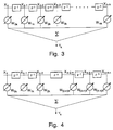
- Fig. 3 shows a linear combiner with an inputsignal x k and with one-clock delays z -1 which deliver respective delayed input signals x k-1 to x k-n .
- Signals x to x k-n are multiplied with respective coefficients w 0k to w nk and summed up to form the corrected output signal y k .
- Fig. 4 is similar to Fig. 3 and shows how the main filter MF can be constructed.
- the coefficients w 0k to w 2k correspond to a first small filter and the coefficients w (2-n)k to w (4-n)k correspond to a second small filter.
- Block z -n is a variable delay with n clocks delay time.
- the positioner 14 seeks for the location, i.e. the position information PI, of the small filters and of the delays within the 1296 taps. This is done according to Fig. 9.
- the last coefficients calculated in filter LMS2 are stored for the case of divergence of the LMS algorithm.
- New coefficients for the small filters are calculated with a second LMS algorithm in filter LMS2 according to Fig. 8 while the locations of the delay parts remain fixed.
- the positioning is re-initiated, whereas in case of convergence the resulting coefficients are loaded from central processor CP to main filter MF.
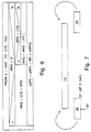
- the long filter LF of Fig. 7 corresponds to filter LMS1 and the short filter SF corresponds to a range for a small filter used in positioner 14.
- the left short filter CF is centred, i.e. the actual position AP corresponds to the central coefficient CeC.
- the coefficients in the right half of CF are identical to the coefficients stored above in LF.
- the coefficients for the left half of CF are taken from the right end of LF (principle of looped delay line).
- the coefficients of the right half of the right filter SF are taken accordingly from the left end of LF.
- Fig. 6 explains how the filter output is received, especially at the beginning and at the end of filter LMS1.
- ARG i.e. the sum of the position within the size LFS of long filter LF and of the index of the actual coefficient
- LFS is added to ARG.
- ARG is greater than LFS
- LFS is subtracted from ARG.
- the actual position AP has index 0 and corresponds to the central coefficient CeC of the small filter.
- the filter output y is calculated by summing up the respective x input values at position ARG which have been multiplied with the coefficient at position ARG.
- the filter coefficients are calculated with the LMS algorithm according to Fig. 8, starting with a preselected filter response. Error ⁇ is calculated and an error statistic and/or the status (e.g. coefficients before, coefficients after, error, frame number, desired filter output) of a test pixel can be recorded in a RAM.
- error statistic and/or the status e.g. coefficients before, coefficients after, error, frame number, desired filter output
- all coefficients are tested if they are greater than a maximum coefficient value or less then a minimum value. If this is true a divergence flag DI is set to '1'. After coefficient calculation it is tested, if the sum S of all coefficients is less then half the central coefficient CeC. If this is true, DI is set to '1', too.
- the adaptation value ⁇ is modified according to Fig.
- the new coefficients for the small filters are calculated with the LMS2 algorithm and tested for divergence. This testing can be done like the testing in case LMS1. However, it may not be necessary to test the sum of the coefficients. In case of divergence the last coefficients stored are used for re-initiation.
- the positioner shifts a window corresponding to a small filter (e.g. 16 taps) along the positions of the delay line.
- a small filter e.g. 16 taps
- the squares of the LMS1 calculated coefficients corresponding to all small filter coefficient positions are summed.
- These 1296 sums are stored together with their position AP in a RAM which is called S/P store. Thereafter the sums in the S/P store are rearranged in decreasing order wherein the corresponding AP of each sum is kept.
- the AP of the highest five sums indicates the positions of the main TV reference signal and the subsequent ghosts. But it has been found that the coefficient areas of the five small filters should not overlap. Therefore the coefficient position ranges of the small filters are compared. If e.g.
- the difference between the first AP and the second AP in the ordered list in the S/P store is smaller than the SFS, i.e. 16, than the both corresponding small filters overlap.
- the second AP and its sum is ignored (e.g. deleted in the S/P store, followed by rearranging of the stored AP's) and the third AP is taken. If the end of the S/P data within the S/P store is reached without having found five correct SF positions, the SF positions already set can be held and the remaining positions (next to set with greatest coeff.).
- the coefficients for the small filters may then be taken from the corresponding neighbouring coefficients of the coefficients C1 from the filter LMS1.
- the positioner can be described as follows:
- ⁇ 1.3 .
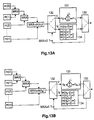
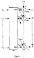
- Fig. 12 to 14 depict the operation of the second embodiment of the positioner.
- a number of k+1 small filters is used.
- Fig. 13B shows the respective steps for getting the last small filter centre position n k .
- the small filter centre positions n 0 , n 1 , ..., n k of (k+1) small filters are resorted in a sorter 141 into ascending order of the positions n j0 , n j1 , ..., n jk for small filters number '0', '1', ..., 'k'.
- the value L/2 (integer) is subtracted in a first subtractor 142, resulting in delay time ⁇ for the first of the variable delays mentioned above.
- E.g. five error classes for error E can be used according to Fig. 10.
- a counter C1 ... C5 is assigned to each error class. If an error according to a specific error class occurs the respective counter is incremented and the counters of the other classes are set to zero. If the counter of the specific error class is greater than a preselected constant CON1 ... CON5, the value for ⁇ is adapted according to Fig. 10 and all counters are set to zero.
- an inventive equalizer with a long time constant and an inventive ghost canceller with a reduced time constant can be connected in series to have a fast response for moving ghosts and to have an exact equalization for static distortions or ghosts.
- the invention can also be used for audio or data transmission having included a (digital) reference signal, e.g. DAB (digital audio broadcasting) and DTB (digital video broadcasting).
- a (digital) reference signal e.g. DAB (digital audio broadcasting) and DTB (digital video broadcasting).
Landscapes
- Engineering & Computer Science (AREA)
- Multimedia (AREA)
- Signal Processing (AREA)
- Filters That Use Time-Delay Elements (AREA)
- Picture Signal Circuits (AREA)
- Cable Transmission Systems, Equalization Of Radio And Reduction Of Echo (AREA)
- Noise Elimination (AREA)
Abstract
Description
- The present invention relates to a method and to an apparatus for ghost cancelling and/or equalizing.
- In "A tutorial on ghost cancelling", W. Ciciora et al, IEEE Transactions on Consumer Electronics, Vol. 25, pages 9 - 44, 25. Feb 1979, the principle of ghost cancelling is described. A received test signal is compared with an ideal version of this test signal. The coefficients of a correction filter applied to the received test signal are adjusted in such a way that the filter output signal matches as much as possible to the ideal test signal. But the filter length is limited and in a lot of cases no sufficient ghost cancellation is possible.
In "Adaptive Noise Cancelling: Principles and Applications", B. Widrow et al, Proceedings of the IEEE, pages 1692 - 1716, Vol. 63, No. 12, Dec. 1975, an LMS (least-mean-square) adaptive filter for noise cancelling is introduced, wherein a new filter coefficient wi(j+1) is calculated according to the formula
- Other examples of prior art are the European patent application EP-A-0 421 526 and the article "A CMOS Subscriber Line Audio Processing Circuit Including Adaptive Balance", author S.J.Poole et al, in Proceedings of the 1988 IEEE International Symposium on Circuits and Systems, Espoo, Finland, June 7-9, 1988.
- It is one object of the invention to disclose a method for ghost cancelling and/or equalizing, where also more complex distortions and ghost signals, respectively, can be handled and where the speed and stability of adaptation is improved. This object is reached by the inventive method disclosed in
claim 1. - It is a further object of the invention to disclose an apparatus which utilizes the inventive method. This object is reached by the inventive apparatus disclosed in claim 5.
- A first long LMS adaptive filter which may have more than 1000 taps minimizes the error ε between the filtered output signal y of the distorted input signal x (a transmitted reference signal) and an ideal reference signal. Normally this ideal reference signal is stored within the ghost canceller/equalizer and corresponds to the reference signal which is transmitted e.g. in a specific TV line. A positioner takes coefficients from the first LMS filter and determines the most useful subset of (say 5) small filters (say 16 taps each) separated by variable delays. The position information calculated in the positioner comprises the lengths of these delays.
The subset of filters forms together with the variable delays a second LMS adaptive filter with a tap number corresponding to the first LMS filter tap number. The coefficients corresponding to the delay 'taps' can be regarded as set to zero and the locations of the delay parts of the second LMS filter remain fixed. The coefficients of the filter parts (corresponding to the small filters) are modified adaptively until the best match between the filtered received reference signal and the ideal reference signal is achieved. This process will recommence if the ghost or the received channel changes.
The first and second LMS filter need not work in real time. After establishing of the filter coefficient modification of the subsets these coefficients are copied to a real time main filter working on the whole input signal (e.g. a TV signal) with exception of said reference signal.
The main filter comprises a respective subset of adjustable small filters and a set of adjustable delays.
In the following a modified equation
- In principle the inventive method consists in ghost cancelling and/or equalizing, wherein the coefficients of a digital filter are in principle continuously adapted to minimize the error between the filter output signal of a distorted reference signal and an ideal reference signal which is stored or which can be decoded correctly after reception,
and wherein said digital filter is a first LMS filter or filter function with a high tap number and the coefficients of this filter or filter function are used by comparing stepwise values derived from such coefficients of said first LMS filter which represent the tap positions of a small filter with a reduced number of coefficients to detect depending on the level of said values the position of one or more variable delays which connect in series two or more of said small filters or filter functions and wherein said connection of small filters and delays forms a second LMS filter, of which the coefficients corresponding to said small filters are adapted and used in a main filter ,
wherein the positions and the delay times of said delays remain fixed during the calculation of the coefficients of said small filters and wherein the signal to be ghost cancelled and/or equalized passes said main filter at those times where said reference signal is not present.
Advantageously the adaptation constant µ for the LMS calculation in said first LMS filter and/or in said second LMS filter is adapted according to a statistic of said errors stored in memory means and updated during each LMS calculation. - Advantageous additional embodiments of the inventive method are resulting from the respective dependent claims.
- In principle the inventive apparatus comprises: a main filter which works on a distorted signal with exception of a reference signal contained within said distorted signal; looped delay means which store said reference signal; a controller circuit which controls said main filter and said delay means; a central processor, which exchanges with said controller circuit control data and which reads from said delay means said reference signal and from a further input said ideal reference signal and which calculates said LMS algorithms and adjusts said variable delays within said main filter and stores said coefficients for said small filters in said main filter.
- Advantageously said central processor exchanges data with a µ-adaptation circuit and adapts the value for said adaptation constant µ according to a statistic of said errors stored and updated in said µ-adaptation circuit.
- Advantageous additional embodiments of the inventive apparatus are resulting from the respective dependent claim.
- Preferred embodiments of the invention will now be described with reference to the accompanying drawings, in which:
- Fig. 1
- shows in principle the function of the inventive apparatus;
- Fig. 2
- shows a block diagram of the inventive apparatus;
- Fig. 3
- depicts an adaptive linear combiner in the form of a single-input transversal filter;
- Fig. 4
- shows a single-input transversal filter in the form of a tapped delay line;
- Fig. 5
- depicts a flow chart diagram of the main algorithm;
- Fig. 6
- shows a flow chart diagram of the output signal calculation;
- Fig. 7
- explains the principle of a closed loop filter for the output signal calculation;
- Fig. 8
- shows a flow chart diagram for the calculation of new coefficients;
- Fig. 9
- shows a flow chart diagram for the positioner;
- Fig. 10
- shows a flow chart diagram for µ-adaptation;
- Fig. 11
- depicts the creation of a ghost signal;
- Fig. 12
- demonstrates the calculation of values m(i);
- Fig. 13
- shows the selection of (k+1) small filter positions;
- Fig. 14
- shows resorting of small filter positions and calculating of delay values.
- In Fig. 11a an original signal of a TV line is depicted. A ghost signal with a delay of t=2 and an amplitude of 50% is shown in Fig. 11b. Fig. 11c shows the combined baseband signal received with a TV set.
- The first adaptive LMS filter LMS1 in Fig. 1 may have 1296 taps and receives a distorted input signal x at
first input 11. By suitable processing a TV line with a reference signal, e.g. line 312 of an even frame and/or line 312 of an odd frame of an HDMAC signal, is extracted from the whole TV signal and fed to input 11. Afirst subtractor 15 calculates the error E1 (ε) between the filtered output signal y of the distorted input signal x (a transmitted reference signal) and an ideal reference signal fed tosecond input 12. Normally this ideal reference signal is stored within a ghost canceller/equalizer and corresponds to the transmitted reference signal. Filter LMS1 calculates its coefficients according to the known LMS algorithm mentioned above. After a certain number of iterations the coefficients are loaded to apositioner 14. This positioner works according to the flow chart of Fig. 9 and determines the most useful subset of e.g. 5 small filters with e.g. 16 taps each, which can be thought as separated by variable delays having a maximum delay time of 1296-5∗16 = 1216 clocks. The position information PI calculated in the positioner comprises the lengths and positions of these delays within a second adaptive LMS filter LMS2 with corresponding 1296 taps. Between each twodelay parts 16 taps of a small filter are located.
The locations of the delay parts remain fixed. Asecond subtractor 16 calculates the error E2 (ε) between the filtered output signal y of the distorted input signal x and the ideal reference signal fed tosecond input 12. The coefficients of the filter parts (corresponding to the small filters) are modified adaptively with the known LMS algorithm until the best match, i.e. a minimum value of E2, between the filtered received reference signal and the ideal reference signal is achieved. Advantageously the first and second LMS filter do not need to work in real time. After establishing of the filter coefficient modification of the subsets these coefficients are copied to a real time main filter working on the whole input signal (e.g. a TV signal) with exception of said reference signal.
The main filter comprises a respective subset of adjustable small filters and a set of adjustable delays. The delays can be regarded as controlled by filter LMS1 and the small filters as controlled by filter LMS2. - In Fig. 2 a hardware block diagram for one possible embodiment of the inventive apparatus is depicted. A digital TV signal which may have been A/D converted is fed via
input 21 to a 1296 tap transversal FIR filter MF, which corresponds to main filter MF in Fig. 1, and to a loopeddelay line 24 which can store 1296 samples of a received reference signal. At theoutput 23 of filter MF the corrected TV signal is available.
The content ofdelay line 24 is loaded (a sample at a time) to a central processor CP which gets also frominput 22 respective samples of an ideal reference signal stored in a ROM or which has been decoded correctly from a received reference signal. CP represents the filters LMS1 and LMS2, thepositioner 14 and the two subtractors 15 and 16 from Fig. 1. In CP the algorithms according to Fig. 5 - 10 are carried out. The central processor also exchanges data with a µ-adaptation circuit µ-A and with acontroller circuit 25.
The µ-adaptation circuit may contain a RAM and e.g. five counters in which E1 and E2, respectively, error values are accumulated and stored.Controller circuit 25 clocks the main filter and thedelay line 24 and selects the special TV line(s) with a reference signal to be stored indelay line 24, while all other TV lines pass through the main filter.
The central processor loads the coefficients of the e.g. five small filters and the lengths of the adjustable delays to the main filter MF.
If the coefficient calculation needs more than one frame period, the valid coefficients can remain fixed for several frame periods. - Fig. 3 shows a linear combiner with an inputsignal xk and with one-clock delays z-1 which deliver respective delayed input signals xk-1 to xk-n. Signals x to xk-n are multiplied with respective coefficients w0k to wnk and summed up to form the corrected output signal yk.
- Fig. 4 is similar to Fig. 3 and shows how the main filter MF can be constructed. The coefficients w0k to w2k correspond to a first small filter and the coefficients w(2-n)k to w(4-n)k correspond to a second small filter. Block z-n is a variable delay with n clocks delay time.
- In Fig. 5 'frame loop' and 'line loop' can be regarded as respective counters located in
controller circuit 25. After switching on the TV set or after choosing another channel the Y-branch of test 'frame = 0' is carried out. Coefficients stored in memory suited to usual or good reception of each received channel could also be used first.
In case of LMS1 calculation new coefficients are calculated according to the flow chart of Fig. 8. In case of divergence of the coefficient modification the coefficient calculation is reinitiated with another preselected filter response. This filter response may be matched to a different reception condition. If the coefficient modification converges and e.g. six modification loops have been made the resulting coefficients are used for thepositioner 14 which works according to Fig. 9.
In case of LMS2 calculation thepositioner 14 seeks for the location, i.e. the position information PI, of the small filters and of the delays within the 1296 taps. This is done according to Fig. 9. The last coefficients calculated in filter LMS2 are stored for the case of divergence of the LMS algorithm. New coefficients for the small filters are calculated with a second LMS algorithm in filter LMS2 according to Fig. 8 while the locations of the delay parts remain fixed. In case of divergence in the coefficient calculation the positioning is re-initiated, whereas in case of convergence the resulting coefficients are loaded from central processor CP to main filter MF. - The long filter LF of Fig. 7 corresponds to filter LMS1 and the short filter SF corresponds to a range for a small filter used in
positioner 14. The left short filter CF is centred, i.e. the actual position AP corresponds to the central coefficient CeC. - The coefficients in the right half of CF are identical to the coefficients stored above in LF. The coefficients for the left half of CF are taken from the right end of LF (principle of looped delay line). The coefficients of the right half of the right filter SF are taken accordingly from the left end of LF.
- Fig. 6 explains how the filter output is received, especially at the beginning and at the end of filter LMS1. If the argument ARG, i.e. the sum of the position within the size LFS of long filter LF and of the index of the actual coefficient, is less than zero, LFS is added to ARG. If ARG is greater than LFS, LFS is subtracted from ARG. The actual position AP has
index 0 and corresponds to the central coefficient CeC of the small filter. The filter output y is calculated by summing up the respective x input values at position ARG which have been multiplied with the coefficient at position ARG. - The filter coefficients are calculated with the LMS algorithm according to Fig. 8, starting with a preselected filter response. Error ε is calculated and an error statistic and/or the status (e.g. coefficients before, coefficients after, error, frame number, desired filter output) of a test pixel can be recorded in a RAM.
In case of LMS1 calculation all coefficients are tested if they are greater than a maximum coefficient value or less then a minimum value. If this is true a divergence flag DI is set to '1'. After coefficient calculation it is tested, if the sum S of all coefficients is less then half the central coefficient CeC. If this is true, DI is set to '1', too.
In case of LMS2 calculation advantageously the adaptation value µ is modified according to Fig. 10. The new coefficients for the small filters are calculated with the LMS2 algorithm and tested for divergence. This testing can be done like the testing in case LMS1. However, it may not be necessary to test the sum of the coefficients. In case of divergence the last coefficients stored are used for re-initiation. - According to Fig. 9 the positioner shifts a window corresponding to a small filter (e.g. 16 taps) along the positions of the delay line. For each actual position AP the squares of the LMS1 calculated coefficients corresponding to all small filter coefficient positions are summed. These 1296 sums are stored together with their position AP in a RAM which is called S/P store. Thereafter the sums in the S/P store are rearranged in decreasing order wherein the corresponding AP of each sum is kept. Normally the AP of the highest five sums indicates the positions of the main TV reference signal and the subsequent ghosts. But it has been found that the coefficient areas of the five small filters should not overlap. Therefore the coefficient position ranges of the small filters are compared. If e.g. the difference between the first AP and the second AP in the ordered list in the S/P store is smaller than the SFS, i.e. 16, than the both corresponding small filters overlap. In this case the second AP and its sum is ignored (e.g. deleted in the S/P store, followed by rearranging of the stored AP's) and the third AP is taken.
If the end of the S/P data within the S/P store is reached without having found five correct SF positions, the SF positions already set can be held and the remaining positions (next to set with greatest coeff.). The coefficients for the small filters may then be taken from the corresponding neighbouring coefficients of the coefficients C1 from the filter LMS1. - The positioner can be described as follows:
- 1. Begin with a large filter of (n+1) coefficients, C(0) to C(n).
- 2. Calculate the squares (or absolute values) of these coefficients, A0 to An.
- 3. For each coefficient position i, form the running sum m(i) of the L coefficients surrounding and including Ai, where L is the small filter length:
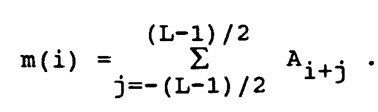
- 4. For each small filter desired:
- 4.1 Find the maximum of m(i). Select a small filter at this position.
- 4.2 Set the L values of m(i) surrounding and including this position to zero.
- The result of this algorithm is to select a set of non-overlapping small filters which try to match the important parts of the large filter as closely as possible. However, under special conditions the positioner may not work correctly. Therefore, in a second embodiment of the
positioner step 3 above can be modified to assign a higher weight to the central coefficient in the sliding window of L coefficients. The formula for m(i) then becomes:
- The value of σ must be chosen as a compromise between making the improvement work and not assigning too much importance to individual coefficients. For example, with small filters of length L = 5 a good value has been found to be σ = 1.3 .
- Fig. 12 to 14 depict the operation of the second embodiment of the positioner. Index i runs from 0 to n and L = 5. A number of k+1 small filters is used.
- Fig. 12A corresponds to
steps
Fig. 12B corresponds to step 3, e.g. m2 = σA2 +(A0 +A1 +A3 +A4). - Fig. 13 corresponds to step 4. From the running sum m(i) the maximum MAX = m(n0) is detected in Fig. 13A. Position n0 is the centre of a first small filter. If this maximum is not zero, the running sums m(i), i = n0-(L-1)/2 to n0+(L-1)/2, are set (134) to zero. If the maximum m(n0) of the sums at position n0 is zero, a
fallback 131 is switched on (132, 133), in which a small filter position n1 adjacent to the last significant filter position is selected by adding L to position n0.
After zero setting of the L running sums the steps of Fig. 13A are repeated for receiving a further maximum. - Fig. 13B shows the respective steps for getting the last small filter centre position nk.
- In Fig. 14 the small filter centre positions n0, n1, ..., nk of (k+1) small filters are resorted in a
sorter 141 into ascending order of the positions nj0, nj1, ..., njk for small filters number '0', '1', ..., 'k'.
From the centre position nj0 for small filter '0' the value L/2 (integer) is subtracted in afirst subtractor 142, resulting in delay time α for the first of the variable delays mentioned above.
From centre position nj1 for small filter '1' the value L and the first centre position nj0 are subtracted in asecond subtractor 143, resulting in delay time β for the second of the variable delays mentioned above.
This procedure is continued respectively. From the last centre position njk for small filter 'k' the value L and the centre position nj(k-1) are subtracted in alast subtractor 144, resulting in delay time λ for the last of the variable delays mentioned above. - E.g. five error classes for error E can be used according to Fig. 10. A counter C1 ... C5 is assigned to each error class. If an error according to a specific error class occurs the respective counter is incremented and the counters of the other classes are set to zero. If the counter of the specific error class is greater than a preselected constant CON1 ... CON5, the value for µ is adapted according to Fig. 10 and all counters are set to zero. The constants may have the following values: CON1 = 2000, CON2 = 1000, CON3 = 500, CON4 = 100, CON5 = 50. Due to the adaptation of µ the inventive method can work with improved speed and stability compared to known methods.
- Programming was done in C language. The figures can be changed accordingly in case of other TV systems or of other reception conditions.
- Advantageously an inventive equalizer with a long time constant and an inventive ghost canceller with a reduced time constant can be connected in series to have a fast response for moving ghosts and to have an exact equalization for static distortions or ghosts.
- The invention can also be used for audio or data transmission having included a (digital) reference signal, e.g. DAB (digital audio broadcasting) and DTB (digital video broadcasting).
-
- AC
- all counters
- AP
- actual position
- ARG
- argument
- C
- counter
- CaC
- calculated coefficient
- CeC
- central coefficient
- CF
- centred filter
- CON
- constant
- DI
- divergence
- E
- error
- E1
-
error 1 - E2
-
error 2 - y
- yes
- LF
- long filter
- LFS
- long filter size
- MC
- main coefficient
- MF
- main filter
- N
- no
- P
- position
- PI
- position information
- RLF
- reduced long filter
- ROC
- rest of counters
- S
- sum
- SF
- short filter
- SFS
- short filter size
- SP
- selected position
- S/P
- sum/position
Claims (6)
- Method for ghost cancelling and/or equalizing, wherein the coefficients (C1) of a digital filter are in principle continuously adapted to minimize the error (ε, E1) between the filter output signal (y) of a distorted reference signal and an ideal reference signal (12, 22) which is stored or which can be decoded correctly after reception, characterized in that said digital filter is a first LMS filter or filter function (LMS1) with a high tap number and that the coefficients (C1) of this filter or filter function are used by comparing stepwise values derived from such coefficients of said first LMS filter which represent the tap positions of a small filter with a reduced number of coefficients to detect depending on the level of said values the position (PI) of one or more variable delays which connect in series two or more of said small filters or filter functionsand that said connection of small filters and delays forms a second LMS filter (LMS2), of which the coefficients (C2) corresponding to said small filters are adapted and used in a main filter (MF),wherein the positions and the delay times of said delays remain fixed during the calculation of the coefficients (C2) of said small filters and wherein the signal to be ghost cancelled and/or equalized passes said main filter (MF) at those times where said reference signal is not present.
- Method according to claim 1, characterized in that the adaptation constant µ for the LMS calculation in said first LMS filter (LMS1) and/or in said second LMS filter (LMS2) is adapted according to a statistic of said errors (E1, E2) stored in memory means and updated during each LMS calculation.
- Method according to claim 1 or 2, characterized in that each of said values is a sum of the squares or absolute values of said corresponding filter coefficients.
- Method according to claim 3, characterized in that before summing up said values to form each of said sums a higher weight is assigned to the central position value involved.
- Apparatus for a method according to any of claims 1 to 4, comprising:a main filter (MF) which works on a distorted signal with exception of a reference signal contained within said distorted signal;looped delay means (24) which store said reference signal;a controller circuit (25) which controls said main filter (MF) and said delay means (24);a central processor (CP), which exchanges with said controller circuit control data and which reads from said delay means (24) said reference signal and from a further input (22) said ideal reference signal and which calculates said LMS algorithms and adjusts said variable delays within said main filter (MF) and stores said coefficients (C2) for said small filters in said main filter (MF).
- Apparatus according to claim 5, characterized in that said central processor (CP) exchanges data with a µ-adaptation circuit (µ-A) and adapts the value for said adaptation constant µ according to a statistic of said errors (E1, E2) stored and updated in said µ-adaptation circuit.
Priority Applications (1)
| Application Number | Priority Date | Filing Date | Title |
|---|---|---|---|
| EP93903937A EP0627136B1 (en) | 1992-02-17 | 1993-02-09 | Method and apparatus for ghost cancelling and/or equalizing |
Applications Claiming Priority (6)
| Application Number | Priority Date | Filing Date | Title |
|---|---|---|---|
| EP92400532 | 1992-02-17 | ||
| EP92400532 | 1992-02-17 | ||
| EP92402679 | 1992-09-29 | ||
| EP92402679 | 1992-09-29 | ||
| EP93903937A EP0627136B1 (en) | 1992-02-17 | 1993-02-09 | Method and apparatus for ghost cancelling and/or equalizing |
| PCT/EP1993/000311 WO1993016527A1 (en) | 1992-02-17 | 1993-02-09 | Method and apparatus for ghost cancelling and/or equalizing |
Publications (2)
| Publication Number | Publication Date |
|---|---|
| EP0627136A1 EP0627136A1 (en) | 1994-12-07 |
| EP0627136B1 true EP0627136B1 (en) | 1996-12-18 |
Family
ID=26132337
Family Applications (1)
| Application Number | Title | Priority Date | Filing Date |
|---|---|---|---|
| EP93903937A Expired - Lifetime EP0627136B1 (en) | 1992-02-17 | 1993-02-09 | Method and apparatus for ghost cancelling and/or equalizing |
Country Status (7)
| Country | Link |
|---|---|
| EP (1) | EP0627136B1 (en) |
| JP (1) | JP3401002B2 (en) |
| DE (1) | DE69306763T2 (en) |
| ES (1) | ES2095633T3 (en) |
| HK (1) | HK58097A (en) |
| SG (1) | SG65590A1 (en) |
| WO (1) | WO1993016527A1 (en) |
Cited By (1)
| Publication number | Priority date | Publication date | Assignee | Title |
|---|---|---|---|---|
| US6289046B1 (en) | 1997-08-04 | 2001-09-11 | Mitsubishi Denki Kabushiki Kaisha | Adaptive equalization method |
Families Citing this family (6)
| Publication number | Priority date | Publication date | Assignee | Title |
|---|---|---|---|---|
| US5610909A (en) * | 1995-05-31 | 1997-03-11 | Lucent Technologies Inc. | Multistage echo canceler including time variation compensation |
| DE19522621B4 (en) * | 1995-06-22 | 2004-01-15 | Atmel Germany Gmbh | Method for decoding transmitted information units |
| RU2244375C1 (en) * | 2003-08-11 | 2005-01-10 | Федеральное Государственное унитарное предприятие Воронежский научно-исследовательский институт связи | Broadband signal search device |
| US20050249274A1 (en) * | 2004-05-10 | 2005-11-10 | Larosa Christopher P | Linear filter equalizer |
| RU2313183C2 (en) * | 2004-11-22 | 2007-12-20 | Федеральное государственное унитарное предприятие "Воронежский научно-исследовательский институт связи" | Device for finding broadband signals |
| CN103227623B (en) * | 2013-03-29 | 2015-09-30 | 北京邮电大学 | The LMS adaptive filter algorithm of variable step size and filter |
Family Cites Families (3)
| Publication number | Priority date | Publication date | Assignee | Title |
|---|---|---|---|---|
| JP2755712B2 (en) * | 1989-08-17 | 1998-05-25 | 株式会社東芝 | Ghost removal apparatus and ghost removal method |
| EP0421526B1 (en) * | 1989-10-06 | 1996-07-31 | Koninklijke Philips Electronics N.V. | Adaptive ghost cancellation circuit |
| IT1240383B (en) * | 1990-07-06 | 1993-12-10 | Seleco Spa | PERFECTED SYSTEM OF COMPENSATION OF REFLECTIONS IN VIDEO SIGNALS |
-
1993
- 1993-02-09 WO PCT/EP1993/000311 patent/WO1993016527A1/en not_active Ceased
- 1993-02-09 EP EP93903937A patent/EP0627136B1/en not_active Expired - Lifetime
- 1993-02-09 SG SG1996008073A patent/SG65590A1/en unknown
- 1993-02-09 ES ES93903937T patent/ES2095633T3/en not_active Expired - Lifetime
- 1993-02-09 JP JP51378193A patent/JP3401002B2/en not_active Expired - Fee Related
- 1993-02-09 DE DE69306763T patent/DE69306763T2/en not_active Expired - Fee Related
-
1997
- 1997-05-01 HK HK58097A patent/HK58097A/en not_active IP Right Cessation
Cited By (1)
| Publication number | Priority date | Publication date | Assignee | Title |
|---|---|---|---|---|
| US6289046B1 (en) | 1997-08-04 | 2001-09-11 | Mitsubishi Denki Kabushiki Kaisha | Adaptive equalization method |
Also Published As
| Publication number | Publication date |
|---|---|
| HK58097A (en) | 1997-05-09 |
| DE69306763D1 (en) | 1997-01-30 |
| JPH07503817A (en) | 1995-04-20 |
| EP0627136A1 (en) | 1994-12-07 |
| SG65590A1 (en) | 1999-06-22 |
| ES2095633T3 (en) | 1997-02-16 |
| DE69306763T2 (en) | 1997-05-07 |
| JP3401002B2 (en) | 2003-04-28 |
| WO1993016527A1 (en) | 1993-08-19 |
Similar Documents
| Publication | Publication Date | Title |
|---|---|---|
| US5539773A (en) | Method and apparatus for ghost cancelling and/or equalizing | |
| US4843583A (en) | Nonlinear adaptive filter | |
| KR0162340B1 (en) | Ghost Elimination Equalizer for Digital Communications Systems | |
| US7120193B2 (en) | Decision feedback equalizer with dynamic feedback control | |
| US4947362A (en) | Digital filter employing parallel processing | |
| US5228058A (en) | Adaptive equalizer | |
| US5512959A (en) | Method for reducing echoes in television equalizer video signals and apparatus therefor | |
| HK58097A (en) | Method and apparatus for ghost cancelling and/or equalizing | |
| CN1113637A (en) | Equalization apparatus with fast coefficient updating operation | |
| US4947252A (en) | Ghost canceling apparatus | |
| JPH0654885B2 (en) | Adaptive equalizer for binary signals and method of operating same | |
| Ahmad et al. | A 2-D recursive inverse adaptive algorithm | |
| US7689637B1 (en) | Adaptive filtering method and related device | |
| WO2001097475A1 (en) | Channel equalizer | |
| US6349112B1 (en) | Adaptive equalizer compensating signal distortion on transmission path | |
| KR100284238B1 (en) | 2-stage accumulator for modulus update | |
| KR100498465B1 (en) | Channel equalizing method and channel equalizer | |
| US20040120394A1 (en) | Decision-feedback equalizer | |
| EP0552577A1 (en) | Ghost signal removal apparatus for broadcasting reception system | |
| EP1344394A2 (en) | Detection and correction of asymmetric transient signals | |
| JPS59139717A (en) | automatic equalizer | |
| KR0176877B1 (en) | Ghost canceling method in image signal processor | |
| KR100245997B1 (en) | Apparatus and method for updating tap coefficients in channel equalizers | |
| Kanemasa et al. | An adaptive filter convergence method for echo cancellation and decision feedback equalization | |
| KR100273343B1 (en) | Channel equalizer |
Legal Events
| Date | Code | Title | Description |
|---|---|---|---|
| PUAI | Public reference made under article 153(3) epc to a published international application that has entered the european phase |
Free format text: ORIGINAL CODE: 0009012 |
|
| 17P | Request for examination filed |
Effective date: 19940806 |
|
| AK | Designated contracting states |
Kind code of ref document: A1 Designated state(s): DE ES FR GB IT |
|
| RAP1 | Party data changed (applicant data changed or rights of an application transferred) |
Owner name: THOMSON MULTIMEDIA |
|
| GRAG | Despatch of communication of intention to grant |
Free format text: ORIGINAL CODE: EPIDOS AGRA |
|
| 17Q | First examination report despatched |
Effective date: 19960227 |
|
| GRAH | Despatch of communication of intention to grant a patent |
Free format text: ORIGINAL CODE: EPIDOS IGRA |
|
| GRAH | Despatch of communication of intention to grant a patent |
Free format text: ORIGINAL CODE: EPIDOS IGRA |
|
| GRAA | (expected) grant |
Free format text: ORIGINAL CODE: 0009210 |
|
| AK | Designated contracting states |
Kind code of ref document: B1 Designated state(s): DE ES FR GB IT |
|
| ITF | It: translation for a ep patent filed | ||
| REF | Corresponds to: |
Ref document number: 69306763 Country of ref document: DE Date of ref document: 19970130 |
|
| REG | Reference to a national code |
Ref country code: ES Ref legal event code: FG2A Ref document number: 2095633 Country of ref document: ES Kind code of ref document: T3 |
|
| ET | Fr: translation filed | ||
| PLBE | No opposition filed within time limit |
Free format text: ORIGINAL CODE: 0009261 |
|
| STAA | Information on the status of an ep patent application or granted ep patent |
Free format text: STATUS: NO OPPOSITION FILED WITHIN TIME LIMIT |
|
| 26N | No opposition filed | ||
| REG | Reference to a national code |
Ref country code: GB Ref legal event code: 746 Effective date: 20010810 |
|
| REG | Reference to a national code |
Ref country code: GB Ref legal event code: IF02 |
|
| REG | Reference to a national code |
Ref country code: FR Ref legal event code: D6 |
|
| PGFP | Annual fee paid to national office [announced via postgrant information from national office to epo] |
Ref country code: ES Payment date: 20080324 Year of fee payment: 16 |
|
| PGFP | Annual fee paid to national office [announced via postgrant information from national office to epo] |
Ref country code: IT Payment date: 20080226 Year of fee payment: 16 Ref country code: GB Payment date: 20080129 Year of fee payment: 16 Ref country code: DE Payment date: 20080221 Year of fee payment: 16 |
|
| PGFP | Annual fee paid to national office [announced via postgrant information from national office to epo] |
Ref country code: FR Payment date: 20080218 Year of fee payment: 16 |
|
| GBPC | Gb: european patent ceased through non-payment of renewal fee |
Effective date: 20090209 |
|
| REG | Reference to a national code |
Ref country code: FR Ref legal event code: ST Effective date: 20091030 |
|
| PG25 | Lapsed in a contracting state [announced via postgrant information from national office to epo] |
Ref country code: DE Free format text: LAPSE BECAUSE OF NON-PAYMENT OF DUE FEES Effective date: 20090901 |
|
| REG | Reference to a national code |
Ref country code: ES Ref legal event code: FD2A Effective date: 20090210 |
|
| PG25 | Lapsed in a contracting state [announced via postgrant information from national office to epo] |
Ref country code: GB Free format text: LAPSE BECAUSE OF NON-PAYMENT OF DUE FEES Effective date: 20090209 Ref country code: FR Free format text: LAPSE BECAUSE OF NON-PAYMENT OF DUE FEES Effective date: 20090302 |
|
| PG25 | Lapsed in a contracting state [announced via postgrant information from national office to epo] |
Ref country code: ES Free format text: LAPSE BECAUSE OF NON-PAYMENT OF DUE FEES Effective date: 20090210 |
|
| PG25 | Lapsed in a contracting state [announced via postgrant information from national office to epo] |
Ref country code: IT Free format text: LAPSE BECAUSE OF NON-PAYMENT OF DUE FEES Effective date: 20090209 |