EP0626732A1 - Battery and intercell connector for it - Google Patents
Battery and intercell connector for it Download PDFInfo
- Publication number
- EP0626732A1 EP0626732A1 EP94303362A EP94303362A EP0626732A1 EP 0626732 A1 EP0626732 A1 EP 0626732A1 EP 94303362 A EP94303362 A EP 94303362A EP 94303362 A EP94303362 A EP 94303362A EP 0626732 A1 EP0626732 A1 EP 0626732A1
- Authority
- EP
- European Patent Office
- Prior art keywords
- positive
- casing
- buss bars
- connector
- electrode
- Prior art date
- Legal status (The legal status is an assumption and is not a legal conclusion. Google has not performed a legal analysis and makes no representation as to the accuracy of the status listed.)
- Withdrawn
Links
Images


Classifications
-
- H—ELECTRICITY
- H01—ELECTRIC ELEMENTS
- H01M—PROCESSES OR MEANS, e.g. BATTERIES, FOR THE DIRECT CONVERSION OF CHEMICAL ENERGY INTO ELECTRICAL ENERGY
- H01M10/00—Secondary cells; Manufacture thereof
- H01M10/34—Gastight accumulators
- H01M10/345—Gastight metal hydride accumulators
-
- H—ELECTRICITY
- H01—ELECTRIC ELEMENTS
- H01M—PROCESSES OR MEANS, e.g. BATTERIES, FOR THE DIRECT CONVERSION OF CHEMICAL ENERGY INTO ELECTRICAL ENERGY
- H01M50/00—Constructional details or processes of manufacture of the non-active parts of electrochemical cells other than fuel cells, e.g. hybrid cells
- H01M50/50—Current conducting connections for cells or batteries
- H01M50/531—Electrode connections inside a battery casing
- H01M50/54—Connection of several leads or tabs of plate-like electrode stacks, e.g. electrode pole straps or bridges
-
- Y—GENERAL TAGGING OF NEW TECHNOLOGICAL DEVELOPMENTS; GENERAL TAGGING OF CROSS-SECTIONAL TECHNOLOGIES SPANNING OVER SEVERAL SECTIONS OF THE IPC; TECHNICAL SUBJECTS COVERED BY FORMER USPC CROSS-REFERENCE ART COLLECTIONS [XRACs] AND DIGESTS
- Y02—TECHNOLOGIES OR APPLICATIONS FOR MITIGATION OR ADAPTATION AGAINST CLIMATE CHANGE
- Y02E—REDUCTION OF GREENHOUSE GAS [GHG] EMISSIONS, RELATED TO ENERGY GENERATION, TRANSMISSION OR DISTRIBUTION
- Y02E60/00—Enabling technologies; Technologies with a potential or indirect contribution to GHG emissions mitigation
- Y02E60/10—Energy storage using batteries
Definitions
- the present invention relates to an intercell connector which is used in the construction of a CPV (common pressure vessel) battery. More particularly, the invention relates to a connector which respectively electrically inter-connects the positive and negative electrodes of a particular cell to external positive and negative terminals so that adjacent cells can be electrically inter-connected.
- CPV common pressure vessel
- Ni-H2 batteries for satellite application employed individual pressure vessels for each cell in the battery.
- This type of Ni-H2 battery is termed in the art a common pressure vessel (CPV) battery.
- CPV common pressure vessel
- Examples of common pressure vessel type Ni-H2 batteries are described in the following publications: M. Earl et al., "Design and Development of an Aerospace CPV Ni/H2 Battery", 24th Intersociety Energy Conversion Engineering Conference, Washington, D.C., August 1989, Proc ., Vol. 3, pp. 1395-1400; J.
- each battery cell includes a plurality of positive and negative electrodes which are encased in a plastic casing or the like. Within each cell, the positive and negative electrodes are respectively interconnected to one another utilizing positive and negative buss bars. In order to electrically connect adjacent cells, it is necessary that the positive and negative buss bars be respectively connected to positive and negative terminals disposed externally of the casing. In this manner, adjacent cells can be interconnected to one another as necessary to satisfy specific voltage requirements.
- an intercell connector for electrically inter-connecting a plurality of battery cells, each of said battery cells including a plurality of spaced apart positive and negative electrode plates encased in a plastic casing, comprises: first and second buss bars disposed in spaced apart relation to each other and each including a base portion and an electrode connecting portion extending from said base portion, said base portions of said first and second buss bars respectively including first and second electrode terminals aligned in a longitudinal direction; and insulating means for insulating said first and second buss bars from each other, wherein said connector is disposed in said casing of each of said cells so as to extend transversely to said electrode plates with said casing being bonded to a portion of said insulating means such that only said electrode terminals are exposed outside said casing to allow inter-connection of said connector with adjacent connectors, and wherein said electrode connecting portions of said first and second buss bars are respectively electrically connected to said positive and negative electrodes.
- a battery comprises: a pressure vessel; at least one rack disposed within said pressure vessel and including a plurality of fins dividing said rack into a plurality of compartments; and a plurality of battery cells, at least one of said battery cells being disposed in each of said compartments, said cells each including a plurality of spaced apart positive and negative electrode plates, a plastic casing in which said electrode plates are sealed and an intercell connector bonded to said plastic casing, said connector including positive and negative electrode terminals disposed externally of said plastic casing and connecting means for respectively electrically connecting said positive and negative electrode plates to said positive and negative electrode terminals, wherein said positive and negative electrode terminals are respectively connectable to negative and positive electrode terminals of adjacent cells.
- the invention provides an intercell connector for use in a common pressure vessel type Ni-H2 battery which experiences minimal leakage of the liquid electrolyte from the casing of the cells thus extending the life of the battery.
- the intercell connector preferably further includes a spacer disposed between the buss bars for maintaining a space therebetween.
- the insulator is preferably made of a plastic which adheres well to metal and encapsulates the buss bars excluding the electrode connecting portions and the electrode terminals.
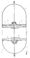
- Fig. 1 illustrates the general arrangement of the Ni-H2 battery 2 including a pressure vessel 4 comprised of a central cylindrical portion 6 capped at respective ends by semi-spherical end portions 8 and 10. Two identical cell stacks 12 are mounted adjacent one another within the pressure vessel 4.
- Each of the cell stacks 12 includes a cell rack 14 which has a generally semi-cylindrical outer configuration.
- the interior of the cell rack 14 is divided by walls or fins 16 into cell-receiving compartments in which are disposed the individual battery cells 18.
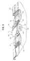
- Fig. 2 is a top view illustrating two adjacent cells 18 separated by the fin 16 and Fig. 3 is a perspective view illustrating a single cell.
- Each cell 18 contains a repeating pattern of a gas diffusion screen (not shown), negative electrode plate 20, separator (not shown) and positive electrode plate 22. The arrangement and selection of the materials for these components is conventional and well within the skill of those familiar with the art.
- Each cell 18 is encased in a plastic casing 24 which electrically insulates the above mentioned components from the fins 16 and in which is provided an electrolyte solution. Also provided in the plastic casing 24 is an intercell connector 26 for respectively interconnecting the negative and positive electrode plates 20 and 22 to positive terminal 28 and a negative terminal 30.
- the intercell connector 26 is also shown in Figures 3 and 4.
- the connector 26 includes a pair of buss bars 32, 34 which are spaced apart from one another by means of a tubular spacer 36 and insulated from one another by an insulator 38.
- Each of the buss bars include a disk-shaped base portion 40 having a hole 39 therein and an electrode connecting portion 42 extending tangentially from the base portion.
- the insulator 38 consists of molded plastic which substantially encapsulates the spacer 36 and the base portion 40 of each of the buss bars.
- each of the buss bars protrude outwardly from the insulator as illustrated in Figure 3 so that they can be respectively connected to the negative and positive electrode plates 20, 22 by welding respective tabs 41 of the electrodes to the electrode connecting portions 42, as illustrated in Figs. 2 and 3.
- other known techniques may be used to fasten the tabs 41 to the electrode connecting portions 42.
- buss bars 32, 34 are similarly configured with the exception that one of the buss bars 34 includes a recessed portion 44 corresponding to a female electrode terminal while the other buss bar 32 includes a protruding portion 46 corresponding to a male electrode terminal.
- the male and female electrode terminals respectively correspond to the above positive and negative terminals 28 and 30.
- the male terminal may be positive or negative with the female terminal being of the opposite polarity.
- adjacent cells can be interconnected to one another by engaging the male terminal of one connector into the female terminal of the other connector, as discussed in greater detail below. Both the protruding portion 46 of the male terminal and the recessed portion 44 of the female terminal are exposed, that is, they are not covered by the insulator 38.
- the plastic casing 24 which encapsulates the electrodes includes opposing openings 48 as illustrated in Figure 4.
- the connector 26 is positioned within the casing with the female or negative electrode terminal 30 aligned with one of the holes and the male or positive terminal 28 aligned with the opposite hole.
- the portions of the plastic casing 24 around the perimeter of the openings 48 are heat sealed to the plastic insulator 38 as identified by reference numeral 50 in Fig. 5 in such a manner that the male and female terminals 28 and 30 are expose to the exterior of the casing, as best illustrated in Figure 5. Since the plastic casing is being bonded to the plastic insulator 38, superior sealing performance can be achieved thereby preventing leakage of the liquid electrolyte from the casing and attendantly extending the life of the battery.
- Figure 2 illustrates the manner in which the connectors can be interconnected to one another by engaging the male terminal 28 of one intercell connector with the female terminal 30 of the adjacent intercell connector.
- a rod 52 is passed through the axial hole 39 in each of the connectors with one end of the rod including a head (not shown) and the other end of the rod being threaded (not shown) for receiving a nut so as to urge the cells together.
- any other known technique may be used to interconnect the cells.
- the interconnector 26 is formed utilizing an injection molding process.
- the spacer 36 and the buss bars 32, 34 are fixedly secured in the die in the proper orientation and a polymer is injected into the cavity defined by the dies. It is important that the polymer be of a type which positively adheres to the metal buss bars.
- One known type of such a metal adhering copolymer is PRIMACOR® made by Dow Chemical.
- the PRIMACOR® polymer is obtained by the co-polymerization of ethylene and acrylic acid, and is a polymer with carboxyl groups randomly distributed along the molecular chain.
- the carboxyl groups disrupt crystallinity, cause the polymer to be more amorphous than LDPE and lowers its melting point, thus providing excellent low temperature sealability.
- the carboxyl groups also provide sites for the intermolecular hydrogen bonding, as well as exceptional adhesion to polar substrates.
- NUCREL Trade Mark
- a second type of polymer material is an ionomer including SURLYN (Trade Mark) made by DuPont.
- SURLYN Trade Mark
- SURLYN Trade Mark
- ethylene and methacrylic acid co-polymers with metallic salts resulting in a tough, transparent and chemically and temperature resistant material which adheres well to metals.
- the electrolyte solution provided in the plastic casing is substantially prevented from leaking through the opening in the casing due to the bonding of the casing to the plastic insulator. Therefore, the life of the battery is maximized.
- the invention can be applied to batteries having individual pressure vessels. Further, the invention can be applied to batteries other than those of the Ni-H2 type.
Landscapes
- Chemical & Material Sciences (AREA)
- Chemical Kinetics & Catalysis (AREA)
- Electrochemistry (AREA)
- General Chemical & Material Sciences (AREA)
- Engineering & Computer Science (AREA)
- Manufacturing & Machinery (AREA)
- Connection Of Batteries Or Terminals (AREA)
- Sealing Battery Cases Or Jackets (AREA)
Abstract
An intercell connector (26) electrically inter-connects a plurality of battery cells (18), each including a plurality of spaced apart positive and negative electrode plates (20, 22) encased in a plastic casing (24). The intercell connector (26) includes first and second buss bars (32, 34) disposed in spaced apart relation to each other and each including a base portion (40) and an electrode connecting portion (42) extending from the base portion (40). The base portions (40) of the first and second buss bars (32, 34) respectively includes first and second electrode terminals (44, 46) aligned with each other; and an insulator (38) for insulating the first and second buss bars (32, 34) from each other. The connector (26) is disposed in the casing (24) of each of the cells (18) so as to extend trans-versely to the electrode plates (20, 22) with the casing (24) being bonded to a portion of the insulator (38) such that only the electrode terminals (44, 46) are exposed outside the casing (24). The first electrode terminal (44) includes a female connecting portion and the second electrode terminal (46) includes a male connecting portion to facilitate inter-connection of adjacent cells (18). Additionally, the electrode connecting portions (42) of the first and second buss bars (32, 34) are respectively electrically connected to the positive and negative electrode plates (20, 22). The intercell connector (26) further includes a spacer (36) disposed between the buss bars (32, 34) for maintaining a space between the buss bars (32, 34).
Description
- The present invention relates to an intercell connector which is used in the construction of a CPV (common pressure vessel) battery. More particularly, the invention relates to a connector which respectively electrically inter-connects the positive and negative electrodes of a particular cell to external positive and negative terminals so that adjacent cells can be electrically inter-connected.
- The earliest Ni-H₂ batteries for satellite application employed individual pressure vessels for each cell in the battery. However, to gain improvements in specific energy and energy density and to reduce the total weight and volume of the battery, the recent trend has been to incorporate multiple cells in a stack arrangement within a single pressure vessel. This type of Ni-H₂ battery is termed in the art a common pressure vessel (CPV) battery. Examples of common pressure vessel type Ni-H₂ batteries are described in the following publications: M. Earl et al., "Design and Development of an Aerospace CPV Ni/H₂ Battery", 24th Intersociety Energy Conversion Engineering Conference, Washington, D.C., August 1989, Proc., Vol. 3, pp. 1395-1400; J. Dunlop et al., "Making Space Nickel/Hydrogen Batteries Light and Less Expensive", AIAA/DARPA Meeting on Lightweight Satellite Systems, Monterey, California, August 1987, NTIS No. N88-13530; G. Holleck, "Common Pressure Vessel Nickel-Hydrogen Battery Design", 15th Intersociety Energy Conversion Engineering Conference, Seattle, Washington, August 1980, Proc., Vol. 3, pp. 1908-1911; and E. Adler et al. "Design Considerations Related to Nickel Hydrogen Common Pressure Vessel Battery Modules", 21st Intersociety Energy conversion Engineering Conference, San Diego, California, August 1986, Proc., Vol. 3, pp. 1554-1559.
- In CPV batteries, the individual cells are generally disposed inside an insulating carrier. Each battery cell includes a plurality of positive and negative electrodes which are encased in a plastic casing or the like. Within each cell, the positive and negative electrodes are respectively interconnected to one another utilizing positive and negative buss bars. In order to electrically connect adjacent cells, it is necessary that the positive and negative buss bars be respectively connected to positive and negative terminals disposed externally of the casing. In this manner, adjacent cells can be interconnected to one another as necessary to satisfy specific voltage requirements.
- In order to connect the internally disposed buss bars to the external terminals, it is necessary to provide openings in the casing. With the conventional cell design, it has been difficult to adequately seal the casing in the area circumscribing the openings to prevent leakage of the electrolyte liquid disposed in the casing. One known sealing technique involves providing a seal between each of the buss bars and the casing and a belleville washer externally of the casing for compressing the casing against the buss bars with the seal interposed therebetween. However, such a technique has not been successful in adequately preventing leakage so that the life of the battery is shortened.
- According to a first aspect of this invention, an intercell connector for electrically inter-connecting a plurality of battery cells, each of said battery cells including a plurality of spaced apart positive and negative electrode plates encased in a plastic casing, comprises:
first and second buss bars disposed in spaced apart relation to each other and each including a base portion and an electrode connecting portion extending from said base portion, said base portions of said first and second buss bars respectively including first and second electrode terminals aligned in a longitudinal direction; and
insulating means for insulating said first and second buss bars from each other,
wherein said connector is disposed in said casing of each of said cells so as to extend transversely to said electrode plates with said casing being bonded to a portion of said insulating means such that only said electrode terminals are exposed outside said casing to allow inter-connection of said connector with adjacent connectors, and
wherein said electrode connecting portions of said first and second buss bars are respectively electrically connected to said positive and negative electrodes. - According to a second aspect of this invention, a battery comprises:
a pressure vessel;
at least one rack disposed within said pressure vessel and including a plurality of fins dividing said rack into a plurality of compartments; and
a plurality of battery cells, at least one of said battery cells being disposed in each of said compartments, said cells each including a plurality of spaced apart positive and negative electrode plates, a plastic casing in which said electrode plates are sealed and an intercell connector bonded to said plastic casing, said connector including positive and negative electrode terminals disposed externally of said plastic casing and connecting means for respectively electrically connecting said positive and negative electrode plates to said positive and negative electrode terminals,
wherein said positive and negative electrode terminals are respectively connectable to negative and positive electrode terminals of adjacent cells. - The invention provides an intercell connector for use in a common pressure vessel type Ni-H₂ battery which experiences minimal leakage of the liquid electrolyte from the casing of the cells thus extending the life of the battery.
- Additionally, the electrode connecting portions of the first and second buss bars are respectively electrically connected to the positive and negative electrode plates. The intercell connector preferably further includes a spacer disposed between the buss bars for maintaining a space therebetween. The insulator is preferably made of a plastic which adheres well to metal and encapsulates the buss bars excluding the electrode connecting portions and the electrode terminals.
- Preferred embodiments of the invention will now be described with reference to the accompanying drawings, in which:-
- Fig. 1 is a partially cut-away cross-sectional view of a common pressure vessel type Ni-H₂ battery according to the present invention;
- Fig. 2 is an exploded view illustrating a pair of cells of the battery in Fig. 1 including the intercell connector according to the present invention;
- Fig. 3 is a perspective view of a cell including the intercell connector; and
- Figs. 4 and 5 are perspective views of the intercell connector according to the present invention illustrating the manner in which the connector is bonded to the plastic casing of the cell.
- Fig. 1 illustrates the general arrangement of the Ni-
H₂ battery 2 including a pressure vessel 4 comprised of a centralcylindrical portion 6 capped at respective ends bysemi-spherical end portions identical cell stacks 12 are mounted adjacent one another within the pressure vessel 4. - Each of the
cell stacks 12 includes acell rack 14 which has a generally semi-cylindrical outer configuration. The interior of thecell rack 14 is divided by walls orfins 16 into cell-receiving compartments in which are disposed theindividual battery cells 18. - Fig. 2 is a top view illustrating two
adjacent cells 18 separated by thefin 16 and Fig. 3 is a perspective view illustrating a single cell. Eachcell 18 contains a repeating pattern of a gas diffusion screen (not shown),negative electrode plate 20, separator (not shown) andpositive electrode plate 22. The arrangement and selection of the materials for these components is conventional and well within the skill of those familiar with the art. Eachcell 18 is encased in aplastic casing 24 which electrically insulates the above mentioned components from thefins 16 and in which is provided an electrolyte solution. Also provided in theplastic casing 24 is anintercell connector 26 for respectively interconnecting the negative andpositive electrode plates positive terminal 28 and anegative terminal 30. - The
intercell connector 26 is also shown in Figures 3 and 4. Theconnector 26 includes a pair ofbuss bars tubular spacer 36 and insulated from one another by aninsulator 38. Each of the buss bars include a disk-shaped base portion 40 having ahole 39 therein and anelectrode connecting portion 42 extending tangentially from the base portion. Theinsulator 38 consists of molded plastic which substantially encapsulates thespacer 36 and thebase portion 40 of each of the buss bars. Theelectrode connecting portions 42 of each of the buss bars protrude outwardly from the insulator as illustrated in Figure 3 so that they can be respectively connected to the negative andpositive electrode plates respective tabs 41 of the electrodes to theelectrode connecting portions 42, as illustrated in Figs. 2 and 3. Of course, other known techniques may be used to fasten thetabs 41 to theelectrode connecting portions 42. - Each of the
buss bars buss bars 34 includes arecessed portion 44 corresponding to a female electrode terminal while theother buss bar 32 includes aprotruding portion 46 corresponding to a male electrode terminal. The male and female electrode terminals respectively correspond to the above positive andnegative terminals protruding portion 46 of the male terminal and therecessed portion 44 of the female terminal are exposed, that is, they are not covered by theinsulator 38. - As explained above, the
plastic casing 24 which encapsulates the electrodes includesopposing openings 48 as illustrated in Figure 4. Theconnector 26 is positioned within the casing with the female ornegative electrode terminal 30 aligned with one of the holes and the male orpositive terminal 28 aligned with the opposite hole. In order to prevent the liquid electrolyte from leaking from the casing, the portions of theplastic casing 24 around the perimeter of theopenings 48 are heat sealed to theplastic insulator 38 as identified byreference numeral 50 in Fig. 5 in such a manner that the male andfemale terminals plastic insulator 38, superior sealing performance can be achieved thereby preventing leakage of the liquid electrolyte from the casing and attendantly extending the life of the battery. - Figure 2 illustrates the manner in which the connectors can be interconnected to one another by engaging the
male terminal 28 of one intercell connector with thefemale terminal 30 of the adjacent intercell connector. In order to retain the cells together, arod 52 is passed through theaxial hole 39 in each of the connectors with one end of the rod including a head (not shown) and the other end of the rod being threaded (not shown) for receiving a nut so as to urge the cells together. Of course, it is understood that any other known technique may be used to interconnect the cells. - The following is a description of the manner in which the connector is manufactured. The
interconnector 26 is formed utilizing an injection molding process. In particular, thespacer 36 and thebuss bars - A second type of polymer material is an ionomer including SURLYN (Trade Mark) made by DuPont. SURLYN (Trade Mark) is obtained by partially reacting ethylene and methacrylic acid co-polymers with metallic salts, resulting in a tough, transparent and chemically and temperature resistant material which adheres well to metals.
- With the above described intercell connector, the electrolyte solution provided in the plastic casing is substantially prevented from leaking through the opening in the casing due to the bonding of the casing to the plastic insulator. Therefore, the life of the battery is maximized.
- Although it is preferred to practice the invention with a common pressure vessel type battery, the invention can be applied to batteries having individual pressure vessels. Further, the invention can be applied to batteries other than those of the Ni-H₂ type.
Claims (8)
- An intercell connector (26) for electrically inter-connecting a plurality of battery cells, each of said battery cells including a plurality of spaced apart positive and negative electrode plates (20, 22) encased in a plastic casing (24), said connector comprising:
first and second buss bars (32, 34) disposed in spaced apart relation to each other and each including a base portion (40) and an electrode connecting portion (42) extending from said base portion (40), said base portions (40) of said first and second buss bars respectively including first and second electrode terminals (44, 46) aligned in a longitudinal direction; and
insulating means (38) for insulating said first and second buss bars (32, 34) from each other,
wherein said connector (26) is disposed in said casing (24) of each of said cells so as to extend transversely to said electrode plates (20, 22) with said casing (24) being bonded to a portion of said insulating means (38) such that only said electrode terminals (44, 46) are exposed outside said casing to allow inter-connection of said connector (26) with adjacent connectors and
wherein said electrode connecting portions (42) of said first and second buss bars (32, 34) are respectively electrically connected to said positive and negative electrodes (20, 22). - A battery (2), comprising:
a pressure vessel (8);
at least one rack (14) disposed within said pressure vessel (8) and including a plurality of fins (16) dividing said rack (14) into a plurality of compartments; and
a plurality of battery cells (18), at least one of said battery cells (18) being disposed in each of said compartments, said cells (18) each including a plurality of spaced apart positive and negative electrode plates (20, 22), a plastic casing (24) in which said electrode plates (20, 22) are sealed and an intercell connector (26) bonded to said plastic casing (24), said connector (26) including positive and negative electrode terminals (44, 46) disposed externally of said plastic casing (24) and connecting means (32, 34) for respectively electri-cally connecting said positive and negative electrode plates (20, 22) to said positive and negative electrode terminals (44, 46), wherein said positive and negative electrode terminals (44, 46) are respectively connectable to negative and positive electrode terminals (44, 46) of adjacent cells. - A battery according to claim 2, wherein said connecting means comprises first and second buss bars (32, 34) disposed in spaced apart relation to each other and each including a base portion (40) and an electrode connecting portion (42) extending from said base portion (40), wherein said connecting portion (42) of said first buss bar (32) is connected to said positive electrode plates (20) and said connecting portion (42) of said second buss bar (34) is connected to said negative electrode plates (22) and wherein said base portions (40) of said first and second buss bars (32, 34) respectively include said positive and negative electrode terminals (44, 46); and
insulating means (38) for insulating said first and second buss bars (32, 34) from each other. - A battery according to claim 3, wherein said connector (26) is disposed in said casing (24) of each of said cells so as to extend transversely to said electrode plates (20, 22) with said casing (24) being bonded to a portion of said insulating means (38) such that only said electrode terminals (44, 46) are exposed outside said casing (24) to allow inter-connection of said connector (26) with adjacent connectors (26).
- The intercell connector battery according to any one of the preceding claims, further comprising a spacer (36) disposed between said buss bars (32, 34) for maintaining a space between said buss bars (32, 34).
- An intercell connector or battery according to any one of the preceding claims, wherein said insulating means (38) encapsulates said buss bars (32, 34) excluding said electrode connecting portions (42) and said electrode terminals (44, 46).
- An intercell connector or battery according to any one of the preceding claims, wherein said insulating means (38) includes a plastic which adheres to metal.
- An intercell connector or battery according to any one of the preceding claims, wherein said first electrode terminal (44) includes a female connecting portion and said second electrode terminal (46) includes a male connecting portion.
Applications Claiming Priority (2)
| Application Number | Priority Date | Filing Date | Title |
|---|---|---|---|
| US66207 | 1993-05-25 | ||
| US08/066,207 US5310609A (en) | 1993-05-25 | 1993-05-25 | Battery cell terminal seal/intercell connector |
Publications (1)
| Publication Number | Publication Date |
|---|---|
| EP0626732A1 true EP0626732A1 (en) | 1994-11-30 |
Family
ID=22067967
Family Applications (1)
| Application Number | Title | Priority Date | Filing Date |
|---|---|---|---|
| EP94303362A Withdrawn EP0626732A1 (en) | 1993-05-25 | 1994-05-10 | Battery and intercell connector for it |
Country Status (3)
| Country | Link |
|---|---|
| US (1) | US5310609A (en) |
| EP (1) | EP0626732A1 (en) |
| JP (1) | JPH0714567A (en) |
Cited By (1)
| Publication number | Priority date | Publication date | Assignee | Title |
|---|---|---|---|---|
| GB2640696A (en) * | 2024-05-02 | 2025-11-05 | Jaguar Land Rover Ltd | Battery cell |
Families Citing this family (3)
| Publication number | Priority date | Publication date | Assignee | Title |
|---|---|---|---|---|
| US9028986B2 (en) * | 2009-01-07 | 2015-05-12 | A123 Systems Llc | Fuse for battery cells |
| US8257848B2 (en) * | 2009-01-12 | 2012-09-04 | A123 Systems, Inc. | Safety venting mechanism with tearing tooth structure for batteries |
| EP2507891B1 (en) | 2009-12-04 | 2018-03-28 | A123 Systems LLC | Battery with integrated power management system and scalable battery cutoff component |
Citations (2)
| Publication number | Priority date | Publication date | Assignee | Title |
|---|---|---|---|---|
| EP0449511A2 (en) * | 1990-03-30 | 1991-10-02 | Communications Satellite Corporation | Battery |
| EP0478038A1 (en) * | 1990-09-12 | 1992-04-01 | General Motors Corporation | Bipolar battery and assembly method |
Family Cites Families (7)
| Publication number | Priority date | Publication date | Assignee | Title |
|---|---|---|---|---|
| US4115630A (en) * | 1977-03-17 | 1978-09-19 | Communications Satellite Corporation | Metal-hydrogen battery |
| US4689544A (en) * | 1985-10-17 | 1987-08-25 | Hughes Aircraft Company | Control of the charging of pressurized gas-metal electrical storage cells |
| US4923769A (en) * | 1989-04-07 | 1990-05-08 | Globe-Union Inc. | Pressure vessel construction for a metal oxide-hydrogen battery |
| US4957830A (en) * | 1989-04-07 | 1990-09-18 | Globe-Union Inc. | Rechargeable metal oxide-hydrogen battery |
| US5082754A (en) * | 1990-05-24 | 1992-01-21 | Globe-Union Inc. | Pressure vessel construction for a metal oxide-hydrogen battery |
| US5135824A (en) * | 1990-09-28 | 1992-08-04 | Globe-Union Inc. | Coaxial terminal construction for a sealed pressurized battery |
| US5090612A (en) * | 1991-02-13 | 1992-02-25 | Globe-Union Inc. | Method of fabricating a pressure vessel for a metal oxide-hydrogen battery |
-
1993
- 1993-05-25 US US08/066,207 patent/US5310609A/en not_active Expired - Fee Related
-
1994
- 1994-05-10 EP EP94303362A patent/EP0626732A1/en not_active Withdrawn
- 1994-05-25 JP JP6133886A patent/JPH0714567A/en active Pending
Patent Citations (2)
| Publication number | Priority date | Publication date | Assignee | Title |
|---|---|---|---|---|
| EP0449511A2 (en) * | 1990-03-30 | 1991-10-02 | Communications Satellite Corporation | Battery |
| EP0478038A1 (en) * | 1990-09-12 | 1992-04-01 | General Motors Corporation | Bipolar battery and assembly method |
Cited By (2)
| Publication number | Priority date | Publication date | Assignee | Title |
|---|---|---|---|---|
| GB2640696A (en) * | 2024-05-02 | 2025-11-05 | Jaguar Land Rover Ltd | Battery cell |
| WO2025228842A1 (en) * | 2024-05-02 | 2025-11-06 | Jaguar Land Rover Limited | Battery cell |
Also Published As
| Publication number | Publication date |
|---|---|
| US5310609A (en) | 1994-05-10 |
| JPH0714567A (en) | 1995-01-17 |
Similar Documents
| Publication | Publication Date | Title |
|---|---|---|
| US11764432B2 (en) | Aggregated battery system | |
| CA2297738C (en) | Solid-state energy storage module employing integrated interconnect board | |
| KR102378374B1 (en) | Battery Module Having Bus-bar and Battery Pack | |
| US5470679A (en) | Method of assembling a bipolar lead-acid battery and the resulting bipolar battery | |
| US12537246B2 (en) | Pouch film stack and secondary battery | |
| US5682671A (en) | Method of assembling a bipolar battery and bipolar battery | |
| US20080090146A1 (en) | Bipolar Battery Electrode Structure and Sealed Bipolar Battery Assembly | |
| US5374490A (en) | Rechargeable battery | |
| US11139517B2 (en) | Battery pack comprising electrode terminal connection plate | |
| EP0449511B1 (en) | Battery | |
| US7879491B2 (en) | Electrode assembly having member for holding electrodes and secondary battery comprising the same | |
| JP7475536B2 (en) | Battery cell, battery, power utilization device, and device and method for manufacturing battery cell | |
| US20190067671A1 (en) | Lead Tab for Battery Terminal | |
| KR20100033831A (en) | Battery cell and battery pack having the same | |
| US10720629B2 (en) | Bipolar battery | |
| EP4224621B1 (en) | Secondary battery and device including same | |
| US20230299437A1 (en) | All solid secondary battery and module of the same | |
| US5310609A (en) | Battery cell terminal seal/intercell connector | |
| CN118899630A (en) | Battery, battery preparation method, battery pack and power-using device | |
| KR20180086697A (en) | Connector and battery module including the same | |
| US20260031449A1 (en) | Cap assembly and secondary battery including same | |
| US20260128427A1 (en) | Pouch Film Stack and Secondary Battery | |
| EP4571950A1 (en) | Secondary battery | |
| WO2026020392A1 (en) | Battery cell, battery and electric device | |
| CN121439869A (en) | Square aluminum-cased battery and its assembly method |
Legal Events
| Date | Code | Title | Description |
|---|---|---|---|
| PUAI | Public reference made under article 153(3) epc to a published international application that has entered the european phase |
Free format text: ORIGINAL CODE: 0009012 |
|
| AK | Designated contracting states |
Kind code of ref document: A1 Designated state(s): DE FR GB IT |
|
| 17P | Request for examination filed |
Effective date: 19950426 |
|
| 17Q | First examination report despatched |
Effective date: 19950907 |
|
| GRAH | Despatch of communication of intention to grant a patent |
Free format text: ORIGINAL CODE: EPIDOS IGRA |
|
| STAA | Information on the status of an ep patent application or granted ep patent |
Free format text: STATUS: THE APPLICATION IS DEEMED TO BE WITHDRAWN |
|
| 18D | Application deemed to be withdrawn |
Effective date: 19960425 |