EP0626677B1 - Magnetic recording medium - Google Patents
Magnetic recording medium Download PDFInfo
- Publication number
- EP0626677B1 EP0626677B1 EP94107618A EP94107618A EP0626677B1 EP 0626677 B1 EP0626677 B1 EP 0626677B1 EP 94107618 A EP94107618 A EP 94107618A EP 94107618 A EP94107618 A EP 94107618A EP 0626677 B1 EP0626677 B1 EP 0626677B1
- Authority
- EP
- European Patent Office
- Prior art keywords
- particle
- density
- protective film
- carbon protective
- range
- Prior art date
- Legal status (The legal status is an assumption and is not a legal conclusion. Google has not performed a legal analysis and makes no representation as to the accuracy of the status listed.)
- Expired - Lifetime
Links
Images




Classifications
-
- G—PHYSICS
- G11—INFORMATION STORAGE
- G11B—INFORMATION STORAGE BASED ON RELATIVE MOVEMENT BETWEEN RECORD CARRIER AND TRANSDUCER
- G11B5/00—Recording by magnetisation or demagnetisation of a record carrier; Reproducing by magnetic means; Record carriers therefor
- G11B5/84—Processes or apparatus specially adapted for manufacturing record carriers
- G11B5/8408—Processes or apparatus specially adapted for manufacturing record carriers protecting the magnetic layer
-
- G—PHYSICS
- G11—INFORMATION STORAGE
- G11B—INFORMATION STORAGE BASED ON RELATIVE MOVEMENT BETWEEN RECORD CARRIER AND TRANSDUCER
- G11B5/00—Recording by magnetisation or demagnetisation of a record carrier; Reproducing by magnetic means; Record carriers therefor
- G11B5/62—Record carriers characterised by the selection of the material
- G11B5/72—Protective coatings, e.g. anti-static or antifriction
- G11B5/727—Inorganic carbon protective coating, e.g. graphite, diamond like carbon or doped carbon
-
- Y—GENERAL TAGGING OF NEW TECHNOLOGICAL DEVELOPMENTS; GENERAL TAGGING OF CROSS-SECTIONAL TECHNOLOGIES SPANNING OVER SEVERAL SECTIONS OF THE IPC; TECHNICAL SUBJECTS COVERED BY FORMER USPC CROSS-REFERENCE ART COLLECTIONS [XRACs] AND DIGESTS
- Y10—TECHNICAL SUBJECTS COVERED BY FORMER USPC
- Y10S—TECHNICAL SUBJECTS COVERED BY FORMER USPC CROSS-REFERENCE ART COLLECTIONS [XRACs] AND DIGESTS
- Y10S428/00—Stock material or miscellaneous articles
- Y10S428/90—Magnetic feature
-
- Y—GENERAL TAGGING OF NEW TECHNOLOGICAL DEVELOPMENTS; GENERAL TAGGING OF CROSS-SECTIONAL TECHNOLOGIES SPANNING OVER SEVERAL SECTIONS OF THE IPC; TECHNICAL SUBJECTS COVERED BY FORMER USPC CROSS-REFERENCE ART COLLECTIONS [XRACs] AND DIGESTS
- Y10—TECHNICAL SUBJECTS COVERED BY FORMER USPC
- Y10T—TECHNICAL SUBJECTS COVERED BY FORMER US CLASSIFICATION
- Y10T428/00—Stock material or miscellaneous articles
- Y10T428/24—Structurally defined web or sheet [e.g., overall dimension, etc.]
- Y10T428/24355—Continuous and nonuniform or irregular surface on layer or component [e.g., roofing, etc.]
-
- Y—GENERAL TAGGING OF NEW TECHNOLOGICAL DEVELOPMENTS; GENERAL TAGGING OF CROSS-SECTIONAL TECHNOLOGIES SPANNING OVER SEVERAL SECTIONS OF THE IPC; TECHNICAL SUBJECTS COVERED BY FORMER USPC CROSS-REFERENCE ART COLLECTIONS [XRACs] AND DIGESTS
- Y10—TECHNICAL SUBJECTS COVERED BY FORMER USPC
- Y10T—TECHNICAL SUBJECTS COVERED BY FORMER US CLASSIFICATION
- Y10T428/00—Stock material or miscellaneous articles
- Y10T428/26—Web or sheet containing structurally defined element or component, the element or component having a specified physical dimension
- Y10T428/263—Coating layer not in excess of 5 mils thick or equivalent
- Y10T428/264—Up to 3 mils
- Y10T428/265—1 mil or less
-
- Y—GENERAL TAGGING OF NEW TECHNOLOGICAL DEVELOPMENTS; GENERAL TAGGING OF CROSS-SECTIONAL TECHNOLOGIES SPANNING OVER SEVERAL SECTIONS OF THE IPC; TECHNICAL SUBJECTS COVERED BY FORMER USPC CROSS-REFERENCE ART COLLECTIONS [XRACs] AND DIGESTS
- Y10—TECHNICAL SUBJECTS COVERED BY FORMER USPC
- Y10T—TECHNICAL SUBJECTS COVERED BY FORMER US CLASSIFICATION
- Y10T428/00—Stock material or miscellaneous articles
- Y10T428/30—Self-sustaining carbon mass or layer with impregnant or other layer
Definitions
- This invention relates to a so-called thin magnetic metal film type magnetic recording medium comprising a thin magnetic metal layer as a magnetic layer on a non-magnetic substrate.
- a stronger demand is raised for high density recording with a view to achieving high picture quality.
- a so-called thin magnetic film type magnetic recording medium in which a magnetic layer is formed on the non-magnetic substrate by directly depositing a magnetic material of metal or a Co-Ni alloy on the substrate by plating or vacuum thin film forming techniques, such as vacuum deposition, sputtering or ion plating.
- the magnetic recording medium of the thin magnetic film type has many advantages, including superior coercivity, rectangular ratio and electro-magnetic conversion characteristics in the short wavelength range, only little demagnetization during recording, only little thickness loss during reproduction because of the reduced thickness of the recording layer and high packing density of the magnetic material because of it being unnecessary to mix the non-magnetic binder material into the magnetic layer.
- the size control of the surface protrusions formed on the non-magnetic recording medium becomes crucial. That is, the larger the size of the surface protrusions, the more pronounced becomes the problem of the spacing loss, with the result that the electro-magnetic conversion characteristics are deteriorated. Conversely, should the surface protrusions be restricted in height, a sufficient running durability cannot be maintained, although the adverse effect of the spacing losses may be eliminated.
- JP-A-01 176 313 discloses a magnetic recording medium comprising a coated layer disposed with fine particles of a pre-set particle size.
- the fine particle coated layer is laminated on a high-polymer film and covered with a thin ferromagnetic metallic film, a thin hard carbon film and a lubricating agent layer.
- the fine particle coated layer induces a fine rugged surface to the ferromagnetic metallic film which leads together with the thin hard carbon film and the lubricating agent layer to a rather low production rate of worn powder.
- JP-A-01 176 314 Patent Abstracts of Japan, unexamined applications, Volume 13, No. 454, October 13, 1989 discloses a fine particle coated layer on a high-polymer film covered with a thin ferromagnetic metallic film, a thin diamond-like hard carbon film and a lubricating agent layer provided thereon. Since the rugged parts are no longer damaged by receipt of external stresses, the head output is maintained and improved by lowering the height and density of the projecting parts to decrease the spacing loss and the damages to be given on the head side.
- JP-A-01 176 311 discloses a first thin ferromagnetic metallic film covered by a flat protection layer, a second thin ferromagnetic metallic film and a protective lubricating agent layer provided thereon.
- a magnetic recording medium built up with this arrangement has an improved CN in a short wavelength region.
- the present inventors have found that good running durability and high electro-magnetic conversion characteristics may be achieved simultaneously by forming a carbon protective film on the thin magnetic metal film and by forming two different kinds of the surface protrusions of different sizes at respective pre-set densities on the surface of the carbon protective film.
- the present invention provides a magnetic recording medium comprising a non-magnetic substrate, a thin magnetic metal layer formed on said non-magnetic substrate as a magnetic film, and a carbon protective film, formed on the thin magnetic metal film, wherein the carbon protective film has a thickness in the range of 3 nm to 30 nm, the carbon protective film presenting first protrusions and second protrusions at respective pre-set densities, the first protrusions having a height in the range of 65 nm ⁇ 15 nm to 95 nm ⁇ 15 nm, and the second protrusions having a height in the range of from 18 nm ⁇ 5 nm to 28 ⁇ 5 nm said respective pre-set densities are fixed such to achieve a pre-set output, a pre-set minimum number of passes of head until clogging, a pre-set minimum output power level-down and pre-set still characteristics.
- the carbon protective film has a thickness in the range of 3 nm to 7 nm, the first protrusions having a height in the range of 65 nm ⁇ 15 nm are formed on the surface of the carbon protective film at a density of 1.5 ⁇ 10 4 /mm 2 to 6.0 ⁇ 10 4 /mm 2 and the second protrusions having a height in the range of 18 nm ⁇ 5 nm are formed on the surface of the carbon protective film at a density of 500 ⁇ 10 4 to 4500 ⁇ 10 4 /mm 2 .
- the carbon protective film has a thickness in the range of 3 nm to 7 nm, the first protrusions having a height in the range of 65 nm ⁇ 15 nm are formed on the surface of the carbon protective film at a density of 1.1 ⁇ 10 4 /mm 2 to 5.0 ⁇ 10 4 /mm 2 and the second protrusions having a height in the range of 28 nm ⁇ 5 nm are formed on the surface of the carbon protective film at a density of 400 ⁇ 10 4 to 4000 ⁇ 10 4 /mm 2 .
- the carbon protective film has a thickness in the range of 3 nm to 7 nm, the first protrusions having a height in the range of 95 nm ⁇ 15 nm are formed on the surface of the carbon protective film at a density of 1.0 ⁇ 10 4 /mm 2 to 4.0 ⁇ 10 4 /mm 2 and the second protrusions having a height in the range of 28 nm ⁇ 5 nm are formed on the surface of the carbon protective film at a density of 400 ⁇ 10 4 / mm 2 to 3500 ⁇ 10 4 /mm 2 .
- the carbon protective film has a thickness in the range of 7 nm to 15 nm, the first protrusions having a height in the range of 65 nm ⁇ 15 nm are formed on the surface of the carbon protective film at a density of 1.0 ⁇ 10 4 /mm 2 to 4.0 ⁇ 10 4 /mm 2 and the second protrusions having a height in the range of 18 nm ⁇ 5 nm are formed on the surface of the carbon protective film at a density of 400 ⁇ 10 4 to 2500 ⁇ 10 4 /mm 2 .
- the carbon protective film has a thickness in the range of 7 nm to 15 nm
- the first protrusions having a height in the range of 95 nm ⁇ 15 nm are formed on the surface of the carbon protective film at a density of 0.7 ⁇ 10 4 /mm 2 to 2.8 ⁇ 10 4 /mm 2
- the second protrusions having a height in the range of 28 nm ⁇ 5 nm are formed on the surface of the carbon protective film at a density of 400 ⁇ 10 4 to 2000 ⁇ 10 4 /mm 2 .
- the carbon protective film has a thickness in the range of 15 nm to 30 nm, the first protrusions having a height in the range of 65 nm ⁇ 15 nm are formed on the surface of the carbon protective film at a density of 1.0 ⁇ 10 4 /mm 2 to 3.0 ⁇ 10 4 /mm 2 and the second protrusions having a height in the range of 18 nm ⁇ 5 nm are formed on the surface of the carbon protective film at a density of 400 ⁇ 10 4 to 2000 ⁇ 10 4 /mm 2 .
- the surface properties of the magnetic recording medium may be controlled satisfactorily with the result that the state of contact of the recording medium with the magnetic head during the sliding of the recording medium and hence the running performance of the recording medium may be improved.
- the electro-magnetic conversion characteristics may be prevented from being deteriorated due to spacing losses.
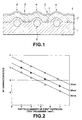
- Fig.1 is a cross-sectional view showing a structural example of a magnetic recording medium according to the present invention.
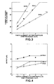
- Fig.2 is a graph showing the relation between the density of a first particle internally added in the non-magnetic substrate and RF characteristics, as affirmed by an experiment 1.
- Fig.3 is a graph showing the relation between the density of the first particle and the number of passes until clogging.
- Fig.4 is a graph showing the relation between the density of the first particle and the output level-down.
- Fig.5 is a graph showing the relation between the density of a second particle dispersed on the nonmagnetic substrate and still characteristics.
- Fig.6 is a graph showing the relation between the density of the second particle and RF characteristics.
- Fig.7 is a graph showing the relation between the density of a first particle internally added in the non-magnetic substrate and RF characteristics, as affirmed by an experiment 2.
- Fig.8 is a graph showing the relation between the density of the first particle and the number of passes until clogging in the experiment 2.
- Fig.9 is a graph showing the relation between the density of the first particle and the output level-down in the experiment 2.
- Fig.10 is a graph showing the relation between the density of a first particle internally added in the non-magnetic substrate and RF characteristics, as affirmed by an experiment 3.
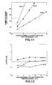
- Fig.11 is a graph showing the relation between the density of the first particle and the number of passes until clogging in the experiment 3.
- Fig.12 is a graph showing the relation between the density of the first particle and the output level-down in the experiment 3.
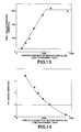
- Fig.13 is a graph showing the relation between the density of a second particle dispersed on the nonmagnetic substrate and still characteristics in the experiment 3.
- Fig.14 is a graph showing the relation between the density of the second particle and RF characteristics in the experiment 3.
- Fig.15 is a graph showing the relation between the density of a first particle internally added in the non-magnetic substrate and RF characteristics, as affirmed by an experiment 4.
- Fig.16 is a graph showing the relation between the density of the first particle and the number of passes until clogging in the experiment 4.
- Fig.17 is a graph showing the relation between the density of the first particle and the output level-down in the experiment 4.
- Fig.18 is a graph showing the relation between the density of a second particle dispersed on the nonmagnetic substrate and still characteristics in the experiment 4.
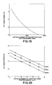
- Fig.19 is a graph showing the relation between the density of the second particle and RF characteristics in the experiment 4.
- Fig.20 is a graph showing the relation between the density of a first particle internally added in the non-magnetic substrate and RF characteristics, as affirmed by an experiment 5.
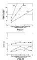
- Fig.21 is a graph showing the relation between the density of the first particle and the number of passes until clogging in the experiment 5.
- Fig.22 is a graph showing the relation between the density of the first particle and the output level-down in the experiment 5.
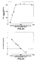
- Fig.23 is a graph showing the relation between the density of a second particle dispersed on the non-magnetic substrate and still characteristics in the experiment 5.
- Fig.24 is a graph showing the relation between the density of the second particle and RF characteristics in the experiment 5.
- the present invention is applied to a so-called thin magnetic film type magnetic recording medium in which a thin magnetic metal film is formed as a magnetic layer on a non-magnetic substrate, which may be a plastic film or the like.
- a thin magnetic metal film is formed as a magnetic layer on a non-magnetic substrate, which may be a plastic film or the like.
- ferromagnetic materials such as Co, Co-Cr, Co-Ni, Co-Fe-Ni or Co-Ni-Cr, may be employed.
- the vacuum thin film forming technique may be recited, and any of the vacuum deposition method, sputtering method and the ion plating method, may be employed.
- the surface properties may be controlled by forming surface protrusions on the surface of the magnetic recording medium for improving its running characteristics.
- the surface protrusions are formed, the spacing loss is correspondingly reduced, with the result that the electro-magnetic conversion characteristics are deteriorated.
- the carbon protective film is formed on the thin magnetic metal film, and two different kinds of surface protrusions are formed on the surface of the carbon protective film for controlling the surface properties of the magnetic recording medium.
- the magnetic recording medium may be improved in running durability without substantially deteriorating its electro-magnetic conversion characteristics.
- the thickness of the carbon protective film is less than 3 nm, there is only minor effect in improving the durability, whereas, if it exceeds 30 nm, the spacing loss is increased and the electro-magnetic conversion characteristics are deteriorated.
- the spacing loss equal to -74 ⁇ d/ ⁇ (dB) is produced, such that, with the thickness of the carbon protective film of 30 nm, the spacing loss amounts to approximately 4.5 dB. Consequently, it is not desirable to increase the thickness of the carbon protective film further.
- the combination of the thickness of the carbon protective film, the height and the density of the first surface protrusions and the height and the density of the second surface protrusions. is outside the above range, the running durability or the electro-magnetic conversion characteristics is deteriorated. For this reason, the above limitations are imposed on the height and the density of the first surface protrusions and the height and the density of the second surface protrusions.
- the magnetic recording medium having the first and second surface protrusions is fabricated using the particles having the particle sizes corresponding to the heights of the respective surface protrusions.
- the non-magnetic substrate is fabricated by dispersing the first particles having the particle size of 65 ⁇ 15 nm in the starting material for the non-magnetic substrate (chip), surface protrusions are produced, which have a height corresponding to the particle diameter, if the protruding extent of the first particle is summed to the thickness of the resin coating formed thereon.
- the amount of addition of the first particles to the starting material is adjusted so that the density of the surface protrusions protruded on the surface of the non-magnetic substrate is comprised within the above range.
- the second particles having the particle size of 18 nm ⁇ 5 nm are arranged on the non-magnetic substrate and fixed using a resin binder. In this manner, the non-magnetic substrate having two different kinds of surface protrusions of 65 nm ⁇ 15 nm and 18 nm ⁇ 5 nm is produced.
- the shape of the protrusions on the non-magnetic substrate is reflected on the surface of the thin magnetic metal film.
- the carbon protective film is formed thereon, the shape of the protrusions on the thin magnetic metal film is reflected on the surface of the carbon protective film.
- the accuracy with which the shape of the protrusions in the non-magnetic substrate is reflected on the surface of the carbon protective film depends on the thickness of the thin magnetic metal film and that of the carbon protective film. Since the shape of the protrusions in the non-magnetic substrate is reflected on the surface with higher accuracy if the two films are of reduced thicknesses, the thicknesses of the thin magnetic metal film and the carbon protective film are desirably set in view of the properties thereof in reflecting the shape of the protrusions.
- the non-magnetic substrate having a planar surface may be employed, and the first and second particles may be arranged with the respective densities on the surface of the thin magnetic metal film, with the protrusions being retained in position by a carbon protective film applied thereon.
- the particles forming the surface protrusions may be those of SiO 2 , TiO 2 , Al 2 O 3 or CaCO 3 or aqueous or non-aqueous emulsions thereof.
- latexes may also be employed.
- thermoplastic resins inclusive of homopolymers or copolymers of vinyl acetate, acrylates, methacrylates, vinylidene chloride, vinyl chloride, ethylene or styrene, thermosetting resins, such as epoxy resins, or synthetic rubber, such as butadiene-styrene copolymers or butadiene-acrylonitrile copolymers.
- any of those used in the thin magnetic metal magnetic recording medium may be employed.
- CrO 2 , Al 2 O 3 , oxides of BN and Co, MgO, SiO 2 , Si 3 O 4 , SiN X , SiC, SiN X -SiO 2 , ZrO 2 , TiO 2 or TiC may be employed besides carbon.
- the film may be formed as a sole film, a multi-layered film or a composite film by vacuum thin film forming techniques.
- An underlying layer, a back coat layer or a top layer may optionally be formed on the non-magnetic substrate, if so desired.
- a lubricant film is desirably formed on the carbon protective film.
- the magnetic recording medium of the present embodiment (magnetic tape) has a thin-film magnetic layer 2, having a thickness of 0.5 ⁇ m or less, formed on a non-magnetic substrate 1, and a carbon protective film 3 formed on the magnetic layer 2, as shown in Fig.1.
- first surface protrusions 4 of a larger size and second surface protrusions 5 of a smaller size are formed on the non-magnetic substrate 1 .
- the first surface protrusions 4 were formed by internally adding SiO 2 particles as first particles of a larger particle size 6 in the non-magnetic substrate 1 for reflecting the particle shape of the first particles 6 on the surface of the non-magnetic substrate 1.
- the first particles 6 are suitably dispersed within the inside of the non-magnetic substrate 1. However, the first particles 6 are locally agglomerated together.
- the second surface protrusions 5 were formed by dispersing SiO 2 particles as the second particles of a smaller particle size 7 on the non-magnetic substrate 1 and fixing them using a binder resin or the like. These first particles were suitably dispersed on the first non-magnetic substrate 1 so as to provide the desired density of the protrusions.
- the thin magnetic metal film was formed, such as by vacuum deposition, for forming the magnetic layer 2.
- the carbon protective film 3 of diamond-like carbon was formed to a film thickness of 3 nm to 30 nm, such as by sputtering, and a lubricant was applied on the surface of the carbon protective film 3 to produce the magnetic tape.
- magnetic tape samples were prepared in which, for the carbon protective film 3 having the thickness of 3 to 7 nm, 7 to 15 nm and 15 to 30 nm, the first particles 6 having the particle size of 35 nm ⁇ 15 nm, 65 nm ⁇ 15 nm and 95 nm ⁇ 15 nm and the second particles 7 having the particle size of 18 nm ⁇ 5 nm and 28 nm ⁇ 5 nm were used, and the two particles were changed in density values.
- the thickness of the carbon protective film 3 was set to 3 to 7 nm, while the particle size of the second particles 7 was set to 18 nm ⁇ 5 nm, and the optimum combination of the particle size and the particle density of the first particles was checked
- First magnetic tape samples were prepared in which the first particles 6 having three different particle sizes of 35 nm ⁇ 15 nm, 65 nm ⁇ 15 nm and 95 nm ⁇ 15 nm were changed in particle density, and measurements were made of the relation between the particle density and the RF characteristics. The results are shown in Fig.2.
- the thickness of the carbon protective film 3 was set to 7 nm, which is the thickness which leads to the severest deterioration of the output within the range of the condition of the present experiment.
- the particle density needs to be set to 7.0 ⁇ 10 4 /mm 2 or less, 6.0 ⁇ 10 4 /mm 2 or less and 4.8 ⁇ 10 4 /mm 2 or less, for the particle size of the first particles 6 of 35 nm ⁇ 15 nm, 65 nm ⁇ 15 nm and 95 nm ⁇ 15 nm, respectively.
- the number of passes up to clogging is the number of passes until the first one of the five decks undergoes clogging and the thickness of the carbon protective film 3 was set to 3 nm, which is the thickness most liable to clogging within the range of the condition of the present experiment.
- the particle density it is necessary for the particle density to be not less than 3.0 ⁇ 10 4 /mm 2 , not less than 1.5 ⁇ 10 4 /mm 2 and not less than 1.2 ⁇ 10 4 /mm 2 , for the particle size of the first particle 6 of 35 nm ⁇ 15 nm, 65 nm ⁇ 15 nm and 95 nm ⁇ 15 nm, respectively.
- the particle density is 3.0 to 7.0 ⁇ 10 4 /mm 2 , 1.5 to 6.0 ⁇ 10 4 /mm 2 and 1.2 to 4.8 ⁇ 10 4 /mm 2 , for the particle size of the first particle 6 of 35 nm ⁇ 15 nm, 65 nm ⁇ 15 nm and 95 nm ⁇ 15 nm, respectively.
- the power level-down is significant even within the above range of the particle density, such that, if the lower limit of the power level-down is set to -2.25 dB, the magnetic tape becomes unusable.
- the particle having the particle size of 65 nm ⁇ 15 nm is used, sufficient characteristics may be achieved within the above range of the particle density. It is noted that the power level-down value is not dependent on the thickness of the carbon protective film 3.
- the second particle 7 having the particle size of 18 nm ⁇ 5 nm it is preferred to use the first particle 6 having the particle size of 65 nm ⁇ 15 nm with the particle density of 1.5 to 6.0 ⁇ 10 4 /mm 2 .
- the still characteristics were defined as the average time in minutes until clogging occurred in eight magnetic heads, while the thickness of the carbon protective film 3 was set to 3 nm which is the value corresponding to the worst value of still characteristics within the range of the condition of the present experiment.
- Fig.5 shows the relation of the particle density of the second particle 7 versus the still characteristics. Meanwhile, the results are shown in Fig.5 along with the results obtained with the samples used in the experiment 2 in which the particle size of the second particle 7 is set to 28 nm. The data for the present experiment in Fig.5 is that with the indication of 18 nm.
- the density of the second particle 7 so as to be 500 to 4500 ⁇ 10 4 /mm 2 .
- the relation between the particle density and RF characteristics was checked for magnetic tape samples in which the first particles 6 having three particle size ranges of 35 nm ⁇ 15 nm, 65 nm ⁇ 15 nm and 95 nm ⁇ 15 nm were changed in the particle density.
- the results are shown in Fig.7.
- the thickness of the carbon protective film 3 was set to 7 nm which is the value corresponding to the worst value of still characteristics within the range of the condition of the present experiment.
- the particle density needs to be set to 6.0 ⁇ 10 4 /mm 2 or less, 5.0 ⁇ 10 4 /mm 2 or less and 4.0 ⁇ 10 4 /mm 2 or less, for the particle size of the first particles 6 of 35 nm ⁇ 15 nm, 65 nm ⁇ 15 nm and 95 nm ⁇ 15 nm, respectively.
- the number of passes up to clogging is the number of passes until the first one of the five decks underwent the clogging, and the thickness of the carbon protective film 3 was set to 3 nm, which is the thickness most liable to clogging within the range of the condition of the present experiment.
- the particle density it is necessary for the particle density to be not less than 2.0 ⁇ 10 4 /mm 2 , not less than 1.1 ⁇ 10 4 /mm 2 and not less than 1.0 ⁇ 10 4 /mm 2 , for the particle size of the first particle 6 of 35 nm ⁇ 15 nm, 65 nm ⁇ 15 nm and 95 nm ⁇ 15 nm, respectively.
- the particle density is 2.0 to 6.0 ⁇ 10 4 /mm 2 , 1.1 to 5.0 ⁇ 10 4 /mm 2 and 1.0 to 4.0 ⁇ 10 4 /mm 2 , for the particle size of the first particle 6 of 35 nm ⁇ 15 nm, 65 nm ⁇ 15 nm and 95 nm ⁇ 15 nm, respectively.
- the output level-down becomes significant even within the above range of the particle size and, if the lower limit of the output level-down is set to -2.25 dB, the resulting tape becomes unusable.
- the first particles 6 having the particle size range of 65 nm ⁇ 15 nm or 95 nm ⁇ 15 nm are used, a sufficient output level may be achieved within the above-mentioned particle density range. Meanwhile, the output level-down is not dependent upon the thickness of the carbon protective film 3.
- the second particles 7 having the particle size of 28 nm ⁇ 5 nm are used, it is desirable to use the first particles 6 having the particle size of 65 nm ⁇ 15 nm or 95 ⁇ 15 nm with the particle density of 1.1 to 5.0 ⁇ 10 4 /mm 2 or 1.0 to 4.0 ⁇ 10 4 /mm 2 , respectively.
- the still characteristics were defined as the average time in minutes until clogging occurred in eight magnetic heads, while the thickness of the carbon protective film 3 was set to 3 nm which is the value corresponding to the worst value of still characteristics within the range of the condition of the present experiment.
- Fig.5 shows the relation of the particle density of the second particle 7 versus the still characteristics. Meanwhile, the results are shown in Fig.5 along with the results obtained with the samples used in the experiment 1 in which the particle size of the second particle 7 is set to 18 nm. The data for the present experiment in Fig.5 is that with the indication of 28 nm.
- Fig.6 also shows the relation between the density of the second particles 7 and RF characteristics.
- the relation between the particle density of the second particle 7 and RF characteristics is shown in Fig.6.
- the thickness of the carbon protective film 3 was set to 7 nm which is the value corresponding to the worst output value within the range of the condition of the present experiment.
- the above relation with the use of the first particles 6 having the particle size of 65 nm ⁇ 15 nm is shown by a curve b
- that with the use of the second particles 7 having the particle size of 95 nm ⁇ 15 nm is shown by a curve c in Fig.6.
- the density of the second particles 7 has to be set so as to be 4000 ⁇ 10 4 /mm 2 and 3500 ⁇ 10 4 /mm 2 for the particle size of the first particle 6 of 65 nm ⁇ 15 nm and 95 nm ⁇ 15 nm, respectively.
- the density of the second particles 7 is set to 400 to 4000 ⁇ 10 4 /mm 2 and to 400 to 3500 ⁇ 10 4 /mm 2 for the particle size of the first particles 6 of 65 nm ⁇ 15 nm and 95 nm ⁇ 15 nm, respectively.
- Fig.6 the data obtained with the use of the second particles 7 having the particle size of 18 nm ⁇ 5 nm in the above experiment 1 are also shown by the curve a . It may be seen that the data shown by the curve a are slightly superior in RF characteristics to the data obtained with the usee of the second particles 7 having the particle size of 28 nm ⁇ 5 nm shown by the curves b and c .
- the desirable particle size and the desirable particle density of the first particle were checked.
- the thickness of the carbon protective film 3 was set to 15 nm which is the value corresponding to the worst output value within the range of the condition of the present experiment.
- the particle density needs to be set to 5.0 ⁇ 10 4 /mm 2 or less, 4.0 ⁇ 10 4 /mm 2 or less and 2.8 ⁇ 10 4 /mm 2 or less, for the particle size of the first particles 6 of 35 ⁇ 15 nm, 65 ⁇ 15 nm and 95 ⁇ 15 nm, respectively.
- the number of passes up to clogging is the number of passes until the first one of the five decks underwent the clogging, and the thickness of the carbon protective film 3 was set to 7 nm, which is the thickness most liable to clogging within the range of the condition of the present experiment.
- the particle density it is necessary for the particle density to be not less than 2.0 ⁇ 10 4 /mm 2 , not less than 1.0 ⁇ 10 4 /mm 2 and not less than 0.7 ⁇ 10 4 /mm 2 , for the particle size of the first particle 6 of 35 nm ⁇ 15 nm, 65 nm ⁇ 15 nm and 95 nm ⁇ 15 nm, respectively.
- the particle density is 2.0 to 5.0 ⁇ 10 4 /mm 2 , 1.0 to 4.0 ⁇ 10 4 /mm 2 and 0.7 to 2.8 ⁇ 10 4 /mm 2 , for the particle size of the first particle 6 of 35 nm ⁇ 15 nm, 65 nm ⁇ 15 nm and 95 nm ⁇ 15 nm, respectively.
- the output level-down becomes significant even within the above range of the particle size and, if the lower limit of the output level-down is set to -2.25 dB, the resulting tape becomes unusable.
- the first particles 6 having the particle size range of 65 nm ⁇ 15 nm are used, a sufficient output level may be achieved within the above-mentioned particle density range. Meanwhile, the output level-down is not dependent upon the thickness of the carbon protective film 3.
- the second particles 7 having the particle size of 18 nm ⁇ 5 nm are used, it is desirable to use the first particles 6 having the particle size of 65 nm ⁇ 15 nm with the particle density of 1.0 to 4.0 ⁇ 10 4 /mm 2 .
- the still characteristics were defined as the average time in minutes until clogging occurred in eight magnetic heads, while the thickness of the carbon protective film 3 was set to 7 nm which is the value corresponding to the worst value of still characteristics within the range of the condition of the present experiment.
- the relation between the particle density of the second particle 7 and RF characteristics is shown in Fig.14.
- the thickness of the carbon protective film 3 was set to 15 nm which is the value corresponding to the worst output value within the range of the condition of the present experiment.
- the density of the second particles 7 has to be set so as to be not higher than 2500 ⁇ 10 4 /mm 2 .
- the density of the second particles has to be set to 400 to 2500 ⁇ 10 4 /mm 2 .
- the desirable particle size and the desirable particle density of the first particle were checked.
- the relation between the particle density and RF characteristics was checked for magnetic tape samples in which the first particles 6 having three particle size ranges of 35 nm ⁇ 15 nm, 65 nm ⁇ 15 nm and 95 nm ⁇ 15 nm were changed in the particle density.
- the results are shown in Fig.15.
- the thickness of the carbon protective film 3 was set to 15 nm which is the value corresponding to the worst output value within the range of the condition of the present experiment.
- the particle density needs to be set to 5.0 ⁇ 10 4 /mm 2 or less, 4.0 ⁇ 10 4 /mm 2 or less and 2.8 ⁇ 10 4 /mm 2 or less, for the particle size of the first particles 6 of 35 nm ⁇ 15 nm, 65 nm ⁇ 15 nm and 95 nm ⁇ 15 nm, respectively.
- the number of passes up to clogging is the number of passes until the first one of the five decks underwent clogging and the thickness of the carbon protective film 3 was set to 7 nm, which is the thickness most liable to clogging within the range of the condition of the present experiment.
- the particle density it is necessary for the particle density to be not less than 2.0 ⁇ 10 4 /mm 2 , not less than 1.0 ⁇ 10 4 /mm 2 and not less than 0.7 ⁇ 10 4 /mm 2 , for the particle size of the first particle 6 of 35 ⁇ 15 nm, 65 ⁇ 15 and 95 ⁇ 15 nm, respectively.
- the particle density is 2.0 to 5.0 ⁇ 10 4 /mm 2 , 1.0 to 4.0 ⁇ 10 4 /mm 2 and 0.7 to 2.8 ⁇ 10 4 /mm 2 , for the particle size of the first particle 6 of 35 nm ⁇ 15 nm, 65 nm ⁇ 15 nm and 95 nm ⁇ 15 nm, respectively.
- the second particle 7 having the particle size of 28 nm ⁇ 5 nm it is preferred to use the first particle 6 having the particle size of 95 nm ⁇ 15 nm with the particle density of 0.7 to 2.8 ⁇ 10 4 /mm 2 .
- the still characteristics were defined as the average time in minutes until clogging occurred in eight magnetic heads, while the thickness of the carbon protective film 3 was set to 7 nm which is the value corresponding to the worst value of still characteristics within the range of the condition of the present experiment.
- Fig.19 shows the relation between the particle density of the second particles 7 and RF characteristics.
- the thickness of the carbon protective film 3 was set to 15 nm which is the value corresponding to the worst output value within the range of the condition of the present experiment.
- the density of the second particles 7 has to be set to not higher than 2000 ⁇ 10 4 /mm 2 .
- the density of the second particle 7 so as to be 400 to 2000 ⁇ 10 4 /mm 2 .
- the desirable particle size and the desirable particle density of the first particle were checked.
- the relation between the particle density and RF characteristics was checked for magnetic tape samples in which the first particles 6 having three particle size ranges of 35 nm ⁇ 15 nm, 65 nm ⁇ 15 nm and 95 nm ⁇ 15 nm were changed in the particle density.
- the results are shown in Fig.20.
- the thickness of the carbon protective film 3 was set to 30 nm which is the value corresponding to the worst output value within the range of the condition of the present experiment.
- the particle density needs to be set to 4.0 ⁇ 10 4 /mm 2 or less, 3.0 ⁇ 10 4 /mm 2 or less and 2.0 ⁇ 10 4 /mm 2 or less, for the particle size of the first particles 6 of 35 nm ⁇ 15 nm, 65 nm ⁇ 15 nm and 95 nm ⁇ 15 nm, respectively.
- the number of passes up to clogging is the number of passes until the first one of the five decks underwent the clogging, and the thickness of the carbon protective film 3 was set to 15 nm, which is the thickness most liable to clogging within the range of the condition of the present experiment.
- the particle density it is necessary for the particle density to be not less than 2.0 ⁇ 10 4 /mm 2 , not less than 1.0 ⁇ 10 4 /mm 2 and not less than 0.7 ⁇ 10 4 /mm 2 , for the particle size of the first particle 6 of 35 nm ⁇ 15 nm, 65 nm ⁇ 15 nm and 95 nm ⁇ 15 nm, respectively.
- the output level-down becomes significant even within the above range of the particle size, and that, if the lower limit of the output level-down is set to -2.25 dB, the resulting tape becomes unusable.
- the first particles 6 having the particle size range of 65 nm ⁇ 15 nm are used, a sufficient output level may be achieved within the above-mentioned particle density range. Meanwhile, the output level-down is not dependent upon the thickness of the carbon protective film 3.
- the second particles 7 having the particle size of 18 nm ⁇ 5 nm are used, it is desirable to use the first particles 6 having the particle size of 65 nm ⁇ 15 nm with the particle density of 1.0 to 3.0 ⁇ 10 4 /mm 2 .
- the still characteristics were defined as the average time in minutes until clogging occurred in eight magnetic heads, while the thickness of the carbon protective film 3 was set to 15 nm which is the value corresponding to the worst value of still characteristics within the range of the condition of the present experiment.
- Fig.24 shows the relation between the particle density of the second particles 7 and RF characteristics.
- the thickness of the carbon protective film 3 was set to 30 nm, which is the value corresponding to the worst output value within the range of the condition of the present experiment.
- the density of the second particles 7 has to be set to not less than 2000 ⁇ 10 4 /mm 2 .
- the density of the second particles 7 has to be set so as to be 400 to 2000 ⁇ 10 4 /mm 2 or less.
- the first condition is that the carbon protective film has a thickness of 3 to 7 nm, first surface protrusions having the height of 65 nm ⁇ 15 nm are formed on the surface of the carbon protective film at a density of 1.5 ⁇ 10 4 to 6.0 ⁇ 10 4 /mm 2 and second surface protrusions having the height of 18 nm ⁇ 5 nm are formed on the surface of the carbon protective film at a density of 500 ⁇ 10 4 to 4500 ⁇ 10 4 /mm 2 .
- the second condition is that the carbon protective film has a thickness of 3 to 7 nm, first surface protrusions having the height of 65 nm ⁇ 15 nm are formed on the surface of the carbon protective film at a density of 1.1 ⁇ 10 4 to 5.0 ⁇ 10 4 /mm 2 and second surface protrusions having the height of 28 nm ⁇ 5 nm are formed on the surface of the carbon protective film at a density of 400 ⁇ 10 4 to 4000 ⁇ 10 4 /mm 2 .
- the third condition is that the carbon protective film has a thickness of 3 to 7 nm, first surface protrusions having the height of 95 nm ⁇ 15 nm are formed on the surface of the carbon protective film at a density of 1.0 ⁇ 10 4 to 4.0 ⁇ 10 4 /mm 2 and second surface protrusions having the height of 28 nm ⁇ 5 nm are formed on the surface of the carbon protective film at a density of 400 ⁇ 10 4 to 3500 ⁇ 10 4 /mm 2 .
- the fourth condition is that the carbon protective film has a thickness of 7 to 15 nm, first surface protrusions having the height of 65 nm ⁇ 15 nm are formed on the surface of the carbon protective film at a density of 1.0 ⁇ 10 4 to 4.0 ⁇ 10 4 /mm 2 and second surface protrusions having the height of 18 nm ⁇ 5 nm are formed on the surface of the carbon protective film at a density of 400 ⁇ 10 4 to 2500 ⁇ 10 4 /mm 2 .
- the fifth condition is that the carbon protective film has a thickness of 7 to 15 nm, first surface protrusions having the height of 95 nm ⁇ 15 nm are formed on the surface of the carbon protective film at a density of 0.7 ⁇ 10 4 to 2.8 ⁇ 10 4 /mm 2 and second surface protrusions having the height of 28 nm ⁇ 5 nm are formed on the surface of the carbon protective film at a density of 400 ⁇ 10 4 to 2000 ⁇ 10 4 /mm 2 .
- the sixth condition is that the carbon protective film has a thickness of 15 to 30 nm, first surface protrusions having the height of 65 nm ⁇ 15 nm are formed on the surface of the carbon protective film at a density of 1.0 ⁇ 10 4 to 3.0 ⁇ 10 4 /mm 2 and second surface protrusions having the height of 18 nm ⁇ 5 nm are formed on the surface of the carbon protective film at a density of 400 ⁇ 10 4 to 2000 ⁇ 10 4 /mm 2 .
- the present invention provides a magnetic recording medium having a thin magnetic metal layer and a carbon protective layer formed on the non-magnetic substrate, in which two different kinds of protrusion having different depths are formed on the carbon protective film to a pre-set density for controlling the surface properties of the recording medium, it becomes possible to prevent the electro-magnetic conversion characteristics of the recording medium from being lowered due to the spacing loss, thereby improving its running durability.
Landscapes
- Chemical & Material Sciences (AREA)
- Inorganic Chemistry (AREA)
- Magnetic Record Carriers (AREA)
Description
Claims (7)
- A magnetic recording medium comprisingwherein the improvement resides in thata non-magnetic substrate,a thin magnetic metal layer formed on said non-magnetic substrate, anda carbon protective film formed on said thin magnetic metal film,said carbon protective film has a thickness in the range of 3 nm to 30 nm,said carbon protective film presenting first protrusions and second protrusions at respective pre-set densities,said first protrusions having a height in the range of 65 nm ± 15 nm to 95 nm ± 15 nm, andsaid second protrusions having a height in the range of from 18 nm ± 5 nm to 28 ± 5 nm, said respective pre-set densities are fixed such to achieve a pre-set output, a pre-set minimum number of passes of head until clogging, a pre-set minimum output power level-down and pre-set still characteristics.
- The magnetic recording medium as claimed in claim 1 wherein the carbon protective film has a thickness in the range of 3 nm to 7 nm, the first protrusions having a height in the range of 65 nm ± 15 nm are formed on the surface of the carbon protective film at a density of 1.5 × 10⁴/mm2 to 6.0 × 10⁴/mm2 and the second protrusions having a height in the range of 18 nm ± 5 nm are formed on the surface of the carbon protective film at a density of 500 × 104 to 4500 × 104/mm2.
- The magnetic recording medium as claimed in claim 1 wherein the carbon protective film has a thickness in the range of 3 nm to 7 nm, the first protrusions having a height in the range of 65 nm ± 15 nm are formed on the surface of the carbon protective film at a density of 1.1 × 10⁴/mm2 to 5.0 × 10⁴/mm2 and the second protrusions having a height in the range of 28 nm ± 5 nm are formed on the surface of the carbon protective film at a density of 400 × 104 to 4000 × 104/mm2.
- The magnetic recording medium as claimed in claim 1 wherein the carbon protective film has a thickness in the range of 3 nm to 7 nm, the first protrusions having a height in the range of 95 nm ± 15 nm are formed on the surface of the carbon protective film at a density of 1.0 × 10⁴/mm2 to 4.0 x 10⁴/mm2 and the second protrusions having a height in the range of 28 nm ± 5 nm are formed on the surface of the carbon protective film at a density of 400 × 104/ mm2 to 3500 × 104/mm2.
- The magnetic recording medium as claimed in claim 1 wherein the carbon protective film has a thickness in the range of 7 nm to 15 nm, the first protrusions having a height in the range of 65 nm ± 15 nm are formed on the surface of the carbon protective film at a density of 1.0 × 10⁴/mm2 to 4.0 × 10⁴/mm2 and the second protrusions having a height in the range of 18 nm ± 5 nm are formed on the surface of the carbon protective film at a density of 400 × 104 to 2500 × 104/mm2.
- The magnetic recording medium as claimed in claim 1 wherein the carbon protective film has a thickness in the range of 7 nm to 15 nm, the first protrusions having a height in the range of 95 nm ± 15 nm are formed on the surface of the carbon protective film at a density of 0.7 × 10⁴/mm2 to 2.8 x 10⁴/mm2 and the second protrusions having a height in the range of 28 nm ± 5 nm are formed on the surface of the carbon protective film at a density of 400 × 104 to 2000 × 104/mm2.
- The magnetic recording medium as claimed in claim 1 wherein the carbon protective film has a thickness in the range of 15 nm to 30 nm, the first protrusions having a height in the range of 65 nm ± 15 nm are formed on the surface of the carbon protective film at a density of 1.0 × 10⁴/mm2 to 3.0 × 10⁴/mm2 and the second protrusions having a height in the range of 18 nm ± 5 nm are formed on the surface of the carbon protective film at a density of 400 × 104 to 2000 × 104/mm2.
Applications Claiming Priority (2)
| Application Number | Priority Date | Filing Date | Title |
|---|---|---|---|
| JP127518/93 | 1993-05-28 | ||
| JP5127518A JPH06338049A (en) | 1993-05-28 | 1993-05-28 | Magnetic recording medium |
Publications (2)
| Publication Number | Publication Date |
|---|---|
| EP0626677A1 EP0626677A1 (en) | 1994-11-30 |
| EP0626677B1 true EP0626677B1 (en) | 1998-01-28 |
Family
ID=14962001
Family Applications (1)
| Application Number | Title | Priority Date | Filing Date |
|---|---|---|---|
| EP94107618A Expired - Lifetime EP0626677B1 (en) | 1993-05-28 | 1994-05-17 | Magnetic recording medium |
Country Status (5)
| Country | Link |
|---|---|
| US (1) | US5662984A (en) |
| EP (1) | EP0626677B1 (en) |
| JP (1) | JPH06338049A (en) |
| KR (1) | KR100278790B1 (en) |
| DE (1) | DE69408203T2 (en) |
Families Citing this family (3)
| Publication number | Priority date | Publication date | Assignee | Title |
|---|---|---|---|---|
| JPH117622A (en) * | 1997-04-25 | 1999-01-12 | Hitachi Ltd | Magnetic recording medium substrate, magnetic recording medium, and method of manufacturing magnetic recording medium |
| US6251496B1 (en) * | 1997-12-16 | 2001-06-26 | Matsushita Electric Industrial Co., Ltd. | Magnetic recording medium method and apparatus for producing the same |
| JP2005327368A (en) * | 2004-05-14 | 2005-11-24 | Fujitsu Ltd | Protective layer for magnetic recording device, magnetic head, and magnetic recording device |
Family Cites Families (10)
| Publication number | Priority date | Publication date | Assignee | Title |
|---|---|---|---|---|
| EP0061769B1 (en) * | 1981-03-30 | 1987-04-01 | Teijin Limited | Magnetic recording medium |
| US4540618A (en) * | 1982-08-12 | 1985-09-10 | Matsushita Electric Industrial Co., Ltd. | Magnetic recording medium |
| EP0109667B1 (en) * | 1982-11-19 | 1987-04-01 | Matsushita Electric Industrial Co., Ltd. | Magnetic recording medium |
| US4639389A (en) * | 1983-12-12 | 1987-01-27 | Tdk Corporation | Magnetic recording medium |
| JPS6111921A (en) * | 1984-06-27 | 1986-01-20 | Tdk Corp | Magnetic recording medium and magnetic recording method |
| JPS6139921A (en) * | 1984-07-31 | 1986-02-26 | Tdk Corp | Magnetic recording medium and magnetic recording method |
| JPS6142724A (en) * | 1984-08-03 | 1986-03-01 | Tdk Corp | Magnetic recording medium and magnetic recording method |
| JPH0795369B2 (en) * | 1985-12-25 | 1995-10-11 | 株式会社東芝 | Perpendicular magnetic recording medium |
| JP2792068B2 (en) * | 1987-05-01 | 1998-08-27 | 東レ株式会社 | Polyester film and magnetic recording medium |
| JPH0675287B2 (en) * | 1987-10-07 | 1994-09-21 | 富士写真フイルム株式会社 | Magnetic recording medium |
-
1993
- 1993-05-28 JP JP5127518A patent/JPH06338049A/en active Pending
-
1994
- 1994-05-17 EP EP94107618A patent/EP0626677B1/en not_active Expired - Lifetime
- 1994-05-17 DE DE69408203T patent/DE69408203T2/en not_active Expired - Fee Related
- 1994-05-25 KR KR1019940011343A patent/KR100278790B1/en not_active Expired - Fee Related
- 1994-05-27 US US08/250,432 patent/US5662984A/en not_active Expired - Lifetime
Also Published As
| Publication number | Publication date |
|---|---|
| KR100278790B1 (en) | 2001-01-15 |
| JPH06338049A (en) | 1994-12-06 |
| EP0626677A1 (en) | 1994-11-30 |
| DE69408203D1 (en) | 1998-03-05 |
| DE69408203T2 (en) | 1998-08-27 |
| US5662984A (en) | 1997-09-02 |
Similar Documents
| Publication | Publication Date | Title |
|---|---|---|
| EP0409216B1 (en) | Use of magnetic recording media for recording a video signal | |
| US4671993A (en) | Magnetic recording medium | |
| US4701364A (en) | Tape for cleaning magnetic head | |
| US5662984A (en) | Magnetic recording medium | |
| US4614687A (en) | Magnetic recording medium | |
| US5057364A (en) | Magnetic recording medium | |
| US5686177A (en) | Magnetic recording medium | |
| EP0531514B1 (en) | A magnetic head for high-frequency, high-density recording | |
| EP0494793B1 (en) | Magnetic recording medium with improved backside coating | |
| US5218499A (en) | Thin-film magnetic head for perpendicular magnetic recording having a magnetic member with grooves crossing at right angles formed in a principal surface thereof | |
| US5013616A (en) | Magnetic recording medium of thin metal film type | |
| US5525419A (en) | Magnetic recording medium | |
| US4837080A (en) | Magnetic recording mediums for high density recording comprising an improved structure of a magnetic layer | |
| US6120877A (en) | Magnetic recording medium | |
| EP0642120B1 (en) | Magnetic recording medium | |
| US5037695A (en) | Magnetic recording medium | |
| JP2888488B2 (en) | Magnetic recording media | |
| EP0700035B1 (en) | Magnetic recording medium | |
| JPH09237417A (en) | Magnetic recording media | |
| JP2644264B2 (en) | Magnetic recording media | |
| JPH05205237A (en) | Magnetic recording medium | |
| JPH06309643A (en) | Magnetic recording medium | |
| JP2877118B2 (en) | Magnetic recording media | |
| JPH08235558A (en) | Magnetic recording media | |
| JPH06314422A (en) | Magnetic recording medium |
Legal Events
| Date | Code | Title | Description |
|---|---|---|---|
| PUAI | Public reference made under article 153(3) epc to a published international application that has entered the european phase |
Free format text: ORIGINAL CODE: 0009012 |
|
| AK | Designated contracting states |
Kind code of ref document: A1 Designated state(s): DE FR GB |
|
| 17P | Request for examination filed |
Effective date: 19950428 |
|
| 17Q | First examination report despatched |
Effective date: 19961023 |
|
| GRAG | Despatch of communication of intention to grant |
Free format text: ORIGINAL CODE: EPIDOS AGRA |
|
| GRAG | Despatch of communication of intention to grant |
Free format text: ORIGINAL CODE: EPIDOS AGRA |
|
| GRAH | Despatch of communication of intention to grant a patent |
Free format text: ORIGINAL CODE: EPIDOS IGRA |
|
| GRAH | Despatch of communication of intention to grant a patent |
Free format text: ORIGINAL CODE: EPIDOS IGRA |
|
| GRAA | (expected) grant |
Free format text: ORIGINAL CODE: 0009210 |
|
| AK | Designated contracting states |
Kind code of ref document: B1 Designated state(s): DE FR GB |
|
| REF | Corresponds to: |
Ref document number: 69408203 Country of ref document: DE Date of ref document: 19980305 |
|
| ET | Fr: translation filed | ||
| PLBE | No opposition filed within time limit |
Free format text: ORIGINAL CODE: 0009261 |
|
| STAA | Information on the status of an ep patent application or granted ep patent |
Free format text: STATUS: NO OPPOSITION FILED WITHIN TIME LIMIT |
|
| 26N | No opposition filed | ||
| REG | Reference to a national code |
Ref country code: GB Ref legal event code: IF02 |
|
| PGFP | Annual fee paid to national office [announced via postgrant information from national office to epo] |
Ref country code: DE Payment date: 20080522 Year of fee payment: 15 |
|
| PGFP | Annual fee paid to national office [announced via postgrant information from national office to epo] |
Ref country code: GB Payment date: 20080521 Year of fee payment: 15 |
|
| GBPC | Gb: european patent ceased through non-payment of renewal fee |
Effective date: 20090517 |
|
| REG | Reference to a national code |
Ref country code: FR Ref legal event code: ST Effective date: 20100129 |
|
| PG25 | Lapsed in a contracting state [announced via postgrant information from national office to epo] |
Ref country code: FR Free format text: LAPSE BECAUSE OF NON-PAYMENT OF DUE FEES Effective date: 20090602 |
|
| PGFP | Annual fee paid to national office [announced via postgrant information from national office to epo] |
Ref country code: FR Payment date: 20080514 Year of fee payment: 15 |
|
| PG25 | Lapsed in a contracting state [announced via postgrant information from national office to epo] |
Ref country code: GB Free format text: LAPSE BECAUSE OF NON-PAYMENT OF DUE FEES Effective date: 20090517 |
|
| PG25 | Lapsed in a contracting state [announced via postgrant information from national office to epo] |
Ref country code: DE Free format text: LAPSE BECAUSE OF NON-PAYMENT OF DUE FEES Effective date: 20091201 |