EP0625703A1 - Surface inspection apparatus for spherical objects - Google Patents
Surface inspection apparatus for spherical objects Download PDFInfo
- Publication number
- EP0625703A1 EP0625703A1 EP94303564A EP94303564A EP0625703A1 EP 0625703 A1 EP0625703 A1 EP 0625703A1 EP 94303564 A EP94303564 A EP 94303564A EP 94303564 A EP94303564 A EP 94303564A EP 0625703 A1 EP0625703 A1 EP 0625703A1
- Authority
- EP
- European Patent Office
- Prior art keywords
- support
- spherical
- matter
- unit
- inspection
- Prior art date
- Legal status (The legal status is an assumption and is not a legal conclusion. Google has not performed a legal analysis and makes no representation as to the accuracy of the status listed.)
- Withdrawn
Links
- 238000007689 inspection Methods 0.000 title claims abstract description 87
- 229910000831 Steel Inorganic materials 0.000 claims abstract description 18
- 239000010959 steel Substances 0.000 claims abstract description 18
- 230000007547 defect Effects 0.000 claims abstract description 17
- 230000002093 peripheral effect Effects 0.000 claims abstract description 5
- 238000000034 method Methods 0.000 claims description 5
- 230000000284 resting effect Effects 0.000 claims 1
- 238000012797 qualification Methods 0.000 abstract description 4
- 125000006850 spacer group Chemical group 0.000 description 9
- 239000007788 liquid Substances 0.000 description 7
- 239000000470 constituent Substances 0.000 description 4
- 230000002950 deficient Effects 0.000 description 4
- 238000001514 detection method Methods 0.000 description 4
- 238000010586 diagram Methods 0.000 description 4
- 230000000694 effects Effects 0.000 description 4
- 239000013307 optical fiber Substances 0.000 description 4
- 230000005540 biological transmission Effects 0.000 description 3
- 239000000919 ceramic Substances 0.000 description 2
- 150000001875 compounds Chemical class 0.000 description 2
- JEIPFZHSYJVQDO-UHFFFAOYSA-N iron(III) oxide Inorganic materials O=[Fe]O[Fe]=O JEIPFZHSYJVQDO-UHFFFAOYSA-N 0.000 description 2
- 239000000463 material Substances 0.000 description 2
- 239000002184 metal Substances 0.000 description 2
- 239000004033 plastic Substances 0.000 description 2
- 230000003449 preventive effect Effects 0.000 description 2
- 239000004575 stone Substances 0.000 description 2
- 230000005856 abnormality Effects 0.000 description 1
- 238000010276 construction Methods 0.000 description 1
- 230000003247 decreasing effect Effects 0.000 description 1
- 230000002708 enhancing effect Effects 0.000 description 1
- 239000000203 mixture Substances 0.000 description 1
- 238000005096 rolling process Methods 0.000 description 1
Images




Classifications
-
- G—PHYSICS
- G01—MEASURING; TESTING
- G01N—INVESTIGATING OR ANALYSING MATERIALS BY DETERMINING THEIR CHEMICAL OR PHYSICAL PROPERTIES
- G01N21/00—Investigating or analysing materials by the use of optical means, i.e. using sub-millimetre waves, infrared, visible or ultraviolet light
- G01N21/84—Systems specially adapted for particular applications
- G01N21/88—Investigating the presence of flaws or contamination
- G01N21/95—Investigating the presence of flaws or contamination characterised by the material or shape of the object to be examined
- G01N21/951—Balls
-
- G—PHYSICS
- G01—MEASURING; TESTING
- G01B—MEASURING LENGTH, THICKNESS OR SIMILAR LINEAR DIMENSIONS; MEASURING ANGLES; MEASURING AREAS; MEASURING IRREGULARITIES OF SURFACES OR CONTOURS
- G01B11/00—Measuring arrangements characterised by the use of optical techniques
- G01B11/24—Measuring arrangements characterised by the use of optical techniques for measuring contours or curvatures
- G01B11/2408—Measuring arrangements characterised by the use of optical techniques for measuring contours or curvatures for measuring roundness
Definitions
- the invention relates to a surface inspection apparatus of spherical matter such as steel balls, other metal balls, ceramic balls, spherical stones, plastic balls and the like.
- sensors cannot be disposed in the bottom of the spherical matter, for example, because it is supported on a holder or a table, which gives rise to necessity of inspecting again by turning upside down after inspecting the upper hemisphere of the spherical matter. If such job is done manually each time, it is impossible to inspect a large quantity of spherical samples efficiently. It is hence a primary object of the invention to solve such problems.
- a surface inspection apparatus of spherical matter according to a first invention comprises an inspection unit 1 possessing electromagnetic sensors such as photo sensors, and a holder 2 for mounting steel balls or other spherical matter, and is constituted as follows.
- the inspection unit 1 detects surface defects of spherical matter put on the holder 2 by a proper number of electromagnetic sensors.
- the holder 2 possesses a rotatable support 20 and an auxiliary support 23 for supporting the spherical matter together with the support 20.
- the support 20 possesses a receiving groove 3 formed in an annular form along its rotating peripheral surface, and this receiving groove 3 can accommodate the vicinity of the bottom of the spherical matter, and the spherical matter is rolled within the receiving groove 3 by the rotation of the support 20, so that the direction of the spherical matter can be changed.
- the auxiliary support 23 is formed separately from the support 20, and disposed near the support 20, and is designed to support the portion of the spherical matter exposed from the receiving groove 3, and holding the spherical matter at specific position.
- the auxiliary support 23 possesses a rotating body 230 in the position contacting with the spherical matter.
- This rotating body 230 can rotate the spherical body in a different direction from the rotating direction of the support 20.
- a surface inspection apparatus of spherical matter in a third invention comprises an inspection unit 1 possessing electromagnetic sensors such as photo sensors, and a holder 2 for mounting steel balls or other spherical matter, and is constituted as follows.
- the inspection unit 1 detects surface defects of spherical matter put on the holder 2 by a proper number of electromagnetic sensors.
- the holder 2 possesses a rotatable first support 21, a rotatable second support 22, and an auxiliary support 23 for supporting the spherical matter together with the first support 21 and second support 22.
- the first support 21 and second support 22 can rotate at mutually different rotating speeds.
- the auxiliary support 23 possesses a rotating body 230 at a position contacting with the spherical matter, and the rotating body 230 provides the spherical matter with a torque in a proper direction.
- a surface inspection apparatus of spherical matter in a fifth invention comprises a feed unit 4 for feeding spherical matter such as steel balls, a transfer unit 26 for transferring the spherical matter supplied from the feed unit 4 for a specific distance, an inspection unit 1 for inspecting the surface of the spherical matter on the transfer unit 24 by using electromagnetic wave such as beam of light, and a sorting unit 5 for sorting the spherical matter sent from the transfer unit 26 depending on the result of inspection by the inspection unit 1.
- the transfer unit 26 has a first support 21 of nearly columnar shape forming the a transfer route for spherical matter, and a second support 22 possessing a longitudinal width at least nearly same as the first support 21, formed as being extended from the feed unit 4 side to the sorting unit 5 side.
- the first support 21 rotates about the symmetrical axis of its own column, and a guide groove 300 extending spirally is formed on its circumference from the end part of the feed unit 4 side to the end part of the sorting unit 5 side.
- the guide groove 300 transfers and guides the spherical matter from the end part of the feed unit 4 side to the end part of the sorting unit 5 side, and sequentially varies the rotating direction of the spherical matter itself in the midst of transfer.
- plural transfer rest positions 301 ... at lead angle of nearly zero are formed.
- the inspection unit 1 possesses plural electromagnetic sensors 10 ... such as photo sensors, and the individual sensors 10... are disposed near the first support 21 along the longitudinal direction of the first support 21.
- the sensors 10 ... are positioned at proper mutual intervals, and are designed to inspect the surface of the spherical matter staying in the individual rest positions 301 ... of the guide groove 300.
- the sorting unit 4 sorts by judging approval or rejection depending on the result of inspection obtained in each inspection unit 1 for every spherical matter.
- the spherical matter contained in the receiving groove 3 of the support 20 is rolled within the receiving groove 3 by the rotation of the support 20, and the direction of the spherical matter is changed, so that the inspecting position of the spherical matter can be changed automatically.
- the spherical matter can be rotated in a different direction from the rolling direction of the spherical matter by the support 20, all positions can be inspected uniformly without deviating the inspecting positions of the spherical matter, regardless of the quantity and location of the electromagnetic sensors of the inspection unit 1.
- the first support 21 and second support 22 for composing the holder 2 to support the spherical matter can be rotated at mutually different rotating speeds, and therefore the mounted spherical matter can change the rotating direction in multiple directions, not limited to one direction only. Therefore, the surface of the spherical matter can be inspected uniformly at multiple angles.
- the rotating body 230 having the auxiliary support 23 can provide the spherical matter with a torque in the third embodiment, it is possible to convert the direction of the inspecting position of the spherical matter more finely, in addition to supply of torque to the spherical matter by the first support 21 and second support 22.
- the guide groove 300 extending almost spirally is formed in the first support 21 of the transfer unit 26 interposed between the feed unit 4 and sorting unit 5, and therefore the spherical matter supported by the first support 21 and second support 22 is guided by the guide groove 300 contacting therewith by the rotating of the first support 21, and is transferred from the feed unit 4 side to the sorting unit 5 side, and is rotated sequentially in different directions.
- the sensor 10 is disposed nearby and plural transfer rest positions 301 ... nearly at lead angle of zero are formed, and the spherical matter standing still can be inspected at individual transfer rest positions 301 ..., so as to be inspected securely at the sensor position.
- the spherical matter is sequentially changed in the rotting direction while passing through individual transfer rest positions 301, so that different positions of the spherical matter can be securely inspected by the sensors 10, thereby notably enhancing the precision inspection of each spherical matter.
- the present invention further provides a surface inspection apparatus for inspecting a surface of a spherical object, comprising an inspection unit having electromagnetic sensors such as photo sensors, a proper number of sensors for detecting surface defects of the spherical object being preferably provided, and a holder for mounting a steel ball or other spherical object, wherein the holder has a rotatable support and an auxiliary support for together supporting a spherical object, the rotatable support has an annular receiving groove formed along its peripheral surface, for accommodating the bottom region of a spherical object, the spherical object being rollable within the receiving groove by the rotation of the rotatable support, so that the orientation of the spherical object can be changed, and the auxiliary support is formed separately from the rotatable support, and disposed near the rotatable support, and is designed to support an exposed portion of a spherical object received in the receiving groove and to hold the spherical object at a specific position.
- the present invention also provides apparatus for inspecting a spherical object, comprising an inspection unit having electromagnetic sensors such as photo sensors, a proper number of sensors for detecting surface defects of the spherical object being preferably provided, and a holder for mounting a steel ball or other spherical object, wherein: the holder has a rotatable first support, a rotatable second support, and an auxiliary support for supporting a spherical object together with the first support and second support, and means for rotating the first support and second support at mutually different rotating speeds.
- Fig. 1 is a partially cut-away front view showing an embodiment of the invention.
- Fig. 2 is a partially cut-away front view showing other embodiment of the invention.
- Fig. 3 shows general schematic side vies of the embodiments of the invention.
- Fig. 4 is an essential magnified view showing a different embodiment of the invention.
- Fig. 5 is a partially cut-away essential magnified view showing a different embodiment.
- Fig. 6 is a partially cut-away front view showing an embodiment of the invention.
- Fig. 7 is a partially cut-away front view showing a different embodiment of the invention.
- Fig. 8 is a partially cut-away front view showing a different embodiment of the invention.
- Fig. 9 is a partially cut-away front view showing a different embodiment of the invention.
- Fig. 10 is an essential front view showing a different embodiment of the invention.
- Fig. 11 is an essential front view showing a different embodiment of the invention.
- Fig. 12 is an essential front view of the above embodiment of the invention.
- Fig. 13 is an essential front view showing a different embodiment of the invention.
- Fig. 14 is an essential front view showing a different embodiment of the invention.
- Fig. 15 is an essential front view showing a different embodiment of the invention.
- Fig. 16 is an essential front view showing a different embodiment of the invention.
- Fig. 17 is an essential front view showing a different embodiment of the invention.
- Fig. 18 is an essential front view showing a different embodiment of the invention.
- Fig. 19 is an essential front view showing a different embodiment of the invention.
- Fig. 20 is an essential front view showing a different embodiment of the invention.
- Fig. 21 is an essential front view showing a different embodiment of the invention.
- Fig. 22 is an essential front view showing a different embodiment of the invention.
- Fig. 23 is an essential front view showing a different embodiment of the invention.
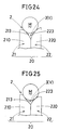
- Fig. 24 is an essential front view showing a different embodiment of the invention.
- Fig. 25 is an essential front view showing a different embodiment of the invention.
- Fig. 26 is an essential schematic plan view showing a different embodiment of the invention.
- Fig. 27 is an essential schematic side view of the above embodiment.
- Fig. 28 is an essential side view showing a different embodiment of the invention.
- Fig. 29 is an essential schematic bottom view showing a different embodiment of the invention.
- Fig. 30 is an essential schematic side view of the above embodiment.
- Fig. 31 is a schematic perspective view showing a further different embodiment of the invention.
- Fig. 32 is an essential schematic sectional view of the above embodiment of the invention.
- Fig. 33 is an essential front view of the above embodiment of the invention.
- Fig. 34 is an essential front view of the above embodiment of the invention.
- Fig. 35 is an essential explanatory diagram of the above embodiment of the invention.
- Fig. 36 is a general front view of the above embodiment of the invention.
- Fig. 1 shows an embodiment of the invention.
- the surface inspection apparatus of spherical matter such as steel balls of the invention is an apparatus usable in inspection of the surface of spherical matter M composed of steel ball, other metal ball, ceramic ball, spherical stone, plastic ball, or other material, and comprises an inspection unit 1 having electromagnetic sensors such as photo sensors, and a holder 2 for mounting the spherical matter M.
- composition of each component is sequentially described below.
- the inspection unit 1 is capable of inspecting defects on the surface of spherical matter M mounted on the holder 2 by means of a proper number of electromagnetic sensors.
- the inspection unit 1 possesses plural photo sensors 10 ....
- the sensors 10 ... emit light to the object of inspection, and receive the reflected light to inspect the surface.
- a projector 11 and a receiver 12 may be formed (integrated) into a unit, or the projector 11 and receiver 12 may be installed separately (Fig. 3).
- the photo sensors 10 are disposed radially, but it is also possible to execute in other configuration.
- the photo sensors 10 may be also realized by those designed to inspect the surface by using electromagnetic waves other than ordinary visible rays of light.
- the number of sensors 10 ... to be disposed is not limited to the shown example, but it is possible to execute if more than or smaller than the shown number
- the individual sensors 10 may be formed in a small size as far as possible and the interval of the adjacent sensors 10, 10 may be be set small in order to increase the number of sensors 10 ... to be installed, so that the number of positions and the scope to be inspected once by the inspection unit 1 may increase, which contributes to efficiency and effect of inspection.
- the holder 2 possesses a rotatable support 20, and an auxiliary support 23 capable of supporting the spherical matter M together with the support 20. Each constituent member of the holder 2 is explained sequentially below.
- the support 20 possesses a disk-shaped rotary part 200, a rotary shaft 201, and a bearing 202.
- the disk-shaped rotary part 200 possesses a receiving groove 3 formed annularly along the circumference. This receiving groove 3 is at a position withdrawn from the surface of the rotary part 200 as shown in Fig. 1.
- the receiving groove 3 receives the vicinity of the spherical matter M (Fig. 12).
- the receiving groove 3 is shown in withdrawn position in a form of V in sectional view, but such shape is not limited, and the receiving groove 3 may be formed in other shapes, such as U-form in sectional view.
- the inclination angle of the both inner walls may be set larger or smaller than shown in the diagram, and the depth may be also different from the shown size.
- the receiving groove 3 may be formed in a proper size depending on the size of the spherical matter M.
- the rotary shaft 200 has one end fixed in the middle of the rear end surface of the rotary part 200 (in Fig. 1, the right side of the rotary part 200 is the front end, and the left side is the rear end).
- the rotary shaft 200 is designed to rotate the rotary pat 200 by the torque obtained from the torque feed means such as motor.
- Such torque feed means is connected directly to the rotary shaft 201, or the torque may be obtained through gear or pulley and belt.
- the bearing 202 is to rotatably support the rotary shaft 201.
- the constitution for supporting the bearing 202 is omitted in order to avoid complication of the drawing.
- a projecting shaft 203 as an extension of the rotary shaft 201 is also provided in the middle of the front end surface of the rotary part 200, and a bearing 204 for freely fitting the projecting shaft 203 is provided, so that it may be effective for supporting the rotary part 200 from both sides.
- the auxiliary support 23 is a tubular body extending in the horizontal direction as shown in Fig. 3, and the rear end is fixed to the device, while the front end (the left side in Fig. 3 is the front end, and the right side is the rear end) contacts with the lateral surface of the spherical matter M, thereby preventing the spherical matter M from dropping out of the receiving groove 3.
- the spherical matter M is held at specific position by the support 20 and auxiliary support 23.
- the auxiliary support 23 has a rotating body 230 such as rubber roller at its front end as shown in Fig. 5, and this rotating body 230 obtains a torque from a motor or the like (different from the one for feeding torque to the rotary shaft 211, not shown) through transmission means of worm gear 234 or the like, and rotates the spherical matter M in a direction different from the torque given by the support 1 to the spherical matter M, which is also effective.
- a rotating body 230 such as rubber roller at its front end as shown in Fig. 5
- this rotating body 230 obtains a torque from a motor or the like (different from the one for feeding torque to the rotary shaft 211, not shown) through transmission means of worm gear 234 or the like, and rotates the spherical matter M in a direction different from the torque given by the support 1 to the spherical matter M, which is also effective.
- the constitution for rotating the rotating body 230 is not limited to the one shown in Fig. 5, and it may be realized by the one for rotating by using pulley or pulley belt, or the one for obtaining torque by other method.
- the rotating body 230 itself, it is not limited to the rubber roller, but other material or member may be used.
- the holder 2 is composed of the support 20 and auxiliary support 23, but as shown in Fig. 6, the holder 2 may be composed of a rotatable first support 21, a second support 22 rotatably independently of the rotation of the first support 21-, and an auxiliary support 23.
- the support 2 consists of, in the embodiment shown in Fig. 6, the first support 21 for composing the left part and the second support 22 for composing the right part, and the first support 21 and second support 22 are formed to rotate independently. Therefore, the support 2 in the foregoing (for example shown in Fig. 1) embodiment may be regarded to be a combined form of the first support 21 and the first support 21 to rotate in unison.
- the first support 21 and second support 22 are supposed to have a nearly same diameter of rotation, but the invention may be realized if the diameters of the first support 21 and second support 22 re different as far as capable of supporting the spherical matter and feeding rotary force to the spherical matter M.
- the first support 21 possesses a rotary part 210, a rotary shaft 211 and a bearing 212.
- the rotary part 210 is formed in a disk shape, and a tapered abutting surface 213 is formed on the circumference. In the center of the back side 214 of the rotary part 210, one end of the rotary shaft 211 is fixed.
- the rotary shaft 211 is rotate the rotary part 210 by the torque obtained from torque feed means such as motor (not shown).
- the bearing 212 rotatably supports the rotary shaft 211 (the support means of the bearing 212 itself is not shown in order to avoid complication of drawing).
- the rotary pat 220 is formed in a disk shape, and a tapered abutting surface 223 is formed on the circumference. In the center of the back side 224 of the rotary part 220, one end of the rotary shaft 221 is fixed.
- the rotary shaft 221 is rotate the rotary part 220 by the torque obtained from torque feed means such as motor (not shown).
- the bearing 222 rotatably supports the rotary shaft 221 (the support means of the bearing 222 itself is not shown in order to avoid complication of drawing).
- the first support 21 and second support 22 are disposed so that the both rotary shafts 211, 212 may be positioned on a same straight line, and that the disk surfaces of the two rotary parts 210, 220 may confront each other.
- the both abutting surfaces 213, 223 of the first support 21 and second support 22 form a bottom V in a V form in sectional view, and the spherical matter M is put on this bottom V.
- the slope angle of the abutting surfaces 213, 223 for forming the bottom B may be changed properly depending on the size of the spherical matter M.
- the interval W between the two rotary parts 210, 220 may be changed properly depending on the size of the spherical matter M to be mounted.
- the abutting surfaces 213, 223 are not limited to taper shape (conical form or truncated conical form), but may be formed in different shapes. Therefore, the bottom V formed by the abutting surfaces 213, 223 is not limited to a V section, but may be formed in other shape depending on the shape of other abutting surfaces 213, 223.
- the bottom V in V section formed by the abutting surfaces 213, 223 corresponds to the receiving groove 3 in the foregoing embodiment (for example as shown in Fig. 1). Therefore, other embodiments of the bottom V are explained together with other embodiments of the shape of the receiving groove 3 in Fig. 1.
- the spherical matter M is securely supported at three points by the abutting surfaces 213, 223 and the auxiliary support 23.
- the respective rotary parts 210, 220 of the first support 21 and second support 22 rotate at different speeds, and the rotating direction of the spherical matter M may be changed.
- the change of the rotating direction of the spherical matter M is adjusted, and the most efficient change of rotating direction of the spherical matter M may be set.
- the drive systems (motors, etc.) of the first support 21 and second support 22 may be composed separately, so that the constitution may be simplified. Otherwise, using one (common) motor for feeding torque, plural gears with different gear ratios, or plural pulleys and belts with different diameters may be employed in the driving force transmission system, that is, by constituting them through the motor and individual rotary shafts 211, 221, the rotating speeds of the first support 21 and second support 22 may be varied (not shown).
- the difference in rotating speed can be changed depending on necessity.
- the rotation is not limited to one revolution or more, but half rotation or quarter rotation or other rotation of small angle may be also included in the concept of rotation as far as the inspection is done sufficiently.
- the driving means of the first support 21 and second support 22 or the driving force transmitting means are further illustrated in other embodiments in Figs. 7, 8 and 9.
- Fig. 7 differs from the embodiment shown in Fig. 6, and the first support 21 and second support 22 are not in contact-free state. More specifically, a bearing 214 is formed in the center of the surface of the first support 21, and a projecting shaft 224 as an extension of the rotary shaft is formed in the center of the surface of the second support 22, and this projecting shaft 224 is rotatably incorporated in the bearing 214.
- the first support 21 may be partly responsible for support of the second support 22 without being blocked of its own rotation.
- FIG. 8 What is shown in Fig. 8 is characterized by free fitting of the first support 21 and second support 22 on one rotary shaft 240. More particularly, in the first support 21, the rotary part 210 and bearing 212 are integrally formed, while, in the second support 22, the rotary part 220 and bearing 222 are integrally formed.
- the supports 21, 22 are free to rotate on the shaft 240, and both first support 21 and second support 22 are composed so as to receive supply of torque directly from each other (the torque feed means is omitted to avoid complication of the drawing).
- FIG. 9 What is shown in Fig. 9 is a compound type of the embodiment shown in Fig. 6 or Fig. 7 and the embodiment shown in Fig. 8.
- the rotary pat 210 and bearing 212 are formed integrally, and are composed to be free to rotate on the shaft 240.
- the first support 21 rotates as torque is directly supplied from the other (the transmission means is omitted to avoid complication of drawing).
- the rotary part 220 and rotary shaft 221 are integrally formed, and other bearing 222 is provided.
- the rotary shaft 221 is united with the shaft 240 (one is the extension of the other), and it is designed to rotate the rotary part 220 by supply of torque from the other.
- an auxiliary bearing 231 is provided separately to stabilize rotation.
- FIG. 10 What is shown in Fig. 10 is similar to the embodiment in Fig. 1 or Fig. 2, in which the internal sectional shape of the receiving groove of the support 20 for supporting the spherical matter M is shaped in an arc form or in a form along the spherical matter.
- the support 20 is composed of the first support 21 and second support 22, and the receiving groove 3 is supposed to be composed of the abutting surfaces 213, 223 possessed by the both supports 21, 22 (therefore, the receiving groove 3 corresponds to the bottom V; see Fig. 12).
- the first support 21 and second support 22 are formed in one body.
- the first support 21 and second support 22 are disposed at a proper interval.
- the sectional shape along the spherical matter M is respectively formed on an arc.
- Numeral 30 is a spacer in disk form or shaft form for maintaining the interval between the first support 21 and second support 22.
- the spacer 30 is formed integrally with the first support 21 and second support 22 in the case of type A.
- the spacer 30 may be executed if independent from both the first support 21 and second support 22 (free from effects of rotation of both), or if attached to either the first support 21 or the second support 22, or if rotating together with the first support 21 and second support 22.
- the abutting surfaces 213, 223 may be merely formed in an arc, not formed completely along the spherical matter M.
- the embodiment shown in Fig. 14 is nearly same as the one shown in Fig. 13 in constitution except for the abutting surfaces 213, 223.
- the spacer 30 is broader in width (the lateral width in Fig. 14) than the one shown in Fig. 13, but the dimensions such as the width of the spacer 30 may be changed as required.
- type B incidentally, when the constitution shown in Fig. 13 or Fig. 14 is applied, it is also possible to keep an interval of the first support 21 and second support 22 without using the spacer 30. This is also possible in other embodiments described below.
- Fig. 15 is a compound type of the embodiment shown in Fig. 13 and the embodiment shown in Fig. 14. That is, one of the abutting surfaces 213, 223 is formed completely along the spherical matter M, but the other is formed in an arc (in sectional view) not completely formed along the spherical matter M.
- the invention may be also realized if the rotary parts 210, 220 of the first support 21 and second support 22 are not formed symmetrically.
- the abutting surfaces 213, 223 have a convex curvature on the outside.
- This embodiment same as shown in Fig. 16, does not have the spacer 30 and wide gap between the first support 21 and second support 22, but aside from this, it is also possible to realize a constitution having a proper gap between the first support 21 and second support 22 by using spacer 30 or other means mentioned above.
- the first support 21 and second support 22 are a combination of different shapes.
- Fig. 18 presents a combination of Fig. 12 and Fig. 17, but other different shapes may be also combined.
- first support 21 and second support 22 may differ in the diameter of rotation (or maximum outside diameter in standing still) or thickness (the lateral direction in Fig. 12 to Fig. 18).
- Fig. 19 similar to the embodiment in Fig. 12, the outside diameter and width of the first support 21 and second support 22 are different.
- the slope angles of the abutting surfaces 213, 223 differ in the first support 21 and second support 22.
- first support 21 and second support 22 differ in the diameter of rotation (or maximum outside diameter in standing still) and thickness (lateral width in drawing).
- first support 21 and second support 22 differ in the diameter of rotation (or maximum outside diameter in standing still) and thickness (lateral width in drawing).
- first support 21 and second support 22 differ in the diameter of rotation (or maximum outside diameter in standing still) and thickness (lateral width in drawing).
- the first support 21 and second support 22 differ in the diameter of rotation (or maximum outside diameter in standing still).
- the thickness (lateral width in drawing) of the first support 21 and second support 22 is nearly equal, but it is realized if the thickness is also different.
- first support 21 and second support 22 differ in the diameter of rotation (or maximum outside diameter in standing still) and thickness (lateral width in drawing).
- the first support 21 and second support 22 differ in the diameter of rotation (or maximum outside diameter in standing still).
- the thickness (lateral width in drawing) of the first support 21 and second support 22 is nearly equal, but it is realized if the thickness is also different.
- Fig. 12 to Fig. 25 can be realized whether in type A or in type B.
- a feed unit 4 for accommodating the spherical matters M to be inspected is provided, and a guide 40 for sending the spherical matters M sequentially from the bottom of the feed unit 4 to the holder 2 is provided in the feed unit 4.
- the inspection unit 1 projects light from the projector 11 to the surface of the spherical matter M sent to the holder 2 automatically from the feed unit 4 by the guide 40, and receives the reflected light in the receiver 12. The result is sent to the photo sensor array 13.
- the auxiliary support 23 has its rear end fixed to the other end, and when the inspection is over, the front end is lifted upward, and the spherical matter M is released and dropped into the sorting unit 5.
- the sorting unit 5 detects by the photo sensor array 13, and sorts the spherical matter M on the basis of the data of approval or rejection sent to the integrated circuit 14.
- the sorting unit 5 is realized by an existing device.
- the sorting unit 5 constitutes a branched passage as shown in Fig. 3, and a rejected spherical matter M as a result of inspection is sent into one passage 51, and an approved spherical matter M is sent into the other passage 52.
- the sorting unit 5 sorts out the individual spherical matters M according to approval or rejected as judged by the inspection unit 1
- the constituent members such as sensor 10 and holder 2 are placed in liquid E for the purpose of inspection, but it is also possible to inspect by placing in gas or in vacuum.
- the liquid E is not limited in kind, and inspection may be done in oil, water-soluble rust preventive, or other liquid.
- auxiliary support 23 has a rotating body 230 to apply torque independently from the other support to the spherical matter M
- first support 21 and second support 22 may be constituted as shown in Fig. 12 through Fig. 25.
- the auxiliary support 23 may be also constituted, for example, as shown in Fig. 26 and Fig. 27, to have the rotating body 230 in the same shape as the support 20 (or the first support 21 and second support 22). Therefore, the rotating body 230 may be similar in shape or constitution to the support 20 shown in Fig. 1 and Fig. 2 or Fig. 10 through Fig. 25, or the first support 21 and second support 22 in Fig. 6 through Fig. 9 or Fig. 12 through Fig. 25.
- the rotating body 230 is not limited to the arrangement in the same direction as the support 20 or first support 21 and second support 22, and while having the same or similar shape as the support 20 or other, it may also possess a rotary shaft at right angle to the rotary shaft of the support 20 or the like, same as the embodiment shown in Fig. 5.
- the rotating body 230 may rotate independently by receiving supply of torque from outside (not shown) same as in the embodiment shown in Fig. 5, but without having the own rotating mechanism, it may be designed to be rotated along with rotation of the spherical matter M to support the spherical matter M auxiliarily.
- the structure for supporting the rotating body 230 is not limited to the structure shown in the drawing, but a similar structure as in the support 20 or first support 21 and second support 22 may be employed.
- the projector 11 and receiver 12 may be held individually, but the projector 11 and receiver 12 may be held together by using a holder 100 of wedge section as shown, for example, in Fig. 28.
- the photo sensors 10 ... of the inspection unit may have a multiple-to-one correspondence. More specifically, for instance as shown in Fig. 29, plural receivers 12 may be disposed around one projector 11. In Fig. 29, incidentally, optical fibers of four receivers 12 are disposed around the optical fiber of the projector 11, but the quantity is not particularly defined, and the embodiment is realized whether the number of optical fibers of the receivers 12 is more than four or not.
- the photo sensors 10 ... shown in Fig. 29 are employed, as shown in Fig. 30, the light emitted by the projector 11 is received individually by the receivers 12.
- the arrangement of the photo sensors 10 ... is not limited to a sector layout, and individual photo sensors 10 ... may be differently configured.
- the photo sensor 10 shown in Fig. 29 and Fig. 30 only one photo sensor 10 is shown in the diagram, but it is not limitative, and a plurality may be disposed. In such a case, too, the configuration of the sensors 10 ... is free, and they may be disposed at arbitrary positions as required.
- ball bearings are used as bearings 202, 204 and bearings 212, 222, 231, but bearings of other known construction may be also employed (not shown).
- the apparatus comprises a feed unit 4 for feeding spherical matter M such as steel balls, a transfer unit 26 for transferring the spherical matter M supplied from the feed unit 4 for a specific distance, an inspection unit 1 for inspecting the surface of the spherical matter M on the transfer unit 26 by using electromagnetic waves such as rays of light, and a sorting unit 5 for sorting the spherical matter M sent from the transfer unit 26 depending on the result of inspection by the inspection unit 1.
- the individual constituent elements are sequentially described below.
- the feed unit 4 is formed as a hopper for accommodating plural spherical matters M, and is designed to drop the spherical matters M one by one from its bottom to one end of the transfer unit 26.
- a guide tube 40 is projecting from the bottom of the feed unit 4 downward to the transfer unit 2 side, and the spherical matter M is guided upward to the transfer unit 26 through the guide tube 40.
- the transfer unit 26 is formed by extending a first support 21 of nearly columnar form to form a transfer route of spherical matter M and a second support 22 having at least a nearly same longitudinal width as the first support 21, almost horizontally from the feed unit 4 side to the sorting unit 5 side.
- the first support 21 and second support 22 are formed in a columnar form. Being thus formed, the first support 21 and second support 22 compose a transfer route of the spherical matter M to be mentioned later.
- the transfer route (the narrow gap 350 mentioned later) formed by these members has a sufficient length for keeping a necessary transfer time for completion of inspection of the spherical matter M by the inspection unit 1 as described below.
- a guide groove 300 extending spirally from the end of the feed unit 4 side to the end of the sorting unit 5 side is formed on the outer circumference. That is, a spiral groove such as the worm of worm gear is formed.
- the first support 21 rotates about the symmetrical axis X (virtual line) of the column formed by itself (Fig. 32). Rotating means such as motor for transmitting its torque to the first support 21 is omitted in order to avoid complication of the drawing.
- the guide groove 300 transfers and guides the spherical matter M from the end of the feed unit 4 side to the end of the sorting unit 5 side by the rotation of the first support 21, and sequentially changes the rotating direction of the spherical matter itself in the process of transfer.
- plural transfer rest positions 301 ... of which lead angle is almost zero are formed.
- the spiral of this guide groove 300 may be either clockwise or counterclockwise, or may be twin spiral (double spiral), and the shown example is not limitative. However, considering the relation with the rotating direction of the first support 21 and rotating direction and configuration of the second support 22, it must be set so that the spherical matter M may be sent from the feed unit 4 to the sorting unit 5.
- the lead angle is uniform in other parts than the transfer rest positions 301 ..., but the embodiment is realized also if the lead angle differs depending on the position of the spiral guide groove 300.
- the interval of adjacent guide grooves 300, the groove width a of the guide groove 300 shown in Fig. 35 (about 80 degrees in the diagram), and the angle b and depth c of cut may be set properly according to the size of the spherical matter M to be transferred.
- the outside diameter of the first support 21 may be set properly depending on the size of the spherical matter M to be transferred.
- the second support 22 is, as shown in Fig. 32, nearly of columnar form same as the first support 21, and is disposed almost parallel adjacently to the first support 21, thereby forming a narrow gap 350 against the first support 21.
- This narrow gap 350 is to prevent the spherical matter M mounted upward from dropping down. Therefore, this narrow gap 350 may be also set according to the size of the spherical matter M to be inspected.
- the second support is also designed to rotate, same as the first support 21, about the own symmetric axis X.
- the second support 22 is always rotating, but if not necessary, such rotating structure is not required.
- the shape of the second support 22 is not limited to the columnar form, and it may be formed, for example, as a wall along the first support 21, or in other form than columnar form.
- the second support 22 may be formed in a columnar form having a guide groove with a reverse lead angle (not shown).
- the spherical matter M By mounting the spherical matter M in the narrow gap 350 as transfer route, the spherical matter in the midst of transfer is supported by making use of the force of the spherical matter M in a direction of dropping into the narrow gap 350.
- the first support 21 rotates in the Y-direction and the second support 22 rotates in the Z-direction. Receiving such torque, the spherical matter M rotates, and advances through the narrow gap 305 toward the sorting unit 5 side.
- This forward move of the spherical matter M is effected by the guidance of the guide groove 300. More specifically, a part of the spherical matter M gets into the guide groove 300, and the spherical matter M advances along the guide groove 300 sequentially dislocated by the rotation of the first support 21. While moving, the spherical matter M gets into the section of transfer rest position 301 of the guide groove 300 and is defined by the transfer rest position 301, and in this period, stopping the forward move, the spherical matter M is standing still (in rest state).
- the inspection unit 1 possesses plural electromagnetic sensors 10 ... such as photo sensors, and the individual sensors 10 ... are disposed along the longitudinal direction of the first support 21 near the first support 21.
- the projector 11 and receiver 12 are composed as a pair.
- the projector 11 composed of optical fiber and the receiver 12 are individually provided, but they may be also put in a same unit.
- the individual sensors 10 are designed to judge approval or rejection of spherical matter M depending on the quantity of light reflected from the spherical matter M by projecting light.
- the sensors 10 ... are disposed at proper mutual intervals, project light to the surface of the spherical matter M standing still at the individual transfer rest positions 301 ... of the guide groove 300, and receive the reflected light to inspect the surface of the spherical matter M, thereby detecting flaw, distortion or other defect.
- the spherical matter M is changed in direction sequentially and uniformly by the spiral guide groove 300, thereby avoiding the inspection on the same specific circumference only by all sensors 10 (lowering the probability of such bias or duplication of inspection positions), so that one spherical matter M can be inspected from different direction and at multiple angles by the sensors 10.
- Numeral 6 in Fig. 31 shows a position detection device, of which data is sent to an integrated circuit 60 to control the rotation of the first support 21 or second support 22 if necessary to be tuned between the sensors 10 ... of the inspection unit 3 and the transferred spherical matter M. For example, if necessary, when the spherical matter M gets into the transfer rest position 301 where sensors 10 ... are located, the rotation of the first support 21 is stopped, or reduced in speed.
- the sorting unit 5 composes a branched passage also in this embodiment as shown in Fig. 31, and the spherical matter M rejected as a result of inspection is sent into one branched passage 51, and the approved spherical matter M is sent into the other passage 52. In this way, the sorting unit 5 judges individual spherical matters M according to the inspection result obtained from the inspection unit 1, and sorts out.
- the passages 51, 52 are selected by a lid which opens one passage and closes the other depending on the approval or rejection of the spherical matter M transferred by placing it at the branching position, or they may be also selected by other known means.
- the spherical matter M is sent from the feed unit 5 to the transfer unit 26 sequentially, and multiple spherical matters M can be inspected automatically.
- plural spherical matters M are mounted in a row on the transfer unit 26, and therefore means for specifying a defective spherical matter M is needed.
- a device having twelve sensors 10 ... may be used, in which twelve data receivers (not shown) corresponding one to one to the individual sensors 10 ... are provided in the inspection unit 1.
- the information is sent to the data receivers of the sixth and subsequent sensors 10 ..., so that it is known in which sensor 10 the defective spherical matter M is now passing.
- the defective spherical matter M has passed the final sensor 10, it is treated as rejection in the sorting unit 4 by the data of the data receiver of the final sensor 10.
- the number of revolutions required for the first support 21 from that sensor 10 position to reach the final sensor 10 position or the front end of the first support 21 may be preliminarily input in the control means so as to control accordingly.
- a display panel 130 is provided near a device main body 100 comprising feed unit 4, transfer unit 26, inspection unit 1 and sorting unit 5, and lamps 131 ... corresponding to individual sensors 10 ... are incorporated in the display panel 130.
- the lamp 131 corresponding to this sensor 10 lights up, and as the spherical matter m passes sequentially, the lamps 131 ... corresponding to the sensors 10 ... light up successively, so that the defective spherical matter M can be easily recognized from outside.
- the device main body 100 comprising feed unit 4, transfer unit 26, inspection unit 1 and sorting unit 5 is usually placed in the atmosphere (air), but it may be also placed in other ambient conditions. For example, it may be used in other gas than air, in vacuum or even in liquid.
- liquid If used in liquid, the kind of liquid is not specified, including oil, water-soluble rust preventive, and other liquids.
- the direction of the spherical matter may be automatically changed relatively to the sensor, and the surface of a great number of spherical matters can be inspected efficiently and precisely.
- the third invention plural positions on the surface of one spherical matter can be securely inspected, and defects can be detected thoroughly, and the qualification as product can be sorted at high precision.
- the fifth invention by the preliminary move in the preliminary section of the transfer unit, plural positions of the surface of spherical matter can be securely inspected, and defects can be inspected thoroughly, so that the qualification as product can be sorted at high precision.
Landscapes
- Physics & Mathematics (AREA)
- General Physics & Mathematics (AREA)
- Health & Medical Sciences (AREA)
- Life Sciences & Earth Sciences (AREA)
- Chemical & Material Sciences (AREA)
- Analytical Chemistry (AREA)
- Biochemistry (AREA)
- General Health & Medical Sciences (AREA)
- Immunology (AREA)
- Pathology (AREA)
- Investigating Materials By The Use Of Optical Means Adapted For Particular Applications (AREA)
Abstract
An apparatus for inspecting the surface of a steel ball and other spherical object enables defects to be detected on the surface of a spherical object placed on a holder 2 by means of an inspection unit 1 comprising a proper number of electromagnetic sensors. The holder 2 possesses a rotatable support 20 and an auxiliary support 23 for supporting the spherical object together with the support 20. The support 20 possesses a receiving groove 3 formed annularly along the rotating spherical peripheral surface, and this receiving groove 3 can accommodate the bottom of the spherical object, and by the rotation of the support 20, the spherical object can be rolled within the receiving groove 3 so that the orientation of the spherical object can be changed, thereby automatically changing the inspection position of the spherical object. As a result, the surface inspection precision of steel balls or other spherical objects can be enhanced, and product qualification can be determined automatically and efficiently.
Description
- The invention relates to a surface inspection apparatus of spherical matter such as steel balls, other metal balls, ceramic balls, spherical stones, plastic balls and the like.
- Hitherto, for surface flaw detection or roundness inspection of spherical matter such as steel balls, generally, light was emitted to the surface of the spherical matter, and the reflected light was detected by a photo sensor.
- In such detection, there has been a demand for detection of plural positions on the surface of spherical matter to enhance the precision of inspection.
- To meet such demand, it has been possible to inspect plural positions by one inspection job by using multiple sensors and disposing sensors at different positions on the spherical matter.
- If, however, desired to inspect each position on the surface of the spherical matter in a wide range by using multiple sensors, sensors cannot be disposed in the bottom of the spherical matter, for example, because it is supported on a holder or a table, which gives rise to necessity of inspecting again by turning upside down after inspecting the upper hemisphere of the spherical matter. If such job is done manually each time, it is impossible to inspect a large quantity of spherical samples efficiently. It is hence a primary object of the invention to solve such problems.
- A surface inspection apparatus of spherical matter according to a first invention comprises an
inspection unit 1 possessing electromagnetic sensors such as photo sensors, and aholder 2 for mounting steel balls or other spherical matter, and is constituted as follows. - The
inspection unit 1 detects surface defects of spherical matter put on theholder 2 by a proper number of electromagnetic sensors. Theholder 2 possesses arotatable support 20 and anauxiliary support 23 for supporting the spherical matter together with thesupport 20. Thesupport 20 possesses areceiving groove 3 formed in an annular form along its rotating peripheral surface, and this receivinggroove 3 can accommodate the vicinity of the bottom of the spherical matter, and the spherical matter is rolled within thereceiving groove 3 by the rotation of thesupport 20, so that the direction of the spherical matter can be changed. Theauxiliary support 23 is formed separately from thesupport 20, and disposed near thesupport 20, and is designed to support the portion of the spherical matter exposed from thereceiving groove 3, and holding the spherical matter at specific position. - In a surface inspection apparatus of spherical matter in a second invention, which is similar to the first invention, the
auxiliary support 23 possesses a rotatingbody 230 in the position contacting with the spherical matter. This rotatingbody 230 can rotate the spherical body in a different direction from the rotating direction of thesupport 20. - Furthermore, a surface inspection apparatus of spherical matter in a third invention comprises an
inspection unit 1 possessing electromagnetic sensors such as photo sensors, and aholder 2 for mounting steel balls or other spherical matter, and is constituted as follows. - That is, the
inspection unit 1 detects surface defects of spherical matter put on theholder 2 by a proper number of electromagnetic sensors. Theholder 2 possesses a rotatablefirst support 21, a rotatablesecond support 22, and anauxiliary support 23 for supporting the spherical matter together with thefirst support 21 andsecond support 22. Thefirst support 21 andsecond support 22 can rotate at mutually different rotating speeds. - In a surface inspection apparatus of spherical matter in a fourth invention, which is similar to the third embodiment, the
auxiliary support 23 possesses a rotatingbody 230 at a position contacting with the spherical matter, and the rotatingbody 230 provides the spherical matter with a torque in a proper direction. - A surface inspection apparatus of spherical matter in a fifth invention comprises a
feed unit 4 for feeding spherical matter such as steel balls, atransfer unit 26 for transferring the spherical matter supplied from thefeed unit 4 for a specific distance, aninspection unit 1 for inspecting the surface of the spherical matter on the transfer unit 24 by using electromagnetic wave such as beam of light, and asorting unit 5 for sorting the spherical matter sent from thetransfer unit 26 depending on the result of inspection by theinspection unit 1. Thetransfer unit 26 has afirst support 21 of nearly columnar shape forming the a transfer route for spherical matter, and asecond support 22 possessing a longitudinal width at least nearly same as thefirst support 21, formed as being extended from thefeed unit 4 side to thesorting unit 5 side. Thefirst support 21 rotates about the symmetrical axis of its own column, and aguide groove 300 extending spirally is formed on its circumference from the end part of thefeed unit 4 side to the end part of thesorting unit 5 side. The guide groove 300 transfers and guides the spherical matter from the end part of thefeed unit 4 side to the end part of thesorting unit 5 side, and sequentially varies the rotating direction of the spherical matter itself in the midst of transfer. In theguide groove 300, pluraltransfer rest positions 301 ... at lead angle of nearly zero are formed. As thesecond support 22 is disposed nearly parallel, adjacently to thefirst support 21, anarrow gap 350 is formed against thefirst support 21, and by mounting the spherical matter using thenarrow gap 350 as transfer route, the spherical matter is supported in the process of transfer by making use of the force of the spherical matter M falling into thenarrow gap 350. Theinspection unit 1 possesses pluralelectromagnetic sensors 10 ... such as photo sensors, and theindividual sensors 10... are disposed near thefirst support 21 along the longitudinal direction of thefirst support 21. Thesensors 10 ... are positioned at proper mutual intervals, and are designed to inspect the surface of the spherical matter staying in theindividual rest positions 301 ... of theguide groove 300. Thesorting unit 4 sorts by judging approval or rejection depending on the result of inspection obtained in eachinspection unit 1 for every spherical matter. - In the apparatus of the first invention employing the above means, the spherical matter contained in the
receiving groove 3 of thesupport 20 is rolled within the receivinggroove 3 by the rotation of thesupport 20, and the direction of the spherical matter is changed, so that the inspecting position of the spherical matter can be changed automatically. - In the apparatus of the second invention, since the spherical matter can be rotated in a different direction from the rolling direction of the spherical matter by the
support 20, all positions can be inspected uniformly without deviating the inspecting positions of the spherical matter, regardless of the quantity and location of the electromagnetic sensors of theinspection unit 1. - In the apparatus of the third invention, the
first support 21 andsecond support 22 for composing theholder 2 to support the spherical matter can be rotated at mutually different rotating speeds, and therefore the mounted spherical matter can change the rotating direction in multiple directions, not limited to one direction only. Therefore, the surface of the spherical matter can be inspected uniformly at multiple angles. - In the apparatus of the fourth invention, since the
rotating body 230 having theauxiliary support 23 can provide the spherical matter with a torque in the third embodiment, it is possible to convert the direction of the inspecting position of the spherical matter more finely, in addition to supply of torque to the spherical matter by thefirst support 21 andsecond support 22. - In the apparatus of the fifth invention, the
guide groove 300 extending almost spirally is formed in thefirst support 21 of thetransfer unit 26 interposed between thefeed unit 4 and sortingunit 5, and therefore the spherical matter supported by thefirst support 21 andsecond support 22 is guided by theguide groove 300 contacting therewith by the rotating of thefirst support 21, and is transferred from thefeed unit 4 side to thesorting unit 5 side, and is rotated sequentially in different directions. In theguide groove 300, thesensor 10 is disposed nearby and pluraltransfer rest positions 301 ... nearly at lead angle of zero are formed, and the spherical matter standing still can be inspected at individualtransfer rest positions 301 ..., so as to be inspected securely at the sensor position. Together with this, as mentioned above, as being guided by thespiral guide groove 300, the spherical matter is sequentially changed in the rotting direction while passing through individualtransfer rest positions 301, so that different positions of the spherical matter can be securely inspected by thesensors 10, thereby notably enhancing the precision inspection of each spherical matter. - The present invention further provides a surface inspection apparatus for inspecting a surface of a spherical object, comprising an inspection unit having electromagnetic sensors such as photo sensors, a proper number of sensors for detecting surface defects of the spherical object being preferably provided, and a holder for mounting a steel ball or other spherical object, wherein the holder has a rotatable support and an auxiliary support for together supporting a spherical object, the rotatable support has an annular receiving groove formed along its peripheral surface, for accommodating the bottom region of a spherical object, the spherical object being rollable within the receiving groove by the rotation of the rotatable support, so that the orientation of the spherical object can be changed, and the auxiliary support is formed separately from the rotatable support, and disposed near the rotatable support, and is designed to support an exposed portion of a spherical object received in the receiving groove and to hold the spherical object at a specific position.
- The present invention also provides apparatus for inspecting a spherical object, comprising an inspection unit having electromagnetic sensors such as photo sensors, a proper number of sensors for detecting surface defects of the spherical object being preferably provided, and a holder for mounting a steel ball or other spherical object, wherein:
the holder has a rotatable first support, a rotatable second support, and an auxiliary support for supporting a spherical object together with the first support and second support, and means for rotating the first support and second support at mutually different rotating speeds. - Fig. 1 is a partially cut-away front view showing an embodiment of the invention.
- Fig. 2 is a partially cut-away front view showing other embodiment of the invention.
- Fig. 3 shows general schematic side vies of the embodiments of the invention.
- Fig. 4 is an essential magnified view showing a different embodiment of the invention.
- Fig. 5 is a partially cut-away essential magnified view showing a different embodiment.
- Fig. 6 is a partially cut-away front view showing an embodiment of the invention.
- Fig. 7 is a partially cut-away front view showing a different embodiment of the invention.
- Fig. 8 is a partially cut-away front view showing a different embodiment of the invention.
- Fig. 9 is a partially cut-away front view showing a different embodiment of the invention.
- Fig. 10 is an essential front view showing a different embodiment of the invention.
- Fig. 11 is an essential front view showing a different embodiment of the invention.
- Fig. 12 is an essential front view of the above embodiment of the invention.
- Fig. 13 is an essential front view showing a different embodiment of the invention.
- Fig. 14 is an essential front view showing a different embodiment of the invention.
- Fig. 15 is an essential front view showing a different embodiment of the invention.
- Fig. 16 is an essential front view showing a different embodiment of the invention.
- Fig. 17 is an essential front view showing a different embodiment of the invention.
- Fig. 18 is an essential front view showing a different embodiment of the invention.
- Fig. 19 is an essential front view showing a different embodiment of the invention.
- Fig. 20 is an essential front view showing a different embodiment of the invention.
- Fig. 21 is an essential front view showing a different embodiment of the invention.
- Fig. 22 is an essential front view showing a different embodiment of the invention.
- Fig. 23 is an essential front view showing a different embodiment of the invention.
- Fig. 24 is an essential front view showing a different embodiment of the invention.
- Fig. 25 is an essential front view showing a different embodiment of the invention.
- Fig. 26 is an essential schematic plan view showing a different embodiment of the invention.
- Fig. 27 is an essential schematic side view of the above embodiment.
- Fig. 28 is an essential side view showing a different embodiment of the invention.
- Fig. 29 is an essential schematic bottom view showing a different embodiment of the invention.
- Fig. 30 is an essential schematic side view of the above embodiment.
- Fig. 31 is a schematic perspective view showing a further different embodiment of the invention.
- Fig. 32 is an essential schematic sectional view of the above embodiment of the invention.
- Fig. 33 is an essential front view of the above embodiment of the invention.
- Fig. 34 is an essential front view of the above embodiment of the invention.
- Fig. 35 is an essential explanatory diagram of the above embodiment of the invention.
- Fig. 36 is a general front view of the above embodiment of the invention.
- Referring now to the drawings, some of the embodiments of the invention are described specifically below. Fig. 1 shows an embodiment of the invention.
- As shown in Fig. 1, the surface inspection apparatus of spherical matter such as steel balls of the invention is an apparatus usable in inspection of the surface of spherical matter M composed of steel ball, other metal ball, ceramic ball, spherical stone, plastic ball, or other material, and comprises an
inspection unit 1 having electromagnetic sensors such as photo sensors, and aholder 2 for mounting the spherical matter M. - The composition of each component is sequentially described below.
- The
inspection unit 1 is capable of inspecting defects on the surface of spherical matter M mounted on theholder 2 by means of a proper number of electromagnetic sensors. - More specifically, it is formed separately from the
holder 2 mentioned below, and is disposed above theholder 2. - The
inspection unit 1 possessesplural photo sensors 10 .... Thesensors 10 ... emit light to the object of inspection, and receive the reflected light to inspect the surface. - As
such photo sensor 10, aprojector 11 and areceiver 12 may be formed (integrated) into a unit, or theprojector 11 andreceiver 12 may be installed separately (Fig. 3). - In the embodiment shown in Fig. 1, the
photo sensors 10 are disposed radially, but it is also possible to execute in other configuration. - The
photo sensors 10 may be also realized by those designed to inspect the surface by using electromagnetic waves other than ordinary visible rays of light. - The number of
sensors 10 ... to be disposed is not limited to the shown example, but it is possible to execute if more than or smaller than the shown number - The
individual sensors 10 may be formed in a small size as far as possible and the interval of theadjacent sensors sensors 10 ... to be installed, so that the number of positions and the scope to be inspected once by theinspection unit 1 may increase, which contributes to efficiency and effect of inspection. - The
holder 2 possesses arotatable support 20, and anauxiliary support 23 capable of supporting the spherical matter M together with thesupport 20. Each constituent member of theholder 2 is explained sequentially below. Thesupport 20 possesses a disk-shapedrotary part 200, arotary shaft 201, and abearing 202. - The disk-shaped
rotary part 200 possesses a receivinggroove 3 formed annularly along the circumference. This receivinggroove 3 is at a position withdrawn from the surface of therotary part 200 as shown in Fig. 1. - The receiving
groove 3 receives the vicinity of the spherical matter M (Fig. 12). In Fig. 1, the receivinggroove 3 is shown in withdrawn position in a form of V in sectional view, but such shape is not limited, and the receivinggroove 3 may be formed in other shapes, such as U-form in sectional view. Or, when forming the receivinggroove 3 in an approximately V-form in sectional view, the inclination angle of the both inner walls may be set larger or smaller than shown in the diagram, and the depth may be also different from the shown size.The receivinggroove 3 may be formed in a proper size depending on the size of the spherical matter M. - Concerning the form of the
holder 2 and receivinggroove 3, other embodiments are described below. - In the above embodiment, the
rotary shaft 200 has one end fixed in the middle of the rear end surface of the rotary part 200 (in Fig. 1, the right side of therotary part 200 is the front end, and the left side is the rear end). Therotary shaft 200 is designed to rotate therotary pat 200 by the torque obtained from the torque feed means such as motor. - Such torque feed means is connected directly to the
rotary shaft 201, or the torque may be obtained through gear or pulley and belt. - The
bearing 202 is to rotatably support therotary shaft 201. In the drawing, the constitution for supporting thebearing 202 is omitted in order to avoid complication of the drawing. - Or, as shown in Fig. 2, a projecting
shaft 203 as an extension of therotary shaft 201 is also provided in the middle of the front end surface of therotary part 200, and abearing 204 for freely fitting the projectingshaft 203 is provided, so that it may be effective for supporting therotary part 200 from both sides. - The
auxiliary support 23 is a tubular body extending in the horizontal direction as shown in Fig. 3, and the rear end is fixed to the device, while the front end (the left side in Fig. 3 is the front end, and the right side is the rear end) contacts with the lateral surface of the spherical matter M, thereby preventing the spherical matter M from dropping out of the receivinggroove 3. Thus, the spherical matter M is held at specific position by thesupport 20 andauxiliary support 23. - By the rotation of the
support 20, the spherical matter M rolls within the receivinggroove 3, and its direction is changed relatively to theinspection unit 1. - When the front end of the
auxiliary support 23 is provided with abearing 231 as shown in Fig. 4, the rotation of the spherical matter M by thesupport 20 can be effected smoothly, and it is very effective. - Moreover, the
auxiliary support 23 has arotating body 230 such as rubber roller at its front end as shown in Fig. 5, and thisrotating body 230 obtains a torque from a motor or the like (different from the one for feeding torque to therotary shaft 211, not shown) through transmission means ofworm gear 234 or the like, and rotates the spherical matter M in a direction different from the torque given by thesupport 1 to the spherical matter M, which is also effective. - The constitution for rotating the
rotating body 230 is not limited to the one shown in Fig. 5, and it may be realized by the one for rotating by using pulley or pulley belt, or the one for obtaining torque by other method. - When employing the constitution of the gear or the like, it is not limited to the one in Fig. 5, but it may be realized by employing gears of other configuration or different quantity, or gears of other types.
- As for the
rotating body 230 itself, it is not limited to the rubber roller, but other material or member may be used. - In the above embodiment, the
holder 2 is composed of thesupport 20 andauxiliary support 23, but as shown in Fig. 6, theholder 2 may be composed of a rotatablefirst support 21, asecond support 22 rotatably independently of the rotation of the first support 21-, and anauxiliary support 23. - More specifically, the
support 2 consists of, in the embodiment shown in Fig. 6, thefirst support 21 for composing the left part and thesecond support 22 for composing the right part, and thefirst support 21 andsecond support 22 are formed to rotate independently. Therefore, thesupport 2 in the foregoing (for example shown in Fig. 1) embodiment may be regarded to be a combined form of thefirst support 21 and thefirst support 21 to rotate in unison. - In this embodiment, the
first support 21 andsecond support 22 are supposed to have a nearly same diameter of rotation, but the invention may be realized if the diameters of thefirst support 21 andsecond support 22 re different as far as capable of supporting the spherical matter and feeding rotary force to the spherical matter M. - These supports 21, 22, 23 support so that the spherical matter M may not drop out.
- Hereinafter the constituent members of the
holder 2 of the embodiment shown in Fig. 6 are explained. - The
first support 21 possesses arotary part 210, arotary shaft 211 and abearing 212. Therotary part 210 is formed in a disk shape, and a taperedabutting surface 213 is formed on the circumference. In the center of theback side 214 of therotary part 210, one end of therotary shaft 211 is fixed. Therotary shaft 211 is rotate therotary part 210 by the torque obtained from torque feed means such as motor (not shown). The bearing 212 rotatably supports the rotary shaft 211 (the support means of thebearing 212 itself is not shown in order to avoid complication of drawing). - The
second support 22, same as thefirst support 21, possesses arotary shaft 221 and abearing 222. Therotary pat 220 is formed in a disk shape, and a taperedabutting surface 223 is formed on the circumference. In the center of theback side 224 of therotary part 220, one end of therotary shaft 221 is fixed. Therotary shaft 221 is rotate therotary part 220 by the torque obtained from torque feed means such as motor (not shown). The bearing 222 rotatably supports the rotary shaft 221 (the support means of thebearing 222 itself is not shown in order to avoid complication of drawing). - As shown in Fig. 6, the
first support 21 andsecond support 22 are disposed so that the bothrotary shafts rotary parts surfaces first support 21 andsecond support 22 form a bottom V in a V form in sectional view, and the spherical matter M is put on this bottom V. The slope angle of the abuttingsurfaces rotary parts surfaces surfaces surfaces - Herein, the bottom V in V section formed by the abutting
surfaces groove 3 in the foregoing embodiment (for example as shown in Fig. 1). Therefore, other embodiments of the bottom V are explained together with other embodiments of the shape of the receivinggroove 3 in Fig. 1. - The spherical matter M is securely supported at three points by the abutting
surfaces auxiliary support 23. - In this constitution, the respective
rotary parts first support 21 andsecond support 22 rotate at different speeds, and the rotating direction of the spherical matter M may be changed. By adjusting the difference in rotating speed of therotary parts - When rotating the
first support 21 andsecond support 22 at different rotating speeds, as mentioned above, the drive systems (motors, etc.) of thefirst support 21 andsecond support 22 may be composed separately, so that the constitution may be simplified. Otherwise, using one (common) motor for feeding torque, plural gears with different gear ratios, or plural pulleys and belts with different diameters may be employed in the driving force transmission system, that is, by constituting them through the motor and individualrotary shafts first support 21 andsecond support 22 may be varied (not shown). - The difference in rotating speed can be changed depending on necessity. The rotation is not limited to one revolution or more, but half rotation or quarter rotation or other rotation of small angle may be also included in the concept of rotation as far as the inspection is done sufficiently.
- The driving means of the
first support 21 andsecond support 22 or the driving force transmitting means are further illustrated in other embodiments in Figs. 7, 8 and 9. - What is shown in Fig. 7 differs from the embodiment shown in Fig. 6, and the
first support 21 andsecond support 22 are not in contact-free state. More specifically, abearing 214 is formed in the center of the surface of thefirst support 21, and a projectingshaft 224 as an extension of the rotary shaft is formed in the center of the surface of thesecond support 22, and this projectingshaft 224 is rotatably incorporated in thebearing 214. By thus constituting, thefirst support 21 may be partly responsible for support of thesecond support 22 without being blocked of its own rotation. - What is shown in Fig. 8 is characterized by free fitting of the
first support 21 andsecond support 22 on onerotary shaft 240. More particularly, in thefirst support 21, therotary part 210 and bearing 212 are integrally formed, while, in thesecond support 22, therotary part 220 and bearing 222 are integrally formed. The supports 21, 22 are free to rotate on theshaft 240, and bothfirst support 21 andsecond support 22 are composed so as to receive supply of torque directly from each other (the torque feed means is omitted to avoid complication of the drawing). - What is shown in Fig. 9 is a compound type of the embodiment shown in Fig. 6 or Fig. 7 and the embodiment shown in Fig. 8.
- In detail, in the
first support 21, therotary pat 210 and bearing 212 are formed integrally, and are composed to be free to rotate on theshaft 240. Thefirst support 21 rotates as torque is directly supplied from the other (the transmission means is omitted to avoid complication of drawing). In thesecond support 22, on the other hand, therotary part 220 androtary shaft 221 are integrally formed, andother bearing 222 is provided. Therotary shaft 221 is united with the shaft 240 (one is the extension of the other), and it is designed to rotate therotary part 220 by supply of torque from the other. - In the embodiment shown in Fig. 9, an
auxiliary bearing 231 is provided separately to stabilize rotation. - Referring to Fig. 10 through Fig. 16, other embodiments of the holder 2 (receiving
groove 3 or abuttingsurfaces 213, 223) are described below. - What is shown in Fig. 10 is similar to the embodiment in Fig. 1 or Fig. 2, in which the internal sectional shape of the receiving groove of the
support 20 for supporting the spherical matter M is shaped in an arc form or in a form along the spherical matter. - Besides, as shown in Fig. 11, it is also possible to realize if the internal sectional shape of the receiving
groove 3 of thesupport 20 for supporting the spherical matter M is not a perfect arc along the shape of the spherical matter M. - Other embodiments are further described below. The following embodiments are realized in both the type shown in Fig. 1 or Fig. 2, that is, the constitution in which the
first support 21 andsecond support 22 are integrated (hereinafter called type A) as in the embodiment shown in Fig. 6 (or Fig. 7, 8 or 9), and the type shown in Fig. 6 in which the member corresponding to thesupport 20 in Fig. 1 is composed of thefirst support 21 andsecond support 22, and thesesupports - For the simplicity of explanation, herein, in type A, same as in type B, the
support 20 is composed of thefirst support 21 andsecond support 22, and the receivinggroove 3 is supposed to be composed of the abuttingsurfaces groove 3 corresponds to the bottom V; see Fig. 12). In the case of type A, it may be supposed that thefirst support 21 andsecond support 22 are formed in one body. - First, in the embodiment shown in Fig. 13, the
first support 21 andsecond support 22 are disposed at a proper interval. In the abuttingsurfaces -
Numeral 30 is a spacer in disk form or shaft form for maintaining the interval between thefirst support 21 andsecond support 22. Thespacer 30 is formed integrally with thefirst support 21 andsecond support 22 in the case of type A. In the case of type B, thespacer 30 may be executed if independent from both thefirst support 21 and second support 22 (free from effects of rotation of both), or if attached to either thefirst support 21 or thesecond support 22, or if rotating together with thefirst support 21 andsecond support 22. - As shown in Fig. 14, the abutting
surfaces surfaces spacer 30 is broader in width (the lateral width in Fig. 14) than the one shown in Fig. 13, but the dimensions such as the width of thespacer 30 may be changed as required. In type B, incidentally, when the constitution shown in Fig. 13 or Fig. 14 is applied, it is also possible to keep an interval of thefirst support 21 andsecond support 22 without using thespacer 30. This is also possible in other embodiments described below. - What is shown in Fig. 15 is a compound type of the embodiment shown in Fig. 13 and the embodiment shown in Fig. 14. That is, one of the abutting
surfaces rotary parts first support 21 andsecond support 22 are not formed symmetrically. - As shown in Fig. 16, relating to the embodiment in Fig. 14, whether in type A or in type B, the constitution of
spacer 30 and others is not employed, that is, a wide interval is not provided between thefirst support 21 and thesecond support 22. - In Fig. 17, the abutting
surfaces spacer 30 and wide gap between thefirst support 21 andsecond support 22, but aside from this, it is also possible to realize a constitution having a proper gap between thefirst support 21 andsecond support 22 by usingspacer 30 or other means mentioned above. - In the embodiment shown in Fig. 18, the
first support 21 andsecond support 22 are a combination of different shapes. Fig. 18 presents a combination of Fig. 12 and Fig. 17, but other different shapes may be also combined. - Furthermore, the
first support 21 andsecond support 22 may differ in the diameter of rotation (or maximum outside diameter in standing still) or thickness (the lateral direction in Fig. 12 to Fig. 18). - For example, in Fig. 19, similar to the embodiment in Fig. 12, the outside diameter and width of the
first support 21 andsecond support 22 are different. By such difference, as shown in the drawing, the slope angles of the abuttingsurfaces first support 21 andsecond support 22. - In Fig. 20, similar to the embodiment in Fig. 13, the
first support 21 andsecond support 22 differ in the diameter of rotation (or maximum outside diameter in standing still) and thickness (lateral width in drawing). - In Fig. 21, similar to the embodiment in Fig. 14, the
first support 21 andsecond support 22 differ in the diameter of rotation (or maximum outside diameter in standing still) and thickness (lateral width in drawing). - In Fig. 22, similar to the embodiment in Fig. 15, the
first support 21 andsecond support 22 differ in the diameter of rotation (or maximum outside diameter in standing still) and thickness (lateral width in drawing). - In Fig. 23, moreover, similar to the embodiment in Fig. 16, the
first support 21 andsecond support 22 differ in the diameter of rotation (or maximum outside diameter in standing still). In this embodiment, the thickness (lateral width in drawing) of thefirst support 21 andsecond support 22 is nearly equal, but it is realized if the thickness is also different. - In Fig. 24, similar to the embodiment in Fig. 17, the
first support 21 andsecond support 22 differ in the diameter of rotation (or maximum outside diameter in standing still) and thickness (lateral width in drawing). - In Fig. 25, moreover, similar to the embodiment in Fig. 18, the
first support 21 andsecond support 22 differ in the diameter of rotation (or maximum outside diameter in standing still). In this embodiment, the thickness (lateral width in drawing) of thefirst support 21 andsecond support 22 is nearly equal, but it is realized if the thickness is also different. - As mentioned above, the embodiments in Fig. 12 to Fig. 25 can be realized whether in type A or in type B.
- In the above embodiments having such constitutions, supply of spherical matter M to be inspected, sorting depending on the result of inspection, and other steps in a series can be completely automated.
- That is, as shown in Fig. 3, a
feed unit 4 for accommodating the spherical matters M to be inspected is provided, and aguide 40 for sending the spherical matters M sequentially from the bottom of thefeed unit 4 to theholder 2 is provided in thefeed unit 4. Theinspection unit 1 projects light from theprojector 11 to the surface of the spherical matter M sent to theholder 2 automatically from thefeed unit 4 by theguide 40, and receives the reflected light in thereceiver 12. The result is sent to thephoto sensor array 13. Theauxiliary support 23 has its rear end fixed to the other end, and when the inspection is over, the front end is lifted upward, and the spherical matter M is released and dropped into thesorting unit 5. - The
sorting unit 5 detects by thephoto sensor array 13, and sorts the spherical matter M on the basis of the data of approval or rejection sent to theintegrated circuit 14. Thesorting unit 5 is realized by an existing device. - For example, the
sorting unit 5 constitutes a branched passage as shown in Fig. 3, and a rejected spherical matter M as a result of inspection is sent into onepassage 51, and an approved spherical matter M is sent into theother passage 52. In this way, thesorting unit 5 sorts out the individual spherical matters M according to approval or rejected as judged by theinspection unit 1 In this embodiment, in bothpassages - In the embodiment shown in Fig. 3, the constituent members such as
sensor 10 andholder 2 are placed in liquid E for the purpose of inspection, but it is also possible to inspect by placing in gas or in vacuum. The liquid E is not limited in kind, and inspection may be done in oil, water-soluble rust preventive, or other liquid. - The constitution in Fig. 5 in which the
auxiliary support 23 has arotating body 230 to apply torque independently from the other support to the spherical matter M may be also realized in Fig. 6 through Fig. 9, and in such a case, thefirst support 21 andsecond support 22 may be constituted as shown in Fig. 12 through Fig. 25. - The
auxiliary support 23 may be also constituted, for example, as shown in Fig. 26 and Fig. 27, to have therotating body 230 in the same shape as the support 20 (or thefirst support 21 and second support 22). Therefore, therotating body 230 may be similar in shape or constitution to thesupport 20 shown in Fig. 1 and Fig. 2 or Fig. 10 through Fig. 25, or thefirst support 21 andsecond support 22 in Fig. 6 through Fig. 9 or Fig. 12 through Fig. 25. Furthermore, therotating body 230 is not limited to the arrangement in the same direction as thesupport 20 orfirst support 21 andsecond support 22, and while having the same or similar shape as thesupport 20 or other, it may also possess a rotary shaft at right angle to the rotary shaft of thesupport 20 or the like, same as the embodiment shown in Fig. 5. - Incidentally, the
rotating body 230 may rotate independently by receiving supply of torque from outside (not shown) same as in the embodiment shown in Fig. 5, but without having the own rotating mechanism, it may be designed to be rotated along with rotation of the spherical matter M to support the spherical matter M auxiliarily. Besides, the structure for supporting therotating body 230 is not limited to the structure shown in the drawing, but a similar structure as in thesupport 20 orfirst support 21 andsecond support 22 may be employed. - In the
photo sensors 10 ... of theinspection unit 1, theprojector 11 andreceiver 12 may be held individually, but theprojector 11 andreceiver 12 may be held together by using aholder 100 of wedge section as shown, for example, in Fig. 28. - The
photo sensors 10 ... of theinspection unit 1, not limited to a one-to-one correspondence of theprojector 11 andreceiver 12, may have a multiple-to-one correspondence. More specifically, for instance as shown in Fig. 29,plural receivers 12 may be disposed around oneprojector 11. In Fig. 29, incidentally, optical fibers of fourreceivers 12 are disposed around the optical fiber of theprojector 11, but the quantity is not particularly defined, and the embodiment is realized whether the number of optical fibers of thereceivers 12 is more than four or not. When thephoto sensors 10 ... shown in Fig. 29 are employed, as shown in Fig. 30, the light emitted by theprojector 11 is received individually by thereceivers 12. - No matter which type of
photo sensors 10 is employed, as shown in Fig. 1 and else, the arrangement of thephoto sensors 10 ... is not limited to a sector layout, andindividual photo sensors 10 ... may be differently configured. When using thephoto sensor 10 shown in Fig. 29 and Fig. 30, only onephoto sensor 10 is shown in the diagram, but it is not limitative, and a plurality may be disposed. In such a case, too, the configuration of thesensors 10 ... is free, and they may be disposed at arbitrary positions as required. - In the embodiments in Figs. 1, 2, 6 to 9, ball bearings are used as
bearings bearings - Next is described an embodiment of inspection of spherical matter in multiple planes.
- As shown in Fig. 31, the apparatus comprises a
feed unit 4 for feeding spherical matter M such as steel balls, atransfer unit 26 for transferring the spherical matter M supplied from thefeed unit 4 for a specific distance, aninspection unit 1 for inspecting the surface of the spherical matter M on thetransfer unit 26 by using electromagnetic waves such as rays of light, and asorting unit 5 for sorting the spherical matter M sent from thetransfer unit 26 depending on the result of inspection by theinspection unit 1. The individual constituent elements are sequentially described below. - The
feed unit 4 is formed as a hopper for accommodating plural spherical matters M, and is designed to drop the spherical matters M one by one from its bottom to one end of thetransfer unit 26. In this embodiment, aguide tube 40 is projecting from the bottom of thefeed unit 4 downward to thetransfer unit 2 side, and the spherical matter M is guided upward to thetransfer unit 26 through theguide tube 40. - The
transfer unit 26 is formed by extending afirst support 21 of nearly columnar form to form a transfer route of spherical matter M and asecond support 22 having at least a nearly same longitudinal width as thefirst support 21, almost horizontally from thefeed unit 4 side to thesorting unit 5 side. In this embodiment, different from the embodiments shown in Fig. 1 through Fig. 30, thefirst support 21 andsecond support 22 are formed in a columnar form. Being thus formed, thefirst support 21 andsecond support 22 compose a transfer route of the spherical matter M to be mentioned later. The transfer route (thenarrow gap 350 mentioned later) formed by these members has a sufficient length for keeping a necessary transfer time for completion of inspection of the spherical matter M by theinspection unit 1 as described below. - In the
first support 21, as shown in Fig. 33 and Fig. 34, aguide groove 300 extending spirally from the end of thefeed unit 4 side to the end of thesorting unit 5 side is formed on the outer circumference. That is, a spiral groove such as the worm of worm gear is formed. - The
first support 21 rotates about the symmetrical axis X (virtual line) of the column formed by itself (Fig. 32). Rotating means such as motor for transmitting its torque to thefirst support 21 is omitted in order to avoid complication of the drawing. - The
guide groove 300 transfers and guides the spherical matter M from the end of thefeed unit 4 side to the end of thesorting unit 5 side by the rotation of thefirst support 21, and sequentially changes the rotating direction of the spherical matter itself in the process of transfer. In theguide groove 300, moreover, plural transfer rest positions 301 ... of which lead angle is almost zero are formed. The spiral of thisguide groove 300 may be either clockwise or counterclockwise, or may be twin spiral (double spiral), and the shown example is not limitative. However, considering the relation with the rotating direction of thefirst support 21 and rotating direction and configuration of thesecond support 22, it must be set so that the spherical matter M may be sent from thefeed unit 4 to thesorting unit 5. In the spiral of theguide groove 300 shown herein, the lead angle is uniform in other parts than the transfer rest positions 301 ..., but the embodiment is realized also if the lead angle differs depending on the position of thespiral guide groove 300. - The interval of
adjacent guide grooves 300, the groove width a of theguide groove 300 shown in Fig. 35 (about 80 degrees in the diagram), and the angle b and depth c of cut may be set properly according to the size of the spherical matter M to be transferred. Similarly, the outside diameter of thefirst support 21 may be set properly depending on the size of the spherical matter M to be transferred. - The
second support 22 is, as shown in Fig. 32, nearly of columnar form same as thefirst support 21, and is disposed almost parallel adjacently to thefirst support 21, thereby forming anarrow gap 350 against thefirst support 21. Thisnarrow gap 350 is to prevent the spherical matter M mounted upward from dropping down. Therefore, thisnarrow gap 350 may be also set according to the size of the spherical matter M to be inspected. - In this embodiment, the second support is also designed to rotate, same as the
first support 21, about the own symmetric axis X. In the shown embodiment, thesecond support 22 is always rotating, but if not necessary, such rotating structure is not required. The shape of thesecond support 22 is not limited to the columnar form, and it may be formed, for example, as a wall along thefirst support 21, or in other form than columnar form. Moreover, with thefirst support 21 andtransfer rest position 301 coinciding in location, thesecond support 22 may be formed in a columnar form having a guide groove with a reverse lead angle (not shown). - By mounting the spherical matter M in the
narrow gap 350 as transfer route, the spherical matter in the midst of transfer is supported by making use of the force of the spherical matter M in a direction of dropping into thenarrow gap 350. As shown in Fig. 32, thefirst support 21 rotates in the Y-direction and thesecond support 22 rotates in the Z-direction. Receiving such torque, the spherical matter M rotates, and advances through the narrow gap 305 toward thesorting unit 5 side. - This forward move of the spherical matter M is effected by the guidance of the
guide groove 300. More specifically, a part of the spherical matter M gets into theguide groove 300, and the spherical matter M advances along theguide groove 300 sequentially dislocated by the rotation of thefirst support 21. While moving, the spherical matter M gets into the section oftransfer rest position 301 of theguide groove 300 and is defined by thetransfer rest position 301, and in this period, stopping the forward move, the spherical matter M is standing still (in rest state). - The
inspection unit 1 possesses pluralelectromagnetic sensors 10 ... such as photo sensors, and theindividual sensors 10 ... are disposed along the longitudinal direction of thefirst support 21 near thefirst support 21. When using photo sensors as thesensors 10, same as in the foregoing embodiments, theprojector 11 andreceiver 12 are composed as a pair. In Fig. 32, theprojector 11 composed of optical fiber and thereceiver 12 are individually provided, but they may be also put in a same unit. - The individual sensors 10 (receivers 12) are designed to judge approval or rejection of spherical matter M depending on the quantity of light reflected from the spherical matter M by projecting light.
- More specifically, if there is any defect on the surface of the spherical matter M, part of projected light does not get into the
receiver 12, and the quantity of light received by thereceiver 12 is decreased from the quantity received from the surface of intact spherical matter M. More precisely, the result of judgement can be confirmed by the lamp of thepanel 130 mentioned later, and is finally reflected in sorting by thesorting unit 5. - The
sensors 10 ... are disposed at proper mutual intervals, project light to the surface of the spherical matter M standing still at the individual transfer rest positions 301 ... of theguide groove 300, and receive the reflected light to inspect the surface of the spherical matter M, thereby detecting flaw, distortion or other defect. - In the embodiment shown in Fig. 31, about twelve
sensors 10 ... are disposed, but the quantity is not limitative, and the embodiment is realized whether greater or smaller than the shown number (however, for the purpose of the invention, at least three pieces should be provided). - Having such constitution, while moving from one sensor to
other sensor 10, the spherical matter M is changed in direction sequentially and uniformly by thespiral guide groove 300, thereby avoiding the inspection on the same specific circumference only by all sensors 10 (lowering the probability of such bias or duplication of inspection positions), so that one spherical matter M can be inspected from different direction and at multiple angles by thesensors 10. - Numeral 6 in Fig. 31 shows a position detection device, of which data is sent to an
integrated circuit 60 to control the rotation of thefirst support 21 orsecond support 22 if necessary to be tuned between thesensors 10 ... of theinspection unit 3 and the transferred spherical matter M. For example, if necessary, when the spherical matter M gets into thetransfer rest position 301 wheresensors 10 ... are located, the rotation of thefirst support 21 is stopped, or reduced in speed. - The
sorting unit 5 composes a branched passage also in this embodiment as shown in Fig. 31, and the spherical matter M rejected as a result of inspection is sent into one branchedpassage 51, and the approved spherical matter M is sent into theother passage 52. In this way, thesorting unit 5 judges individual spherical matters M according to the inspection result obtained from theinspection unit 1, and sorts out. In this embodiment, too, thepassages - In such constitution, the spherical matter M is sent from the
feed unit 5 to thetransfer unit 26 sequentially, and multiple spherical matters M can be inspected automatically. At t his time, plural spherical matters M are mounted in a row on thetransfer unit 26, and therefore means for specifying a defective spherical matter M is needed. - As such specifying means, for example, a device having twelve
sensors 10 ... may be used, in which twelve data receivers (not shown) corresponding one to one to theindividual sensors 10 ... are provided in theinspection unit 1. For example, if a defect (or abnormality) is detected in thefifth sensor 10 from thefeed unit 4 side, the information is sent to the data receivers of the sixth andsubsequent sensors 10 ..., so that it is known in whichsensor 10 the defective spherical matter M is now passing. When the defective spherical matter M has passed thefinal sensor 10, it is treated as rejection in thesorting unit 4 by the data of the data receiver of thefinal sensor 10. Alternatively, when anysensor 10 detects a defect, the number of revolutions required for thefirst support 21 from thatsensor 10 position to reach thefinal sensor 10 position or the front end of thefirst support 21 may be preliminarily input in the control means so as to control accordingly. - It is also effective to have the following constitution so that the transfer state of spherical matter M having defect may be recognized also from outside.
- More specifically, as shown in Fig. 36, a
display panel 130 is provided near a devicemain body 100 comprisingfeed unit 4,transfer unit 26,inspection unit 1 andsorting unit 5, andlamps 131 ... corresponding toindividual sensors 10 ... are incorporated in thedisplay panel 130. - In this constitution, for example, when a defect is detected by the
fifth sensor 10, thelamp 131 corresponding to thissensor 10 lights up, and as the spherical matter m passes sequentially, thelamps 131 ... corresponding to thesensors 10 ... light up successively, so that the defective spherical matter M can be easily recognized from outside. - In the embodiment explained so far, the device
main body 100 comprisingfeed unit 4,transfer unit 26,inspection unit 1 andsorting unit 5 is usually placed in the atmosphere (air), but it may be also placed in other ambient conditions. For example, it may be used in other gas than air, in vacuum or even in liquid. - If used in liquid, the kind of liquid is not specified, including oil, water-soluble rust preventive, and other liquids.
- By the first invention, the direction of the spherical matter may be automatically changed relatively to the sensor, and the surface of a great number of spherical matters can be inspected efficiently and precisely.
- By the second invention, in addition to the effects of the first invention, plural positions on the surface of one spherical matter can be securely inspected, and defects can be detected thoroughly, and the qualification as product can be sorted at high precision.
- By the third invention, plural positions on the surface of one spherical matter can be securely inspected, and defects can be detected thoroughly, and the qualification as product can be sorted at high precision.
- By the fourth invention, in addition to the effects of the third invention, a finer adjustment is possible, and more precise inspection is realized.
- By the fifth invention, by the preliminary move in the preliminary section of the transfer unit, plural positions of the surface of spherical matter can be securely inspected, and defects can be inspected thoroughly, so that the qualification as product can be sorted at high precision.
Claims (10)
- Apparatus for inspecting the surface of a spherical object, comprising:
an inspection unit (1) having electromagnetic sensors such as photo sensors, and a holder (2) for mounting a steel ball or other spherical object, wherein:
the holder (2) has a rotatable support (20) and an auxiliary support (23) for together supporting a spherical object,
the rotatable support (20) has an annular receiving groove (3) formed along its peripheral surface, for accommodating the bottom region of a spherical object, the spherical object being rollable within the receiving groove (3) by the rotation of the rotatable support (20), so that the orientation of the spherical object can be changed, and
the auxiliary support (23) is formed separately from the rotatable support (20), and disposed near the rotatable support (20), and is designed to support an exposed portion of a spherical object received in the receiving groove (3), and to hold the spherical object at a specific position. - Apparatus as claimed in claim 1, wherein the auxiliary support (23) possesses a rotatable body (230) mounted in a position for contacting a spherical object received in the receiving groove, this rotating body (230) being for rotating the spherical body in a different direction from the rotating direction of the rotatable support (20).
- Apparatus for inspecting the surface of a spherical object comprising:
an inspection unit (1) having electromagnetic sensors such as photo sensors, and a holder (2) for mounting a steel ball or other spherical object, wherein:
the holder (2) has a rotatable first support (21), a rotatable second support (22), and an auxiliary support (23) for supporting a spherical object together with the first support (21) and second support (22), and means for rotating the first support (21) and second support (22) at mutually different rotating speeds. - Apparatus as claimed in claim 3, wherein the auxiliary support (23) has a rotating body (230) mounted in a position for contacting with a spherical object, for providing the spherical matter with a torque.
- Apparatus for inspecting the surface of a spherical object comprising:
a feed unit (4) for feeding a spherical object such as a steel ball, a transfer unit (26) for transferring the spherical object supplied from the feed unit (4) a specific distance, an inspection unit (1) for inspecting the surface of the spherical object on the transfer unit (24) by using an electromagnetic wave such as beam of light, and a sorting unit (5) for sorting the spherical object sent from the transfer unit (26) depending on the result of inspection by the inspection unit (1), wherein:
the transfer unit (26) has a first support (21) of nearly columnar shape forming a transfer route for spherical objects, and a second support (22) possessing a longitudinal width at least nearly the same as the first support (21), extending from the feed unit (4) side to the sorting unit (5) side,
the first support (21) being rotatable about the symmetrical axis of its own column, a guide groove (300) extending spirally being formed on its circumference from the end part of the feed unit (4) side to the end part of the sorting unit (5) side,
the guide groove (300) being for transferring and guiding the spherical objects from the end part of the feed unit (4) side to the end part of the sorting unit (5) side, and sequentially varying the rotating direction of the spherical object itself in the midst of transfer, a plurality of transfer rest positions (301...) at lead angle of nearly zero being formed in the guide groove (300),
the second support (22) is disposed nearly parallel, adjacently to the first support (21), a narrow gap (350) is formed against the first support (21), and by mounting the spherical object using the narrow gap (350) as transfer route, the spherical object is supported in the process of transfer by making use of the force of the spherical object (M) falling into the narrow gap (35),
the inspection unit 1 possesses a plurality of electromagnetic sensors (10...) such as photo sensors, and the individual sensors (10...) are disposed near the first support (21) along the longitudinal direction of the first support (21),
the sensors (10...) are positioned at proper mutual intervals, and are designed to inspect the surface of the spherical object resting in the individual rest positions (301...) of the guide groove (300), and
the sorting unit (4) sorts by judging approval or rejection depending on the result of inspection obtained in each inspection unit (1) for every spherical object. - A surface inspection apparatus of spherical matter comprising:
an inspection unit 1 possessing electromagnetic sensors such as photo sensors, and a holder 2 for mounting steel balls or other spherical matter, wherein:
the inspection unit 1 detects surface defects of spherical matter put on the holder 2 by a proper number of electromagnetic sensors,
the holder 2 possesses a rotatable support 20 and an auxiliary support 23 for supporting the spherical matter together with the support 20,
the support 20 possesses a receiving groove 3 formed in an annular form along its rotating peripheral surface, and this receiving groove 3 can accommodate the vicinity of the bottom of the spherical matter, and the spherical matter is rolled within the receiving groove 3 by the rotation of the support 20, so that the direction of the spherical matter can be changed, and
the auxiliary support 23 is formed separately from the support 20, and disposed near the support 20, and is designed to support the portion of the spherical matter exposed from the receiving groove 3, and holding the spherical matter at specific position. - A surface inspection apparatus of spherical matter as claimed in claim 5, wherein the auxiliary support 23 possesses a rotating body 230 in the position contacting with the spherical matter, and this rotating body 230 can rotate the spherical body in a different direction from the rotating direction of the support 20.
- A surface inspection apparatus of spherical matter comprising:
an inspection unit 1 possessing electromagnetic sensors such as photo sensors, and a holder 2 for mounting steel balls or other spherical matter, wherein:
the inspection unit 1 detects surface defects of spherical matter put on the holder 2 by a proper number of electromagnetic sensors,
the holder 2 possesses a rotatable first support 21, a rotatable second support 22, and an auxiliary support 23 for supporting the spherical matter together with the first support 21 and second support 22, and
the first support 21 and second support 22 can rotate at mutually different rotating speeds. - A surface inspection apparatus of spherical matter as claimed in claim 8, wherein the auxiliary support 23 possesses a rotating body 230 at a position contacting with the spherical matter, and the rotating body 230 provides the spherical matter with a torque in a proper direction.
- A surface inspection apparatus of spherical matter comprising:
a feed unit 4 for feeding spherical matter such as steel balls, a transfer unit 26 for transferring the spherical matter supplied from the feed unit 4 for a specific distance, an inspection unit 1 for inspecting the surface of the spherical matter on the transfer unit 24 by using electromagnetic wave such as beam of light, and a sorting unit 5 for sorting the spherical matter sent from the transfer unit 26 depending on the result of inspection by the inspection unit 1, wherein:
the transfer unit 26 has a first support 21 of nearly columnar shape forming the a transfer route for spherical matter, and a second support 22 possessing a longitudinal width at least nearly same as the first support 21, formed as being extended from the feed unit 4 side to the sorting unit 5 side,
the first support 21 rotates about the symmetrical axis of its own column, and a guide groove 300 extending spirally is formed on its circumference from the end part of the feed unit 4 side to the end part of the sorting unit 5 side,
the guide groove 300 transfers and guides the spherical matter from the end part of the feed unit 4 side to the end part of the sorting unit 5 side, and sequentially varies the rotating direction of the spherical matter itself in the midst of transfer, and in the guide groove 300, plural transfer rest positions 301 ... at lead angle of nearly zero are formed,
the second support 22 is disposed nearly parallel, adjacently to the first support 21, a narrow gap 350 is formed against the first support 21, and by mounting the spherical matter using the narrow gap 350 as transfer route, the spherical matter is supported in the process of transfer by making use of the force of the spherical matter M falling into the narrow gap 350,
the inspection unit 1 possesses plural electromagnetic sensors 10 ... such as photo sensors, and the individual sensors 10... are disposed near the first support 21 along the longitudinal direction of the first support 21,
the sensors 10 ... are positioned at proper mutual intervals, and are designed to inspect the surface of the spherical matter staying in the individual rest positions 301 ... of the guide groove 300, and
the sorting unit 4 sorts by judging approval or rejection depending on the result of inspection obtained in each inspection unit 1 for every spherical matter.
Applications Claiming Priority (8)
| Application Number | Priority Date | Filing Date | Title |
|---|---|---|---|
| JP139966/93 | 1993-05-18 | ||
| JP13996693A JPH06331338A (en) | 1993-05-18 | 1993-05-18 | Device for inspecting surface of spherical object |
| JP17276093 | 1993-06-18 | ||
| JP172760/93 | 1993-06-18 | ||
| JP17275993 | 1993-06-18 | ||
| JP172759/93 | 1993-06-18 | ||
| JP22806293A JPH0763539A (en) | 1993-06-18 | 1993-08-20 | Surface inspecting device for spherical material |
| JP228062/93 | 1993-08-20 |
Publications (1)
| Publication Number | Publication Date |
|---|---|
| EP0625703A1 true EP0625703A1 (en) | 1994-11-23 |
Family
ID=27472272
Family Applications (1)
| Application Number | Title | Priority Date | Filing Date |
|---|---|---|---|
| EP94303564A Withdrawn EP0625703A1 (en) | 1993-05-18 | 1994-05-18 | Surface inspection apparatus for spherical objects |
Country Status (2)
| Country | Link |
|---|---|
| US (1) | US5457326A (en) |
| EP (1) | EP0625703A1 (en) |
Cited By (4)
| Publication number | Priority date | Publication date | Assignee | Title |
|---|---|---|---|---|
| KR101399069B1 (en) * | 2013-11-05 | 2014-05-27 | 주식회사 멥스 | Apparatus for inspecting steel ball with high reliability using a rotating disk |
| CN103954635A (en) * | 2010-01-07 | 2014-07-30 | 日化陶股份有限公司 | Ceramic spherical body inspection device |
| WO2015007708A3 (en) * | 2013-07-16 | 2015-03-19 | Thyssenkrupp Rothe Erde Gmbh | Method and device for inspecting rolling elements by means of ultrasound |
| CN108020558A (en) * | 2017-12-26 | 2018-05-11 | 华测检测认证集团股份有限公司 | Steel Ball Surface Defect Detecting Instrument |
Families Citing this family (6)
| Publication number | Priority date | Publication date | Assignee | Title |
|---|---|---|---|---|
| US6630998B1 (en) | 1998-08-13 | 2003-10-07 | Acushnet Company | Apparatus and method for automated game ball inspection |
| US6107849A (en) * | 1998-08-25 | 2000-08-22 | Cadence Design Systems, Inc. | Automatically compensated charge pump |
| KR100993952B1 (en) | 2008-07-03 | 2010-11-11 | 주식회사 멥스 | Steel ball testing device |
| WO2013020277A1 (en) * | 2011-08-10 | 2013-02-14 | 天津大学 | Steel ball surface development method and device based on multiple image sensors |
| TWI464378B (en) * | 2013-07-25 | 2014-12-11 | Univ Nat Formosa | A component testing device containing a ball |
| US11635346B1 (en) * | 2022-02-01 | 2023-04-25 | General Electric Company | Bearing element inspection system and method |
Citations (4)
| Publication number | Priority date | Publication date | Assignee | Title |
|---|---|---|---|---|
| JPS5658644A (en) * | 1979-10-19 | 1981-05-21 | Nippon Seiko Kk | Inspecting device for surface of spherical body |
| WO1989002574A1 (en) * | 1987-09-09 | 1989-03-23 | Gustav Rennerfelt | Method and device for inspection of spherical metal balls |
| JPH01219554A (en) * | 1988-02-26 | 1989-09-01 | Ngk Insulators Ltd | Method and device for ultrasonic flaw detecting inspection of ball for structure member |
| DE4136326A1 (en) * | 1990-12-11 | 1992-06-17 | Leica Aarau Ag | Testing surfaces of toroidal or spherical bodies - evaluating light reflected from perpendicularly illuminated strip as body rotates |
Family Cites Families (8)
| Publication number | Priority date | Publication date | Assignee | Title |
|---|---|---|---|---|
| DE1773635C3 (en) * | 1968-06-15 | 1978-10-19 | Vyzkumny Ustav Strojirenske Technologie A Ekonomiky, Prag | Device for surface testing of bodies with reflective surfaces |
| JPS6036013B2 (en) * | 1977-09-30 | 1985-08-17 | 動力炉・核燃料開発事業団 | Metal surface defect inspection method |
| US4259013A (en) * | 1979-08-30 | 1981-03-31 | General Motors Corporation | Optical method for inspecting spherical parts |
| US4398825A (en) * | 1981-02-17 | 1983-08-16 | General Motors Corporation | Optical scanner for ball inspection |
| JPS58219441A (en) * | 1982-06-15 | 1983-12-20 | Hajime Sangyo Kk | Apparatus for detecting defect on surface of convex object |
| HU202977B (en) * | 1987-07-06 | 1991-04-29 | Istvan Bernat | Apparatus for geometrical testing of spherical bodies, preferably steel balls |
| US5012116A (en) * | 1989-10-12 | 1991-04-30 | Russell John P | System for inspecting bearing balls for defects |
| US5309229A (en) * | 1991-09-18 | 1994-05-03 | Consolidated Rail Corporation | Dual optic video display bearing inspection system |
-
1994
- 1994-04-15 US US08/228,382 patent/US5457326A/en not_active Expired - Fee Related
- 1994-05-18 EP EP94303564A patent/EP0625703A1/en not_active Withdrawn
Patent Citations (4)
| Publication number | Priority date | Publication date | Assignee | Title |
|---|---|---|---|---|
| JPS5658644A (en) * | 1979-10-19 | 1981-05-21 | Nippon Seiko Kk | Inspecting device for surface of spherical body |
| WO1989002574A1 (en) * | 1987-09-09 | 1989-03-23 | Gustav Rennerfelt | Method and device for inspection of spherical metal balls |
| JPH01219554A (en) * | 1988-02-26 | 1989-09-01 | Ngk Insulators Ltd | Method and device for ultrasonic flaw detecting inspection of ball for structure member |
| DE4136326A1 (en) * | 1990-12-11 | 1992-06-17 | Leica Aarau Ag | Testing surfaces of toroidal or spherical bodies - evaluating light reflected from perpendicularly illuminated strip as body rotates |
Non-Patent Citations (2)
| Title |
|---|
| PATENT ABSTRACTS OF JAPAN vol. 13, no. 533 (P - 967) 28 November 1989 (1989-11-28) * |
| PATENT ABSTRACTS OF JAPAN vol. 5, no. 118 (P - 73)<790> 30 July 1981 (1981-07-30) * |
Cited By (7)
| Publication number | Priority date | Publication date | Assignee | Title |
|---|---|---|---|---|
| CN103954635A (en) * | 2010-01-07 | 2014-07-30 | 日化陶股份有限公司 | Ceramic spherical body inspection device |
| CN103954635B (en) * | 2010-01-07 | 2016-06-08 | 日化陶股份有限公司 | Spheres of ceramic checks device |
| EP3056895B1 (en) * | 2010-01-07 | 2021-06-23 | Nikkato Corporation | Device for inspecting ceramic sphere |
| WO2015007708A3 (en) * | 2013-07-16 | 2015-03-19 | Thyssenkrupp Rothe Erde Gmbh | Method and device for inspecting rolling elements by means of ultrasound |
| US10190943B2 (en) | 2013-07-16 | 2019-01-29 | Thyssenkrupp Rothe Erde Gmbh | Method and device for inspecting rolling elements by means of ultrasound |
| KR101399069B1 (en) * | 2013-11-05 | 2014-05-27 | 주식회사 멥스 | Apparatus for inspecting steel ball with high reliability using a rotating disk |
| CN108020558A (en) * | 2017-12-26 | 2018-05-11 | 华测检测认证集团股份有限公司 | Steel Ball Surface Defect Detecting Instrument |
Also Published As
| Publication number | Publication date |
|---|---|
| US5457326A (en) | 1995-10-10 |
Similar Documents
| Publication | Publication Date | Title |
|---|---|---|
| US5457326A (en) | Surface inspection apparatus of spherical matter | |
| US7724357B2 (en) | Backside contamination inspection device | |
| US3565248A (en) | Apparatus for photoelectric inspection of balls | |
| US4583854A (en) | High resolution electronic automatic imaging and inspecting system | |
| EP0837311B1 (en) | Noncontact inspection apparatus | |
| KR101980860B1 (en) | A spring pin separating apparatus | |
| US5761335A (en) | Apparatus for flash removal and optical inspection of O rings | |
| EP0422845B1 (en) | System for inspecting bearing balls for defects | |
| JPH0371065B2 (en) | ||
| US3355014A (en) | Automatic surface flaw detector | |
| JPH06508925A (en) | Equipment for inspecting the surface of conical parts | |
| US5139132A (en) | Orientation apparatus and method for disk shaped parts | |
| JPH0763539A (en) | Surface inspecting device for spherical material | |
| JP2001129486A (en) | Parts shape sorter | |
| US4268169A (en) | Flaw detection probe for cylindrical bores | |
| JP4608611B2 (en) | Container inspection device | |
| JP2024083978A (en) | Phase Adjustment System | |
| JPH06331338A (en) | Device for inspecting surface of spherical object | |
| JPH09229908A (en) | Rotation device for flaw detection of sphere | |
| EP0100446A1 (en) | High resolution electronic automatic imaging and inspecting system | |
| KR102795538B1 (en) | Device of tapered roller appearance inspection | |
| JPH0328362Y2 (en) | ||
| CN112295938A (en) | Visual equipment for detecting size based on double telecentric lens and use method thereof | |
| JPH02203259A (en) | Direction restriction device, foreign matter inspection device including same, and analysis surface for same inspection device | |
| JPS59128438A (en) | Capsule inspecting apparatus |
Legal Events
| Date | Code | Title | Description |
|---|---|---|---|
| PUAI | Public reference made under article 153(3) epc to a published international application that has entered the european phase |
Free format text: ORIGINAL CODE: 0009012 |
|
| AK | Designated contracting states |
Kind code of ref document: A1 Designated state(s): DE FR GB IT |
|
| 17P | Request for examination filed |
Effective date: 19950425 |
|
| STAA | Information on the status of an ep patent application or granted ep patent |
Free format text: STATUS: THE APPLICATION IS DEEMED TO BE WITHDRAWN |
|
| 18D | Application deemed to be withdrawn |
Effective date: 19961203 |