EP0625672A1 - Fluid management system for a zero gravity cryogenic storage system - Google Patents
Fluid management system for a zero gravity cryogenic storage system Download PDFInfo
- Publication number
- EP0625672A1 EP0625672A1 EP94107569A EP94107569A EP0625672A1 EP 0625672 A1 EP0625672 A1 EP 0625672A1 EP 94107569 A EP94107569 A EP 94107569A EP 94107569 A EP94107569 A EP 94107569A EP 0625672 A1 EP0625672 A1 EP 0625672A1
- Authority
- EP
- European Patent Office
- Prior art keywords
- fluid
- storage system
- cryogenic
- recirculation pump
- output flow
- Prior art date
- Legal status (The legal status is an assumption and is not a legal conclusion. Google has not performed a legal analysis and makes no representation as to the accuracy of the status listed.)
- Granted
Links
- 239000012530 fluid Substances 0.000 title claims abstract description 107
- 230000005484 gravity Effects 0.000 title claims abstract description 52
- 239000007788 liquid Substances 0.000 claims abstract description 68
- 239000007921 spray Substances 0.000 claims abstract description 50
- 238000002347 injection Methods 0.000 claims abstract description 47
- 239000007924 injection Substances 0.000 claims abstract description 47
- 238000002156 mixing Methods 0.000 claims abstract description 17
- 238000013022 venting Methods 0.000 claims description 25
- 238000012546 transfer Methods 0.000 claims description 20
- 230000000977 initiatory effect Effects 0.000 claims description 8
- 238000009833 condensation Methods 0.000 claims description 6
- 230000005494 condensation Effects 0.000 claims description 6
- 230000003213 activating effect Effects 0.000 claims description 4
- 230000000694 effects Effects 0.000 claims description 3
- 239000007789 gas Substances 0.000 description 21
- 230000003750 conditioning effect Effects 0.000 description 4
- 238000013461 design Methods 0.000 description 4
- 239000012071 phase Substances 0.000 description 4
- 230000009467 reduction Effects 0.000 description 3
- 238000001704 evaporation Methods 0.000 description 2
- 230000008020 evaporation Effects 0.000 description 2
- 238000009413 insulation Methods 0.000 description 2
- 238000002955 isolation Methods 0.000 description 2
- 239000007791 liquid phase Substances 0.000 description 2
- 238000000034 method Methods 0.000 description 2
- 238000010248 power generation Methods 0.000 description 2
- 238000013517 stratification Methods 0.000 description 2
- 238000012360 testing method Methods 0.000 description 2
- 230000004913 activation Effects 0.000 description 1
- 238000004458 analytical method Methods 0.000 description 1
- 238000013459 approach Methods 0.000 description 1
- 230000004888 barrier function Effects 0.000 description 1
- 230000015572 biosynthetic process Effects 0.000 description 1
- 238000009529 body temperature measurement Methods 0.000 description 1
- 238000006073 displacement reaction Methods 0.000 description 1
- 239000006260 foam Substances 0.000 description 1
- 239000007792 gaseous phase Substances 0.000 description 1
- 238000010438 heat treatment Methods 0.000 description 1
- 230000007774 longterm Effects 0.000 description 1
- 230000014759 maintenance of location Effects 0.000 description 1
- 239000000463 material Substances 0.000 description 1
- 238000005259 measurement Methods 0.000 description 1
- 239000000203 mixture Substances 0.000 description 1
- 238000012986 modification Methods 0.000 description 1
- 230000004048 modification Effects 0.000 description 1
- 238000012354 overpressurization Methods 0.000 description 1
- 230000035515 penetration Effects 0.000 description 1
- 230000008569 process Effects 0.000 description 1
- 239000003380 propellant Substances 0.000 description 1
- 229920006395 saturated elastomer Polymers 0.000 description 1
- 239000012808 vapor phase Substances 0.000 description 1
Images


Classifications
-
- F—MECHANICAL ENGINEERING; LIGHTING; HEATING; WEAPONS; BLASTING
- F17—STORING OR DISTRIBUTING GASES OR LIQUIDS
- F17C—VESSELS FOR CONTAINING OR STORING COMPRESSED, LIQUEFIED OR SOLIDIFIED GASES; FIXED-CAPACITY GAS-HOLDERS; FILLING VESSELS WITH, OR DISCHARGING FROM VESSELS, COMPRESSED, LIQUEFIED, OR SOLIDIFIED GASES
- F17C13/00—Details of vessels or of the filling or discharging of vessels
- F17C13/008—Details of vessels or of the filling or discharging of vessels for use under microgravity conditions
-
- B—PERFORMING OPERATIONS; TRANSPORTING
- B64—AIRCRAFT; AVIATION; COSMONAUTICS
- B64G—COSMONAUTICS; VEHICLES OR EQUIPMENT THEREFOR
- B64G1/00—Cosmonautic vehicles
- B64G1/22—Parts of, or equipment specially adapted for fitting in or to, cosmonautic vehicles
- B64G1/46—Arrangements or adaptations of devices for control of environment or living conditions
- B64G1/50—Arrangements or adaptations of devices for control of environment or living conditions for temperature control
-
- F—MECHANICAL ENGINEERING; LIGHTING; HEATING; WEAPONS; BLASTING
- F17—STORING OR DISTRIBUTING GASES OR LIQUIDS
- F17C—VESSELS FOR CONTAINING OR STORING COMPRESSED, LIQUEFIED OR SOLIDIFIED GASES; FIXED-CAPACITY GAS-HOLDERS; FILLING VESSELS WITH, OR DISCHARGING FROM VESSELS, COMPRESSED, LIQUEFIED, OR SOLIDIFIED GASES
- F17C2201/00—Vessel construction, in particular geometry, arrangement or size
- F17C2201/01—Shape
- F17C2201/0104—Shape cylindrical
- F17C2201/0109—Shape cylindrical with exteriorly curved end-piece
-
- F—MECHANICAL ENGINEERING; LIGHTING; HEATING; WEAPONS; BLASTING
- F17—STORING OR DISTRIBUTING GASES OR LIQUIDS
- F17C—VESSELS FOR CONTAINING OR STORING COMPRESSED, LIQUEFIED OR SOLIDIFIED GASES; FIXED-CAPACITY GAS-HOLDERS; FILLING VESSELS WITH, OR DISCHARGING FROM VESSELS, COMPRESSED, LIQUEFIED, OR SOLIDIFIED GASES
- F17C2203/00—Vessel construction, in particular walls or details thereof
- F17C2203/03—Thermal insulations
- F17C2203/0304—Thermal insulations by solid means
- F17C2203/0329—Foam
-
- F—MECHANICAL ENGINEERING; LIGHTING; HEATING; WEAPONS; BLASTING
- F17—STORING OR DISTRIBUTING GASES OR LIQUIDS
- F17C—VESSELS FOR CONTAINING OR STORING COMPRESSED, LIQUEFIED OR SOLIDIFIED GASES; FIXED-CAPACITY GAS-HOLDERS; FILLING VESSELS WITH, OR DISCHARGING FROM VESSELS, COMPRESSED, LIQUEFIED, OR SOLIDIFIED GASES
- F17C2203/00—Vessel construction, in particular walls or details thereof
- F17C2203/03—Thermal insulations
- F17C2203/0391—Thermal insulations by vacuum
-
- F—MECHANICAL ENGINEERING; LIGHTING; HEATING; WEAPONS; BLASTING
- F17—STORING OR DISTRIBUTING GASES OR LIQUIDS
- F17C—VESSELS FOR CONTAINING OR STORING COMPRESSED, LIQUEFIED OR SOLIDIFIED GASES; FIXED-CAPACITY GAS-HOLDERS; FILLING VESSELS WITH, OR DISCHARGING FROM VESSELS, COMPRESSED, LIQUEFIED, OR SOLIDIFIED GASES
- F17C2223/00—Handled fluid before transfer, i.e. state of fluid when stored in the vessel or before transfer from the vessel
- F17C2223/01—Handled fluid before transfer, i.e. state of fluid when stored in the vessel or before transfer from the vessel characterised by the phase
- F17C2223/0146—Two-phase
- F17C2223/0153—Liquefied gas, e.g. LPG, GPL
- F17C2223/0161—Liquefied gas, e.g. LPG, GPL cryogenic, e.g. LNG, GNL, PLNG
-
- F—MECHANICAL ENGINEERING; LIGHTING; HEATING; WEAPONS; BLASTING
- F17—STORING OR DISTRIBUTING GASES OR LIQUIDS
- F17C—VESSELS FOR CONTAINING OR STORING COMPRESSED, LIQUEFIED OR SOLIDIFIED GASES; FIXED-CAPACITY GAS-HOLDERS; FILLING VESSELS WITH, OR DISCHARGING FROM VESSELS, COMPRESSED, LIQUEFIED, OR SOLIDIFIED GASES
- F17C2223/00—Handled fluid before transfer, i.e. state of fluid when stored in the vessel or before transfer from the vessel
- F17C2223/04—Handled fluid before transfer, i.e. state of fluid when stored in the vessel or before transfer from the vessel characterised by other properties of handled fluid before transfer
- F17C2223/042—Localisation of the removal point
- F17C2223/046—Localisation of the removal point in the liquid
-
- F—MECHANICAL ENGINEERING; LIGHTING; HEATING; WEAPONS; BLASTING
- F17—STORING OR DISTRIBUTING GASES OR LIQUIDS
- F17C—VESSELS FOR CONTAINING OR STORING COMPRESSED, LIQUEFIED OR SOLIDIFIED GASES; FIXED-CAPACITY GAS-HOLDERS; FILLING VESSELS WITH, OR DISCHARGING FROM VESSELS, COMPRESSED, LIQUEFIED, OR SOLIDIFIED GASES
- F17C2225/00—Handled fluid after transfer, i.e. state of fluid after transfer from the vessel
- F17C2225/04—Handled fluid after transfer, i.e. state of fluid after transfer from the vessel characterised by other properties of handled fluid after transfer
- F17C2225/042—Localisation of the filling point
- F17C2225/043—Localisation of the filling point in the gas
- F17C2225/044—Localisation of the filling point in the gas at several points, e.g. with a device for recondensing gas
-
- F—MECHANICAL ENGINEERING; LIGHTING; HEATING; WEAPONS; BLASTING
- F17—STORING OR DISTRIBUTING GASES OR LIQUIDS
- F17C—VESSELS FOR CONTAINING OR STORING COMPRESSED, LIQUEFIED OR SOLIDIFIED GASES; FIXED-CAPACITY GAS-HOLDERS; FILLING VESSELS WITH, OR DISCHARGING FROM VESSELS, COMPRESSED, LIQUEFIED, OR SOLIDIFIED GASES
- F17C2227/00—Transfer of fluids, i.e. method or means for transferring the fluid; Heat exchange with the fluid
- F17C2227/01—Propulsion of the fluid
- F17C2227/0128—Propulsion of the fluid with pumps or compressors
- F17C2227/0135—Pumps
- F17C2227/0142—Pumps with specified pump type, e.g. piston or impulsive type
-
- F—MECHANICAL ENGINEERING; LIGHTING; HEATING; WEAPONS; BLASTING
- F17—STORING OR DISTRIBUTING GASES OR LIQUIDS
- F17C—VESSELS FOR CONTAINING OR STORING COMPRESSED, LIQUEFIED OR SOLIDIFIED GASES; FIXED-CAPACITY GAS-HOLDERS; FILLING VESSELS WITH, OR DISCHARGING FROM VESSELS, COMPRESSED, LIQUEFIED, OR SOLIDIFIED GASES
- F17C2250/00—Accessories; Control means; Indicating, measuring or monitoring of parameters
- F17C2250/03—Control means
- F17C2250/032—Control means using computers
-
- F—MECHANICAL ENGINEERING; LIGHTING; HEATING; WEAPONS; BLASTING
- F17—STORING OR DISTRIBUTING GASES OR LIQUIDS
- F17C—VESSELS FOR CONTAINING OR STORING COMPRESSED, LIQUEFIED OR SOLIDIFIED GASES; FIXED-CAPACITY GAS-HOLDERS; FILLING VESSELS WITH, OR DISCHARGING FROM VESSELS, COMPRESSED, LIQUEFIED, OR SOLIDIFIED GASES
- F17C2250/00—Accessories; Control means; Indicating, measuring or monitoring of parameters
- F17C2250/04—Indicating or measuring of parameters as input values
- F17C2250/0404—Parameters indicated or measured
- F17C2250/043—Pressure
-
- F—MECHANICAL ENGINEERING; LIGHTING; HEATING; WEAPONS; BLASTING
- F17—STORING OR DISTRIBUTING GASES OR LIQUIDS
- F17C—VESSELS FOR CONTAINING OR STORING COMPRESSED, LIQUEFIED OR SOLIDIFIED GASES; FIXED-CAPACITY GAS-HOLDERS; FILLING VESSELS WITH, OR DISCHARGING FROM VESSELS, COMPRESSED, LIQUEFIED, OR SOLIDIFIED GASES
- F17C2250/00—Accessories; Control means; Indicating, measuring or monitoring of parameters
- F17C2250/04—Indicating or measuring of parameters as input values
- F17C2250/0404—Parameters indicated or measured
- F17C2250/0439—Temperature
-
- F—MECHANICAL ENGINEERING; LIGHTING; HEATING; WEAPONS; BLASTING
- F17—STORING OR DISTRIBUTING GASES OR LIQUIDS
- F17C—VESSELS FOR CONTAINING OR STORING COMPRESSED, LIQUEFIED OR SOLIDIFIED GASES; FIXED-CAPACITY GAS-HOLDERS; FILLING VESSELS WITH, OR DISCHARGING FROM VESSELS, COMPRESSED, LIQUEFIED, OR SOLIDIFIED GASES
- F17C2250/00—Accessories; Control means; Indicating, measuring or monitoring of parameters
- F17C2250/04—Indicating or measuring of parameters as input values
- F17C2250/0486—Indicating or measuring characterised by the location
- F17C2250/0495—Indicating or measuring characterised by the location the indicated parameter is a converted measured parameter
-
- F—MECHANICAL ENGINEERING; LIGHTING; HEATING; WEAPONS; BLASTING
- F17—STORING OR DISTRIBUTING GASES OR LIQUIDS
- F17C—VESSELS FOR CONTAINING OR STORING COMPRESSED, LIQUEFIED OR SOLIDIFIED GASES; FIXED-CAPACITY GAS-HOLDERS; FILLING VESSELS WITH, OR DISCHARGING FROM VESSELS, COMPRESSED, LIQUEFIED, OR SOLIDIFIED GASES
- F17C2250/00—Accessories; Control means; Indicating, measuring or monitoring of parameters
- F17C2250/06—Controlling or regulating of parameters as output values
- F17C2250/0605—Parameters
- F17C2250/0626—Pressure
-
- F—MECHANICAL ENGINEERING; LIGHTING; HEATING; WEAPONS; BLASTING
- F17—STORING OR DISTRIBUTING GASES OR LIQUIDS
- F17C—VESSELS FOR CONTAINING OR STORING COMPRESSED, LIQUEFIED OR SOLIDIFIED GASES; FIXED-CAPACITY GAS-HOLDERS; FILLING VESSELS WITH, OR DISCHARGING FROM VESSELS, COMPRESSED, LIQUEFIED, OR SOLIDIFIED GASES
- F17C2250/00—Accessories; Control means; Indicating, measuring or monitoring of parameters
- F17C2250/06—Controlling or regulating of parameters as output values
- F17C2250/0605—Parameters
- F17C2250/0636—Flow or movement of content
-
- F—MECHANICAL ENGINEERING; LIGHTING; HEATING; WEAPONS; BLASTING
- F17—STORING OR DISTRIBUTING GASES OR LIQUIDS
- F17C—VESSELS FOR CONTAINING OR STORING COMPRESSED, LIQUEFIED OR SOLIDIFIED GASES; FIXED-CAPACITY GAS-HOLDERS; FILLING VESSELS WITH, OR DISCHARGING FROM VESSELS, COMPRESSED, LIQUEFIED, OR SOLIDIFIED GASES
- F17C2250/00—Accessories; Control means; Indicating, measuring or monitoring of parameters
- F17C2250/06—Controlling or regulating of parameters as output values
- F17C2250/0689—Methods for controlling or regulating
- F17C2250/0694—Methods for controlling or regulating with calculations
-
- F—MECHANICAL ENGINEERING; LIGHTING; HEATING; WEAPONS; BLASTING
- F17—STORING OR DISTRIBUTING GASES OR LIQUIDS
- F17C—VESSELS FOR CONTAINING OR STORING COMPRESSED, LIQUEFIED OR SOLIDIFIED GASES; FIXED-CAPACITY GAS-HOLDERS; FILLING VESSELS WITH, OR DISCHARGING FROM VESSELS, COMPRESSED, LIQUEFIED, OR SOLIDIFIED GASES
- F17C2270/00—Applications
- F17C2270/01—Applications for fluid transport or storage
- F17C2270/0186—Applications for fluid transport or storage in the air or in space
Definitions
- This invention relates generally to cryogenic storage systems and more particularly to a cryogenic fluid management system for zero gravity applications.
- gases in any storage tank for liquids may occur in any physical location within the interior of the tank, for example, either at the top of the tank, the bottom of the tank, or any intermediate section thereof.
- a vehicle adapted to be subjected to the zero gravity operating environment of outer space may include a storage tank for liquids wherein solar heat input will increase the pressure of the tank and gases must be vented from the tank to prevent overpressurization and rupture.
- a special problem is thus presented in that it is necessary to vent only the gas from the system without loss of all liquid stored in the tank.
- thermodynamic venting system concepts have only addressed issues associated with the tank. Typically, only the liquid bulk has been considered. Ullage, feedline, or zero gravity liquid acquisition devices (screens, capillary channels), have not been included in the total thermal destratification system design. Also, the performance of previous thermodynamic venting concepts has relied on complex analyses to characterize the zero gravity fluid mixing and heat transfer phenomenon.
- U.S. Patent No. 3,105,361 entitled “Zero Gravity Vent System", issued to L. R. Bell, discloses the utilization of a centrifuge to separate the liquid and vapor phases of the fluid withdrawn from a cryogenic storage tank which is subsequently used to generate power to compress the withdrawn two-phase fluid and also to chill the liquid fluid phase across a heat exchanger prior to returning it to the cryogenic storage tank.
- Pressure reduction in the cryogenic liquid tank in this concept always results in overboard fluid venting losses. The venting loss increases if the fluid straight from cryogenic liquid tank is primarily of liquid phase with the presence of liquid droplets in the overboard discharge flow.
- U.S. Patent No. 3,693,367 entitled "Thermodynamic Control Device” issued to L. J. DiPeri, discloses the utilization of a surface tension device to establish a gaseous barrier between liquid inside a container and a tank wall. Complete structural isolation of liquid from a containment wall is maintained, thereby minimizing heat transfer.
- the DiPeri device is designed only to minimize the heat transfer to the liquid and does not address the issues associated with zero gravity venting or fluid management.
- thermodynamic vent system for zero gravity pressure control that can be characterized through one G test without extensive zero gravity flight testing.
- the fluid management system comprises a mixing/recirculation system.
- the mixing/recirculation system includes an external recirculation pump for receiving fluid from a zero gravity storage system and returning an output flow of the fluid to the storage system.
- An internal axial spray injection system is provided for receiving a portion of the output flow from the recirculation pump. The spray injection system thermally de-stratifies liquid and gaseous cryogenic fluid stored in the storage system.
- the fluid management system preferably includes a heat rejection system which comprises an external vent valve for receiving a second portion of the output flow from the recirculation pump.
- An external expansion orifice receives an output flow from the vent valve.
- An internal heat exchanger receives an output flow from the expansion orifice for absorbing heat from the portion of the output flow from the recirculation pump which was directed through the spray injection system.
- a back pressure orifice vents the heat exchanger output flow to establish a desired pressure level.
- a fill line assembly is preferably utilized to provide tank chill and liquid fill without overboard venting.
- the present invention also provides thermal conditioning of transfer lines, valves and engine/power generation components external the storage tank through liquid recirculation, and liquid acquisition devices internal to the storage tank. It can also be used as a means for determining liquid quantity in a zero gravity space environment.
- the present invention provides pressure reduction through internal tank fluid mixing and ullage gas condensation resulting from liquid recirculation and liquid spray injection, without overboard venting losses.
- Tank pressure control can be achieved by thermal destratification without venting for extended storage durations (up to 45 days) by absorbing the heat leakage in the liquid bulk.
- heat rejection through venting the overboard discharge flow is always in the superheated gaseous phase with no liquid droplet present, resulting in optimum heat rejection performance.
- Figure 1 is a partial cross-sectional view taken through the center of a cryogenic storage system diagramatically illustrating the features of the present invention, said view also showing external system components and connections therefor.
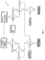
- FIG. 2 illustrates the controller logic of the present invention.
- Figure 3 is a chart illustrating how the controller activates the recirculation pump and vent valve to maintain tank pressure and liquid vapor pressure.
- Figure 1 illustrates a preferred embodiment of the fluid management system of the present invention, designated generally as 10.
- Fluid management system 10 is utilized with a zero gravity cryogenic storage system, designated generally as 12.
- a recirculation pump 14 located external the zero gravity cryogenic storage system 12 receives fluid from the storage system 12 via a main feed line 16.
- Main feed line 16 is used to provide cryogenic fluid to the cryogenic system main shut off valve 18.
- Shut off valve 18 may be, for example, a pre-valve for an engine, a main engine valve, or a power generation isolation valve.
- a recirculation pump inlet line 20 is located in close proximity to the main shut off valve 18 in order to thermally condition the main feed line 16 up to the main shut off valve 18.
- a chill/fill valve 22 (which will be discussed in detail below) is normally open to allow flow from the storage system 12 to the recirculation pump 14 inlet.
- the recirculation pump output flow 24 is divided into a first portion 26 and a second portion 28.
- the first portion or spray injection flow 26 is introduced to an internal axial spray injection system, designated generally as 30.
- the cryogenic storage system 12 comprises a storage tank which is used to store subcritical cryogenic fluid.
- the storage tank 12 may be, for example, spherical or cylindrical. It is formed of a suitable material used to store cryogens. It includes a suitable thermal protection system typically comprising a foam, multi-layered insulation or vacuum jacketed insulation.
- the storage system 12 may also contain a liquid acquisition system 32 for zero gravity fluid control, as will be discussed in more detail below.
- Storage system 12 also includes appropriate pressure and temperature instrumentation, designated as 34 and 36, respectively, to monitor storage tank pressure and fluid temperature. These measurements are input to a controller 38 to activate the recirculation pump 14 and a vent valve 40, as explained below.
- the recirculation pump 14 preferably comprises a centrifugal axial flow pump which is electrically driven by alternating current or direct current.
- Alternate driving means may include a gas turbine.
- the recirculation pump may alternatively be a positive displacement pump, which is electrically or pneumatically driven.
- the internal axial spray injection system 30 is designed to thermally de-stratify liquid and gaseous cryogenic fluids stored in the storage system through forced convection mixing. It preferably comprises an axially positioned spray bar system with a plurality of equally spaced orifices resulting in a uniform spray injection flow rate.
- the vent flow 28 is utilized to reject heat from the storage system 12.
- the flow 28 is directed through the external. vent valve 40 and through a flow control external expansion orifice 42.
- the flow is then directed through an internal heat exchanger 44.
- Heat exchanger 44 is preferably a parallel flow heat exchanger of concentric tube design with the vent flow 28 flowing through a passage between an inner tube 45 and an outer concentric tube 47, with the inner tube 45 containing the spray injection flow 26.
- the vent flow 28 is collected by a vent tube 49 and is discharged overboard via a back pressure orifice 46.
- the back pressure orifice 46 is provided for establishing a desired heat exchanger pressure level.
- Spray injection flow 26 is manifolded at the top (outlet) of the heat exchanger 44 and is directed to spray injection tubes of the spray injection system 30.
- An alternate heat exchanger design could comprise the vent flow 28 wrapped around the spray injection system 30 in a spiral-type heat exchanger configuration.
- the controller 38 activates the recirculation pump 14 by sending an electrical current to power the recirculation pump 14.
- the pump 14 draws liquid from the storage tank 12 through the use of the liquid acquisition system 32 and injects it into the stratified ullage gas, designated by numeral 48. (The liquid in Figure 1 is designated by numeral designation 50.)
- the controller allows separate control of the recirculation pump 14 and external vent valve 40.
- the input parameters include storage tank pressure 34 and recirculation pump inlet temperature 35, input load values P max , P min , and ⁇ P.
- the temperature measurement is converted to a liquid saturated pressure (P s ) through a third order equation, and is compared to the tank pressure level 34 to determine the desired liquid subcooling.
- the external vent valve 40 can only be activated if the recirculation pump 14 is activated.
- the control logic 52 only opens the vent valve 40 if the recirculation pump 14 is ON and the temperature is greater than the maximum allowable level pre-set in the controller 38.
- Opening of the vent valve allows a small flow rate, controlled by the orifice 42 downstream of the vent valve 40, to enter the heat exchanger 44. Since the vent flow expands to a low pressure, the fluid entering the heat exchanger 44 flashes to liquid and gas at a lower temperature. The temperature sink is predetermined by the restriction in the back pressure orifice 46. Because the recirculation pump 14 is also ON when the vent valve 40 is open, the overboard vent flow absorbs heat from the liquid spray injection flow.
- the design of the heat exchanger 44 is such that the vent flow is completely vaporized to a gas and is rejected to vacuum as a super heated gas approaching the liquid spray injection temperature. In this way, the heat capacity of the vent flow is increased above the normal heat of evaporation value since it also includes a degree of vapor super heating.
- FIG. 3 the pump and vent valve operations are shown for a typical tank pressure control band.
- tank pressure collapse through spray injection is sufficient through the activation of the recirculation pump 14, without heat rejection through overboard venting.
- the vent valve is activated in conjunction with the recirculation pump operation to reject heat and control tank pressure through overboard venting. This minimizes the net loss of cryogens during idle mode tank pressure control.
- the fluid management system 10 preferably includes a fill line assembly comprising a fill line 54 and the chill/fill valve 22.
- the fill line 54 receives cryogenic filling fluid from an external cryogenic re-supply source (not shown) and provides the filling fluid to the recirculation pump 14.
- the chill/fill valve 22 is so positioned to operate in a closed position to prevent the cryogenic filling fluid from being introduced directly to the zero gravity storage system 12, thereby preventing the bypassing of the spray injection system 30 so as to thermally chill the zero gravity storage system 12.
- the chill/fill valve is opened to allow simultaneous introduction of the filling fluid to the recirculation pump 14 and direct filling of the storage system through the main feedline 16 and liquid acquisition system 32.
- the present invention can be used to calculate the cryogenic liquid quantity in a zero gravity environment by using the measured tank pressure 34 and fluid temperature 36 in conjunction with a known non-condensible gas quantity. Because the liquid and gas can be thermally destratified through spray injection mixing to accomplish a uniform temperature in both the ullage gas and liquid bulk, a simple pressure-volume-temperature (P-V-T) calculation can be performed to estimate the volume occupied by the known quantity of non-condensible gas, which is an input value 56 to a computational system 58. From the ullage volume, the liquid volume and liquid mass can be calculated. This approach is valid for either a single large bubble or a multitude of small bubbles. This invention greatly simplifies alternate means of defining subcritical cryogenic fluid quantities such propellant settling thrust maneuvers, or complex radio isotope gauging systems.
- a liquid acquisition system 32 is required with the zero gravity quantity gauging system.
- the liquid acquisition system 32 comprises a screen located adjacent the inner surface of the storage tank for providing liquid retention through surface tension effects.
- the invention may be summarized as follows:
Landscapes
- Engineering & Computer Science (AREA)
- Mechanical Engineering (AREA)
- General Engineering & Computer Science (AREA)
- Health & Medical Sciences (AREA)
- Life Sciences & Earth Sciences (AREA)
- Biodiversity & Conservation Biology (AREA)
- Environmental & Geological Engineering (AREA)
- Environmental Sciences (AREA)
- General Health & Medical Sciences (AREA)
- Toxicology (AREA)
- Remote Sensing (AREA)
- Aviation & Aerospace Engineering (AREA)
- Filling Or Discharging Of Gas Storage Vessels (AREA)
Abstract
Description
- This invention relates generally to cryogenic storage systems and more particularly to a cryogenic fluid management system for zero gravity applications.
- Long term storage of sub-critical cryogens in space must address the problem of thermal stratification in storage tanks, and associated feed systems. Due to the absence of gravity induced body forces, thermal stratification in zero gravity can be much more severe than commonly experienced in a one G environment. If left uncontrolled, the thermal gradients in zero gravity will result in excessive tank pressure rise and formation of undesirable liquid and vapor mixtures within the liquid bulk, liquid acquisition system, and liquid transfer lines.
- Under zero gravity conditions, gases in any storage tank for liquids may occur in any physical location within the interior of the tank, for example, either at the top of the tank, the bottom of the tank, or any intermediate section thereof.
- A vehicle adapted to be subjected to the zero gravity operating environment of outer space may include a storage tank for liquids wherein solar heat input will increase the pressure of the tank and gases must be vented from the tank to prevent overpressurization and rupture. A special problem is thus presented in that it is necessary to vent only the gas from the system without loss of all liquid stored in the tank.
- State of the art thermodynamic venting system concepts have only addressed issues associated with the tank. Typically, only the liquid bulk has been considered. Ullage, feedline, or zero gravity liquid acquisition devices (screens, capillary channels), have not been included in the total thermal destratification system design. Also, the performance of previous thermodynamic venting concepts has relied on complex analyses to characterize the zero gravity fluid mixing and heat transfer phenomenon.
- U.S. Patent No. 3,105,361, entitled "Zero Gravity Vent System", issued to L. R. Bell, discloses the utilization of a centrifuge to separate the liquid and vapor phases of the fluid withdrawn from a cryogenic storage tank which is subsequently used to generate power to compress the withdrawn two-phase fluid and also to chill the liquid fluid phase across a heat exchanger prior to returning it to the cryogenic storage tank. Pressure reduction in the cryogenic liquid tank in this concept always results in overboard fluid venting losses. The venting loss increases if the fluid straight from cryogenic liquid tank is primarily of liquid phase with the presence of liquid droplets in the overboard discharge flow.
- U.S. Patent No. 4,412,851, entitled "Cryogenic Apparatus Suitable for Operations in Zero Gravity" issued to R. Laine, discloses the utilization of a phase separator inside a storage tank to absorb heat from the bulk fluid through fluid evaporation heat transfer and subsequent fluid venting. The heat transfer rate between the phase separator and the liquid bulk is not enhanced above the zero gravity natural convection heat transfer mode. Consequently venting losses are high due to an inefficient internal tank heat transfer rate.
- U.S. Patent No. 3,693,367, entitled "Thermodynamic Control Device" issued to L. J. DiPeri, discloses the utilization of a surface tension device to establish a gaseous barrier between liquid inside a container and a tank wall. Complete structural isolation of liquid from a containment wall is maintained, thereby minimizing heat transfer. The DiPeri device is designed only to minimize the heat transfer to the liquid and does not address the issues associated with zero gravity venting or fluid management.
- U.S. Patent No. 3,304,729, entitled "Cryogenic Storage System" issued to W. A. Chandler et al, U.S. Patent No. 3,699,696, entitled "Cryogenic Storage and Expulsion Means", issued to R. L. Rhoton and U.S. Patent 4,821,907, entitled "Surface Tension Confined Liquid Cryogen Cooler", issued to S. H. Castles et al., also address the issues associated with minimizing heat leakage to cryogenic liquid storage systems.
- It is a principal object of the present invention to provide a simple and efficient thermodynamic vent system for zero gravity pressure control that can be characterized through one G test without extensive zero gravity flight testing.
- It is another object of the present invention to integrate various fluid management functions such as tank chill/fill, zero gravity quantity gauging, feed system thermal conditioning external to the tank and liquid acquisition thermal conditioning located within the tank.
- These and other objects are accomplished by the present invention which is a fluid management system for a zero gravity cryogenic storage system. The fluid management system comprises a mixing/recirculation system. The mixing/recirculation system includes an external recirculation pump for receiving fluid from a zero gravity storage system and returning an output flow of the fluid to the storage system. An internal axial spray injection system is provided for receiving a portion of the output flow from the recirculation pump. The spray injection system thermally de-stratifies liquid and gaseous cryogenic fluid stored in the storage system.
- The fluid management system preferably includes a heat rejection system which comprises an external vent valve for receiving a second portion of the output flow from the recirculation pump. An external expansion orifice receives an output flow from the vent valve. An internal heat exchanger receives an output flow from the expansion orifice for absorbing heat from the portion of the output flow from the recirculation pump which was directed through the spray injection system. A back pressure orifice vents the heat exchanger output flow to establish a desired pressure level.
- A fill line assembly is preferably utilized to provide tank chill and liquid fill without overboard venting. The present invention also provides thermal conditioning of transfer lines, valves and engine/power generation components external the storage tank through liquid recirculation, and liquid acquisition devices internal to the storage tank. It can also be used as a means for determining liquid quantity in a zero gravity space environment.
- In contradistinction to U.S. Patent No. 3,105,361, discussed above, the present invention provides pressure reduction through internal tank fluid mixing and ullage gas condensation resulting from liquid recirculation and liquid spray injection, without overboard venting losses. Tank pressure control can be achieved by thermal destratification without venting for extended storage durations (up to 45 days) by absorbing the heat leakage in the liquid bulk. When heat rejection through venting is desired the overboard discharge flow is always in the superheated gaseous phase with no liquid droplet present, resulting in optimum heat rejection performance.
- In contradistinction to U.S. Patent No. 4,412,851, also discussed above, the heat transfer rate of the present invention is through forced convection. This is several orders of magnitude higher than the zero gravity natural convection heat transfer rate relied upon by the '851 process. Consequently, the venting durations and venting losses are minimized.
- It is also noted that since the active components (i.e. pump, valve) are located external to the storage tank ground check-out and replacement are simplified, resulting in cost and turnaround schedule reductions. Also, no electrical power penetration of the tank is required, which is especially significant for LO₂ storage systems in reducing potential ignition hazards.
- Other objects, advantages and novel features of the present invention will become apparent from the following detailed description of the invention when considered in conjunction with the accompanying drawings.
- Figure 1 is a partial cross-sectional view taken through the center of a cryogenic storage system diagramatically illustrating the features of the present invention, said view also showing external system components and connections therefor.
- Figure 2 illustrates the controller logic of the present invention.
- Figure 3 is a chart illustrating how the controller activates the recirculation pump and vent valve to maintain tank pressure and liquid vapor pressure.
- The same elements or parts throughout the figures of the drawings are designated by the same reference characters.
- Referring now to the drawings and the characters of reference marked thereon, Figure 1 illustrates a preferred embodiment of the fluid management system of the present invention, designated generally as 10.
Fluid management system 10 is utilized with a zero gravity cryogenic storage system, designated generally as 12. Arecirculation pump 14 located external the zero gravitycryogenic storage system 12 receives fluid from thestorage system 12 via amain feed line 16.Main feed line 16 is used to provide cryogenic fluid to the cryogenic system main shut offvalve 18. Shut offvalve 18 may be, for example, a pre-valve for an engine, a main engine valve, or a power generation isolation valve. - A recirculation
pump inlet line 20 is located in close proximity to the main shut offvalve 18 in order to thermally condition themain feed line 16 up to the main shut offvalve 18. A chill/fill valve 22 (which will be discussed in detail below) is normally open to allow flow from thestorage system 12 to therecirculation pump 14 inlet. The recirculationpump output flow 24 is divided into afirst portion 26 and asecond portion 28. The first portion orspray injection flow 26 is introduced to an internal axial spray injection system, designated generally as 30. - The
cryogenic storage system 12 comprises a storage tank which is used to store subcritical cryogenic fluid. Thestorage tank 12 may be, for example, spherical or cylindrical. It is formed of a suitable material used to store cryogens. It includes a suitable thermal protection system typically comprising a foam, multi-layered insulation or vacuum jacketed insulation. Thestorage system 12 may also contain aliquid acquisition system 32 for zero gravity fluid control, as will be discussed in more detail below. -
Storage system 12 also includes appropriate pressure and temperature instrumentation, designated as 34 and 36, respectively, to monitor storage tank pressure and fluid temperature. These measurements are input to acontroller 38 to activate therecirculation pump 14 and avent valve 40, as explained below. - The
recirculation pump 14 preferably comprises a centrifugal axial flow pump which is electrically driven by alternating current or direct current. Alternate driving means may include a gas turbine. The recirculation pump may alternatively be a positive displacement pump, which is electrically or pneumatically driven. - The internal axial spray injection system 30 is designed to thermally de-stratify liquid and gaseous cryogenic fluids stored in the storage system through forced convection mixing. It preferably comprises an axially positioned spray bar system with a plurality of equally spaced orifices resulting in a uniform spray injection flow rate.
- The
vent flow 28 is utilized to reject heat from thestorage system 12. Theflow 28 is directed through the external. ventvalve 40 and through a flow controlexternal expansion orifice 42. The flow is then directed through aninternal heat exchanger 44.Heat exchanger 44 is preferably a parallel flow heat exchanger of concentric tube design with thevent flow 28 flowing through a passage between aninner tube 45 and an outerconcentric tube 47, with theinner tube 45 containing thespray injection flow 26. Thevent flow 28 is collected by avent tube 49 and is discharged overboard via aback pressure orifice 46. Theback pressure orifice 46 is provided for establishing a desired heat exchanger pressure level. Sprayinjection flow 26 is manifolded at the top (outlet) of theheat exchanger 44 and is directed to spray injection tubes of the spray injection system 30. An alternate heat exchanger design could comprise thevent flow 28 wrapped around the spray injection system 30 in a spiral-type heat exchanger configuration. - In operation, when the tank pressure, sensed by the
pressure transducer 34, reaches the maximum desired level pre-set in thecontroller 38, thecontroller 38 activates therecirculation pump 14 by sending an electrical current to power therecirculation pump 14. Thepump 14 draws liquid from thestorage tank 12 through the use of theliquid acquisition system 32 and injects it into the stratified ullage gas, designated bynumeral 48. (The liquid in Figure 1 is designated bynumeral designation 50.) - The forced convection heat transfer established between the liquid spray injection flow and the
ullage gas 48 results in ullage gas chill down and pressure decay. The heat in theullage gas 48 is transferred into theliquid bulk 50 through continuous liquid spray injection and bulk mixing. When the pressure level, sensed by thepressure transducer 34, reaches the lower limit defined in thecontroller 38, the electrical power to therecirculation pump 14 is terminated. Initially, pressure control is achieved through liquid spray injection mixing without any venting losses. This mode of operation continues until the liquid bulk temperature, as indicated by thetemperature sensor 36, reaches a maximum desired level established in thecontroller 38. To prevent further rise in liquid bulk temperature, heat must be rejected from thestorage system 12. This is accomplished by the opening of thevent valve 40 located downstream of therecirculation pump 14. - Referring now to Figure 2, the control logic is illustrated, designated generally as 52. The controller allows separate control of the
recirculation pump 14 andexternal vent valve 40. The input parameters includestorage tank pressure 34 and recirculation pumpinlet temperature 35, input load values Pmax, Pmin, and ΔP. The temperature measurement is converted to a liquid saturated pressure (Ps) through a third order equation, and is compared to thetank pressure level 34 to determine the desired liquid subcooling. Theexternal vent valve 40 can only be activated if therecirculation pump 14 is activated. Thecontrol logic 52 only opens thevent valve 40 if therecirculation pump 14 is ON and the temperature is greater than the maximum allowable level pre-set in thecontroller 38. Opening of the vent valve allows a small flow rate, controlled by theorifice 42 downstream of thevent valve 40, to enter theheat exchanger 44. Since the vent flow expands to a low pressure, the fluid entering theheat exchanger 44 flashes to liquid and gas at a lower temperature. The temperature sink is predetermined by the restriction in theback pressure orifice 46. Because therecirculation pump 14 is also ON when thevent valve 40 is open, the overboard vent flow absorbs heat from the liquid spray injection flow. The design of theheat exchanger 44 is such that the vent flow is completely vaporized to a gas and is rejected to vacuum as a super heated gas approaching the liquid spray injection temperature. In this way, the heat capacity of the vent flow is increased above the normal heat of evaporation value since it also includes a degree of vapor super heating. - Referring now to Figure 3, the pump and vent valve operations are shown for a typical tank pressure control band. Initially, tank pressure collapse through spray injection is sufficient through the activation of the
recirculation pump 14, without heat rejection through overboard venting. When a liquid temperature at the recirculation pump reaches the maximum desired level, the vent valve is activated in conjunction with the recirculation pump operation to reject heat and control tank pressure through overboard venting. This minimizes the net loss of cryogens during idle mode tank pressure control. - Referring again now to Figure 1, the
fluid management system 10 preferably includes a fill line assembly comprising afill line 54 and the chill/fill valve 22. Thefill line 54 receives cryogenic filling fluid from an external cryogenic re-supply source (not shown) and provides the filling fluid to therecirculation pump 14. The chill/fill valve 22 is so positioned to operate in a closed position to prevent the cryogenic filling fluid from being introduced directly to the zerogravity storage system 12, thereby preventing the bypassing of the spray injection system 30 so as to thermally chill the zerogravity storage system 12. When the storage tank has been sufficiently chilled, the chill/fill valve is opened to allow simultaneous introduction of the filling fluid to therecirculation pump 14 and direct filling of the storage system through themain feedline 16 andliquid acquisition system 32. This procedure insures that the liquid acquisition system is filled with liquid and flushed free of vapor bubbles. This accomplishes a no vent fill with continuous ullage gas condensation through use of ullage gas spray injection. If liquid bulk thermal conditioning is required, it can be accomplished through the opening of thevent valve 40 and subsequent heat rejection. - Still referring to Figure 1, it can be seen that the present invention can be used to calculate the cryogenic liquid quantity in a zero gravity environment by using the measured
tank pressure 34 andfluid temperature 36 in conjunction with a known non-condensible gas quantity. Because the liquid and gas can be thermally destratified through spray injection mixing to accomplish a uniform temperature in both the ullage gas and liquid bulk, a simple pressure-volume-temperature (P-V-T) calculation can be performed to estimate the volume occupied by the known quantity of non-condensible gas, which is aninput value 56 to acomputational system 58. From the ullage volume, the liquid volume and liquid mass can be calculated. This approach is valid for either a single large bubble or a multitude of small bubbles. This invention greatly simplifies alternate means of defining subcritical cryogenic fluid quantities such propellant settling thrust maneuvers, or complex radio isotope gauging systems. - In order to prevent loss of the non-condensible pressure during tank venting operations, a
liquid acquisition system 32 is required with the zero gravity quantity gauging system. Theliquid acquisition system 32 comprises a screen located adjacent the inner surface of the storage tank for providing liquid retention through surface tension effects. - Obviously, many modifications and variations of the present invention are possible in light of the above teachings. It is, therefore, to be understood that within the scope of the appended claims, the invention may be practiced otherwise than as specifically described.
- What is claimed and desired to be secured by Letters Patent of the United States is:
It should be noted that the objects and advantages of the invention may be attained by means of any compatible combination(s) Particularly pointed out in the items of the following summary of the invention and the appended claims. -
- 1. A fluid management system for a zero gravity cryogenic storage system, comprising:
a mixing/recirculation system, comprising:- a) an external recirculation pump for receiving fluid from a zero gravity storage system and returning an output flow of said fluid to said storage system; and
- b) an internal axial spray injection system for receiving a portion of said output flow from said recirculation pump, said spray injection system for thermally de-stratifying liquid and gaseous cryogenic fluid stored in said storage system.
- 2. The fluid management system of 1, further comprising:
a heat rejection system, comprising:- a) an external vent valve for receiving a second portion of said output flow from said recirculation pump;
- b) an external expansion orifice for receiving an output flow from said vent valve;
- c) an internal heat exchanger for receiving an output flow from said expansion orifice for absorbing heat from said portion of the output flow from said recirculation pump which was directed through said spray injection system, said heat exchanger having an output flow; and,
- d) a back pressure orifice for establishing a desired heat exchanger pressure level.
- 3. The fluid management system of 2, wherein said mixing/recirculation system comprises a controller for initiating and terminating recirculation pump operation at a desired storage system fluid pressure range without activating said heat rejection system, thereby accomplishing pressure control without storage system fluid venting losses.
- 4. The fluid management system of 3, wherein said controller includes means for initiating and terminating said control valve operation in a desired storage system fluid temperature range so as to control fluid bulk temperature by heat rejection through overboard venting.
- 5. The fluid management system of 1 further including a fill line assembly, said fill line assembly comprising:
a fill line for receiving cryogenic filling fluid from an external cryogenic resupply source and providing said filling fluid to said recirculation pump; and,
a chill/fill valve so positioned to operate in a closed position to prevent said cryogenic filling fluid from being introduced directly to said zero gravity storage system and preventing the bypassing of said spray injection system so as to thermally chill said zero gravity storage system,
said chill/fill valve being operable in a normally open position to allow simultaneous introduction of said filling fluid to said recirculation pump and direct filling of said storage system, thereby accomplishing no vent fill with continuous ullage gas condensation through use of said spray injection system. - 6. The fluid management system of 1 further including means for calculating the cryogenic liquid quantity of fluid in said zero gravity storage system based on a known quantity of non-condensible gas in said storage system and measure values of pressure and fluid temperature in said storage system.
- 7. The fluid management system of 2 wherein said internal axial spray injection system comprises an axially positioned spray bar system with a plurality of equally spaced orifices.
- 8. The fluid management system of 7 wherein said internal heat exchanger comprises a parallel flow concentric heat exchanger.
- 9. A zero gravity cryogenic storage and transfer system, comprising:
- a) a storage tank;
- b) a zero gravity liquid acquisition system comprising screen means located adjacent an inner surface of said storage tank for providing surface tension effects; and
- c) a fluid management system, comprising a mixing/recirculation system, comprising:
- i) an external recirculation pump for receiving fluid from said storage tank; and
- ii) an internal axial spray injection system for receiving a portion of an output flow from said recirculation pump, said spray injection system for thermally destratifying liquid and gaseous cryogenic fluid stored in said storage tank.
- 10. The zero gravity cryogenic storage and transfer system of Claim 9 from wherein said fluid management system further comprises:
a heat rejection system, comprising:- a) an external vent valve for receiving a second portion of said output flow from said recirculation pump;
- b) an external expansion orifice for receiving an output flow from said vent valve;
- c) an internal heat exchanger for receiving an output flow from said expansion orifice for absorbing heat from said portion of the output flow from said recirculation pump which was directed through said spray injection system, said heat exchanger having an output flow; and,
- d) a back pressure orifice for establishing a desired heat exchanger pressure level.
- 11. The zero gravity cryogenic storage and transfer system of 10, wherein said mixing/recirculation system comprises a controller for initiating and terminating recirculation pump operation at a desired storage system fluid pressure range without activating said heat rejection system, thereby accomplishing pressure control without storage system fluid venting losses.
- 12. The zero gravity cryogenic storage and transfer system of 11 wherein said controller includes means for initiating and terminating said control valve operation in a desired storage system fluid temperature range so as to control fluid bulk temperature by heat rejection through overboard venting.
- 13. The zero gravity cryogenic storage and transfer system of 12, further comprising a fill line assembly, said fill line assembly comprising:
a fill line for receiving cryogenic filling fluid from an external cryogenic resupply source and providing said filling fluid to said recirculation pump; and,
a chill/fill valve so positioned to operate in a closed position to prevent said cryogenic filling fluid from being introduced directly to said zero gravity storage system and preventing the bypassing of said spray injection system so as to thermally chill said zero gravity storage system,
said chill/fill valve being operable in a normally open position to allow simultaneous introduction of said filling fluid to said recirculation pump and direct filling of said storage system, thereby accomplishing no vent fill with continuous ullage gas condensation through use of said spray injection system.
Claims (10)
- A fluid management system for a zero gravity cryogenic storage system, comprising:
a mixing/recirculation system, comprising:a) an external recirculation pump for receiving fluid from a zero gravity storage system and returning an output flow of said fluid to said storage system; andb) an internal axial spray injection system for receiving a portion of said output flow from said recirculation pump, said spray injection system for thermally de-stratifying liquid and gaseous cryogenic fluid stored in said storage system. - The fluid management system of Claim 1, further comprising:
a heat rejection system, comprising:a) an external vent valve for receiving a second portion of said output flow from said recirculation pump;b) an external expansion orifice for receiving an output flow from said vent valve;c) an internal heat exchanger for receiving an output flow from said expansion orifice for absorbing heat from said portion of the output flow from said recirculation pump which was directed through said spray injection system, said heat exchanger having an output flow; and,d) a back pressure orifice for establishing a desired heat exchanger pressure level. - The fluid management system of Claim 2, wherein said mixing/recirculation system comprises a controller for initiating and terminating recirculation pump operation at a desired storage system fluid pressure range without activating said heat rejection system, thereby accomplishing pressure control without storage system fluid venting losses.
- The fluid management system of Claim 3, wherein said controller includes means for initiating and terminating said control valve operation in a desired storage system fluid temperature range so as to control fluid bulk temperature by heat rejection through overboard venting.
- The fluid management system of Claim 1 further including a fill line assembly, said fill line assembly comprising:
a fill line for receiving cryogenic filling fluid from an external cryogenic re-supply source and providing said filling fluid to said recirculation pump; and,
a chill/fill valve so positioned to operate in a closed position to prevent said cryogenic filling fluid from being introduced directly to said zero gravity storage system and preventing the bypassing of said spray injection system so as to thermally chill said zero gravity storage system,
said chill/fill valve being operable in a normally open position to allow simultaneous introduction of said filling fluid to said recirculation pump and direct filling of said storage system, thereby accomplishing no vent fill with continuous ullage gas condensation through use of said spray injection system. - The fluid management system of Claim 1 further including means for calculating the cryogenic liquid quantity of fluid in said zero gravity storage system based on a known quantity of non-condensible gas in said storage system and measure values of pressure and fluid temperature in said storage system,
wherein preferably said internal axial spray injection system comprises an axially positioned spray bar system with a plurality of equally spaced orifices, and
wherein preferably said internal heat exchanger comprises a parallel flow concentric heat exchanger. - A zero gravity cryogenic storage and transfer system, comprising:a) a storage tank;b) a zero gravity liquid acquisition system comprising screen means located adjacent an inner surface of said storage tank for providing surface tension effects; andc) a fluid management system, comprising a mixing/recirculation system, comprising:i) an external recirculation pump for receiving fluid from said storage tank; andii) an internal axial spray injection system for receiving a portion of an output flow from said recirculation pump, said spray injection system for thermally destratifying liquid and gaseous cryogenic fluid stored in said storage tank.
- The zero gravity cryogenic storage and transfer system of Claim 9 from wherein said fluid management system further comprises:
a heat rejection system, comprising:a) an external vent valve for receiving a second portion of said output flow from said recirculation pump;b) an external expansion orifice for receiving an output flow from said vent valve;c) an internal heat exchanger for receiving an output flow from said expansion orifice for absorbing heat from said portion of the output flow from said recirculation pump which was directed through said spray injection system, said heat exchanger having an output flow; and,d) a back pressure orifice for establishing a desired heat exchanger pressure level, and
wherein preferably said mixing/recirculation system comprises a controller for initiating and terminating recirculation pump operation at a desired storage system fluid pressure range without activating said heat rejection system, thereby accomplishing pressure control without storage system fluid venting losses. - The zero gravity cryogenic storage and transfer system of Claim 11 wherein said controller includes means for initiating and terminating said control valve operation in a desired storage system fluid temperature range so as to control fluid bulk temperature by heat rejection through overboard venting, and
further comprising preferably a fill line assembly, said fill line assembly comprising:
a fill line for receiving cryogenic filling fluid from an external cryogenic resupply source and providing said filling fluid to said recirculation pump; and,
a chill/fill valve so positioned to operate in a closed position to prevent said cryogenic filling fluid from being introduced directly to said zero gravity storage system and preventing the bypassing of said spray injection system so as to thermally chill said zero gravity storage system,
said chill/fill valve being operable in a normally open position to allow simultaneous introduction of said filling fluid to said recirculation pump and direct filling of said storage system, thereby accomplishing no vent fill with continuous ullage gas condensation through use of said spray injection system. - A fluid management system for a cryogenic storage system, comprising:
a system, comprising:a) an external pump for receiving fluid from a storage system and returning an output flow of said fluid to said storage system; andb) an internal axial spray injection system.
Applications Claiming Priority (2)
| Application Number | Priority Date | Filing Date | Title |
|---|---|---|---|
| US64326 | 1979-08-06 | ||
| US08/064,326 US5398515A (en) | 1993-05-19 | 1993-05-19 | Fluid management system for a zero gravity cryogenic storage system |
Publications (2)
| Publication Number | Publication Date |
|---|---|
| EP0625672A1 true EP0625672A1 (en) | 1994-11-23 |
| EP0625672B1 EP0625672B1 (en) | 1997-01-29 |
Family
ID=22055161
Family Applications (1)
| Application Number | Title | Priority Date | Filing Date |
|---|---|---|---|
| EP94107569A Expired - Lifetime EP0625672B1 (en) | 1993-05-19 | 1994-05-16 | Fluid management system for a zero gravity cryogenic storage system |
Country Status (4)
| Country | Link |
|---|---|
| US (1) | US5398515A (en) |
| EP (1) | EP0625672B1 (en) |
| JP (1) | JPH0710099A (en) |
| DE (1) | DE69401617T2 (en) |
Cited By (7)
| Publication number | Priority date | Publication date | Assignee | Title |
|---|---|---|---|---|
| EP1033301A3 (en) * | 1999-03-04 | 2001-07-18 | The Boeing Company | Combined diffuser and recirculation manifold in a propellant or oxidizer tank |
| DE10005214A1 (en) * | 2000-02-05 | 2001-08-09 | Messer Austria Gmbh Gumpoldski | Low temperature tank has liquid outlet pipe for drawing off liquid at bottom and has gas supply pipe passing in through bottom of container to open out inside in the upper region |
| FR2933475A1 (en) * | 2008-07-04 | 2010-01-08 | Snecma | CRYOGENIC LIQUID STORAGE SYSTEM FOR SPACE ENGINE |
| RU2497730C1 (en) * | 2012-04-09 | 2013-11-10 | Открытое акционерное общество "Ракетно-космическая корпорация "Энергия" имени С.П. Королева" | Spacecraft power plant (versions) and method of its operation |
| CN108854166A (en) * | 2018-05-28 | 2018-11-23 | 西安交通大学 | A kind of space liquid acquisition device based on the linkage of metal mesh curtain pressure at both sides |
| EP3537026A1 (en) * | 2018-03-06 | 2019-09-11 | L'air Liquide, Societe Anonyme Pour L'etude Et L'exploitation Des Procedes Georges Claude | System, device and method for controlling the pressure of a fluid tank |
| CN116853521A (en) * | 2023-04-19 | 2023-10-10 | 上海空间推进研究所 | Board-net composite microgravity fluid full management device and assembly method |
Families Citing this family (31)
| Publication number | Priority date | Publication date | Assignee | Title |
|---|---|---|---|---|
| US5644920A (en) * | 1995-09-25 | 1997-07-08 | Rockwell International Corporation | Liquid propellant densification |
| US5901557A (en) * | 1996-10-04 | 1999-05-11 | Mcdonnell Douglas Corporation | Passive low gravity cryogenic storage vessel |
| US5936499A (en) * | 1998-02-18 | 1999-08-10 | General Electric Company | Pressure control system for zero boiloff superconducting magnet |
| US6151900A (en) * | 1999-03-04 | 2000-11-28 | Boeing Northamerican, Inc. | Cryogenic densification through introduction of a second cryogenic fluid |
| US6131397A (en) * | 1999-03-04 | 2000-10-17 | Boeing North American Inc. | Slush producing process and device |
| US6164078A (en) * | 1999-03-04 | 2000-12-26 | Boeing North American Inc. | Cryogenic liquid heat exchanger system with fluid ejector |
| US7043925B2 (en) * | 2001-01-17 | 2006-05-16 | Sierra Lobo, Inc. | Densifier for simultaneous conditioning of two cryogenic liquids |
| US7347053B1 (en) | 2001-01-17 | 2008-03-25 | Sierra Lobo, Inc. | Densifier for simultaneous conditioning of two cryogenic liquids |
| US6374618B1 (en) | 2001-02-07 | 2002-04-23 | The Boeing Company | Cryogenic fluid supply from supercritical storage system |
| JP4660966B2 (en) * | 2001-05-17 | 2011-03-30 | 株式会社Ihi | Liquid tank |
| US6904758B2 (en) * | 2003-09-26 | 2005-06-14 | Harsco Technologies Corporation | Cryogenic vessel with an ullage space venturi assembly |
| FI118681B (en) * | 2004-03-17 | 2008-02-15 | Waertsilae Finland Oy | Gas supply arrangement for a watercraft and method for producing gas in a watercraft |
| US7247765B2 (en) * | 2004-05-21 | 2007-07-24 | Exxonmobil Chemical Patents Inc. | Cracking hydrocarbon feedstock containing resid utilizing partial condensation of vapor phase from vapor/liquid separation to mitigate fouling in a flash/separation vessel |
| US7220887B2 (en) | 2004-05-21 | 2007-05-22 | Exxonmobil Chemical Patents Inc. | Process and apparatus for cracking hydrocarbon feedstock containing resid |
| US20070130962A1 (en) * | 2005-12-12 | 2007-06-14 | Blalock Clayton E | System and Method for Storing Cryogenic Liquid Air |
| WO2008064219A1 (en) * | 2006-11-22 | 2008-05-29 | Johnson Controls Technology Company | Multichannel evaporator with flow mixing manifold |
| CA2739494A1 (en) * | 2008-09-23 | 2010-04-08 | Aerovironment Inc. | Cryogenic liquid tank |
| DE102009023320B3 (en) * | 2009-05-29 | 2010-12-09 | MAX-PLANCK-Gesellschaft zur Förderung der Wissenschaften e.V. | Apparatus and method for supplying a liquefied gas to a vessel |
| US9395048B1 (en) * | 2010-07-13 | 2016-07-19 | The Boeing Company | Thermally protected liquid acquisition device for cryogenic fluids |
| US8820098B2 (en) * | 2011-05-17 | 2014-09-02 | Air Products And Chemicals, Inc. | Method and apparatus for quenching of materials in vacuum furnace |
| FR3016413B1 (en) * | 2014-01-15 | 2018-06-15 | Arianegroup Sas | THERMAL PROTECTION SYSTEM FOR A CRYOGENIC RESERVOIR OF SPACE ENGINE |
| JP6590502B2 (en) * | 2015-03-31 | 2019-10-16 | 三菱重工業株式会社 | Propellant tank and spacecraft for spacecraft |
| FR3043165B1 (en) * | 2015-10-29 | 2018-04-13 | CRYODIRECT Limited | DEVICE FOR TRANSPORTING A LIQUEFIED GAS AND METHOD FOR TRANSFERRING THE GAS THEREFROM |
| CN105699413B (en) * | 2016-02-25 | 2018-06-29 | 上海交通大学 | Work in the simulation system for thermodynamics exhaust system research of room temperature warm area |
| US20180171933A1 (en) * | 2016-12-19 | 2018-06-21 | Flight Works, Inc. | Micropump-fed autogenous pressurization system |
| CN108163398B (en) * | 2018-01-12 | 2019-09-13 | 中国矿业大学 | A high-efficiency pressure-controlled low-temperature propellant storage tank with ejection device |
| CN110566370B (en) * | 2019-08-28 | 2021-09-14 | 上海宇航系统工程研究所 | Microgravity environment small-flow precooling system |
| US11333445B1 (en) * | 2020-08-31 | 2022-05-17 | Mainstream Engineering Corporation | Modular membrane controlled three-phase deployable radiator |
| CN113074315B (en) * | 2021-03-01 | 2022-04-19 | 国网浙江省电力有限公司电力科学研究院 | Heat management system and heat management control method of hydrogen station |
| KR102793644B1 (en) * | 2022-06-21 | 2025-04-09 | 한국항공우주연구원 | Propellant exhaust system |
| CN115946877B (en) * | 2022-12-19 | 2026-03-17 | 西安交通大学 | A thermodynamic exhaust system and its control method |
Citations (5)
| Publication number | Priority date | Publication date | Assignee | Title |
|---|---|---|---|---|
| US3693367A (en) * | 1970-04-24 | 1972-09-26 | Leonard J Di Peri | Thermodynamic control device |
| US3699696A (en) * | 1970-04-20 | 1972-10-24 | Mc Donnell Douglas Corp | Cryogenic storage and expulsion means |
| US3782698A (en) * | 1972-08-11 | 1974-01-01 | Nasa | Heater-mixer for stored fluids |
| US4412851A (en) * | 1981-03-02 | 1983-11-01 | Agence Spatiale Europeene | Cryogenic apparatus suitable for operations in zero gravity |
| US4846854A (en) * | 1988-09-30 | 1989-07-11 | The United States Of America As Represented By The United States National Aeronautics And Space Administration | System for venting gas from a liquid storage tank |
Family Cites Families (10)
| Publication number | Priority date | Publication date | Assignee | Title |
|---|---|---|---|---|
| US2790307A (en) * | 1955-09-12 | 1957-04-30 | Phillips Petroleum Co | Storage of volatile liquids |
| US3087311A (en) * | 1960-07-22 | 1963-04-30 | Garrett Corp | Container for liquefied gas |
| US3105361A (en) * | 1961-11-20 | 1963-10-01 | Thompson Ramo Wooldridge Inc | Zero gravity vent system |
| US3191395A (en) * | 1963-07-31 | 1965-06-29 | Chicago Bridge & Iron Co | Apparatus for storing liquefied gas near atmospheric pressure |
| US3393367A (en) * | 1965-12-08 | 1968-07-16 | Rca Corp | Circuit for generating two consecutive same-duration pulses, each on separate outputterminals, regardless of triggering-pulse duration |
| US3486302A (en) * | 1968-02-26 | 1969-12-30 | Martin Marietta Corp | Zero or reduced gravity storage system for two phase fluid |
| US3473343A (en) * | 1968-05-10 | 1969-10-21 | United Aircraft Corp | Cold gas tank pressurizing system |
| US3650290A (en) * | 1968-11-19 | 1972-03-21 | Air Reduction | Pressure control system for cryogenic fluids |
| US4218892A (en) * | 1979-03-29 | 1980-08-26 | Nasa | Low cost cryostat |
| US4821907A (en) * | 1988-06-13 | 1989-04-18 | The United States Of America As Represented By The Administrator Of The National Aeronautics And Space Administration | Surface tension confined liquid cryogen cooler |
-
1993
- 1993-05-19 US US08/064,326 patent/US5398515A/en not_active Expired - Lifetime
-
1994
- 1994-05-16 DE DE69401617T patent/DE69401617T2/en not_active Expired - Fee Related
- 1994-05-16 EP EP94107569A patent/EP0625672B1/en not_active Expired - Lifetime
- 1994-05-19 JP JP6105355A patent/JPH0710099A/en active Pending
Patent Citations (5)
| Publication number | Priority date | Publication date | Assignee | Title |
|---|---|---|---|---|
| US3699696A (en) * | 1970-04-20 | 1972-10-24 | Mc Donnell Douglas Corp | Cryogenic storage and expulsion means |
| US3693367A (en) * | 1970-04-24 | 1972-09-26 | Leonard J Di Peri | Thermodynamic control device |
| US3782698A (en) * | 1972-08-11 | 1974-01-01 | Nasa | Heater-mixer for stored fluids |
| US4412851A (en) * | 1981-03-02 | 1983-11-01 | Agence Spatiale Europeene | Cryogenic apparatus suitable for operations in zero gravity |
| US4846854A (en) * | 1988-09-30 | 1989-07-11 | The United States Of America As Represented By The United States National Aeronautics And Space Administration | System for venting gas from a liquid storage tank |
Cited By (12)
| Publication number | Priority date | Publication date | Assignee | Title |
|---|---|---|---|---|
| EP1033301A3 (en) * | 1999-03-04 | 2001-07-18 | The Boeing Company | Combined diffuser and recirculation manifold in a propellant or oxidizer tank |
| DE10005214A1 (en) * | 2000-02-05 | 2001-08-09 | Messer Austria Gmbh Gumpoldski | Low temperature tank has liquid outlet pipe for drawing off liquid at bottom and has gas supply pipe passing in through bottom of container to open out inside in the upper region |
| DE10005214C2 (en) * | 2000-02-05 | 2002-02-28 | Messer Austria Gmbh Gumpoldski | Cryogenic tank |
| FR2933475A1 (en) * | 2008-07-04 | 2010-01-08 | Snecma | CRYOGENIC LIQUID STORAGE SYSTEM FOR SPACE ENGINE |
| EP2143988A1 (en) * | 2008-07-04 | 2010-01-13 | Snecma | Cryogenic liquid storage system for space vehicle |
| RU2529084C2 (en) * | 2008-07-04 | 2014-09-27 | Снекма | System to store cryogenic liquid for spacecraft |
| US8893514B2 (en) | 2008-07-04 | 2014-11-25 | Snecma | Cryogenic liquid storage system for a spacecraft |
| RU2497730C1 (en) * | 2012-04-09 | 2013-11-10 | Открытое акционерное общество "Ракетно-космическая корпорация "Энергия" имени С.П. Королева" | Spacecraft power plant (versions) and method of its operation |
| EP3537026A1 (en) * | 2018-03-06 | 2019-09-11 | L'air Liquide, Societe Anonyme Pour L'etude Et L'exploitation Des Procedes Georges Claude | System, device and method for controlling the pressure of a fluid tank |
| FR3078765A1 (en) * | 2018-03-06 | 2019-09-13 | L'air Liquide, Societe Anonyme Pour L'etude Et L'exploitation Des Procedes Georges Claude | SYSTEM, DEVICE AND METHOD FOR REGULATING THE PRESSURE OF A FLUID RESERVOIR |
| CN108854166A (en) * | 2018-05-28 | 2018-11-23 | 西安交通大学 | A kind of space liquid acquisition device based on the linkage of metal mesh curtain pressure at both sides |
| CN116853521A (en) * | 2023-04-19 | 2023-10-10 | 上海空间推进研究所 | Board-net composite microgravity fluid full management device and assembly method |
Also Published As
| Publication number | Publication date |
|---|---|
| JPH0710099A (en) | 1995-01-13 |
| DE69401617T2 (en) | 1997-09-11 |
| DE69401617D1 (en) | 1997-03-13 |
| EP0625672B1 (en) | 1997-01-29 |
| US5398515A (en) | 1995-03-21 |
Similar Documents
| Publication | Publication Date | Title |
|---|---|---|
| EP0625672B1 (en) | Fluid management system for a zero gravity cryogenic storage system | |
| US3699696A (en) | Cryogenic storage and expulsion means | |
| US5901557A (en) | Passive low gravity cryogenic storage vessel | |
| US5954101A (en) | Mobile delivery and storage system for cryogenic fluids | |
| EP2162670B1 (en) | Device and method for storing hydrogen for an aircraft | |
| EP1722153B1 (en) | Gas cooling using a melting/solidifying medium for high pressure storage tanks for compressed natural gas or hydrogen | |
| US9903535B2 (en) | Cryogenic liquid conditioning and delivery system | |
| JPH07174296A (en) | Cryogenic liquid storage tank | |
| US7568352B2 (en) | Thermally coupled liquid oxygen and liquid methane storage vessel | |
| US6453681B1 (en) | Methods and apparatus for liquid densification | |
| US6131395A (en) | Propellant densification apparatus and method | |
| US3473343A (en) | Cold gas tank pressurizing system | |
| US9395048B1 (en) | Thermally protected liquid acquisition device for cryogenic fluids | |
| EP1033303B1 (en) | Cryogenic densification through introduction of a second cryogenic fluid | |
| EP0670452A1 (en) | Loading, storage and delivery apparatus and method for fluid at cryogenic temperature | |
| US3962882A (en) | Method and apparatus for transfer of liquefied gas | |
| US3492793A (en) | Liquid vapor separator and cryogenic liquid converter | |
| US3147593A (en) | Fuel store | |
| Imai et al. | Basic study on thermodynamic vent system in propulsion system for future spacecraft | |
| Lak | Fluid management system for a zero gravity cryogenic storage system | |
| Stochl et al. | Autogenous pressurization of cryogenic vessels using submerged vapor injection | |
| RU2222749C2 (en) | Gas storage vessel | |
| FAZAH et al. | Design and integrated operation of an innovative thermodynamic vent system concept | |
| Stark et al. | Fluid management systems technology summaries | |
| Parmley et al. | Performance of the relativity mission superfluid helium flight dewar |
Legal Events
| Date | Code | Title | Description |
|---|---|---|---|
| PUAI | Public reference made under article 153(3) epc to a published international application that has entered the european phase |
Free format text: ORIGINAL CODE: 0009012 |
|
| AK | Designated contracting states |
Kind code of ref document: A1 Designated state(s): DE FR GB IT |
|
| 17P | Request for examination filed |
Effective date: 19941230 |
|
| 17Q | First examination report despatched |
Effective date: 19950627 |
|
| GRAG | Despatch of communication of intention to grant |
Free format text: ORIGINAL CODE: EPIDOS AGRA |
|
| GRAH | Despatch of communication of intention to grant a patent |
Free format text: ORIGINAL CODE: EPIDOS IGRA |
|
| GRAH | Despatch of communication of intention to grant a patent |
Free format text: ORIGINAL CODE: EPIDOS IGRA |
|
| GRAA | (expected) grant |
Free format text: ORIGINAL CODE: 0009210 |
|
| AK | Designated contracting states |
Kind code of ref document: B1 Designated state(s): DE FR GB IT |
|
| ITF | It: translation for a ep patent filed | ||
| ET | Fr: translation filed | ||
| REF | Corresponds to: |
Ref document number: 69401617 Country of ref document: DE Date of ref document: 19970313 |
|
| PLBE | No opposition filed within time limit |
Free format text: ORIGINAL CODE: 0009261 |
|
| STAA | Information on the status of an ep patent application or granted ep patent |
Free format text: STATUS: NO OPPOSITION FILED WITHIN TIME LIMIT |
|
| 26N | No opposition filed | ||
| REG | Reference to a national code |
Ref country code: GB Ref legal event code: IF02 |
|
| PGFP | Annual fee paid to national office [announced via postgrant information from national office to epo] |
Ref country code: IT Payment date: 20090528 Year of fee payment: 16 Ref country code: FR Payment date: 20090518 Year of fee payment: 16 Ref country code: DE Payment date: 20090528 Year of fee payment: 16 |
|
| PGFP | Annual fee paid to national office [announced via postgrant information from national office to epo] |
Ref country code: GB Payment date: 20090528 Year of fee payment: 16 |
|
| GBPC | Gb: european patent ceased through non-payment of renewal fee |
Effective date: 20100516 |
|
| REG | Reference to a national code |
Ref country code: FR Ref legal event code: ST Effective date: 20110131 |
|
| PG25 | Lapsed in a contracting state [announced via postgrant information from national office to epo] |
Ref country code: IT Free format text: LAPSE BECAUSE OF NON-PAYMENT OF DUE FEES Effective date: 20100516 |
|
| PG25 | Lapsed in a contracting state [announced via postgrant information from national office to epo] |
Ref country code: DE Free format text: LAPSE BECAUSE OF NON-PAYMENT OF DUE FEES Effective date: 20101201 |
|
| PG25 | Lapsed in a contracting state [announced via postgrant information from national office to epo] |
Ref country code: FR Free format text: LAPSE BECAUSE OF NON-PAYMENT OF DUE FEES Effective date: 20100531 |
|
| PG25 | Lapsed in a contracting state [announced via postgrant information from national office to epo] |
Ref country code: GB Free format text: LAPSE BECAUSE OF NON-PAYMENT OF DUE FEES Effective date: 20100516 |