EP0624998A1 - Safety device for heating elements in temperature-controlled home appliances - Google Patents
Safety device for heating elements in temperature-controlled home appliances Download PDFInfo
- Publication number
- EP0624998A1 EP0624998A1 EP94201204A EP94201204A EP0624998A1 EP 0624998 A1 EP0624998 A1 EP 0624998A1 EP 94201204 A EP94201204 A EP 94201204A EP 94201204 A EP94201204 A EP 94201204A EP 0624998 A1 EP0624998 A1 EP 0624998A1
- Authority
- EP
- European Patent Office
- Prior art keywords
- heating elements
- safety device
- heat
- sensitive element
- thermostat
- Prior art date
- Legal status (The legal status is an assumption and is not a legal conclusion. Google has not performed a legal analysis and makes no representation as to the accuracy of the status listed.)
- Granted
Links
Images


Classifications
-
- A—HUMAN NECESSITIES
- A47—FURNITURE; DOMESTIC ARTICLES OR APPLIANCES; COFFEE MILLS; SPICE MILLS; SUCTION CLEANERS IN GENERAL
- A47L—DOMESTIC WASHING OR CLEANING; SUCTION CLEANERS IN GENERAL
- A47L15/00—Washing or rinsing machines for crockery or tableware
- A47L15/42—Details
- A47L15/4285—Water-heater arrangements
-
- D—TEXTILES; PAPER
- D06—TREATMENT OF TEXTILES OR THE LIKE; LAUNDERING; FLEXIBLE MATERIALS NOT OTHERWISE PROVIDED FOR
- D06F—LAUNDERING, DRYING, IRONING, PRESSING OR FOLDING TEXTILE ARTICLES
- D06F34/00—Details of control systems for washing machines, washer-dryers or laundry dryers
- D06F34/14—Arrangements for detecting or measuring specific parameters
- D06F34/22—Condition of the washing liquid, e.g. turbidity
- D06F34/24—Liquid temperature
-
- H—ELECTRICITY
- H05—ELECTRIC TECHNIQUES NOT OTHERWISE PROVIDED FOR
- H05B—ELECTRIC HEATING; ELECTRIC LIGHT SOURCES NOT OTHERWISE PROVIDED FOR; CIRCUIT ARRANGEMENTS FOR ELECTRIC LIGHT SOURCES, IN GENERAL
- H05B3/00—Ohmic-resistance heating
- H05B3/78—Heating arrangements specially adapted for immersion heating
- H05B3/82—Fixedly-mounted immersion heaters
-
- D—TEXTILES; PAPER
- D06—TREATMENT OF TEXTILES OR THE LIKE; LAUNDERING; FLEXIBLE MATERIALS NOT OTHERWISE PROVIDED FOR
- D06F—LAUNDERING, DRYING, IRONING, PRESSING OR FOLDING TEXTILE ARTICLES
- D06F2103/00—Parameters monitored or detected for the control of domestic laundry washing machines, washer-dryers or laundry dryers
- D06F2103/16—Washing liquid temperature
-
- D—TEXTILES; PAPER
- D06—TREATMENT OF TEXTILES OR THE LIKE; LAUNDERING; FLEXIBLE MATERIALS NOT OTHERWISE PROVIDED FOR
- D06F—LAUNDERING, DRYING, IRONING, PRESSING OR FOLDING TEXTILE ARTICLES
- D06F39/00—Details of washing machines not specific to a single type of machines covered by groups D06F9/00 - D06F27/00
- D06F39/04—Heating arrangements
Definitions
- the present invention relates to a safety device for heating elements in temperature-controlled home appliances, such as washing machines, washer-driers, dishwashers, deep-friers and such like.
- Such overheating can be caused by the lack of the fluid to be heated, typically water in the case of washing machines, air flow in the case of washer-driers and cooking oil in the case of deep-friers.
- the absence of water inside the cylinder causes a fast increase in the temperature of the heating resistance, and the possible burning of its insulator coating; this is clearly dangerous, as it involves the formation of an electrical short-circuit when the water inside the cylinder shall once again come into contact with the resistance.
- Safety devices are known that are constituted by power supply switches triggered by devices sensitive to the external temperature of the heating resistance.
- the object of the present invention is to provide a safety device that integrates the function of controlling the temperature of the fluid.
- a safety device for heating elements in home appliances with a fluid subjected to temperature control wherein said temperature control is carried out by a thermostat having a heat-sensitive element immersed in said fluid, characterized in that said heat-sensitive element of the thermostat is also coupled thermally and mechanically, through thermally-conducting means, to said heating elements, to provide, by means of said thermostat, a combined control of the temperature of the fluid and of that of the heating elements.
- said heat-sensitive element is fastened mechanically to a flange wherein said heating elements are fastened to the chassis of the home appliance.
- the present invention it is possible to provide a safety device integrating the function of controlling the temperature of the fluid, with a consequent saving of components and thus of costs of production.
- a first type of heating element is constituted by an armoured resistance 1, provided with a flange 2 for mounting on a chassis 3 of a home appliance; the flange 2 comprises two opposite metal plates 4, between which there is interposed a rubber seal 5. It is also provided with a pair of through holes 6 wherein there are inserted as many terminals 7 of the resistance 1; a third through hole 8 allows the insertion of an immersion thermostat 9, say of the non-adjustable type with trigger temperatures of 30°C and 90°C, whose heat-sensitive element 10 is provided with an elastic clip 11 in thermally-conducting material for connecting to the resistance 1.
- the resistance 1 is located in the space between the bottom of the tank 16 and the bottom of the loading cylinder 17 (visible in Fig. 5); when the tank 16 has been filled with water, both the resistance 1 and the heat-sensitive element 10 of the thermostat 9 are immersed.
- the heating step is reached, power is applied across the terminals 7 of the resistance 1; the passage of current in the resistance 1 causes it to heat up, and the water is also consequently heated up.
- the heat-sensitive element 10 as well as controlling, in a manner known in itself, the temperature of the water during the washing cycle, also controls, through the clip 11, the temperature of the resistance 1 and, when this exceeds a given value, it triggers the switch 15 that cuts voltage from across the terminals 7 of the resistance 1.
- a second type of heating element constituted by an armoured resistance with a longer linear extension with respect to the resistance 1.
- a corresponding flange 19, similar to the flange 2, is again provided with through holes 20 wherein there are inserted as many terminals 21 of the resistance 18, and, in a central position, with a through hole 22 in which the thermostat 9 is inserted; the heat-sensitive element 10 is provided with a clamp 23 in a thermally-conducting material tightly attached to the resistance 18 by means of a rivet 24.
- a lever 25 is hinged between two brackets 26 and allows, through two cams 27 (Figs. 5 and 6), the clamping of the two plates 4 of the flange 9 so as to compress the seal 5 and consequently clamp the resistance 18 and the thermostat 9.
- thermostat 9 has, however, been replaced by a sensor bulb 29 that operates by expansion of a fluid, say, oil, inside a capillary 30 forming part of an adjustable thermostat; in such thermostats, commonly available commercially, the bulb 29 has dimensions that are unified with those of the thermostat 9.
- the sensor bulb 29 is connected to the resistance 1 by means of an elastic clip 11.
- FIG. 11 there is shown a third type of heating element constituted by an armoured resistance 31, provided with a flange 2 identical to that shown in Figs. 1, 2, 9 and 10.
- This solution again uses an adjustable thermostat provided with a fluid-expansion sensor bulb 32, that is again provided with a capillary 30 and is in thermal and mechanical contact with the resistance 31 by means of a capillary 33, containing the expandable fluid, connected to the resistance 31 by means of an elastic clip 34.
Landscapes
- Engineering & Computer Science (AREA)
- Textile Engineering (AREA)
- Control Of Resistance Heating (AREA)
- Resistance Heating (AREA)
- Electric Stoves And Ranges (AREA)
Abstract
Description
- The present invention relates to a safety device for heating elements in temperature-controlled home appliances, such as washing machines, washer-driers, dishwashers, deep-friers and such like.
- Compliance with safety regulations in force in the matter of home appliances obliges manufacturers to install suitable safety devices on such home appliances that prevent the heating elements from overheating, generally constituted by armoured resistances immersed in a liquid or other suitable fluid.
- Such overheating can be caused by the lack of the fluid to be heated, typically water in the case of washing machines, air flow in the case of washer-driers and cooking oil in the case of deep-friers. In the case, say, of a washing machine, the absence of water inside the cylinder causes a fast increase in the temperature of the heating resistance, and the possible burning of its insulator coating; this is clearly dangerous, as it involves the formation of an electrical short-circuit when the water inside the cylinder shall once again come into contact with the resistance.
- Safety devices are known that are constituted by power supply switches triggered by devices sensitive to the external temperature of the heating resistance.
- devices, however, are dedicated solely to a function of surveillance of the temperature of the heating element, separate devices being always provided to control the temperature of the fluid to be heated; the latter are constituted by thermostats endowed with heat-sensitive elements immersed in the fluid itself. This is naturally reflected on costs of production.
- In view of the state of the art, the object of the present invention is to provide a safety device that integrates the function of controlling the temperature of the fluid.
- According to the present invention such object is attained thanks to a safety device for heating elements in home appliances with a fluid subjected to temperature control, wherein said temperature control is carried out by a thermostat having a heat-sensitive element immersed in said fluid, characterized in that said heat-sensitive element of the thermostat is also coupled thermally and mechanically, through thermally-conducting means, to said heating elements, to provide, by means of said thermostat, a combined control of the temperature of the fluid and of that of the heating elements.
- According to a preferred embodiment of the present invention, said heat-sensitive element is fastened mechanically to a flange wherein said heating elements are fastened to the chassis of the home appliance.
- Thanks to the present invention it is possible to provide a safety device integrating the function of controlling the temperature of the fluid, with a consequent saving of components and thus of costs of production.
- These and other features of the present invention will be made more evident by the following detailed description of some embodiments thereof, illustrated as non-limiting examples in the enclosed drawings, wherein:
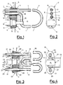
- Fig. 1 shows a partially sectioned plan view of a first type of heating element with a flange for mounting to the chassis of the home appliance, on which there is fastened a safety device according to the invention;
- Fig. 2 is a side view of said heating element with flange and safety device;
- Fig. 3 shows a partially sectioned plan view of a second type of heating element provided with said safety device, wherein the thermostat is fastened to the flange of the heating element by means of a different type of mechanical fastening means;
- Fig. 4 is a side view of the unit of Fig. 3;
- Fig. 5 is a cross-sectional view taken along the line V-V of Fig. 3;
- Fig. 6 shows a detail of the device of Fig. 3, with said mechanical fastening means in a position such as to allow the removal of the safety device;
- Fig 7 shows a partially sectioned plan view of said second type of heating element, wherein the thermostat is fastened to its mounting flange by means of a further type of mechanical fastening means;
- Fig. 8 is a side view of Fig. 7;
- Fig. 9 shows a partially sectioned plan view of a heating element similar to that of Fig. 1, but with the safety device endowed with a different type of thermostat;
- Fig. 10 is a side view of Fig. 9;
- Fig. 11 shows a partially sectioned plan view of a third type of heating element provided with a safety device according to the invention.
- With reference to Figs. 1 and 2, a first type of heating element is constituted by an
armoured resistance 1, provided with aflange 2 for mounting on achassis 3 of a home appliance; theflange 2 comprises twoopposite metal plates 4, between which there is interposed arubber seal 5. It is also provided with a pair of throughholes 6 wherein there are inserted asmany terminals 7 of theresistance 1; a third throughhole 8 allows the insertion of animmersion thermostat 9, say of the non-adjustable type with trigger temperatures of 30°C and 90°C, whose heat-sensitive element 10 is provided with anelastic clip 11 in thermally-conducting material for connecting to theresistance 1. There is also a fourth throughhole 12 for the insertion of threadedtie rod 13 thanks to which, by means of a fasteningnut 14, theseal 5 is compressed so as to clamp both theresistance 1 and thethermostat 9. The latter is also provided with anelectrical switch 15 driven by the heat-sensitive element 10. - In the case wherein the home appliance is a washing machine, the
resistance 1 is located in the space between the bottom of thetank 16 and the bottom of the loading cylinder 17 (visible in Fig. 5); when thetank 16 has been filled with water, both theresistance 1 and the heat-sensitive element 10 of thethermostat 9 are immersed. When, during a washing cycle, the heating step is reached, power is applied across theterminals 7 of theresistance 1; the passage of current in theresistance 1 causes it to heat up, and the water is also consequently heated up. The heat-sensitive element 10, as well as controlling, in a manner known in itself, the temperature of the water during the washing cycle, also controls, through theclip 11, the temperature of theresistance 1 and, when this exceeds a given value, it triggers theswitch 15 that cuts voltage from across theterminals 7 of theresistance 1. - In Figs. 3-6 there is shown a second type of heating element constituted by an armoured resistance with a longer linear extension with respect to the
resistance 1. Acorresponding flange 19, similar to theflange 2, is again provided with throughholes 20 wherein there are inserted asmany terminals 21 of theresistance 18, and, in a central position, with athrough hole 22 in which thethermostat 9 is inserted; the heat-sensitive element 10 is provided with aclamp 23 in a thermally-conducting material tightly attached to theresistance 18 by means of arivet 24. Alever 25 is hinged between twobrackets 26 and allows, through two cams 27 (Figs. 5 and 6), the clamping of the twoplates 4 of theflange 9 so as to compress theseal 5 and consequently clamp theresistance 18 and thethermostat 9. - In Figs. 7 and 8, as opposed to Figs. 3-6, the clamping of the
plates 4 of arespective flange 35 is obtained in a manner similar to that shown in Figs. 1 and 2, by means of a pair of threadedtie rods 28, and ofrespective fastening nuts 50. - In figs. 9 and 10 there is represented a unit of
resistance 1 andflange 2 identical to that shown in Figs. 1 and 2, and described previously. Thethermostat 9 has, however, been replaced by asensor bulb 29 that operates by expansion of a fluid, say, oil, inside a capillary 30 forming part of an adjustable thermostat; in such thermostats, commonly available commercially, thebulb 29 has dimensions that are unified with those of thethermostat 9. Thesensor bulb 29 is connected to theresistance 1 by means of anelastic clip 11. - Lastly, in Fig. 11 there is shown a third type of heating element constituted by an
armoured resistance 31, provided with aflange 2 identical to that shown in Figs. 1, 2, 9 and 10. This solution again uses an adjustable thermostat provided with a fluid-expansion sensor bulb 32, that is again provided with a capillary 30 and is in thermal and mechanical contact with theresistance 31 by means of a capillary 33, containing the expandable fluid, connected to theresistance 31 by means of anelastic clip 34.
Claims (7)
- Safety device for heating elements in home appliances with a fluid subjected to temperature control, wherein said temperature control is carried out by a thermostat (9) having a heat-sensitive element (10, 29, 32) immersed in said fluid, characterized in that said heat-sensitive element (10, 29, 32) of the thermostat (9) is also coupled thermally and mechanically, through thermally-conducting means (11, 23, 33), to said heating elements (1, 18, 31), to provide, by means of said thermostat (9), a combined control of the temperature of the fluid and of that of the heating elements (1, 18, 31).
- Safety device according to claim 1, characterized in that said heat-sensitive element (10, 29, 32) is mechanically fastened to a flange (2, 19, 35) with which said heating elements (1, 18, 31) are provided for their mounting on the chassis (3) of the home appliance.
- Safety device according to claim 2, characterized in that said flange (2, 19, 35) comprises two opposite metal plates (4), with the interposition of a seal (5), there being provided mechanical means (13; 25, 26, 27; 28) for compressing said seal (5) to accomplish the clamping of said heating elements (1, 18, 31) and of said heat-sensitive element (10, 29, 32).
- Safety device according to claim 3, characterized in that said mechanical means (13; 25, 26, 27; 28) are constituted by at least one threaded tie rod (13; 28) and by a respective fastening nut (4).
- Safety device according to claim 3, characterized in that said mechanical means (13; 25, 26, 27; 28) are constituted by two brackets (26) fastened to one of the plates (4) of the flange (2, 19, 35) and by a lever (25) hinged on said brackets (26) and provided with two cams (27) operating the other of said plates (4).
- Safety device according to claim 1, characterized in that said thermally-conducting means (11, 23, 33) are constituted by an elastic clip (11) for connecting to said heating elements (1), applied to the heat-sensitive element (10, 29).
- Safety device according to claim 1, characterized in that said thermally-conducting means (11, 23, 33) are constituted by a clamp (23) applied to the heat-sensitive element (10) and tightly attached to said heating elements (18) by means of a rivet (24).
Applications Claiming Priority (2)
| Application Number | Priority Date | Filing Date | Title |
|---|---|---|---|
| ITMI930942 | 1993-05-11 | ||
| IT93MI000942A IT1264405B1 (en) | 1993-05-11 | 1993-05-11 | SAFETY DEVICE FOR HEATING ELEMENTS IN TEMPERATURE CONTROLLED HOUSEHOLD APPLIANCES |
Publications (2)
| Publication Number | Publication Date |
|---|---|
| EP0624998A1 true EP0624998A1 (en) | 1994-11-17 |
| EP0624998B1 EP0624998B1 (en) | 1999-01-13 |
Family
ID=11366096
Family Applications (1)
| Application Number | Title | Priority Date | Filing Date |
|---|---|---|---|
| EP94201204A Expired - Lifetime EP0624998B1 (en) | 1993-05-11 | 1994-05-02 | Safety device for heating elements in temperature-controlled home appliances |
Country Status (4)
| Country | Link |
|---|---|
| EP (1) | EP0624998B1 (en) |
| DE (1) | DE69415860T2 (en) |
| ES (1) | ES2127345T3 (en) |
| IT (1) | IT1264405B1 (en) |
Cited By (5)
| Publication number | Priority date | Publication date | Assignee | Title |
|---|---|---|---|---|
| WO1995019129A1 (en) * | 1994-01-13 | 1995-07-20 | Strix Limited | Water heating apparatus |
| GB2306284A (en) * | 1995-07-19 | 1997-04-30 | Otter Controls Ltd | Electric heating elements |
| EP1795109A3 (en) * | 2005-12-09 | 2008-04-02 | LG Electronics Inc. | Steam generator for a suction cleaner, method of controlling same, suction cleaner using same and method of controlling the suction cleaner |
| WO2008096915A1 (en) | 2007-02-06 | 2008-08-14 | Lg Electronics Inc. | Heating apparatus, and steam generator and home appliance using the same |
| ITTO20080694A1 (en) * | 2008-09-23 | 2010-03-24 | Indesit Co Spa | WASHING MACHINE, IN PARTICULAR A WASHING MACHINE, A WASHING MACHINE OR A DISHWASHER PROVIDED WITH A TEMPERATURE DETECTION DEVICE FOR THE ELECTRIC HEATING WARMING RESISTANCE OF THE WASHING LIQUID. |
Citations (5)
| Publication number | Priority date | Publication date | Assignee | Title |
|---|---|---|---|---|
| DE1237240B (en) * | 1955-09-20 | 1967-03-23 | Licentia Gmbh | Temperature-dependent switching device |
| DE1815429A1 (en) * | 1967-12-28 | 1969-07-24 | Elpag Ag Chur | Electric heating element |
| US3750429A (en) * | 1971-03-26 | 1973-08-07 | Westinghouse Electric Corp | Control for an automatic washer |
| EP0275635A1 (en) * | 1986-12-15 | 1988-07-27 | Redring Electric Limited | Immersion heaters |
| WO1992005675A1 (en) * | 1990-09-17 | 1992-04-02 | Strix Limited | Immersion heaters |
-
1993
- 1993-05-11 IT IT93MI000942A patent/IT1264405B1/en active IP Right Grant
-
1994
- 1994-05-02 DE DE69415860T patent/DE69415860T2/en not_active Expired - Fee Related
- 1994-05-02 EP EP94201204A patent/EP0624998B1/en not_active Expired - Lifetime
- 1994-05-02 ES ES94201204T patent/ES2127345T3/en not_active Expired - Lifetime
Patent Citations (5)
| Publication number | Priority date | Publication date | Assignee | Title |
|---|---|---|---|---|
| DE1237240B (en) * | 1955-09-20 | 1967-03-23 | Licentia Gmbh | Temperature-dependent switching device |
| DE1815429A1 (en) * | 1967-12-28 | 1969-07-24 | Elpag Ag Chur | Electric heating element |
| US3750429A (en) * | 1971-03-26 | 1973-08-07 | Westinghouse Electric Corp | Control for an automatic washer |
| EP0275635A1 (en) * | 1986-12-15 | 1988-07-27 | Redring Electric Limited | Immersion heaters |
| WO1992005675A1 (en) * | 1990-09-17 | 1992-04-02 | Strix Limited | Immersion heaters |
Cited By (16)
| Publication number | Priority date | Publication date | Assignee | Title |
|---|---|---|---|---|
| WO1995019129A1 (en) * | 1994-01-13 | 1995-07-20 | Strix Limited | Water heating apparatus |
| GB2301226A (en) * | 1994-01-13 | 1996-11-27 | Strix Ltd | Water heating apparatus |
| GB2301226B (en) * | 1994-01-13 | 1998-04-22 | Strix Ltd | Control units for water heating apparatus |
| GB2306284A (en) * | 1995-07-19 | 1997-04-30 | Otter Controls Ltd | Electric heating elements |
| US8601638B2 (en) | 2005-12-09 | 2013-12-10 | Lg Electronics Inc. | Steam generator, method of controlling the same, cleaner using the same and method of controlling the cleaner |
| US7917991B2 (en) | 2005-12-09 | 2011-04-05 | Lg Electronics Inc. | Steam generator, method of controlling the same, cleaner using the same and method of controlling the cleaner |
| EP1795109A3 (en) * | 2005-12-09 | 2008-04-02 | LG Electronics Inc. | Steam generator for a suction cleaner, method of controlling same, suction cleaner using same and method of controlling the suction cleaner |
| WO2008096915A1 (en) | 2007-02-06 | 2008-08-14 | Lg Electronics Inc. | Heating apparatus, and steam generator and home appliance using the same |
| EP2118357A4 (en) * | 2007-02-06 | 2011-03-16 | Lg Electronics Inc | HEATING APPARATUS, AND STEAM GENERATOR AND HOUSEHOLD APPLIANCE USING HEATING APPARATUS AND STEAM GENERATOR |
| US8351769B2 (en) | 2007-02-06 | 2013-01-08 | Lg Electronics Inc. | Heating apparatus, and steam generator and home appliance using the same |
| ITTO20080694A1 (en) * | 2008-09-23 | 2010-03-24 | Indesit Co Spa | WASHING MACHINE, IN PARTICULAR A WASHING MACHINE, A WASHING MACHINE OR A DISHWASHER PROVIDED WITH A TEMPERATURE DETECTION DEVICE FOR THE ELECTRIC HEATING WARMING RESISTANCE OF THE WASHING LIQUID. |
| WO2010035080A1 (en) * | 2008-09-23 | 2010-04-01 | Indesit Company S.P.A. | Washing machine, in particular a laundry washing or washing/drying machine or a dishwasher, equipped with a device for detecting the temperature of the electric resistance used for warming up the wash liquid |
| RU2480544C2 (en) * | 2008-09-23 | 2013-04-27 | Индезит Компани С.П.А. | Washing machine, in particular, washing or washing-drying machine for laundry or dishwasher, method of determining submerged or protruding condition of electrical resistance used in washing machine, method for removal of lime deposits from electrical resistance |
| EP2543762A3 (en) * | 2008-09-23 | 2014-04-16 | Indesit Company S.p.A. | Method for detecting a submerged or emerged operating condition of an electric resistance used in a washing machine |
| US8882346B2 (en) | 2008-09-23 | 2014-11-11 | Indesit Company S.P.A. | Washing machine, in particular a laundry machine or washing/drying machine or a dishwasher, equipped with a device for detecting the temperature of the electric resistance used for warming up the wash liquid |
| EP3133199A1 (en) | 2008-09-23 | 2017-02-22 | Whirlpool EMEA S.p.A | Method for removing calcareous deposits from an electric resistance |
Also Published As
| Publication number | Publication date |
|---|---|
| DE69415860D1 (en) | 1999-02-25 |
| IT1264405B1 (en) | 1996-09-23 |
| ITMI930942A0 (en) | 1993-05-11 |
| EP0624998B1 (en) | 1999-01-13 |
| ES2127345T3 (en) | 1999-04-16 |
| ITMI930942A1 (en) | 1994-11-11 |
| DE69415860T2 (en) | 1999-07-29 |
Similar Documents
| Publication | Publication Date | Title |
|---|---|---|
| CA1102858A (en) | Engine coolant heater with control thermostat | |
| CA1066752A (en) | Electric hot plate assemblies | |
| JPH06507266A (en) | Throw-in heater | |
| US4788415A (en) | Dual bimetal power control switching arrangement for electronically controlled appliances | |
| US5951897A (en) | Temperature measuring device for a regulating circuit of an electrical radiant heating appliance | |
| US4394646A (en) | Temperature indicator for a glass ceramic cooking surface | |
| US4580123A (en) | Thermal protective switch | |
| WO1997012182A1 (en) | Heating element assembly | |
| EP0624998B1 (en) | Safety device for heating elements in temperature-controlled home appliances | |
| GB2128283A (en) | Safety locking devices for doors of washing machines and the like | |
| US3585359A (en) | Electric heating elements | |
| JP3247325B2 (en) | Thermal relay and control circuit using the same | |
| AU2011201313A1 (en) | Surface mount thermostat | |
| US3413440A (en) | Thermal responsive assembly, particularly for electric heaters | |
| US3135860A (en) | Built-in thermostatic controls for immersion heating elements | |
| ES293327U (en) | A device for locking the door of a washing-machine more particularly a clothes washing-machine | |
| US3842232A (en) | Oven temperature limiter | |
| CN1199498A (en) | Improvements relating to thermal controls for liquid heating vessels | |
| RU2097823C1 (en) | Temperature controller | |
| CA1039337A (en) | Thermal timer | |
| JPH0152003B2 (en) | ||
| GB2218605A (en) | Control means for an electric heater unit for an electric ceramic hob | |
| NL8601390A (en) | ELECTRICAL HEATING DEVICE. | |
| CN2248922Y (en) | Over heating electrically beating tube protector with manual position turning-back | |
| JPH0437049Y2 (en) |
Legal Events
| Date | Code | Title | Description |
|---|---|---|---|
| PUAI | Public reference made under article 153(3) epc to a published international application that has entered the european phase |
Free format text: ORIGINAL CODE: 0009012 |
|
| AK | Designated contracting states |
Kind code of ref document: A1 Designated state(s): DE ES FR GB IT |
|
| 17P | Request for examination filed |
Effective date: 19950321 |
|
| 17Q | First examination report despatched |
Effective date: 19970304 |
|
| GRAG | Despatch of communication of intention to grant |
Free format text: ORIGINAL CODE: EPIDOS AGRA |
|
| GRAG | Despatch of communication of intention to grant |
Free format text: ORIGINAL CODE: EPIDOS AGRA |
|
| GRAH | Despatch of communication of intention to grant a patent |
Free format text: ORIGINAL CODE: EPIDOS IGRA |
|
| GRAH | Despatch of communication of intention to grant a patent |
Free format text: ORIGINAL CODE: EPIDOS IGRA |
|
| GRAA | (expected) grant |
Free format text: ORIGINAL CODE: 0009210 |
|
| AK | Designated contracting states |
Kind code of ref document: B1 Designated state(s): DE ES FR GB IT |
|
| ITF | It: translation for a ep patent filed | ||
| REF | Corresponds to: |
Ref document number: 69415860 Country of ref document: DE Date of ref document: 19990225 |
|
| REG | Reference to a national code |
Ref country code: ES Ref legal event code: FG2A Ref document number: 2127345 Country of ref document: ES Kind code of ref document: T3 |
|
| ET | Fr: translation filed | ||
| PLBE | No opposition filed within time limit |
Free format text: ORIGINAL CODE: 0009261 |
|
| STAA | Information on the status of an ep patent application or granted ep patent |
Free format text: STATUS: NO OPPOSITION FILED WITHIN TIME LIMIT |
|
| 26N | No opposition filed | ||
| REG | Reference to a national code |
Ref country code: GB Ref legal event code: IF02 |
|
| PGFP | Annual fee paid to national office [announced via postgrant information from national office to epo] |
Ref country code: ES Payment date: 20040416 Year of fee payment: 11 |
|
| PGFP | Annual fee paid to national office [announced via postgrant information from national office to epo] |
Ref country code: GB Payment date: 20040517 Year of fee payment: 11 |
|
| PGFP | Annual fee paid to national office [announced via postgrant information from national office to epo] |
Ref country code: DE Payment date: 20040520 Year of fee payment: 11 |
|
| PGFP | Annual fee paid to national office [announced via postgrant information from national office to epo] |
Ref country code: FR Payment date: 20040521 Year of fee payment: 11 |
|
| PG25 | Lapsed in a contracting state [announced via postgrant information from national office to epo] |
Ref country code: IT Free format text: LAPSE BECAUSE OF NON-PAYMENT OF DUE FEES;WARNING: LAPSES OF ITALIAN PATENTS WITH EFFECTIVE DATE BEFORE 2007 MAY HAVE OCCURRED AT ANY TIME BEFORE 2007. THE CORRECT EFFECTIVE DATE MAY BE DIFFERENT FROM THE ONE RECORDED. Effective date: 20050502 Ref country code: GB Free format text: LAPSE BECAUSE OF NON-PAYMENT OF DUE FEES Effective date: 20050502 |
|
| PG25 | Lapsed in a contracting state [announced via postgrant information from national office to epo] |
Ref country code: ES Free format text: LAPSE BECAUSE OF NON-PAYMENT OF DUE FEES Effective date: 20050504 |
|
| PG25 | Lapsed in a contracting state [announced via postgrant information from national office to epo] |
Ref country code: DE Free format text: LAPSE BECAUSE OF NON-PAYMENT OF DUE FEES Effective date: 20051201 |
|
| GBPC | Gb: european patent ceased through non-payment of renewal fee |
Effective date: 20050502 |
|
| PG25 | Lapsed in a contracting state [announced via postgrant information from national office to epo] |
Ref country code: FR Free format text: LAPSE BECAUSE OF NON-PAYMENT OF DUE FEES Effective date: 20060131 |
|
| REG | Reference to a national code |
Ref country code: FR Ref legal event code: ST Effective date: 20060131 |
|
| REG | Reference to a national code |
Ref country code: ES Ref legal event code: FD2A Effective date: 20050504 |