EP0624932B1 - Panel mounting system for electrical connectors - Google Patents
Panel mounting system for electrical connectors Download PDFInfo
- Publication number
- EP0624932B1 EP0624932B1 EP94107121A EP94107121A EP0624932B1 EP 0624932 B1 EP0624932 B1 EP 0624932B1 EP 94107121 A EP94107121 A EP 94107121A EP 94107121 A EP94107121 A EP 94107121A EP 0624932 B1 EP0624932 B1 EP 0624932B1
- Authority
- EP
- European Patent Office
- Prior art keywords
- panel
- housing
- mounting
- head portion
- boss
- Prior art date
- Legal status (The legal status is an assumption and is not a legal conclusion. Google has not performed a legal analysis and makes no representation as to the accuracy of the status listed.)
- Expired - Lifetime
Links
- 239000000463 material Substances 0.000 claims description 5
- 238000003780 insertion Methods 0.000 claims description 4
- 230000037431 insertion Effects 0.000 claims description 4
- 230000000295 complement effect Effects 0.000 description 12
- 239000004020 conductor Substances 0.000 description 8
- 230000013011 mating Effects 0.000 description 5
- 239000000758 substrate Substances 0.000 description 5
- 210000005069 ears Anatomy 0.000 description 2
- 230000014759 maintenance of location Effects 0.000 description 2
- 238000004519 manufacturing process Methods 0.000 description 2
- 230000000717 retained effect Effects 0.000 description 2
- 230000008878 coupling Effects 0.000 description 1
- 238000010168 coupling process Methods 0.000 description 1
- 238000005859 coupling reaction Methods 0.000 description 1
- 229910003460 diamond Inorganic materials 0.000 description 1
- 239000010432 diamond Substances 0.000 description 1
- 239000003989 dielectric material Substances 0.000 description 1
- 238000006073 displacement reaction Methods 0.000 description 1
Images
Classifications
-
- H—ELECTRICITY
- H01—ELECTRIC ELEMENTS
- H01R—ELECTRICALLY-CONDUCTIVE CONNECTIONS; STRUCTURAL ASSOCIATIONS OF A PLURALITY OF MUTUALLY-INSULATED ELECTRICAL CONNECTING ELEMENTS; COUPLING DEVICES; CURRENT COLLECTORS
- H01R13/00—Details of coupling devices of the kinds covered by groups H01R12/70 or H01R24/00 - H01R33/00
- H01R13/73—Means for mounting coupling parts to apparatus or structures, e.g. to a wall
-
- A—HUMAN NECESSITIES
- A47—FURNITURE; DOMESTIC ARTICLES OR APPLIANCES; COFFEE MILLS; SPICE MILLS; SUCTION CLEANERS IN GENERAL
- A47B—TABLES; DESKS; OFFICE FURNITURE; CABINETS; DRAWERS; GENERAL DETAILS OF FURNITURE
- A47B57/00—Cabinets, racks or shelf units, characterised by features for adjusting shelves or partitions
- A47B57/06—Cabinets, racks or shelf units, characterised by features for adjusting shelves or partitions with means for adjusting the height of the shelves
- A47B57/20—Cabinets, racks or shelf units, characterised by features for adjusting shelves or partitions with means for adjusting the height of the shelves consisting of tongues, pins or similar projecting means coacting with openings
Definitions
- This invention generally relates to the art of electrical connectors and, particularly, to a system for mounting an electrical connector to one side of a panel or other planar substrate.
- Panel mounted electrical connectors are well known in the art, and such a connector generally includes a housing mounting a plurality of terminals for mating with a complementary connector.
- the housing may be mounted to a generally rigid panel for mating of the connector with the complementary connector through an opening in the panel, or the housing may be mounted on the panel simply for structural or support purposes within a circuit interconnection system.
- the most prominent mounting means usually includes mounting clips or brackets operatively associated between the connector housing and the panel to mount and hold the connector to the panel.
- a problem with such separate mounting components is that they add to the cost of such panel mounting systems, in both the manufacturing and assembling of the systems.
- Other panel mounting systems have included simple mounting pegs or board locks which project from the connector housing through holes in the panel or planar substrate.
- a problem with simple mounting pegs or board locks is that they are not sufficiently sturdy to withstand substantial mating forces on the mounted connector.
- US-A-3 523 267 discloses an disengageable electrical connector for use with a printing circuit board.
- the electrical connector comprises an insulating housing having a locking boss.
- This locking boss has locking ears having shoulders which are helically inclined in a common direction towards the surface of the side of the housing. Upon insertion of the locking boss through an open in a printed circuit board and upon rotation of the housing relative to the board, the ears will prevent axial movement of the housing away from the printed circuit board.
- An object, therefore, of the invention is to provide a new and improved system for mounting an electrical connector to one side of a panel or other planar substrate.
- the system includes an electrical connector having a housing, particularly a housing which is at least in part molded of plastic material.
- Complementary interengaging rotary mounting means are provided for mounting the housing on one side of the panel in response to rotation of the housing relative to the panel from a first position to a second position.
- Complementary interengaging detent latch means are provided for automatically holding the housing in the second position in response to rotation of the housing thereto from the first position.
- the complementary interengaging rotary mounting means include a boss projecting from the connector housing.
- the boss includes an enlarged head portion adapted to be inserted through an aperture in the panel when the housing is in its first position.
- the aperture is shaped relative to the enlarged head portion such that the head portion is in a mounting position against the opposite side of the panel when the housing is rotated to its second position.
- the complementary interengaging detent latch means include at least one detent recess in the panel and a resilient detent latch on the housing.
- the resilient latch snaps into the recess automatically when the housing rotatably moves from its first position to its second position.
- the mounting boss and its enlarged head portion, as well as the resilient detent latch can be inexpensively and efficiently molded integrally with the housing. These components simply cooperate functionally with a complementary aperture and recess inexpensively formed in the panel.
- the housing can be mounted to the panel with a simple one-handed manual manipulation by an operator, without the use of any extraneous components such as mounting clips or brackets. Once fully mounted, the combination of the mounting boss and the detent latch provide an extremely sturdy mounting system for the connector.
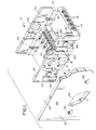
- an electrical connector assembly is shown to include a housing, generally designated 12.
- Connector assembly 10 is of a type shown in U.S. Patent No. 5,125,846 to Sampson et al, dated June 30, 1992, which is assigned to the assignee of the present invention and which is incorporated herein by reference.
- the electrical connector assembly is an input-output connector for coupling a plurality of conductors with an electronic component.
- the connector is designed to connect a plurality of discrete insulated conductor wires to a printed circuit board having circuit traces thereon.
- housing 12 is integrally molded of dielectric material, such as plastic or the like, and includes locating means in the form of a plurality of channels 14 for locating discrete insulated conductor wires.
- the channels are partially closed by retention fingers 16 whereby the conductors or wires are retained in the channels by snapping the conductors past the retention fingers.
- the housing has ledges 18 onto which a printed circuit board is mounted or seated, with locating pegs 20 projecting through mounting holes in the board.
- the circuit board is retained on ledges 18 by hooked snap latches 22.
- a plurality of terminals 24 interconnect the discrete insulated conductor wires with the printed circuit board.
- the terminals include insulation-displacement sections (not shown) for termination to the insulated conductor wires, and the terminals are surface engageable with circuit traces on the underside of the printed circuit board by the sections of the terminals shown in Figure 1.
- Other details of the connector assembly are not relevant to the invention herein, but any further details can be derived from the aforementioned 5,125,846 patent.
- the invention contemplates the provision of complementary interengaging rotary mounting means for mounting connector housing 12 on one side 26 of a panel 28 or other planar mounting substrate.
- the mounting means is responsive to rotation of the housing relative to the panel.
- a boss 30 is molded integrally with and projects outwardly from a side wall 32 of housing 12.
- the boss includes an enlarged head portion 34 which is adapted to be inserted through an aperture 36 in panel 28.
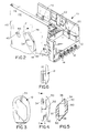
- Enlarged head portion 34 and aperture 36 are substantially identically shaped, with the aperture being slightly larger than the headed portion, so that the headed portion and boss 30 can be inserted into the aperture in the direction of arrows "A".
- enlarged head portion and the aperture are irregularly shaped, sort of in a diamond configuration, so that the head portion has a long dimension as indicated by double-headed arrow "B", and a short dimension as indicated by double-headed arrow "C".
- Boss 30 has a transverse dimension generally equal to the small dimension "C” but smaller than the large dimension "B". Therefore, enlarged head portion 34 defines ledges 38 on the back side thereof which project outwardly of the boss.
- the invention also contemplates the provision of complementary interengaging detent latch means for automatically holding or locking housing 12 in its second or final mounting position shown in Figure 2, in response to rotation of the housing thereto from its initial or insertion position.
- a pair of cantilevered spring beams 42 are molded integrally with connector housing 12 and include detent latch projections 44 projecting outwardly from side wall 32, i.e. projecting toward panel 28.
- the cantilevered spring beams and latch projections provide resilient detent latches of the complementary interengaging detent latch means.
- Panel 28 is provided with a pair of detent recesses in the form of holes 46 which are slightly larger than detent projections 44. Both projections 44 and holes 46 are circular in shape as shown in the preferred embodiment in the drawings.
- detent recesses 46 are located so that resilient detent latch projections 44 snap into the recesses when connector housing is rotated to its final mounting position. This is shown in Figure 2.
- the complementary interengaging detent latch means oppose rotational forces which may be applied to connector housing 12, such as during termination to its discrete conductor wires or mating with any other complementary mating electrical component.
- the invention also contemplates a feature wherein the connector housing is drawn tightly against side 26 of panel 28 in response to rotation of the housing to its final mounting position.
- wedge means are provided on the underside of enlarged head portion 34 for drawing the housing against side 26 of panel 28 in response to rotation of the housing to its final mounting position.
- the wedge means are provided by at least a pair of tapered ribs 50 on the back side of enlarged head portion 34 outside boss 30.
- the ribs are wider near the boss and become narrower toward the periphery of the enlarged head portion, as can be seen best in Figure 5. More significantly, the ribs have a maximum thickness near the boss and a minimum thickness near the periphery of the enlarged head portion, as can be seen best in Figure 4. Therefore, as the connector housing is rotated relative to panel 28, the thinnest outer points of ribs 50 initially will engage the edges of aperture 36 in the panel. Continued rotation causes the ribs to move further against the outside 40 of the panel to draw the housing tighter against the inside 26 of the panel.
- ribs 50 can be dimensioned so that they are deformable to ensure a very tight fit between the connector housing and the panel in a direction generally perpendicular to the panel.
Landscapes
- Details Of Connecting Devices For Male And Female Coupling (AREA)
- Connector Housings Or Holding Contact Members (AREA)
Description
Claims (3)
- A system for mounting an electrical connector (10) to one (26) side of a panel (23), comprising:characterized in that said mounting means (50) are wedge means, comprising a tapered rib (50) having a maximum thickness nearer the boss (30) and a minimum thickness nearer the periphery of the enlarged head portion (34).a connector (10) including a housing (12) having a mounting face (34) with a mounting boss (30) projecting therefrom, the mounting boss including an enlarged head portion (34); anda panel (28) including an aperture (36) shaped for receiving the enlarged head portion therethrough such that the boss is rotatable in the aperture from a first insertion position and a second mounted position of the housing whereat the enlarged head portion overlaps the opposite side (40) of the panel (28); andmounting means (50) on the underside (38) of the enlarged head portion (34) of the boss (30) for engaging the opposite side (40) of the panel (23) and drawing the housing (12) against the one side (23) of the panel in response to said rotation of the hcusing from the first position to the second position,
- The system of claim 1, wherein said tapered rib (50) is of deformable plastic material whereby the rib can be deformed when the housing (12) is rotated to the second position.
- A system for mounting an electrical connector (10) to one side (26) of a panel (12), comprising:a connector (10) including a housing (12) having a mounting face (32) with a mounting boss (30) projecting therefrom, the mounting boss including an enlarged head portion (34);a panel (28) including an aperture (36) shaped for receiving the enlarged head portion therethrough such that the boss is rotatable in the aperture from a first insertion position and a second mounted position of the housing whereat the enlarged head portion overlaps the opposite side (40) of the panel ; andmounting means (50) on the underside (38) of the enlarged head portion (34) of the boss (30) for engaging the opposite side (40) of the panel (28) and drawing the housing (12) against the one side (26) of the panel in response to said rotation of the housing from the first position to the second position, characterized in that said mounting means (50) are wedge means (50) being of deformable plastic material which can deform when the housing is rotated to the second position.
Applications Claiming Priority (2)
| Application Number | Priority Date | Filing Date | Title |
|---|---|---|---|
| US62519 | 1993-05-14 | ||
| US08/062,519 US5338226A (en) | 1993-05-14 | 1993-05-14 | Panel mounting system for electrical connectors |
Publications (3)
| Publication Number | Publication Date |
|---|---|
| EP0624932A2 EP0624932A2 (en) | 1994-11-17 |
| EP0624932A3 EP0624932A3 (en) | 1996-01-10 |
| EP0624932B1 true EP0624932B1 (en) | 1999-03-10 |
Family
ID=22043007
Family Applications (1)
| Application Number | Title | Priority Date | Filing Date |
|---|---|---|---|
| EP94107121A Expired - Lifetime EP0624932B1 (en) | 1993-05-14 | 1994-05-06 | Panel mounting system for electrical connectors |
Country Status (4)
| Country | Link |
|---|---|
| US (1) | US5338226A (en) |
| EP (1) | EP0624932B1 (en) |
| JP (1) | JP2617168B2 (en) |
| DE (1) | DE69416889T2 (en) |
Families Citing this family (17)
| Publication number | Priority date | Publication date | Assignee | Title |
|---|---|---|---|---|
| DE3808402A1 (en) * | 1988-03-12 | 1989-09-21 | Opel Adam Ag | DIFFERENTIAL GEARBOXES FOR THE DRIVE AXLES OF MOTOR VEHICLES |
| JP3242820B2 (en) * | 1995-09-28 | 2001-12-25 | 矢崎総業株式会社 | Movable connector positioning mechanism |
| JPH0997652A (en) * | 1995-09-29 | 1997-04-08 | Yazaki Corp | Movable connector rotation prevention structure |
| US5888093A (en) * | 1996-05-02 | 1999-03-30 | Molex Incorporated | Floating panel mounting system for electrical connectors |
| US5772469A (en) * | 1996-05-02 | 1998-06-30 | Molex Incorporated | Floating panel mounting system for electrical connectors |
| DE19720725C2 (en) * | 1997-05-16 | 2001-04-19 | Siedle & Soehne S | Door system |
| DE19735833A1 (en) * | 1997-08-18 | 1999-02-25 | Porsche Ag | Fixing element for plug connector or line |
| KR100271413B1 (en) * | 1998-03-12 | 2000-11-15 | 최만형 | The case of inducing light for emergency exit |
| US6312285B1 (en) | 1999-02-25 | 2001-11-06 | Molex Incorporated | Panel mounting system for electrical connectors |
| US6095854A (en) * | 1999-04-12 | 2000-08-01 | Molex Incorporated | Panel mounting system for electrical connectors |
| NZ514500A (en) | 2001-10-11 | 2004-06-25 | Deep Video Imaging Ltd | A multiplane visual display unit with a transparent emissive layer disposed between two display planes |
| US7431610B2 (en) * | 2005-01-21 | 2008-10-07 | Leviton Manufacturing Co., Inc. | Cable slack manager system and method |
| US7090533B1 (en) * | 2005-08-25 | 2006-08-15 | Sumitomo Wiring Systems, Ltd. | Twist lock panel-mounted connector |
| DE202006019402U1 (en) | 2006-12-22 | 2008-04-30 | Weidmüller Interface GmbH & Co. KG | Connector system for wall mounting |
| CN104635983B (en) * | 2008-07-31 | 2018-01-30 | 郡是株式会社 | Soft-touch control |
| US20130240681A1 (en) * | 2012-03-16 | 2013-09-19 | Enduro Composites, Inc. | Conduit tray, cam connector and associated methods |
| US10593168B2 (en) | 2017-03-03 | 2020-03-17 | William A. Brown | Electric fence insulator with a light |
Family Cites Families (15)
| Publication number | Priority date | Publication date | Assignee | Title |
|---|---|---|---|---|
| US3180606A (en) * | 1962-12-04 | 1965-04-27 | Byron J Sabin | Wedge locking bracket |
| US3179367A (en) * | 1963-04-11 | 1965-04-20 | Illinois Tool Works | Plastic quarter turn shelf support |
| US3403370A (en) * | 1965-10-15 | 1968-09-24 | Wagner Electric Corp | Mechanically based rear loading panel lamp |
| US3447016A (en) * | 1966-11-02 | 1969-05-27 | Wagner Electric Corp | Rear loading panel lamps and a method of basing the same |
| US3523267A (en) * | 1968-01-24 | 1970-08-04 | Amp Inc | Disengageable electrical connector |
| US3559152A (en) * | 1968-06-07 | 1971-01-26 | Gen Motors Corp | Lamp socket and panel assembly |
| US4427255A (en) * | 1979-11-14 | 1984-01-24 | General Electric Company | Plastic based glass halogen lamp |
| JPS6039531Y2 (en) * | 1981-10-22 | 1985-11-27 | シャープ株式会社 | Attachment device for objects to be attached such as stopper pins |
| JPS5936109U (en) * | 1982-08-30 | 1984-03-07 | 松下電器産業株式会社 | Mounting device for lamp holders etc. |
| JPS60141019U (en) * | 1984-02-29 | 1985-09-18 | 日本精機株式会社 | Lamp socket retainer |
| FR2567596B1 (en) * | 1984-07-16 | 1986-12-26 | Peugeot | CLIP FOR JOINING PARTS, SUCH AS PANELS |
| JPH0263328U (en) * | 1988-11-01 | 1990-05-11 | ||
| JPH02113282U (en) * | 1989-02-28 | 1990-09-11 | ||
| AU639093B2 (en) * | 1990-05-14 | 1993-07-15 | Toyoda Gosei Co. Ltd. | Securing device for manipulated component |
| US5125846A (en) * | 1991-07-25 | 1992-06-30 | Molex Incorporated | Input-output electrical connector |
-
1993
- 1993-05-14 US US08/062,519 patent/US5338226A/en not_active Expired - Lifetime
-
1994
- 1994-05-06 DE DE69416889T patent/DE69416889T2/en not_active Expired - Fee Related
- 1994-05-06 EP EP94107121A patent/EP0624932B1/en not_active Expired - Lifetime
- 1994-05-11 JP JP6121880A patent/JP2617168B2/en not_active Expired - Lifetime
Also Published As
| Publication number | Publication date |
|---|---|
| DE69416889D1 (en) | 1999-04-15 |
| EP0624932A3 (en) | 1996-01-10 |
| JP2617168B2 (en) | 1997-06-04 |
| DE69416889T2 (en) | 1999-10-21 |
| EP0624932A2 (en) | 1994-11-17 |
| JPH076827A (en) | 1995-01-10 |
| US5338226A (en) | 1994-08-16 |
Similar Documents
| Publication | Publication Date | Title |
|---|---|---|
| US5338226A (en) | Panel mounting system for electrical connectors | |
| US3533045A (en) | Supporting and keying means for printed circuit boards or the like | |
| JP2654436B2 (en) | Electrical connector | |
| US5184961A (en) | Modular connector frame | |
| JPH0244469Y2 (en) | ||
| US4376565A (en) | Electrical connector keying means | |
| JP3995174B2 (en) | Electrical connector | |
| CN1130799C (en) | Connector for flat flexible circuitry | |
| US5888093A (en) | Floating panel mounting system for electrical connectors | |
| US4934943A (en) | Automated connector alignment assembly for connection of printed circuit boards | |
| US5277627A (en) | Electrical connector for IC card | |
| JPH0411346Y2 (en) | ||
| US4479691A (en) | Connector assembly | |
| US6450834B1 (en) | Panel mounting system for electrical connectors | |
| US5273462A (en) | Connector keying system | |
| EP0510229B1 (en) | An electrical connector with positive latch | |
| JPH07142128A (en) | Card edge connector | |
| US4971571A (en) | Self-locking pin field connector | |
| US6210217B1 (en) | Electrical connector system having a connector mounted on a conductive panel | |
| US5772469A (en) | Floating panel mounting system for electrical connectors | |
| US6135816A (en) | Electrical connector having an improved construction for fixing shield plates to a receptacle connector | |
| CN1568563A (en) | Keyed connector assembly for flat flexible circuitry | |
| US6302744B1 (en) | Connector system with polarizing key mechanism | |
| US4113337A (en) | Connector constructions and mounting means and hoods therefor | |
| JPH04218281A (en) | Electric connector |
Legal Events
| Date | Code | Title | Description |
|---|---|---|---|
| PUAI | Public reference made under article 153(3) epc to a published international application that has entered the european phase |
Free format text: ORIGINAL CODE: 0009012 |
|
| AK | Designated contracting states |
Kind code of ref document: A2 Designated state(s): DE FR GB IT |
|
| PUAL | Search report despatched |
Free format text: ORIGINAL CODE: 0009013 |
|
| AK | Designated contracting states |
Kind code of ref document: A3 Designated state(s): DE FR GB IT |
|
| 17P | Request for examination filed |
Effective date: 19960704 |
|
| 17Q | First examination report despatched |
Effective date: 19970707 |
|
| GRAG | Despatch of communication of intention to grant |
Free format text: ORIGINAL CODE: EPIDOS AGRA |
|
| GRAG | Despatch of communication of intention to grant |
Free format text: ORIGINAL CODE: EPIDOS AGRA |
|
| GRAH | Despatch of communication of intention to grant a patent |
Free format text: ORIGINAL CODE: EPIDOS IGRA |
|
| GRAH | Despatch of communication of intention to grant a patent |
Free format text: ORIGINAL CODE: EPIDOS IGRA |
|
| GRAA | (expected) grant |
Free format text: ORIGINAL CODE: 0009210 |
|
| AK | Designated contracting states |
Kind code of ref document: B1 Designated state(s): DE FR GB IT |
|
| REF | Corresponds to: |
Ref document number: 69416889 Country of ref document: DE Date of ref document: 19990415 |
|
| ET | Fr: translation filed | ||
| PLBE | No opposition filed within time limit |
Free format text: ORIGINAL CODE: 0009261 |
|
| STAA | Information on the status of an ep patent application or granted ep patent |
Free format text: STATUS: NO OPPOSITION FILED WITHIN TIME LIMIT |
|
| 26N | No opposition filed | ||
| REG | Reference to a national code |
Ref country code: GB Ref legal event code: IF02 |
|
| PGFP | Annual fee paid to national office [announced via postgrant information from national office to epo] |
Ref country code: GB Payment date: 20030401 Year of fee payment: 10 |
|
| PGFP | Annual fee paid to national office [announced via postgrant information from national office to epo] |
Ref country code: FR Payment date: 20030505 Year of fee payment: 10 |
|
| PGFP | Annual fee paid to national office [announced via postgrant information from national office to epo] |
Ref country code: DE Payment date: 20030530 Year of fee payment: 10 |
|
| PG25 | Lapsed in a contracting state [announced via postgrant information from national office to epo] |
Ref country code: GB Free format text: LAPSE BECAUSE OF NON-PAYMENT OF DUE FEES Effective date: 20040506 |
|
| PG25 | Lapsed in a contracting state [announced via postgrant information from national office to epo] |
Ref country code: DE Free format text: LAPSE BECAUSE OF NON-PAYMENT OF DUE FEES Effective date: 20041201 |
|
| GBPC | Gb: european patent ceased through non-payment of renewal fee |
Effective date: 20040506 |
|
| PG25 | Lapsed in a contracting state [announced via postgrant information from national office to epo] |
Ref country code: FR Free format text: LAPSE BECAUSE OF NON-PAYMENT OF DUE FEES Effective date: 20050131 |
|
| REG | Reference to a national code |
Ref country code: FR Ref legal event code: ST |
|
| PG25 | Lapsed in a contracting state [announced via postgrant information from national office to epo] |
Ref country code: IT Free format text: LAPSE BECAUSE OF NON-PAYMENT OF DUE FEES Effective date: 20050506 |