EP0624846A2 - Bussteuereinrichtung - Google Patents
Bussteuereinrichtung Download PDFInfo
- Publication number
- EP0624846A2 EP0624846A2 EP94303326A EP94303326A EP0624846A2 EP 0624846 A2 EP0624846 A2 EP 0624846A2 EP 94303326 A EP94303326 A EP 94303326A EP 94303326 A EP94303326 A EP 94303326A EP 0624846 A2 EP0624846 A2 EP 0624846A2
- Authority
- EP
- European Patent Office
- Prior art keywords
- bus
- data
- peripheral equipment
- address
- cpu
- Prior art date
- Legal status (The legal status is an assumption and is not a legal conclusion. Google has not performed a legal analysis and makes no representation as to the accuracy of the status listed.)
- Granted
Links
Images


Classifications
-
- G—PHYSICS
- G06—COMPUTING; CALCULATING OR COUNTING
- G06F—ELECTRIC DIGITAL DATA PROCESSING
- G06F13/00—Interconnection of, or transfer of information or other signals between, memories, input/output devices or central processing units
- G06F13/38—Information transfer, e.g. on bus
- G06F13/40—Bus structure
- G06F13/4004—Coupling between buses
- G06F13/4009—Coupling between buses with data restructuring
- G06F13/4018—Coupling between buses with data restructuring with data-width conversion
-
- G—PHYSICS
- G06—COMPUTING; CALCULATING OR COUNTING
- G06F—ELECTRIC DIGITAL DATA PROCESSING
- G06F13/00—Interconnection of, or transfer of information or other signals between, memories, input/output devices or central processing units
- G06F13/38—Information transfer, e.g. on bus
- G06F13/40—Bus structure
- G06F13/4004—Coupling between buses
- G06F13/4027—Coupling between buses using bus bridges
- G06F13/405—Coupling between buses using bus bridges where the bridge performs a synchronising function
- G06F13/4054—Coupling between buses using bus bridges where the bridge performs a synchronising function where the function is bus cycle extension, e.g. to meet the timing requirements of the target bus
-
- G—PHYSICS
- G06—COMPUTING; CALCULATING OR COUNTING
- G06F—ELECTRIC DIGITAL DATA PROCESSING
- G06F13/00—Interconnection of, or transfer of information or other signals between, memories, input/output devices or central processing units
- G06F13/38—Information transfer, e.g. on bus
- G06F13/42—Bus transfer protocol, e.g. handshake; Synchronisation
- G06F13/4204—Bus transfer protocol, e.g. handshake; Synchronisation on a parallel bus
- G06F13/4234—Bus transfer protocol, e.g. handshake; Synchronisation on a parallel bus being a memory bus
- G06F13/4243—Bus transfer protocol, e.g. handshake; Synchronisation on a parallel bus being a memory bus with synchronous protocol
Definitions
- This invention relates to a bus control apparatus suitable for use with, for example, a computer.
- a conventional computer may include a peripheral equipment such as, for example, an interface board which operates at a lower speed than the bus accessing speed of a CPU (central processing unit) of the computer.
- a peripheral equipment such as, for example, an interface board which operates at a lower speed than the bus accessing speed of a CPU (central processing unit) of the computer.
- the speed of the bus accessing by the CPU may be decreased in accordance with the bus accessing timing of the peripheral equipment; however, the processing speed of the entire apparatus is reduced as a result. Therefore, a so-called wait controller or a like apparatus may be provided in order to adjust the timing at which a read signal or a write signal developed from the CPU is to be supplied to the peripheral equipment.
- a conventional computer may include peripheral equipment having a bus width different from that of the CPU, in particular, where, for example, the peripheral equipment uses a bus width of 8 bits while the CPU uses a bus width of 32 bits.
- hardware apparatus for exclusive use for packing and unpacking data may be provided and data of 32 bits outputted from the CPU are divided (unpacked) into four groups of data of 8 bits to be supplied to the peripheral equipment whereas data of 8 bits outputted from the peripheral equipment are read-in in groups of four, to produce (pack) data of 32 bits to be supplied to the CPU.
- peripheral equipment continue to output data for a while even after reading of data of the CPU from the peripheral equipment comes to an end, that is, have long floating times. Further, some other peripheral equipment are required to hold data on a data bus for a while even after outputting of a data write signal from the CPU to write data into the peripheral apparatus comes to an end, that is, have a long hold time.
- the hardware apparatus for packing and unpacking data described above requires, similarly to a wait controller, individual designing of, for example, packing-unpacking trigger generation logic in accordance with the peripheral equipment to be connected to the computer, which again makes it expensive.
- peripheral equipment of a bus width of 8 bits is employed for a CPU of another bus width of 32 bits as described above
- the peripheral equipment is, for example, a memory
- the address into which data should be written must be incremented one by one four times
- the peripheral equipment is an apparatus of the type which has a buffer of a so-called FIFO (first-in first-out) type and for which reading and writing of data are performed at a fixed address
- the peripheral equipment must be constructed so that the four data of 8 bits are written into the same fixed address.
- addressing type whether, when data are written into or read out from the peripheral equipment having a bus width different from that of a CPU, the address is incremented or fixed as described above is referred to as addressing type.
- the hardware apparatus described above is not constructed such that the address of a peripheral equipment into or from which data are to be written or read out is designated taking the addressing type of the peripheral equipment into consideration.
- an application program must be designed and programmed taking the addressing type of the peripheral equipment into consideration, which is cumbersome.
- a bus control apparatus for interconnecting a plurality of bus lines, comprising: a main bus to which a central processing unit is connected; a sub bus to which a peripheral equipment is connected; storage means for storing an operation timing of said peripheral equipment; and control means for controlling an access timing between said central processing unit and said peripheral equipment in accordance with the operation timing of said peripheral equipment stored in said storage means.
- the invention also provides a bus control apparatus for interconnecting a plurality of bus lines, comprising: a main bus to which a central processing unit is connected; a sub bus to which a peripheral equipment is connected; storage means for storing a bus width and an addressing type of said peripheral equipment; data latch means for latching data outputted from said central processing unit or said peripheral equipment; address latch means for latching an address outputted from said central processing unit to said peripheral equipment; and control means for controlling packing/unpacking of data latched in said data latch means in accordance with the bus width of said peripheral equipment stored in said storage means and controlling the address latched in said address latch means in accordance with the addressing type of said peripheral equipment stored in said storage means.
- the access timing between the central processing unit and the peripheral equipment is controlled by the control means in accordance with the operation timing of the peripheral equipment stored in the storage means. Accordingly, a special hardware apparatus such as, for example, a wait controller for adjusting the accessing timing between the central processing unit and the peripheral equipment need not be provided for each item of peripheral equipment which may be connected to the main bus or the sub bus. Consequently, the access timing between the central processing unit and the peripheral equipment can be controlled without increasing the size and the cost of the entire system.
- a special hardware apparatus such as, for example, a wait controller for adjusting the accessing timing between the central processing unit and the peripheral equipment need not be provided for each item of peripheral equipment which may be connected to the main bus or the sub bus. Consequently, the access timing between the central processing unit and the peripheral equipment can be controlled without increasing the size and the cost of the entire system.
- the operation timing of the peripheral equipment stored in the storage means is re-writable so that, even if the specifications of the peripheral equipment are modified or new peripheral equipment is added, it is unlikely that it will not be possible to use the apparatus.
- the storage means may store at least a hold time or a recovery time of the peripheral equipment.
- the timing can be controlled in accordance with the hold time or the recovery time.
- the main bus has a bus width greater than the bus width of the sub bus, and more preferably, the bus width of the main bus is equal to an integral number of times the bus width of the sub bus.
- data outputted from the central processing unit or the peripheral equipment are latched by the data latch means, and an address outputted from the central processing unit to the peripheral equipment is latched by the address latch means.
- Packing/unpacking of the data latched in the data latch means is controlled in accordance with the bus width of the peripheral equipment stored in the storage means while the address latched in the address latch means is controlled in accordance with the addressing type of the peripheral equipment stored in the storage means. Accordingly, an application program can be designed without taking packing/unpacking of data and the addressing type into consideration, and consequently, an application program of high universality in use can be provided.
- the bus width and the addressing type of the peripheral equipment stored in the storage means are re-writable so that, even if the specifications of the peripheral equipment are modified or a new peripheral equipment is added, it is unlikely that it will be impossible to use the apparatus.
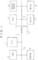
- the computer shown include a CPU 1 which may be, for example, a 32-bit CPU and executes predetermined processes in accordance with a system program stored in a ROM (read only memory) 5 and/or an application program stored in a RAM (random access memory) 2.
- the RAM 2 is, for example, a high speed DRAM (dynamic RAM) of a 32-bit width and temporarily stores an application program or data necessary for operation of the system.
- a device 3 is, for example, a high speed device of a 32-bit width and performs predetermined processing such as sound processing or image processing.
- the CPU 1, the RAM 2 and the device 3 are connected to a main bus 9 in the form of a 32-bit high speed bus, and data of 32 bits are communicated at a high speed between the CPU 1 and the RAM 2 or the device 3 by way of the main bus 9.
- the ROM 5 is, for example, a ROM of an 8-bit width and stores a system program stored in advance therein.
- a backup memory 6 is, for example, a memory of a 16-bit width and stores data as backup data.
- a device 7 is, for example, a device of an 8-bit width and executes predetermined processing such as sound processing or image processing.
- Another device 8 is, for example, an input/output interface of a 16-bit width.
- the ROM 5, the memory 6 and the devices 7 and 8 operate at a operation speed lower than that of the CPU 1 and are connected to a sub bus 10 as a general purpose bus of, for example, 16 bits. It is to be noted, however, that the ROM 5 and the device 7 of an 8-bit width are connected to the lower 8 bits of the sub bus 10 of 16 bits.
- main bus 9 and the sub bus 10 are each constituted from a data bus, an address bus and a control bus.
- a gateway 4 is connected between the main bus 9 and the sub bus 10 and controls communications of data between the CPU 1 and the ROM 5, the memory 6 or the device 7 or 8.
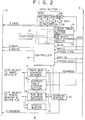
- the gateway 4 includes, for example, a data buffer 11, four multiplexers (MUX) 12a to 12d, a timing table storage section 13, a bus width storage section 14, a counter 15, a controller 16, a main address decoder 17, an address table storage section 18, a sub bus address decoder 19, a status buffer 20, and an address buffer 21.
- MUX multiplexers
- each broken line in FIG. 2 denotes a control signal line.
- the data buffer 11 is controlled by the controller 16 such that it latches data of 32 bits supplied thereto from the CPU 1 by way of the main bus 9 and outputs four data of 8 bits from the uppermost bit of the 32-bit data to the multiplexers 12a to 12d, respectively. Meanwhile, the data buffer 11 latches data from the multiplexers 12a to 12d of 8 bits and outputs them as 32-bit data to the main bus 9.
- the multiplexers 12a to 12d constructed with an 8-bit width are controlled by the controller 16 such that they latch four data of 8 bits from the data buffer 11 and output them as two data of 16 bits or four data of 8 bits to the 10. Meanwhile, the multiplexers 12a to 12d latch two data of 16 bits or four data of 8 bits from the sub bus 10 and outputs them as data of 32 bits to the data buffer 11.
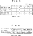
- the timing table storage section 13 stores in advance therein such a timing table as shown in FIG. 3 in which, for example, read delay times, write delay times, hold times, floating times and recovery times of the ROM 5, the memory 6 and the devices 7 and 8 connected to the sub bus 10 are described.
- the read delay time or the write delay time signifies the access time when data are read or written
- the hold time signifies the time for which data must be held on a bus after outputting of a write signal comes to an end.
- the floating time signifies the time for which data must be held on a bus even after reading of data comes to an end
- the recovery time signifies the time interval necessary when a same peripheral equipment is to be connected and accessed (the interval of time which must be provided before a next access after a first access comes to an end).
- the bus width table storage section 14 stores in advance such a bus width table as illustrated in FIG. 4 in which the data lengths (hereinafter referred to as bus widths) handled by the ROM 5, the memory 6, and the devices 7 and 8 connected to the sub bus 10 and the addressing types of them are described.
- any peripheral equipment whose addressing type is fixed in the present embodiment, the devices 7 and 8) has a data buffer of, for example, the FIFO type and requires designation of a predetermined same address (fixed address) upon reading or writing of data divided into a plurality of sets by unpacking.
- any other peripheral equipment whose addressing type is variable in the present embodiment, the ROM 5 and the memory 6) requires, upon reading or writing of data divided into a plurality of sets by unpacking, incrementing or decrementing of the address to designate a new address for reading or writing of data of a next data set after reading or writing of data of one of the data sets.
- the counter 15 counts a system clock (System Clock) supplied thereto from a clock generator not shown by way of the main bus 9 and the controller 16.
- System Clock System Clock
- the controller 16 varies the timing of a read (Read) signal or a write (Write) signal supplied thereto from the CPU 1 by way of the main bus 9 in accordance with the timing table (FIG. 3) stored in the timing table storage section 13 and outputs a resulted signal as an SRead signal or an SWrite signal to the sub bus 10. Further, the controller 16 outputs a DataOK signal, which will be hereinafter described, at a predetermined timing in accordance with the timing table (FIG. 3) stored in the timing table storage section 13.
- the controller 16 controls the data buffer 11 in accordance with a bus width described in the bus width table (FIG. 4) stored in the bus width table storage section 14 and an AccessType (length of data handled by the CPU 1) supplied thereto from the CPU 1 by way of the main bus 9 to pack or unpack data. Meanwhile, the controller 16 controls the address buffer 21 in accordance with an addressing type described in the bus width table (FIG. 4) stored in the bus width table storage section 14.
- the main bus address decoder 17 decodes an address (Address) outputted from the CPU 1 by way of the main bus 9 and compares a result of such decoding with an address decode table stored in the address table storage section 18. The main bus address decoder 17 then determines from a result of the comparison whether the peripheral equipment the CPU 1 tries to access is the RAM 2 or the device 3 connected to the main bus 9, and if it determines that the peripheral equipment is the RAM 2 or the device 3, it outputs a chip select signal to the RAM 2 or the device 3 by way of the main bus 9.
- the address table storage section 18 stores in advance the address decode table in which results of decoding of addresses allocated to the RAM 2, the device 3, the ROM 5, the memory 6 and the devices 7 and 8 are described.
- the sub bus address decoder 19 decodes an address outputted from the CPU 1 by way of the main bus 9 and the address buffer 21 and compares a result of such decoding with the results of decoding of the addresses described in the address decode table of the address table storage section 18 and allocated to the RAM 2, the device 3, the ROM 5, the memory 6, and the devices 7 and 8.
- the sub bus address decoder 19 determines from a result of the comparison whether or not the peripheral equipment the CPU 1 tries to access is the ROM 5, the memory 6, or the device 7 or 8 connected to the sub bus 10, and outputs, when it determines that the peripheral equipment is one of the peripheral equipment connected to the sub bus 10 (that is, one of the ROM 5, the memory 6, and the devices 7 and 8), a chip select signal to the peripheral equipment by way of the sub bus 10.
- the status buffer 20 stores the peripheral equipment to which one of the main bus address decoder 17 and the sub bus address decoder 19 has outputted a chip select signal last, that is, that one of the peripheral equipment which has been accessed last by the CPU 1 (a result of decoding of the address allocated to the peripheral apparatus). Further, when the stored value of the status buffer 20 is the same as that one of the peripheral equipment to which the sub bus address decoder 19 has outputted the chip select signal, that is, when accessing to an arbitrary one of the peripheral equipment connected to the sub bus 10 has occurred successively, the status buffer 20 outputs a control signal to the controller 16 to execute recovery processing which will be hereinafter described.
- the address buffer 21 latches an address supplied thereto from the CPU 1 by way of the main bus 9. The address buffer 21 then holds the thus latched address as it is or increments (or decrements) the latched address by one at a predetermined timing.
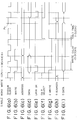
- the address (Address) ((c) of FIG. 5) allocated to the device 7 is outputted from the CPU 1 by way of the main bus 9 so that it is latched by the address buffer 21 and inputted to the main bus address decoder 17.
- the address latched by the address buffer 21 is outputted as a signal SAddress ((h) of FIG. 5) to the sub bus 10 and outputted also to the sub bus address decoder 19.
- the main bus address decoder 17 and the sub bus address decoder 19 decode the address received from the CPU 1, and results of the decoding are compared with the address decode table stored in the address table storage section 18.
- the address allocated to the device 7 is held outputted from the CPU 1 as described above, it is detected by the sub bus address decoder 19 that the peripheral equipment the CPU 1 tries to access is the device 7, and a chip select signal (ChipSelect) ((f) of FIG. 5) is outputted from the CPU 1 to the device 7 by way of the sub bus 10.
- ChipSelect ChipSelect
- the result of decoding of the sub bus address decoder 19 is stored into the status buffer 20 and then outputted from the status buffer 20 to the controller 16. Consequently, it is recognized by the controller 16 that the object for accessing of the CPU 1 is the device 7.
- a read signal (Read) ((b) of FIG. 5) and an accessing type signal (AccessType) indicative of byte accessing are supplied from the CPU 1 to the controller 16 by way of the main bus 9.
- Read read signal
- AccessType accessing type signal
- the controller 16 When the controller 16 receives the read signal (Read) from the CPU 1, it outputs a read signal (SRead) ((g) of FIG. 5) to the sub bus 10.
- the device 7 has a read delay time of 2 clocks as seen from the timing table of FIG. 3.
- a time for two clocks is required before the device 7 outputs data to the sub bus 10 after a chip select signal and a read signal (SRead) are supplied thereto.
- the controller 16 After the controller 16 outputs the read signal (SRead) to the sub bus 10, it resets the counter 15 and causes the counter 15 to start counting beginning with 0 at the timing of a system clock ((a) of FIG. 5).
- controller 16 refers to the read delay time of the device 7 described in the timing table (FIG. 3) of the timing table storage section 13 and places a waiting time until the count value of the counter 15 becomes equal to the read delay time of the device 7.
- the waiting time of 2 clocks is placed after the read signal (SRead) is outputted.
- one-byte data (SData) ((i) of FIG. 5) are outputted from the device 7 to the lower 8 bits of the sub bus 10 of 16 bits, and a control signal based on the 8-bit (one-byte) signal AccessType representative of an accessing type from the CPU 1 is outputted from the controller 16 to the multiplexer 12d and the data buffer 11 so that data of the lower 8 bits of the sub bus 10 may be latched.
- the one-byte data (SData) from the device 7 are latched at the lower 8 bits of the data buffer 11 by way of the multiplexer 12d.
- a DataOk signal ((e) of FIG. 5) indicating that it is enabled to output data from the device 7 to the main bus 9 is supplied from the controller 16 to the CPU 1 by way of the main bus 9, and the read signal (SRead) ((g) of FIG. 5) which has been outputted from the controller 16 to the sub bus 10 is stopped.
- the controller 16 resets the counter 15 so that the counter 15 starts counting beginning with 0 at the timing of a system clock ((a) of FIG. 5).
- the data latched by the data buffer 11 are outputted to the main bus 9 ((d) of FIG. 5) so that they are read in by the CPU 1.
- the CPU 1 then stops outputting of the read signal (Read) ((b) of FIG. 5) and the address (Address) ((c) of FIG. 5) to the main bus 9.
- the controller 16 causes the sub bus address decoder 19 to stop outputting of the chip select signal (ChipSelect) ((f) of FIG. 5) to the device 7.
- the controller 16 causes, after the floating time of the device 7 elapses after the time at which the data from the device 7 are latched by the data buffer 11 (reading of the data comes to an end) and outputting of the data (SData) ((i) of FIG. 5) from the device 7 to the sub bus 10 is stopped, that is, the count value of the counter 15 becomes equal to the floating time of the device 7 described in the timing table (FIG. 3), the address buffer 21 to stop outputting of the address (SAddress) ((h) of FIG. 5) to the sub bus 10.
- the CPU 1 recognizes, at the point of time when outputting of the address (Address) ((c) of FIG. 5) to the main bus 9 is stopped as described above, that accessing to the device 7 has been completed (actually such accessing has been completed with the CPU 1).
- the gateway 4 is constructed so that, in this instance, the data outputted from the CPU 1 are latched by the data buffer 11 and a signal DataOk indicating that writing of data into the memory 6 has been completed is outputted from the controller 16 to the CPU 1.
- the CPU 1 recognizes that writing of data into the memory 6 has been completed (although such writing has not been completed as yet). Accordingly, the main bus 9 is released immediately, and the CPU 1 can thereafter execute any processing except the process of accessing to any of the peripheral equipment connected to the sub bus 10.
- a write signal (SWrite), a chip select signal or an address (SAddress) is outputted from the controller 16, the sub bus address decoder 19 or the address buffer 21 to the memory 6 by way of the sub bus 10. Then, the data from the CPU 1 latched by the data buffer 11 are outputted to and written into the memory 6 by way of the sub bus 10.
- the CPU 1 can execute writing processing of data into the memory without waiting the lapse of the floating time of the device 7 after the point of time at which data from the device 7 are latched by the data buffer 11 (reading of data comes to an end). Consequently, the processing speed of the entire apparatus can be enhanced.
- writing processing of data into the memory 6 is transferred from the CPU 1 to the gateway 4 and accordingly is thereafter executed by the gateway 4. Accordingly, the CPU 1 can immediately execute any other processing. Consequently, access timings between the CPU 1 and the peripheral equipment need not be considered, which facilitates development of an application program.
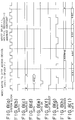
- FIG. 6 illustrates writing processing of data from the CPU 1 into the device 8.
- the address (Address) ((c) of FIG. 6) allocated to the device 8 is first outputted from the CPU 1 by way of the main bus 9.
- the address is latched by the address buffer 21 and inputted to the main bus address decoder 17.
- the address latched by the address buffer 21 is outputted as a signal SAddress ((h) of FIG. 6) to the sub bus 10 and outputted also to the sub bus address decoder 19.
- the address from the CPU 1 is decoded by the main bus address decoder 17 and the sub bus address decoder 19, and results of such decoding are compared with the address decode table stored in the address table storage section 18.
- the address allocated to the device 8 is held outputted from the CPU 1 as described above, it is detected by the sub bus address decoder 19 that the peripheral equipment the CPU 1 tries to access is the device 8, and a chip select signal (ChipSelect) ((f) of FIG. 6) is outputted from the sub bus address decoder 19 to the device 8 by way of the sub bus 10.
- ChipSelect ChipSelect
- the result of decoding of the sub bus address decoder 19 is stored into the status buffer 20 and then outputted from the status buffer 20 to the controller 16. Consequently, the controller 16 recognizes that the object for accessing of the CPU 1 is the device 8.
- a write signal (Write) ((b) of FIG. 6) is supplied to the controller 16 by way of the main bus 9 and data (Data) are supplied to and latched by the data buffer 11.
- the controller 16 supplies a DataOk signal ((e) of FIG. 6) indicating that writing of the data (Data) into the device 8 has been completed (although such writing has not been completed as yet) to the CPU 1 by way of the main bus 9.
- the CPU 1 Upon reception of the DataOk signal, the CPU 1 recognizes that writing of the data (Data) has been completed, and stops outputting of the write signal (Write), the address (Address) and the data (Data), whereafter it executes next processing.
- the controller 16 upon reception of the write signal (Write) from the CPU 1, the controller 16 outputs a write signal (SWrite) ((g) of FIG. 6) to the sub bus 10 and outputs a control signal to the data buffer 11 to output the latched data as a signal SData ((i) of FIG. 6) to the sub bus 10.
- a write signal SWrite
- SData ((i) of FIG. 6)
- the device 8 has a write delay time of 3 clocks as seen from the timing table of FIG. 3.
- the device 8 requires the time for three clocks before data are fetched from the sub bus 10 after a chip select signal and a write signal (SWrite) are supplied thereto.
- SWrite write signal
- the device 8 has a hold time of one clock.
- the data (SData) and the address (SAddress) must necessarily be continued to be supplied to the sub bus 10 before the time at least for one clock elapses after supplying of the write signal (SWrite) is stopped.
- the controller 16 first resets, after it outputs a write signal (SWrite) ((g) of FIG. 6) to the sub bus 10, the counter 15 and then causes the counter 15 to start counting beginning with 0 at the timing of a system clock ((a) of FIG. 6).
- SWrite write signal
- controller 16 refers to the write delay time of the device 8 described in the timing table (FIG. 3) of the timing table storage section 13 and places a waiting time until after the count value of the counter 15 becomes equal to the write delay time of the device 8.
- controller 16 After the controller 16 stops outputting of the write signal (SWrite) ((g) of FIG. 6), it resets the counter 15 and then causes the counter 15 to start counting beginning with 0 at the timing of a system clock ((a) of FIG. 6).
- SWrite write signal
- the controller 16 refers to the hold time of the device 8 described in the timing table (FIG. 3) of the timing table storage section 13 and places a waiting time until after the count value of the counter 15 becomes equal to the hold time of the device 8.
- the accessing timings to the device 8 which has a hold time are controlled in such a manner as described above so that writing of data into the device 8 is assured (data are written accurately into the device 8).
- writing processing of data into the device 8 is transferred from the CPU 1 to the gateway 4 so that the writing processing is thereafter executed by the gateway 4. Accordingly, the CPU 1 can immediately execute any other processing as described above, and consequently, the processing speed of the entire apparatus can be enhanced.
- the gateway 4 executes timing control taking the write delay time (FIG. 3) of the memory 6 into consideration (the hold time (FIG. 3) of the memory 6 is ignored since it is equal to 0).
- the memory 6 has a recovery time of 10 clocks as seen from the timing table of FIG. 3. In particular, when it is tried to successively access the memory 6 twice, second time accessing is not assured before the time for 10 clocks elapses after first time accessing comes to an end.
- the gateway 4 after second time accessing to the memory 6 is started after completion of first time accessing to the memory 6 and a result of decoding of the address allocated to the peripheral equipment to which the sub bus address decoder 19 has outputted a chip select signal is supplied to the status buffer 20, the result of the decoding is compared with a stored value currently stored in the status buffer 20.
- the last result of decoding of the sub bus address decoder 19, that is, the fact that the peripheral equipment which has been accessed last is the memory 6, is stored in the status buffer 20.
- controller 16 executes recovery processing.
- the controller 16 first resets the counter 15 and causes the counter 15 to start counting beginning with 0 at the timing of a system clock.
- the controller 16 refers to the recovery time of the memory 6 described in the timing table (FIG. 3) of the timing table storage section 13, and if the recovery time is longer than 0, the controller 16 places a waiting time until the count value of the counter 15 becomes equal to the recovery time of the memory 6.
- a waiting time (interval) for 10 clocks is placed, and thereafter, second time writing of data into the memory 6 is performed.
- the accessing timing to the memory 6 which has a recovery time is controlled in such a manner as described above, and even if accessing to the memory 6 occurs successively, the operation in such accessing is assured.
- the CPU 1 recognizes that writing of the data into the memory 6 has been completed (although actually the data have been merely latched by the data buffer 11 and writing of the data into the memory 6 is not completed as yet), and the main bus 9 is released. Accordingly, the CPU 1 can execute another processing immediately after completion of the first time accessing to the memory 6 by the gateway 4, and consequently, the processing speed of the entire apparatus can be enhanced.
- timing table (FIG. 3) stored in the timing table storage section 13 can be re-written by the CPU 1 executing a predetermined program. Accordingly, even if the specifications of, for example, any of the ROM 5, the backup memory 6, and the devices 7 and 8 are varied or a new peripheral equipment is added, only it is necessary to re-write the timing table, and such a situation that, for example, the compatibility of application software which has been used till now is lost to disable use of the application software is eliminated.
- an address (Address) ((c) of FIG. 7) of the data to be read out from the ROM 5 is outputted from the CPU 1 by way of the main bus 9.
- the address is latched by the address buffer 21 and inputted to the main bus address decoder 17.
- the address latched by the address buffer 21 is outputted as a signal SAddress ((h) of FIG. 7) to the sub bus 10 and outputted to the sub bus address decoder 19.
- the address from the CPU 1 is decoded by the main bus address decoder 17 and the sub bus address decoder 19, and a result of the decoding is compared with the address decode table stored in the address table storage section 18.
- the address of the ROM 5 is outputted from the CPU 1 as described above, it is detected by the sub bus address decoder 19 that the peripheral equipment the CPU 1 tries to access is the ROM 5, and a chip select signal (ChipSelect) ((f) of FIG. 7) is outputted from the sub bus address decoder 19 to the ROM 5 by way of the sub bus 10.
- ChipSelect ChipSelect
- the result of decoding of the sub bus address decoder 19 is stored into the status buffer 20 and then outputted from the status buffer 20 to the controller 16. Consequently, it is recognized by the controller 16 that the object for accessing of the CPU 1 is the ROM 5.
- a read signal (Read) ((b) of FIG. 7) and an accessing type signal (AccessType) indicating that the length of data to be read out is 32 bits are supplied from the CPU 1 to the controller 16 by way of the main bus 9.
- the controller 16 Upon reception of the read signal (Read) from the CPU 1, the controller 16 outputs a read signal (SRead) ((g) of FIG. 7) to the sub bus 10.
- the ROM 5 has a bus width of 8 bits and a variable addressing type as seen from the bus width table of FIG. 4.
- the processing of reading out data in units of 8 bits as the bus width unit must necessarily be performed four times incrementing (or decrementing) the address.
- the controller 16 executes the following control in accordance with the accessing type signal (AccessType) received from the CPU 1 and the bus width and the addressing type of the ROM 5 described in the bus width table (FIG. 4) of the bus width table storage section 14.
- AccessType accessing type signal
- the controller 16 first causes 8-bit data outputted from the address (SAddress) of the ROM 5 to the sub bus 10 as described above to be latched at the lower 8 bits of the data buffer 11 of 32 bits by way of the multiplexer 12d.
- the controller 16 After the 8-bit data read out from the addresses (SAddress, SAddress+1, SAddress+2 and SAddress+3) of the ROM 5 are latched by the data buffer 11 in such a manner as described above to form data of 32 bits, that is, after four data of 8 bits are packed into data of 32 bits, the controller 16 outputs a signal DataOK ((e) of FIG. 7) to the CPU 1 by way of the main bus 9 and causes the data of 32 bits ((d) of FIG. 7) latched in the data buffer 11 to be outputted to the main bus 9.
- a signal DataOK ((e) of FIG. 7)
- the CPU 1 Upon reception of the signal DataOK, the CPU 1 fetches the data of 32 bits on the main bus 9, thereby completing reading of the data of 32 bits from the ROM 5.
- the bus width table (FIG. 4) stored in the bus width table storage section 14 can be re-written by the CPU 1 executing a predetermined program. Accordingly, if, for example, the ROM 5 is changed from an 8-bit ROM to a 16-bit ROM, it is only necessary to change the bus width of the ROM 5 of the bus width table (FIG. 4) from 8 bits to 16 bits.
- two 16-bit data are read out from the ROM 5, and one of the two data, for example, the data of 16 bits of the lower address, are latched at the lower 16 bits of the data buffer 11 by way of the multiplexers 12c and 12d and the other of the two data, for example, the data of 16 bits of the upper address, are latched at the upper 16 bits of the data buffer 11 by way of the multiplexers 12a and 12b so that the two 16-bit data are packed into 32-bit data.
- an address (Address) ((c) of FIG. 8) of the device 7 into which data are to be written is outputted from the CPU 1 by way of the main bus 9.
- the address is latched by the address buffer 21 and inputted to the main bus address decoder 17.
- the address latched by the address buffer 21 is outputted as a signal SAddress ((h) of FIG. 8) to the sub bus 10, and is outputted to the sub bus address decoder 19.
- the address from the CPU 1 is decoded by the main bus address decoder 17 and the sub bus address decoder 19, and a result of the decoding is compared with the address decode table stored in the address table storage section 18.
- the address of the device 7 is outputted from the CPU 1 as described above, it is detected by the sub bus address decoder 19 that the peripheral equipment the CPU 1 tries to access is the device 7, and a chip select signal (ChipSelect) ((f) of FIG. 8) is outputted from the sub bus address decoder 19 to the device 7 by way of the sub bus 10.
- ChipSelect ChipSelect
- the result of decoding of the sub bus address decoder 19 is stored into the status buffer 20 and outputted from the status buffer 20 to the controller 16. Consequently, it is recognized by the controller 16 that the object for accessing of the CPU 1 is the device 7.
- a write signal (Write) and an accessing type signal (AccessType) indicating that the length of data to be written is 32 bits are supplied from the CPU 1 to the controller 16 by way of the main bus 9, and data (Data) ((d) of FIG. 8) to be written into the device 7 are outputted from the CPU 1 to the main bus 9.
- the controller 16 Upon reception of the write signal (Write) from the CPU 1, the controller 16 causes the data buffer 11 to latch the 32-bit data on the main bus 9 and outputs a write signal (SWrite) ((g) of FIG. 8) to the sub bus 10.
- SWrite write signal
- the controller 16 outputs a signal DataOK to the CPU 1. Consequently, the CPU 1 recognizes that writing of data into the device 7 has been completed (although such writing has not actually been completed as yet), and the main bus 9 is released. Accordingly, since the CPU 1 thereafter can execute any other processing immediately, the processing speed of the entire apparatus can be enhanced.
- the device 7 has a bus width of 8 bits and a fixed addressing type as seen from the bus width table of FIG. 4.
- the accessing type signal (AccessType) it is necessary to divide the 32-bit data equally into four data of 8 bits as a bus width unit of the device 7 and write the four 8-bit data fixing the address.
- the controller 16 executes the following control in accordance with the accessing type signal (AccessType) received from the CPU 1 and a bus width and an addressing type of the device 7 described in the bus width table (FIG. 4) of the bus width table storage section 14.
- AccessType accessing type signal
- controller 16 causes data of 32 bits latched in the data buffer 11 to be read out into the multiplexers 12a to 12d of an 8-bit width to unpack the data into four 8-bit data.
- the controller 16 then causes the data of 8 bits on the LSB (least significant bit) side of the 32-bit data read out by the multiplexer 12d to be outputted to the lower 8 bits of the sub bus 10. Consequently, the data of 8 bits are written into the address (SAddress) of the device 7.
- the controller 16 causes the address buffer 21 to output the data of next upper 8 bits to the 8 bits on the LSB side of the 32-bit data, which have been read out by the multiplexer 12c, while leaving the address buffer 21 to hold the stored address (SAddress), to the lower 8 bits of the sub bus 10. Consequently, the data of 8 bits are written into the address (SAddress) of the device 7.
- the controller 16 causes the multiplexers 12a to 12d to successively turn on and off the write signal (SWrite) to the device 7 as seen from (g) of FIG. 8 in accordance with the timing at which data are read out from the data buffer 11.
- the device 7 has a buffer of, for example, of the FIFO type, and the four data of 8 bits written into the address (SAddress) are successively stacked (loaded) into the buffer and are thereafter processed by predetermined processing by the device 7.
- the data of lower 16 bits of the 32-bit data latched in the data buffer 11 are read out by the multiplexers 12c and 12d and the data of upper 16 bits are read out by the multiplexers 12a and 12b to unpack the 32-bit data into two 16-bit data.
- the gateway 4 first waits that an address is outputted together with a write signal or a read signal from the CPU 1 by way of the main bus 9. Then, after an address is outputted together with a write signal or a read signal from the CPU 1, the control sequence advances to step S2, at which the address from the CPU 1 is outputted to the peripheral equipment and decoding of the address is performed. Then, the gateway 4 outputs a chip select signal to one of the peripheral equipment indicated by a result of the decoding.
- control sequence then advances to step S3, at which it is determined from the result of decoding of the address from the CPU 1 whether or not the peripheral equipment the CPU 1 tries to access is connected to the sub bus 10.
- step S3 When it is determined at step S3 that the peripheral equipment the CPU 1 tries to access is not connected to the sub bus 10, that is, when the peripheral equipment the CPU 1 tries to access is connected to the main bus 9, the recovery processing described above need not be executed, and consequently, the control sequence advances to step S4, at which the status buffer 20 is cleared, whereafter the control sequence advances to step S5.
- step S5 accessing of the CPU 1 to the peripheral equipment connected to the main bus 9 is performed, and after such accessing comes to an end, the control sequence returns to step S1 to repeat the processes beginning with step S1.
- step S3 when it is determined at step S3 that the peripheral equipment the CPU 1 tries to access is connected to the sub bus 10, the control sequence successively advances to steps S6 and S7, at which the timing table and the bus width table are read out from the timing table storage section 13 and the bus width table storage section 14, respectively.
- step S8 it is determined whether or not the accessing type of the CPU 1 and the bus width of the peripheral equipment the CPU 1 tries to access are equal to each other.
- step S10 the control sequence advances to step S10, at which a variable N is set to 1, whereafter the control sequence advances to step S11.
- step S8 when it is determined at step S8 that the accessing type of the CPU 1 and the bus width of the peripheral equipment the CPU 1 tries to access are not equal to each other, the control sequence advances to step S9, at which the variable N is set to the number of times by which packing/unpacking should be performed, whereafter the control sequence advances to step S11.
- step S11 it is determined whether the signal outputted from the CPU 1 at step S1 is a write signal or a read signal.
- step S11 If it is determined at step S11 that the signal outputted from the CPU 1 at step S1 is a read signal, the control sequence advances to step S13, at which reading processing of data from the peripheral equipment is performed.
- recovery processing is first executed at step S21 illustrated in FIG. 10.
- step S13 proceeds in such a manner as illustrated in a flow chart of FIG. 11.
- the address buffer 21 is first referred to at step S31 to determine whether or not the peripheral equipment the CPU 1 now tries to access is the peripheral equipment which has been accessed last by the CPU 1.
- step S31 If it is determined at step S31 that the peripheral equipment the CPU 1 tries to access is not the peripheral equipment which has been accessed last by the CPU 1, the control sequence advances to step S32, at which the peripheral equipment the CPU 1 tries to access now is stored into the status buffer 20, thereby completing the processing.
- step S31 if it is determined at step S31 that the peripheral equipment the CPU 1 tries to access now is the peripheral equipment which has been accessed last by the CPU 1, then the control sequence advances to step S33, at which the timing table (FIG. 3) is referred to to determine whether or not the peripheral equipment the CPU 1 tries to access now has a recovery time.
- step S33 at which the timing table (FIG. 3) is referred to to determine whether or not the peripheral equipment the CPU 1 tries to access now has a recovery time.
- step S33 If it is determined at step S33 that the peripheral equipment the CPU 1 tries to access now does not have a recovery time, the processing is completed immediately.
- step S33 determines whether the peripheral equipment the CPU 1 tries to access now has a recovery time. If it is determined at step S33 that the peripheral equipment the CPU 1 tries to access now has a recovery time, the control sequence advances to step S34, at which a waiting time for the recovery time is placed, thereby completing the processing.
- step S22 a read signal (SRead) is outputted by way of the sub bus 10 to the peripheral equipment from which the CPU 1 tries to read data, whereafter the control sequence advances to step S23.
- SRead a read signal
- step 23 a waiting time for the read delay time of the peripheral equipment from which the CPU 1 tries to read data, which is described in the timing table of the timing table storage section 13, is placed, whereafter the control sequence advances to step S24, at which data are read out from the peripheral equipment.
- the data thus read out are latched from the lower bit side thereof into the data buffer 11, and outputting of the read signal (SRead) is stopped.
- step S25 at which it is determined whether or not the peripheral equipment from which the data have been read out has a floating time. If it is determined at step S25 that the peripheral equipment from which the data have been read out has a floating time, then the control sequence advances to step S26, at which a waiting time for the floating time is placed, whereafter the control sequence advances to step S27.
- step S25 if it is determined at step S25 that the peripheral equipment from which the data have been read out does not have a floating time, the control sequence advances, skipping the step S26, to step S27, at which the variable N is decremented by one.
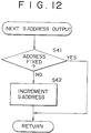
- step S28 the control sequence then advances to step S28, at which it is determined whether or not the variable N is equal to 0. If it is determined at step S28 that the variable N is not equal to 0, the control sequence advances to step S29, at which outputting processing of a next address for further reading out data from the peripheral equipment is executed.
- step S29 the bus width table (FIG. 4) read out from the bus width table storage section 14 at step S7 in FIG. 9 is referred to, first at step S41 illustrated in FIG. 12, to determine whether or-not the addressing type of the peripheral equipment from which the data have been read out is the fixed type.
- step S41 If it is determined at step S41 that the addressing type of the peripheral equipment from which the data have been read out is the fixed type, that is, when the address stored in the address buffer 21 need not be incremented or decremented in order to further read out data from the peripheral equipment, the processing is completed skipping the step S42.
- step S41 determines whether the addressing type of the peripheral equipment from which the data have been read out is not the fixed type but the variable type. If it is determined at step S41 that the addressing type of the peripheral equipment from which the data have been read out is not the fixed type but the variable type, the control sequence advances to step S42, at which the address stored in the address buffer 21 is incremented by one, thereby completing the processing.
- step S29 of FIG. 10 After the outputting processing for a next address is completed in such a manner as described above, that is, after processing at step S29 of FIG. 10 has been completed, the control sequence returns to step S21 until it is determined at step S28 that the variable N is equal to 0, the processing at step S21 to S29 are repeated.
- step S28 when it is determined at step S28 that the variable N is equal to 0, that is, when the data length of the data successively latched from the lower bit side thereof by the data buffer 11 becomes equal to the accessing type of the CPU 1 as a result of the processing at steps S21 to S29 described above, the control sequence advances to step S30, at which the data latched in the data buffer 11 are supplied to the CPU 1 by way of the main bus 9, thereby completing the processing.
- step S14 After the reading processing of data from the peripheral equipment is completed in such a manner as described above, that is, after the processing at step S13 of FIG. 9 is completed, the control sequence advances to step S14.
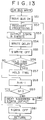
- step S11 of FIG. 9 determines whether the signal outputted from the CPU 1 at step S1 is a write signal. If it is determined at step S11 of FIG. 9 that the signal outputted from the CPU 1 at step S1 is a write signal, the control sequence advances to step S12, at which writing processing of data into the peripheral equipment is executed.
- step S12 the data outputted from the CPU 1 by way of the main bus 9 are first latched by the data buffer 11. Then at step S51 illustrated in FIG. 13, a signal DataOK is outputted to the CPU 1, whereafter the control sequence advances to step S52.
- the CPU 1 recognizes that writing of data into the peripheral equipment has been completed (although such writing has not actually been completed as yet) as described hereinabove.
- step S52 recovery processing similar to that at step S21 of FIG. 10 (steps S31 to S34 of FIG. 11) described above is executed, whereafter the control sequence advances to step S53, at which the data from the CPU 1 latched in the data buffer 11 are read out from the lower bit side thereof by way of the multiplexers 12a to 12d in accordance with the bus width (8 bits or 16 bits in the present embodiment) of the peripheral equipment, into which the data should be written.
- the data thus read out are outputted as signal SData to the sub bus 10 while a write signal (SWrite) is outputted to the sub bus 10.
- SWrite write signal
- step S54 at which the write delay time of the peripheral equipment, into which it is tried to write data, which is described in the timing table read out from the timing table storage section 13 at step S6 of FIG. 9, is referred to to place a waiting time corresponding to the write delay time.
- step S55 outputting of the write signal (SWrite) is stopped at step S55, and then it is determined at step S56 whether or not the peripheral equipment into which the data have been written has a hold time. If it is determined at step S56 that the peripheral equipment into which the data have been written has a hold time, the control sequence advances to step S57, at which a waiting time for the hold time is placed, whereafter the control sequence advances to step S58.
- step S56 if it is determined at step S56 that the peripheral equipment into which the data have been written does not have a hold time, the control sequence advances, skipping the step S57, to step S58, at which the variable N is decremented by one.
- step S59 at which it is determined whether or not the variable N is equal to 0. If it is determined at step S59 that the variable N is not equal to 0, the control sequence advances to step S60, at which outputting processing of a next address and next data for further writing data into the peripheral equipment is executed.
- step S60 the bus width table (FIG. 4) read out from the bus width table storage section 14 at step S7 of FIG. 9 is first referred to at step S71 illustrated in FIG. 14 to determine whether or not the bus width of the peripheral equipment into which the data have been written is 8 bits.
- step S71 If it is determined at step S71 that the bus width of the peripheral equipment into which the data have been written is not 8 bits, that is, when the bus width is 16 bits (in the present embodiment, the bus width of the peripheral equipment connected to the sub bus 10 is either 8 bits or 16 bits), the control sequence advances to step S72, at which the upper 16 bits of the 32-bit data latched in the data buffer 11 are outputted to the multiplexers 12a and 12b, whereafter the control sequence advances to step S74.
- step S71 if it is determined at step S71 that the bus width of the peripheral equipment into which the data have been written is 8 bits, the control sequence advances to step S73, at which upper 8 bits next to the 8 bits outputted last from among the 32-bit data latched in the data buffer 11 are outputted to the multiplexer 12c (or 12b or 12a), whereafter the control sequence advances to step S74.
- the bus width table (FIG. 4) is referred to again to determine whether or not the addressing type of the peripheral equipment into which the data have been written is the fixed type.
- step S74 If it is determined at step S74 that the addressing type of the peripheral equipment into which the data have been written is the fixed type, that is, when the address stored in the address buffer 21 need not be incremented or decremented in order to further write data into the peripheral equipment, the processing is completed skipping the step S75.
- step S74 determines whether the addressing type of the peripheral equipment into which the data have been written is not the fixed type but the variable type. If it is determined at step S74 that the addressing type of the peripheral equipment into which the data have been written is not the fixed type but the variable type, the control sequence advances to step S75, at which the address stored in the address buffer 21 is incremented by one, thereby completing the processing.
- control sequence After the outputting processing of a next address and next data is completed in such a manner as described above, that is, after the processing at step S60 of FIG. 13 is completed, the control sequence returns to step S51 in order to repeat the processing at steps S51 to S60 until after it is determined at step S59 that the variable N is equal to 0.
- data are successively read out from the lower bit side thereof from the data buffer 11, in which the data from the CPU 1 are stored, in accordance with the bus width of the peripheral equipment to unpack and write the data into the peripheral equipment.
- the processing just described is repeated by the number of times given by (accessing type of the CPU 1)/(bus width of the peripheral equipment).
- step S59 if it is determined at step S59 that the variable N is equal to 0, that is, when the data stored in the data buffer 11 have been successively read out from the lower bit side thereof and all written into the peripheral equipment as a result of the processing at steps S51 to S60, the control sequence advances to step S61, at which outputting of the data (SData) to the peripheral equipment is stopped, thereby completing the processing.
- control sequence successively advances to steps S14 and S15, at which outputting of the chip select signal and the address (SAddress), which has been outputted to the peripheral apparatus, is stopped.
- control sequence returns to step S1 to repeat the processing beginning with step S1.
- the processing speed of the entire apparatus can be enhanced and an application program which is reduced in dependency upon hardware can be provided.
Priority Applications (1)
| Application Number | Priority Date | Filing Date | Title |
|---|---|---|---|
| EP02000578A EP1197871A3 (de) | 1993-05-14 | 1994-05-09 | Bussteuerungsvorrichtung |
Applications Claiming Priority (3)
| Application Number | Priority Date | Filing Date | Title |
|---|---|---|---|
| JP112841/93 | 1993-05-14 | ||
| JP11284193 | 1993-05-14 | ||
| JP11284193A JP3608804B2 (ja) | 1993-05-14 | 1993-05-14 | バス制御装置 |
Related Child Applications (2)
| Application Number | Title | Priority Date | Filing Date |
|---|---|---|---|
| EP02000578A Division EP1197871A3 (de) | 1993-05-14 | 1994-05-09 | Bussteuerungsvorrichtung |
| EP02000578A Division-Into EP1197871A3 (de) | 1993-05-14 | 1994-05-09 | Bussteuerungsvorrichtung |
Publications (3)
| Publication Number | Publication Date |
|---|---|
| EP0624846A2 true EP0624846A2 (de) | 1994-11-17 |
| EP0624846A3 EP0624846A3 (de) | 1995-01-18 |
| EP0624846B1 EP0624846B1 (de) | 2003-01-29 |
Family
ID=14596876
Family Applications (2)
| Application Number | Title | Priority Date | Filing Date |
|---|---|---|---|
| EP94303326A Expired - Lifetime EP0624846B1 (de) | 1993-05-14 | 1994-05-09 | Bussteuereinrichtung |
| EP02000578A Withdrawn EP1197871A3 (de) | 1993-05-14 | 1994-05-09 | Bussteuerungsvorrichtung |
Family Applications After (1)
| Application Number | Title | Priority Date | Filing Date |
|---|---|---|---|
| EP02000578A Withdrawn EP1197871A3 (de) | 1993-05-14 | 1994-05-09 | Bussteuerungsvorrichtung |
Country Status (7)
| Country | Link |
|---|---|
| US (2) | US5682555A (de) |
| EP (2) | EP0624846B1 (de) |
| JP (1) | JP3608804B2 (de) |
| KR (1) | KR100319331B1 (de) |
| DE (1) | DE69432063T2 (de) |
| MY (1) | MY110919A (de) |
| TW (1) | TW535941U (de) |
Cited By (5)
| Publication number | Priority date | Publication date | Assignee | Title |
|---|---|---|---|---|
| EP0766180A2 (de) * | 1995-09-29 | 1997-04-02 | International Business Machines Corporation | Informationsverarbeitungssystem mit Bus-zu-Bus-Umsetzung |
| EP0809189A2 (de) * | 1996-05-24 | 1997-11-26 | Oki Electric Industry Co., Ltd. | Datenverriegler für Hochgeschwindigkeitsperipherie |
| WO2001006369A1 (en) * | 1999-07-15 | 2001-01-25 | Teradyne, Inc. | Extending synchronous busses by arbitrary lengths using native bus protocol |
| WO2004051491A1 (en) * | 2002-11-29 | 2004-06-17 | Nokia Corporation | A method and a system for detecting bus width, an electronic device, and a peripheral device |
| CN1299214C (zh) * | 2004-03-12 | 2007-02-07 | 南京大学 | 一种pci接口ad总线再复用的方法 |
Families Citing this family (9)
| Publication number | Priority date | Publication date | Assignee | Title |
|---|---|---|---|---|
| TW315559B (en) * | 1996-03-19 | 1997-09-11 | Hitachi Ltd | Communication control device and communication system thereof |
| US6016527A (en) * | 1996-09-30 | 2000-01-18 | Lsi Logic Corporation | Method and apparatus for improving fairness in SCSI bus arbitration |
| US6336159B1 (en) * | 1997-06-25 | 2002-01-01 | Intel Corporation | Method and apparatus for transferring data in source-synchronous protocol and transferring signals in common clock protocol in multiple agent processing system |
| US7366843B2 (en) * | 2002-06-28 | 2008-04-29 | Sun Microsystems, Inc. | Computer system implementing synchronized broadcast using timestamps |
| US7103701B2 (en) * | 2002-09-23 | 2006-09-05 | Hewlett-Packard Development Company, L.P. | Memory bus interface |
| US6775191B1 (en) * | 2002-10-22 | 2004-08-10 | Silicon Magnetic Systems | Memory circuit with selective address path |
| KR100532471B1 (ko) * | 2003-09-26 | 2005-12-01 | 삼성전자주식회사 | 입출력 데이터 위스 조절이 가능한 메모리 장치 및 그위스 조절 방법 |
| US7366864B2 (en) * | 2004-03-08 | 2008-04-29 | Micron Technology, Inc. | Memory hub architecture having programmable lane widths |
| US8370581B2 (en) | 2005-06-30 | 2013-02-05 | Intel Corporation | System and method for dynamic data prefetching |
Citations (2)
| Publication number | Priority date | Publication date | Assignee | Title |
|---|---|---|---|---|
| EP0339224A2 (de) * | 1988-04-29 | 1989-11-02 | International Business Machines Corporation | Speicheransteuerschaltung |
| EP0479428A1 (de) * | 1990-10-01 | 1992-04-08 | International Business Machines Corporation | Datenverarbeitungsvorrichtung zur dynamischen Zeiteinstellung in einem dynamischen Speichersystem |
Family Cites Families (23)
| Publication number | Priority date | Publication date | Assignee | Title |
|---|---|---|---|---|
| FR2576432B1 (fr) * | 1985-01-24 | 1989-06-02 | Brion Alain | Dispositif d'echange de donnees entre un calculateur et une unite peripherique |
| JPS61175845A (ja) * | 1985-01-31 | 1986-08-07 | Toshiba Corp | マイクロプロセツサシステム |
| JPS6226561A (ja) * | 1985-07-26 | 1987-02-04 | Toshiba Corp | パ−ソナルコンピユ−タ |
| US4947368A (en) * | 1987-05-01 | 1990-08-07 | Digital Equipment Corporation | Lookahead bus arbitration system with override of conditional access grants by bus cycle extensions for multicycle data transfers |
| US5155812A (en) * | 1989-05-04 | 1992-10-13 | Texas Instruments Incorporated | Devices and method for generating and using systems, software waitstates on address boundaries in data processing |
| GB2211326B (en) * | 1987-10-16 | 1991-12-11 | Hitachi Ltd | Address bus control apparatus |
| US4878166A (en) * | 1987-12-15 | 1989-10-31 | Advanced Micro Devices, Inc. | Direct memory access apparatus and methods for transferring data between buses having different performance characteristics |
| US5301278A (en) * | 1988-04-29 | 1994-04-05 | International Business Machines Corporation | Flexible dynamic memory controller |
| US5274781A (en) * | 1988-07-25 | 1993-12-28 | Allen-Bradley Company, Inc. | Programmable controller module identification by interconnecting the input and output ports of a module in a predefined manner |
| US5193193A (en) * | 1988-09-14 | 1993-03-09 | Silicon Graphics, Inc. | Bus control system for arbitrating requests with predetermined on/off time limitations |
| US5274767A (en) * | 1988-09-23 | 1993-12-28 | Allen-Bradley Company, Inc. | Programmable controller with module identification and diagnostic mechanism |
| US5287457A (en) * | 1989-01-13 | 1994-02-15 | International Business Machines Corporation | Computer system DMA transfer |
| US5416907A (en) * | 1990-06-15 | 1995-05-16 | Digital Equipment Corporation | Method and apparatus for transferring data processing data transfer sizes |
| US5287528A (en) * | 1990-07-03 | 1994-02-15 | National Instruments Corporation | IEEE 488 interface for message handling method |
| JPH0470946A (ja) * | 1990-07-04 | 1992-03-05 | Mitsubishi Electric Corp | Dmaコントローラを内蔵した処理装置 |
| EP0466970B1 (de) * | 1990-07-20 | 2004-09-22 | Infineon Technologies AG | Mikroprozessor mit einer Vielzahl von Buskonfigurationen |
| JPH04157550A (ja) * | 1990-10-22 | 1992-05-29 | Toshiba Corp | パーソナルコンピュータシステム |
| EP0836349A3 (de) * | 1990-11-29 | 1999-06-02 | Fujitsu Limited | ISDN Schnittstelle |
| JPH05173938A (ja) * | 1991-10-08 | 1993-07-13 | Fujitsu Ltd | 間欠dma制御方式 |
| EP0539782B1 (de) * | 1991-10-28 | 1999-04-21 | Eastman Kodak Company | Steuerungsschaltung zur Datenübertragung von einem VME-Bus zu einer SCSI-Platteneinheit |
| JP2836321B2 (ja) * | 1991-11-05 | 1998-12-14 | 三菱電機株式会社 | データ処理装置 |
| JPH05173932A (ja) * | 1991-12-24 | 1993-07-13 | Toshiba Corp | データ転送装置 |
| US5241632A (en) * | 1992-01-30 | 1993-08-31 | Digital Equipment Corporation | Programmable priority arbiter |
-
1993
- 1993-05-14 JP JP11284193A patent/JP3608804B2/ja not_active Expired - Lifetime
-
1994
- 1994-04-19 TW TW089213161U patent/TW535941U/zh not_active IP Right Cessation
- 1994-05-09 DE DE69432063T patent/DE69432063T2/de not_active Expired - Lifetime
- 1994-05-09 EP EP94303326A patent/EP0624846B1/de not_active Expired - Lifetime
- 1994-05-09 EP EP02000578A patent/EP1197871A3/de not_active Withdrawn
- 1994-05-11 MY MYPI94001182A patent/MY110919A/en unknown
- 1994-05-12 KR KR1019940010356A patent/KR100319331B1/ko not_active IP Right Cessation
-
1995
- 1995-11-02 US US08/556,803 patent/US5682555A/en not_active Expired - Lifetime
-
1996
- 1996-09-03 US US08/707,059 patent/US5935428A/en not_active Expired - Lifetime
Patent Citations (2)
| Publication number | Priority date | Publication date | Assignee | Title |
|---|---|---|---|---|
| EP0339224A2 (de) * | 1988-04-29 | 1989-11-02 | International Business Machines Corporation | Speicheransteuerschaltung |
| EP0479428A1 (de) * | 1990-10-01 | 1992-04-08 | International Business Machines Corporation | Datenverarbeitungsvorrichtung zur dynamischen Zeiteinstellung in einem dynamischen Speichersystem |
Cited By (9)
| Publication number | Priority date | Publication date | Assignee | Title |
|---|---|---|---|---|
| EP0766180A2 (de) * | 1995-09-29 | 1997-04-02 | International Business Machines Corporation | Informationsverarbeitungssystem mit Bus-zu-Bus-Umsetzung |
| EP0766180A3 (de) * | 1995-09-29 | 1997-04-09 | Ibm | |
| EP0809189A2 (de) * | 1996-05-24 | 1997-11-26 | Oki Electric Industry Co., Ltd. | Datenverriegler für Hochgeschwindigkeitsperipherie |
| EP0809189A3 (de) * | 1996-05-24 | 1998-04-08 | Oki Electric Industry Co., Ltd. | Datenverriegler für Hochgeschwindigkeitsperipherie |
| US6098164A (en) * | 1996-05-24 | 2000-08-01 | Oki Electric Industry Co., Ltd. | Microprocessor with common bus for memory and peripheral circuit having data latch generator |
| WO2001006369A1 (en) * | 1999-07-15 | 2001-01-25 | Teradyne, Inc. | Extending synchronous busses by arbitrary lengths using native bus protocol |
| AU775255B2 (en) * | 1999-07-15 | 2004-07-22 | Teradyne, Inc. | Extending synchronous busses by arbitrary lengths using native bus protocol |
| WO2004051491A1 (en) * | 2002-11-29 | 2004-06-17 | Nokia Corporation | A method and a system for detecting bus width, an electronic device, and a peripheral device |
| CN1299214C (zh) * | 2004-03-12 | 2007-02-07 | 南京大学 | 一种pci接口ad总线再复用的方法 |
Also Published As
| Publication number | Publication date |
|---|---|
| DE69432063T2 (de) | 2003-10-30 |
| US5682555A (en) | 1997-10-28 |
| EP0624846A3 (de) | 1995-01-18 |
| US5935428A (en) | 1999-08-10 |
| JPH06324990A (ja) | 1994-11-25 |
| EP1197871A3 (de) | 2009-09-30 |
| MY110919A (en) | 1999-06-30 |
| JP3608804B2 (ja) | 2005-01-12 |
| EP0624846B1 (de) | 2003-01-29 |
| DE69432063D1 (de) | 2003-03-06 |
| KR100319331B1 (ko) | 2002-04-06 |
| EP1197871A2 (de) | 2002-04-17 |
| TW535941U (en) | 2003-06-01 |
Similar Documents
| Publication | Publication Date | Title |
|---|---|---|
| EP0624846B1 (de) | Bussteuereinrichtung | |
| JP4936506B2 (ja) | メモリ制御回路及びメモリ制御方法 | |
| US4384342A (en) | System for reducing access time to plural memory modules using five present-fetch and one prefetch address registers | |
| US5333294A (en) | Configurable data width direct memory access device with a read address counter and a write address counter which increments the addresses based on the desired data transfer width | |
| EP0549139A1 (de) | Programmierbare Zeitsteuerung für Speicher | |
| WO2000020978A1 (en) | Memory controller with programmable delay counter for tuning performance based on timing parameter of controlled memory storage device | |
| US4841435A (en) | Data alignment system for random and block transfers of embedded subarrays of an array onto a system bus | |
| US7165126B2 (en) | Direct memory access device | |
| US20050180240A1 (en) | Method and system for fast memory access | |
| US4473879A (en) | Data transfer system in which time for transfer of data to a memory is matched to time required to store data in memory | |
| KR970071302A (ko) | 프로세서로부터의 프로그램가능한 판독/기록 억세스 신호 및 이 신호의 형성 방법 | |
| US5430844A (en) | Communication control system for transmitting, from one data processing device to another, data along with an identification of the address at which the data is to be stored upon reception | |
| US5588120A (en) | Communication control system for transmitting, from one data processing device to another, data of different formats along with an identification of the format and its corresponding DMA controller | |
| US5412777A (en) | Display device having a built-in memory | |
| JPH11259417A (ja) | バスアクセス方式およびバスアクセス制御装置 | |
| EP0619546A1 (de) | Programmierbare Speichersteuerungsvorrichtung und Verfahren zu ihren Konfigurierung | |
| US6486704B1 (en) | Programmable burst FIFO | |
| JP3304395B2 (ja) | データ転送装置及びデータ転送方法 | |
| EP1459291B1 (de) | Digitale leitungsverzögerung mit einem einzelportspeicher | |
| JP2001034573A (ja) | メモリアクセスシステム及び方法 | |
| US7506133B2 (en) | Method and apparatus for high speed addressing of a memory space from a relatively small address space | |
| JP3496942B2 (ja) | メモリアクセス方法 | |
| JP2002050172A (ja) | Fifo制御回路 | |
| JPH082756Y2 (ja) | 画像処理装置 | |
| JPH081633B2 (ja) | データ転送装置 |
Legal Events
| Date | Code | Title | Description |
|---|---|---|---|
| PUAI | Public reference made under article 153(3) epc to a published international application that has entered the european phase |
Free format text: ORIGINAL CODE: 0009012 |
|
| AK | Designated contracting states |
Kind code of ref document: A2 Designated state(s): DE FR GB |
|
| PUAL | Search report despatched |
Free format text: ORIGINAL CODE: 0009013 |
|
| AK | Designated contracting states |
Kind code of ref document: A3 Designated state(s): DE FR GB |
|
| 17P | Request for examination filed |
Effective date: 19950620 |
|
| RAP1 | Party data changed (applicant data changed or rights of an application transferred) |
Owner name: SONY COMPUTER ENTERTAINMENT INC. |
|
| 17Q | First examination report despatched |
Effective date: 20010822 |
|
| GRAH | Despatch of communication of intention to grant a patent |
Free format text: ORIGINAL CODE: EPIDOS IGRA |
|
| GRAH | Despatch of communication of intention to grant a patent |
Free format text: ORIGINAL CODE: EPIDOS IGRA |
|
| GRAA | (expected) grant |
Free format text: ORIGINAL CODE: 0009210 |
|
| AK | Designated contracting states |
Designated state(s): DE FR GB |
|
| REG | Reference to a national code |
Ref country code: GB Ref legal event code: FG4D |
|
| REF | Corresponds to: |
Ref document number: 69432063 Country of ref document: DE Date of ref document: 20030306 Kind code of ref document: P |
|
| ET | Fr: translation filed | ||
| PLBE | No opposition filed within time limit |
Free format text: ORIGINAL CODE: 0009261 |
|
| STAA | Information on the status of an ep patent application or granted ep patent |
Free format text: STATUS: NO OPPOSITION FILED WITHIN TIME LIMIT |
|
| 26N | No opposition filed |
Effective date: 20031030 |
|
| PGFP | Annual fee paid to national office [announced via postgrant information from national office to epo] |
Ref country code: GB Payment date: 20130508 Year of fee payment: 20 Ref country code: DE Payment date: 20130515 Year of fee payment: 20 |
|
| PGFP | Annual fee paid to national office [announced via postgrant information from national office to epo] |
Ref country code: FR Payment date: 20130531 Year of fee payment: 20 |
|
| REG | Reference to a national code |
Ref country code: DE Ref legal event code: R071 Ref document number: 69432063 Country of ref document: DE |
|
| REG | Reference to a national code |
Ref country code: GB Ref legal event code: PE20 Expiry date: 20140508 |
|
| PG25 | Lapsed in a contracting state [announced via postgrant information from national office to epo] |
Ref country code: GB Free format text: LAPSE BECAUSE OF EXPIRATION OF PROTECTION Effective date: 20140508 |
|
| PG25 | Lapsed in a contracting state [announced via postgrant information from national office to epo] |
Ref country code: DE Free format text: LAPSE BECAUSE OF EXPIRATION OF PROTECTION Effective date: 20140510 |