EP0623948A1 - Load lock chamber for vertical type heat treatment apparatus - Google Patents
Load lock chamber for vertical type heat treatment apparatus Download PDFInfo
- Publication number
- EP0623948A1 EP0623948A1 EP93924820A EP93924820A EP0623948A1 EP 0623948 A1 EP0623948 A1 EP 0623948A1 EP 93924820 A EP93924820 A EP 93924820A EP 93924820 A EP93924820 A EP 93924820A EP 0623948 A1 EP0623948 A1 EP 0623948A1
- Authority
- EP
- European Patent Office
- Prior art keywords
- chamber
- load lock
- lock chamber
- heat treatment
- type heat
- Prior art date
- Legal status (The legal status is an assumption and is not a legal conclusion. Google has not performed a legal analysis and makes no representation as to the accuracy of the status listed.)
- Withdrawn
Links
Images
Classifications
-
- H—ELECTRICITY
- H01—ELECTRIC ELEMENTS
- H01L—SEMICONDUCTOR DEVICES NOT COVERED BY CLASS H10
- H01L21/00—Processes or apparatus adapted for the manufacture or treatment of semiconductor or solid state devices or of parts thereof
- H01L21/67—Apparatus specially adapted for handling semiconductor or electric solid state devices during manufacture or treatment thereof; Apparatus specially adapted for handling wafers during manufacture or treatment of semiconductor or electric solid state devices or components ; Apparatus not specifically provided for elsewhere
- H01L21/677—Apparatus specially adapted for handling semiconductor or electric solid state devices during manufacture or treatment thereof; Apparatus specially adapted for handling wafers during manufacture or treatment of semiconductor or electric solid state devices or components ; Apparatus not specifically provided for elsewhere for conveying, e.g. between different workstations
- H01L21/67739—Apparatus specially adapted for handling semiconductor or electric solid state devices during manufacture or treatment thereof; Apparatus specially adapted for handling wafers during manufacture or treatment of semiconductor or electric solid state devices or components ; Apparatus not specifically provided for elsewhere for conveying, e.g. between different workstations into and out of processing chamber
- H01L21/67757—Apparatus specially adapted for handling semiconductor or electric solid state devices during manufacture or treatment thereof; Apparatus specially adapted for handling wafers during manufacture or treatment of semiconductor or electric solid state devices or components ; Apparatus not specifically provided for elsewhere for conveying, e.g. between different workstations into and out of processing chamber vertical transfer of a batch of workpieces
-
- H—ELECTRICITY
- H01—ELECTRIC ELEMENTS
- H01L—SEMICONDUCTOR DEVICES NOT COVERED BY CLASS H10
- H01L21/00—Processes or apparatus adapted for the manufacture or treatment of semiconductor or solid state devices or of parts thereof
- H01L21/67—Apparatus specially adapted for handling semiconductor or electric solid state devices during manufacture or treatment thereof; Apparatus specially adapted for handling wafers during manufacture or treatment of semiconductor or electric solid state devices or components ; Apparatus not specifically provided for elsewhere
- H01L21/67005—Apparatus not specifically provided for elsewhere
- H01L21/67011—Apparatus for manufacture or treatment
- H01L21/67098—Apparatus for thermal treatment
-
- Y—GENERAL TAGGING OF NEW TECHNOLOGICAL DEVELOPMENTS; GENERAL TAGGING OF CROSS-SECTIONAL TECHNOLOGIES SPANNING OVER SEVERAL SECTIONS OF THE IPC; TECHNICAL SUBJECTS COVERED BY FORMER USPC CROSS-REFERENCE ART COLLECTIONS [XRACs] AND DIGESTS
- Y10—TECHNICAL SUBJECTS COVERED BY FORMER USPC
- Y10S—TECHNICAL SUBJECTS COVERED BY FORMER USPC CROSS-REFERENCE ART COLLECTIONS [XRACs] AND DIGESTS
- Y10S414/00—Material or article handling
- Y10S414/135—Associated with semiconductor wafer handling
- Y10S414/139—Associated with semiconductor wafer handling including wafer charging or discharging means for vacuum chamber
Definitions
- the present invention relates generally to a load locked vertical type heat treatment apparatus, and more specifically to a load lock chamber provided to a load locked vertical vertical type heat treatment apparatus.
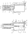
- Fig.3(a) shows a partial cross sectional view of a load locked vertical type heat treatment apparatus.
- the load locked vertical type heat treatment apparatus is comprised of a treatment chamber 1 and an elevator chamber 11.
- a reaction tube 2 is provided in the treatment chamber 1, and a compartment tube 3 is provided in the reaction tube 2.
- a manifold 4 which is provided with a gas inlet 9 for introducing a gas into the treatment chamber 1 and a gas outlet 10 for exhausting the gas is mounted below the treatment chamber 1.
- a heater is positioned around the reaction tube 2 so that the reaction tube 2, objects 7 inside the reaction tube and the like can be heated.
- objects supporting boats 5 and a boat table 6 for supporting the boats 5 placing a plurality of objects 7, such as semiconductor wafers 7, in vertical direction with spaces between them are provided so that they can be loaded into and unloaded from the compartment tube 3 through the manifold 4.
- a treatment to objects 7 is to form a thin film by a chemical vapor deposition and is annealing or the like.
- the elevator chamber 11 is connected below the treatment chamber 1 through the manifold 4.
- the elevator chamber 11 is communicated with the treatment chamber 1 through an opening 11a provided at the top of the elevator chamber 11 and an opening 4a (Fig.3b), of which diameter is smaller than the opening 11a (Fig.3), of the manifold 4.
- Fig.3b an opening 4a (Fig.3b), of which diameter is smaller than the opening 11a (Fig.3), of the manifold 4.
- untreated objects are placed to the objects supporting boats 5, or treated objects removed from the boats 5.
- a sealing flange 8 with an outer diameter larger than the opening 4a and an inner diameter smaller than the opening 11a is mounted on the bottom surface of the boat table 6.
- the sealing flange 8 is contacted to a shoulder formed between the opening 4a and the opening 11a to open and close an interior space of the treatment chamber 1. By such opening and closing, the treatment chamber 1 is completely separated from an interior space of the elevator chamber 11.
- a movable member 12 is horizontally extended and provided below the sealing flange 8, and a hole which is threaded is provided about its one end.
- a feed screw 13 screwed into the hole is extended upwardly and downwardly through the hole.
- the upper end of the feed screw 13 is mounted rotatably on an upper wall of the elevator chamber 11.
- the lower end is extended outside the elevator chamber 11 passing through the bottom of the elevator chamber 11 via an O-ring 13a by which the interior of the elevator chamber 11 is maintained in vacuum.
- a pulley 15b is mounted about the end of the feed screw which is extended outside the elevator chamber 11, and the pulley 15b is connected to a pulley 15a provided about an end of a motor 14 provided on a side wall out side the elevator chamber 11 by a belt 16.
- the motor 14 rotates the motor 14, the rotation is transferred to the feed screw, so that the movable member 12 is traveled upwardly and downwardly. Accordingly, the boat table 6 can be moved from the interior of the elevator chamber 11 to the treatment chamber 1, and vise versa. Whenever it is necessary to exhaust from the elevator chamber 11, the exhaust can be done through an outlet 17.
- Fig.3b shows a partial cross sectional view of the heat treatment apparatus when the boat table 6 has been descended until the objects are also completely contained inside the elevator chamber 11.
- the boat 5 When placing objects to the objects supporting boats, the boat 5 is descended into the elevator chamber 11 as shown in Fig.3b, untreated objects are supplied to the boat 5 through an opening 20 and a gate valve 18. After the treatment, in the similar manner, the boat 5 is descended, treated objects are returned to a room 19.
- an objective of the present invention is to provide a load lock chamber for a vertical type heat treatment apparatus which has no elevating device which requires the provision of lubricating oil which is a source of particles causing contamination in the elevator chamber.
- Another objective of the present invention is to provide the load lock chamber for the vertical type heat treatment apparatus which can rotate a boat table supporting objects from the exterior.
- a load lock chamber for a vertical type heat treatment apparatus of the present invention is a load lock chamber which can be freely expanded in vertical direction and is arranged below a treatment chamber of the vertical type heat treatment apparatus and can gastightly load supporting means for supporting objects into the apparatus and unload the supporting means from the apparatus through the lower part of the apparatus, and the load lock chamber is expanded by elevating means provided outside the load lock chamber.
- the supporting means is mounted in the load lock chamber.
- the load lock chamber may be comprised of two chamber sections such as an upper and a lower chamber section, of which sizes are different, and which are connected in vertical direction.
- the two chamber sections are preferably nested.
- the load lock chamber is preferably a metal bellows, and elevating means are preferably comprised of a feed screw; a movable member screwed by a feed screw extending vertically and engaged with a bottom of the load lock chamber; if two bellows are used, connecting means; and means for rotating the feed screw.
- a vertical type heat treatment apparatus of the present invention contracts by elevating means provided outside, and according to the contraction objects supported by a supporting body are loaded into a treatment chamber, and then transferred therefrom.
- the outer side of the bottom of the supporing body can be under atmospheric air condition, so that means for rotating the supporting body can be accessed from the exterior.
- the elevating means are provided outside the load lock chamber, so that particles caused by the elevation and the like do not penetrate into the chamber.
- Fig.1a shows a partial cross sectional view of a load lock chamber for a vertical type heat treatment apparatus in accordance with the present invention of which the boat table has been elevated downwardly to its lower position
- Fig. 1b shows a partial cross sectional view of a load lock chamber for a vertical heat treatment apparatus in accordance with the present invention of which the boat table has been elevated downwardly to its lower position.
- Fig.2a shows a partial cross sectional view of another load lock chamber for a vertical type heat treatment apparatus in accordance with the present invention of which boat table has been elevated upwardly to its upper position
- Fig.2b shows another load lock chamber for a vertical type heat treatment apparatus in accordance with the present invention of which boat table has been elevated downwardly to its lower position.
- Fig.3a shows a cross sectional view of a load lock chamber for a vertical type heat treatment apparatus in accordance with the art of which boat table has been elevated upwardly to its upper position
- Fig.2b shows a partial cross sectional view of a load lock chamber for a vertical type heat treatment apparatus in accordance with the art of which boat table has been elevated downwardly until its lower position.
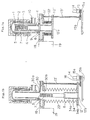
- Fig.1 shows a partial cross sectional view of a load lock chamber for a vertical type heat treatment apparatus in accordance with the present invention, and Fig.1a shows a state that the load lock chamber has been contracted and Fig.1b shows a state that the load lock chamber has been extended.
- an intermediate chamber 30 is mounted below a manifold 4, and the intermediate chamber 30 is communicated with a treatment chamber 1 by an opening 30a of which diameter is larger than a sealing flange 8. Also, the intermediate chamber 30 has an outlet 17 and a room 19 for supplying and removing objects via a gate valve 18, likewise in Fig.3. Moreover, an opening 30b of which diameter is almost the same size as the opening 30a is provided in the intermediate chamber 30.
- a cylinder section 34a of which diameter is the same size as the sealing flange 8 and a supporting stand 12 comprising a flange 34b provided on a lower end thereof are mounted below the sealing flange 8 and are communicated through the opening 30b and extended outwardly. While the flange 34b is fixed on a movable member 12', a metal bellows 22 is mounted gastightly between the flange 34 and the intermediate chamber 30 so that the load lock chamber is formed, and a boat table 6 and a supporting boat 5 are isolated from the exterior.
- An opening 12'a which has the same size as the inner diameter of the cylinder section 34a is provided in the movable member 12', and the lower surface of the sealing flange 8 is exposed to the exterior. Therefore, a mechanism for rotation can be installed through the sealing flange 8 from the exterior. For example, by communicating rotatably and gastightly a rotational shaft of a motor for the rotational mechanism from the lower part of the sealing flange 8 and by directly connecting the rotational shaft to the boat table 6 positioned above the sealing flange 8, the boat table 6 can be directly rotated externally.
- a rotation of the motor 14 is transferred to the feed screw 13' by a belt 16 connecting between a pulley 15b provided about the lower end of the feed screw 13' and a pulley 15a provided in the motor 14. While the movable member 12' is elevated by rotating the feed screw 13' so that boat table 6 can be elevated, the bellows 12' follows this elevation so that the interior of the load lock chamber can be maintained in gastight.
- Fig.1 shows a state of the load lock chamber when the movable member 12' has been moved to the lowest position. In this position, objects can be placed to or removed from the objects supporting boat.
- Fig.2 shows another embodiment of the present invention. This embodiment differs from the embodiment shown in Fig.1, in that two bellows are utilized.
- a supporting stand comprising of a cylinder section 34a and a flange 34b is provided below the sealing flange 8, and the flange 34b is mounted on a first movable member 12a having an opening 12a'.
- the first movable member 12a can be elevated by rotating a first feed screw 13a, as same as in Fig.1.
- a first bellows 22a which has a small diameter and of which lower end is gastightly mounted on the flange 34b, is arranged around the cylinder section 34a of the supporting stand 34. Cylindrical connecting means are positioned outside the bellows 22a, and the upper end of the first bellows 22a is gastightly mounted on a first flange 23a extended inwardly in radial direction in the upper end of the connecting means 23.
- the lower end of the connecting means 23 has a flange 23b extending outwardly in the radial direction, and the flange 23b has a hole to screw a second feed screw 13b similar to the first feed screw 13'a and is gastightly mounted on a second movable member 12b which is elevated by rotating a second feed screw 13b.
- the second movable member 12b has also a central opening section capable of communicating the first bellows 22a.
- a second bellows 22b of which diameter is larger size than the connecting means 23, is gastightly mounted between a lower end of an intermediate chamber 17 and the flange 23b of the connecting means 23 and surrounding the connecting means 23.
- the diameter of the first bellows may be larger and the diameter of the second bellows may be smaller. Also, although the whole length is longer, the diameters of two bellows may be set in equal, and they can be connected by the connecting means.
- the load lock chamber is formed by the first and the second bellows so that the boat table 6 and the supporting boat 5 are isolated from the exterior.
- the expansions of the bellows can be done in the same amount by changing a screw pitch of each feed screw or by providing motor means for rotating each feed screw to adjust the rotation of each of the motor means.
- elevation of the movable member has been performed by a feed screw in two embodiments mentioned above, such elevation may be done by elevating means such as air or oil cylinder in stead of the feed screw.
- the load lock chamber for a vertical type heat treatment apparatus of the present invention provides means for elevating a boat table supporting objects in the exterior thereof, and the load lock chamber is always maintained in gastight and is not contaminated by particles caused by the elevation thereby.
- the load lock chamber is made of a flexible member such as a bellows and the elevating means are provided in the exterior, and the volume of the chamber can be reduced thereby.
- the sealing flange mounted on the boat table is under atmospheric air condition, and the boat table, that is objects, can easily be rotated by accessing a mechanism for rotating the boat table from the exterior thereby.
Abstract
The title chamber has no elevating device which requires the provision of lubricating oil which is a source of particles causing contamination in the chamber. Below a treatment chamber (1) an intermediate chamber (30) is arranged. A supporting stand (34) is provided below the boat table (6) for supporting the objects to be processed, which can be loaded into or unloaded from the treatment chamber (1) gastightly through the intermediate chamber (30). The supporting stand (34) is mounted on a movable member movable vertically by means of a ball screw (13'). A bellows (22) is mounted between the intermediate chamber (30) and the movable member (12').
Description
- The present invention relates generally to a load locked vertical type heat treatment apparatus, and more specifically to a load lock chamber provided to a load locked vertical vertical type heat treatment apparatus.
- Fig.3(a) shows a partial cross sectional view of a load locked vertical type heat treatment apparatus. As shown in Fig.3, the load locked vertical type heat treatment apparatus is comprised of a treatment chamber 1 and an elevator chamber 11.
- A
reaction tube 2 is provided in the treatment chamber 1, and acompartment tube 3 is provided in thereaction tube 2. Amanifold 4 which is provided with agas inlet 9 for introducing a gas into the treatment chamber 1 and agas outlet 10 for exhausting the gas is mounted below the treatment chamber 1. A heater is positioned around thereaction tube 2 so that thereaction tube 2,objects 7 inside the reaction tube and the like can be heated. - In the
compartment tube 3,objects supporting boats 5 and a boat table 6 for supporting theboats 5 placing a plurality ofobjects 7, such assemiconductor wafers 7, in vertical direction with spaces between them are provided so that they can be loaded into and unloaded from thecompartment tube 3 through themanifold 4. A treatment toobjects 7 is to form a thin film by a chemical vapor deposition and is annealing or the like. - The elevator chamber 11 is connected below the treatment chamber 1 through the
manifold 4. The elevator chamber 11 is communicated with the treatment chamber 1 through an opening 11a provided at the top of the elevator chamber 11 and an opening 4a (Fig.3b), of which diameter is smaller than the opening 11a (Fig.3), of themanifold 4. In the elevator chamber 11, untreated objects are placed to theobjects supporting boats 5, or treated objects removed from theboats 5. - A
sealing flange 8 with an outer diameter larger than the opening 4a and an inner diameter smaller than the opening 11a is mounted on the bottom surface of the boat table 6. The sealingflange 8 is contacted to a shoulder formed between the opening 4a and the opening 11a to open and close an interior space of the treatment chamber 1. By such opening and closing, the treatment chamber 1 is completely separated from an interior space of the elevator chamber 11. - A
movable member 12 is horizontally extended and provided below the sealingflange 8, and a hole which is threaded is provided about its one end. Afeed screw 13 screwed into the hole is extended upwardly and downwardly through the hole. The upper end of thefeed screw 13 is mounted rotatably on an upper wall of the elevator chamber 11. The lower end is extended outside the elevator chamber 11 passing through the bottom of the elevator chamber 11 via an O-ring 13a by which the interior of the elevator chamber 11 is maintained in vacuum. - A
pulley 15b is mounted about the end of the feed screw which is extended outside the elevator chamber 11, and thepulley 15b is connected to apulley 15a provided about an end of amotor 14 provided on a side wall out side the elevator chamber 11 by abelt 16. Thus, by rotating themotor 14, the rotation is transferred to the feed screw, so that themovable member 12 is traveled upwardly and downwardly. Accordingly, the boat table 6 can be moved from the interior of the elevator chamber 11 to the treatment chamber 1, and vise versa. Whenever it is necessary to exhaust from the elevator chamber 11, the exhaust can be done through anoutlet 17. - Fig.3b shows a partial cross sectional view of the heat treatment apparatus when the boat table 6 has been descended until the objects are also completely contained inside the elevator chamber 11. When placing objects to the objects supporting boats, the
boat 5 is descended into the elevator chamber 11 as shown in Fig.3b, untreated objects are supplied to theboat 5 through anopening 20 and agate valve 18. After the treatment, in the similar manner, theboat 5 is descended, treated objects are returned to aroom 19. - However, in a load locked vertical type heat treatment apparatus of the art, means for elevating the boat table 6, that is the
movable member 12, and thefeed screw 13 are provided in the elevator chamber 11. Thus, particles are released by rotating thefeed screw 13 and screwing thefeed screw 13 into themovable member 12. - Also, when evacuating the interior of the elevator chamber 11 and elevating the boat table 6, it is required to put lubricating oil to engaging section between the feed screw and the boat table to make the elevation smoothly. Although the lubricating oil has low vapor pressure, an elevating structure inside the elevator chamber 11 is heated by radiation of objects and the like when the objects are unloaded from the treatment chamber 1 after the treatment, thereby evaporating the lubricating oil in the elevator chamber 11, and as a result, the objects are contaminated.
- Moreover, in a vacuum load locked apparatus, because an interior of a chamber is always in a state of vacuum, it is very difficult to provide a mechanism for rotating a boat table for supporting objects.
- Accordingly, an objective of the present invention is to provide a load lock chamber for a vertical type heat treatment apparatus which has no elevating device which requires the provision of lubricating oil which is a source of particles causing contamination in the elevator chamber.
- Another objective of the present invention is to provide the load lock chamber for the vertical type heat treatment apparatus which can rotate a boat table supporting objects from the exterior.
- In order to accomplish the above objectives, a load lock chamber for a vertical type heat treatment apparatus of the present invention is a load lock chamber which can be freely expanded in vertical direction and is arranged below a treatment chamber of the vertical type heat treatment apparatus and can gastightly load supporting means for supporting objects into the apparatus and unload the supporting means from the apparatus through the lower part of the apparatus, and the load lock chamber is expanded by elevating means provided outside the load lock chamber. The supporting means is mounted in the load lock chamber.
- The load lock chamber may be comprised of two chamber sections such as an upper and a lower chamber section, of which sizes are different, and which are connected in vertical direction. The two chamber sections are preferably nested.
- The load lock chamber is preferably a metal bellows, and elevating means are preferably comprised of a feed screw; a movable member screwed by a feed screw extending vertically and engaged with a bottom of the load lock chamber; if two bellows are used, connecting means; and means for rotating the feed screw.
- A vertical type heat treatment apparatus of the present invention contracts by elevating means provided outside, and according to the contraction objects supported by a supporting body are loaded into a treatment chamber, and then transferred therefrom. The outer side of the bottom of the supporing body can be under atmospheric air condition, so that means for rotating the supporting body can be accessed from the exterior.
- The elevating means are provided outside the load lock chamber, so that particles caused by the elevation and the like do not penetrate into the chamber.
- Fig.1a shows a partial cross sectional view of a load lock chamber for a vertical type heat treatment apparatus in accordance with the present invention of which the boat table has been elevated downwardly to its lower position, and Fig. 1b shows a partial cross sectional view of a load lock chamber for a vertical heat treatment apparatus in accordance with the present invention of which the boat table has been elevated downwardly to its lower position.
- Fig.2a shows a partial cross sectional view of another load lock chamber for a vertical type heat treatment apparatus in accordance with the present invention of which boat table has been elevated upwardly to its upper position, and Fig.2b shows another load lock chamber for a vertical type heat treatment apparatus in accordance with the present invention of which boat table has been elevated downwardly to its lower position.
- Fig.3a shows a cross sectional view of a load lock chamber for a vertical type heat treatment apparatus in accordance with the art of which boat table has been elevated upwardly to its upper position, and Fig.2b shows a partial cross sectional view of a load lock chamber for a vertical type heat treatment apparatus in accordance with the art of which boat table has been elevated downwardly until its lower position.
- Fig.1 shows a partial cross sectional view of a load lock chamber for a vertical type heat treatment apparatus in accordance with the present invention, and Fig.1a shows a state that the load lock chamber has been contracted and Fig.1b shows a state that the load lock chamber has been extended.
- The same reference numbers are utilized in the load lock chamber for a vertical type heat treatment apparatus shown in Fig.1, with respect to structural elements commonly used in a load lock chamber for a vertical type heat treatment chamber shown in Fig.3.
- In the apparatus shown in Fig.1, an
intermediate chamber 30 is mounted below amanifold 4, and theintermediate chamber 30 is communicated with a treatment chamber 1 by an opening 30a of which diameter is larger than asealing flange 8. Also, theintermediate chamber 30 has anoutlet 17 and aroom 19 for supplying and removing objects via agate valve 18, likewise in Fig.3. Moreover, an opening 30b of which diameter is almost the same size as the opening 30a is provided in theintermediate chamber 30. - A
cylinder section 34a of which diameter is the same size as thesealing flange 8 and a supportingstand 12 comprising aflange 34b provided on a lower end thereof are mounted below thesealing flange 8 and are communicated through the opening 30b and extended outwardly. While theflange 34b is fixed on a movable member 12', ametal bellows 22 is mounted gastightly between theflange 34 and theintermediate chamber 30 so that the load lock chamber is formed, and a boat table 6 and a supportingboat 5 are isolated from the exterior. - An opening 12'a which has the same size as the inner diameter of the
cylinder section 34a is provided in the movable member 12', and the lower surface of the sealingflange 8 is exposed to the exterior. Therefore, a mechanism for rotation can be installed through the sealingflange 8 from the exterior. For example, by communicating rotatably and gastightly a rotational shaft of a motor for the rotational mechanism from the lower part of the sealingflange 8 and by directly connecting the rotational shaft to the boat table 6 positioned above the sealingflange 8, the boat table 6 can be directly rotated externally. - A hole which is threaded, is formed about an end of the movable member 12', and a feed screw 13', which is screwed into the wall outside the
bellows 22 and extended in vertical, is provided in capable of rotating in vertical. - A rotation of the
motor 14 is transferred to the feed screw 13' by abelt 16 connecting between apulley 15b provided about the lower end of the feed screw 13' and apulley 15a provided in themotor 14. While the movable member 12' is elevated by rotating the feed screw 13' so that boat table 6 can be elevated, the bellows 12' follows this elevation so that the interior of the load lock chamber can be maintained in gastight. - Fig.1 shows a state of the load lock chamber when the movable member 12' has been moved to the lowest position. In this position, objects can be placed to or removed from the objects supporting boat.
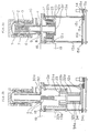
- Fig.2 shows another embodiment of the present invention. This embodiment differs from the embodiment shown in Fig.1, in that two bellows are utilized. Likewise the apparatus of Fig.1, a supporting stand comprising of a
cylinder section 34a and aflange 34b is provided below the sealingflange 8, and theflange 34b is mounted on a firstmovable member 12a having anopening 12a'. The firstmovable member 12a can be elevated by rotating afirst feed screw 13a, as same as in Fig.1. - A
first bellows 22a, which has a small diameter and of which lower end is gastightly mounted on theflange 34b, is arranged around thecylinder section 34a of the supportingstand 34. Cylindrical connecting means are positioned outside thebellows 22a, and the upper end of thefirst bellows 22a is gastightly mounted on a first flange 23a extended inwardly in radial direction in the upper end of the connectingmeans 23. - The lower end of the connecting
means 23 has aflange 23b extending outwardly in the radial direction, and theflange 23b has a hole to screw asecond feed screw 13b similar to the first feed screw 13'a and is gastightly mounted on a secondmovable member 12b which is elevated by rotating asecond feed screw 13b. The secondmovable member 12b has also a central opening section capable of communicating thefirst bellows 22a. - A
second bellows 22b, of which diameter is larger size than the connectingmeans 23, is gastightly mounted between a lower end of anintermediate chamber 17 and theflange 23b of the connectingmeans 23 and surrounding the connectingmeans 23. As mentioned above, by nesting two bellows of which lengths are almost the same, the whole length of the bellows can be reduced. Also, comparing with the bellows of the embodiment of Fig.1, the amount of expansion of each bellows is small, and the life of the bellows can be extended thereby. - As an alternative of this embodiment, the diameter of the first bellows may be larger and the diameter of the second bellows may be smaller. Also, although the whole length is longer, the diameters of two bellows may be set in equal, and they can be connected by the connecting means.
- Accordingly, the load lock chamber is formed by the first and the second bellows so that the boat table 6 and the supporting
boat 5 are isolated from the exterior. - Supposing that a diameter of a
pulley 15c provided below thefeed screw 13a is set in one half of a diameter of apulley 15d provided below thefeed screw 13b, each pulley is connected by abelt 16b and a rotation of themotor 14 is transferred to each feed screw, then a traveling speed of the firstmovable member 12a is twice a traveling speed of the secondmovable member 12b, so that two bellows can be expanded in the same amount as shown in Fig.2b. - Although it has been exampled that the diameters of two pulleys are adjusted, the expansions of the bellows can be done in the same amount by changing a screw pitch of each feed screw or by providing motor means for rotating each feed screw to adjust the rotation of each of the motor means.
- Although the elevation of the movable member has been performed by a feed screw in two embodiments mentioned above, such elevation may be done by elevating means such as air or oil cylinder in stead of the feed screw.
- The load lock chamber for a vertical type heat treatment apparatus of the present invention provides means for elevating a boat table supporting objects in the exterior thereof, and the load lock chamber is always maintained in gastight and is not contaminated by particles caused by the elevation thereby.
- Moreover, the load lock chamber is made of a flexible member such as a bellows and the elevating means are provided in the exterior, and the volume of the chamber can be reduced thereby.
- Furthermore, the sealing flange mounted on the boat table is under atmospheric air condition, and the boat table, that is objects, can easily be rotated by accessing a mechanism for rotating the boat table from the exterior thereby.
Claims (4)
- A load lock chamber which can be freely expanded in vertical and is arranged below a treatment chamber of a vertical type heat treatment apparatus, said load lock chamber being able to gastightly load supporting means for supporting objects into said apparatus and unload the supporting means from the apparatus through the lower part of said apparatus, characterized in that:
said load lock chamber is expanded by elevating means provided outside said load lock chamber and said supporting means is mounted in said load lock chamber. - A load lock chamber according to claim 1, wherein said load lock chamber is a metal bellows, said elevating means comprising of: a feed screw; a movable member, said movable member being screwed by said feed screw and engaged with said load lock chamber; and means for rotating said feed screw.
- A load lock chamber, which can be vertically freely expanded and is arranged below a treatment chamber of a vertical type heat treatment apparatus, said load lock chamber being able to gastightly load supporting means for supporting objects into said apparatus and unload the supporting means from the apparatus through the lower part of said apparatus, characterized in that:
said load lock chamber is comprised of an upper and a lower chamber sections, of which sizes are different, and which are connected in vertical, and said load lock chamber is expanded by elevating means provided outside said load lock chamber and said supporting means are mounted in said lower chamber section. - A load lock chamber according to claim 3, wherein said upper and said lower chamber sections are cylindrical metal bellows, said upper and said lower chamber sections being connected as a nest by connecting means, so that said elevating means are engaged with said lower chamber section and said connecting means.
Applications Claiming Priority (3)
| Application Number | Priority Date | Filing Date | Title |
|---|---|---|---|
| JP4327614A JP2548062B2 (en) | 1992-11-13 | 1992-11-13 | Load lock chamber for vertical heat treatment equipment |
| JP327614/92 | 1992-11-13 | ||
| PCT/JP1993/001660 WO1994011898A1 (en) | 1992-11-13 | 1993-11-12 | Load lock chamber for vertical type heat treatment apparatus |
Publications (2)
| Publication Number | Publication Date |
|---|---|
| EP0623948A1 true EP0623948A1 (en) | 1994-11-09 |
| EP0623948A4 EP0623948A4 (en) | 1995-04-12 |
Family
ID=18201025
Family Applications (1)
| Application Number | Title | Priority Date | Filing Date |
|---|---|---|---|
| EP93924820A Withdrawn EP0623948A4 (en) | 1992-11-13 | 1993-11-12 | Load lock chamber for vertical type heat treatment apparatus. |
Country Status (5)
| Country | Link |
|---|---|
| US (1) | US5571330A (en) |
| EP (1) | EP0623948A4 (en) |
| JP (1) | JP2548062B2 (en) |
| KR (1) | KR100361789B1 (en) |
| WO (1) | WO1994011898A1 (en) |
Cited By (2)
| Publication number | Priority date | Publication date | Assignee | Title |
|---|---|---|---|---|
| EP1208047A1 (en) * | 1999-08-05 | 2002-05-29 | S. C. Fluids, Inc. | Inverted pressure vessel with horizontal through loading |
| EP1358021A1 (en) * | 2000-08-04 | 2003-11-05 | S. C. Fluids, Inc. | Inverted pressure vessel with shielded closure mechanism |
Families Citing this family (35)
| Publication number | Priority date | Publication date | Assignee | Title |
|---|---|---|---|---|
| KR100244041B1 (en) * | 1995-08-05 | 2000-02-01 | 엔도 마코토 | Substrate processing apparatus |
| JP3971810B2 (en) * | 1995-11-30 | 2007-09-05 | 三星電子株式会社 | Vertical diffusion furnace |
| TW344847B (en) * | 1996-08-29 | 1998-11-11 | Tokyo Electron Co Ltd | Substrate treatment system, substrate transfer system, and substrate transfer method |
| US6082949A (en) * | 1996-10-11 | 2000-07-04 | Asyst Technologies, Inc. | Load port opener |
| TW539918B (en) * | 1997-05-27 | 2003-07-01 | Tokyo Electron Ltd | Removal of photoresist and photoresist residue from semiconductors using supercritical carbon dioxide process |
| US6106634A (en) * | 1999-02-11 | 2000-08-22 | Applied Materials, Inc. | Methods and apparatus for reducing particle contamination during wafer transport |
| US6334266B1 (en) | 1999-09-20 | 2002-01-01 | S.C. Fluids, Inc. | Supercritical fluid drying system and method of use |
| US6508259B1 (en) * | 1999-08-05 | 2003-01-21 | S.C. Fluids, Inc. | Inverted pressure vessel with horizontal through loading |
| US6497239B2 (en) | 1999-08-05 | 2002-12-24 | S. C. Fluids, Inc. | Inverted pressure vessel with shielded closure mechanism |
| US6748960B1 (en) | 1999-11-02 | 2004-06-15 | Tokyo Electron Limited | Apparatus for supercritical processing of multiple workpieces |
| CN1175470C (en) | 1999-11-02 | 2004-11-10 | 东京威力科创股份有限公司 | Method and apparatus for supercritical processing of multiple workpieces |
| US7018504B1 (en) | 2000-09-11 | 2006-03-28 | Asm America, Inc. | Loadlock with integrated pre-clean chamber |
| KR100345304B1 (en) * | 2000-10-12 | 2002-07-25 | 한국전자통신연구원 | Apparatus for perpendicular-type ultra vacuum chemical vapor deposition |
| JP2002359237A (en) * | 2001-05-30 | 2002-12-13 | Hitachi Kokusai Electric Inc | Manufacturing method of substrate treatment apparatus and semiconductor device |
| US6899507B2 (en) * | 2002-02-08 | 2005-05-31 | Asm Japan K.K. | Semiconductor processing apparatus comprising chamber partitioned into reaction and transfer sections |
| US7001468B1 (en) | 2002-02-15 | 2006-02-21 | Tokyo Electron Limited | Pressure energized pressure vessel opening and closing device and method of providing therefor |
| US20070243317A1 (en) * | 2002-07-15 | 2007-10-18 | Du Bois Dale R | Thermal Processing System and Configurable Vertical Chamber |
| US6722642B1 (en) | 2002-11-06 | 2004-04-20 | Tokyo Electron Limited | High pressure compatible vacuum chuck for semiconductor wafer including lift mechanism |
| US7021635B2 (en) | 2003-02-06 | 2006-04-04 | Tokyo Electron Limited | Vacuum chuck utilizing sintered material and method of providing thereof |
| US7077917B2 (en) | 2003-02-10 | 2006-07-18 | Tokyo Electric Limited | High-pressure processing chamber for a semiconductor wafer |
| JP4493955B2 (en) * | 2003-09-01 | 2010-06-30 | 東京エレクトロン株式会社 | Substrate processing apparatus and transfer case |
| US7767145B2 (en) | 2005-03-28 | 2010-08-03 | Toyko Electron Limited | High pressure fourier transform infrared cell |
| US7789971B2 (en) | 2005-05-13 | 2010-09-07 | Tokyo Electron Limited | Treatment of substrate using functionalizing agent in supercritical carbon dioxide |
| KR101522725B1 (en) * | 2006-01-19 | 2015-05-26 | 에이에스엠 아메리카, 인코포레이티드 | High Temperature ALD Inlet Manifold |
| DE102007063363B4 (en) * | 2007-05-21 | 2016-05-12 | Centrotherm Photovoltaics Ag | Device for doping and coating semiconductor material at low pressure |
| US8440048B2 (en) * | 2009-01-28 | 2013-05-14 | Asm America, Inc. | Load lock having secondary isolation chamber |
| US9574268B1 (en) | 2011-10-28 | 2017-02-21 | Asm America, Inc. | Pulsed valve manifold for atomic layer deposition |
| US9388492B2 (en) | 2011-12-27 | 2016-07-12 | Asm America, Inc. | Vapor flow control apparatus for atomic layer deposition |
| KR101557016B1 (en) * | 2013-10-17 | 2015-10-05 | 주식회사 유진테크 | Apparatus for processing substrate |
| JP6208588B2 (en) * | 2014-01-28 | 2017-10-04 | 東京エレクトロン株式会社 | Support mechanism and substrate processing apparatus |
| US10662527B2 (en) | 2016-06-01 | 2020-05-26 | Asm Ip Holding B.V. | Manifolds for uniform vapor deposition |
| US11492701B2 (en) | 2019-03-19 | 2022-11-08 | Asm Ip Holding B.V. | Reactor manifolds |
| KR20210048408A (en) | 2019-10-22 | 2021-05-03 | 에이에스엠 아이피 홀딩 비.브이. | Semiconductor deposition reactor manifolds |
| KR102245429B1 (en) * | 2020-06-08 | 2021-04-28 | 경상국립대학교산학협력단 | Manufacturing device for tube with porous layer for heat and mass transfer and manufacturing method thereof |
| US20230095095A1 (en) * | 2021-09-27 | 2023-03-30 | Applied Materials, Inc. | Method of isolating the chamber volume to process volume with internal wafer transfer capability |
Citations (1)
| Publication number | Priority date | Publication date | Assignee | Title |
|---|---|---|---|---|
| WO1991005887A1 (en) * | 1989-10-18 | 1991-05-02 | Varian Associates, Inc. | Vacuum vessel |
Family Cites Families (20)
| Publication number | Priority date | Publication date | Assignee | Title |
|---|---|---|---|---|
| JPS58149188A (en) * | 1982-02-26 | 1983-09-05 | 神鋼電機株式会社 | Conveying robot |
| JPS62113420A (en) * | 1985-11-12 | 1987-05-25 | Sumitomo Metal Ind Ltd | Plasma equipment |
| JPH0727875B2 (en) * | 1986-02-27 | 1995-03-29 | 株式会社ディスコ | Method for loading / unloading semiconductor substrate into / from vertical semiconductor heat treatment apparatus and apparatus for preventing outside air contamination |
| JPH0770495B2 (en) * | 1986-11-19 | 1995-07-31 | 東京エレクトロン株式会社 | Heat treatment equipment |
| JPS63312502A (en) * | 1987-06-12 | 1988-12-21 | Okuda Yasuyuki | Movable mechanism by multiple seal bellows |
| JPS647517A (en) * | 1987-06-29 | 1989-01-11 | Nec Corp | Heat treatment device for semiconductor substrate |
| JP2701847B2 (en) * | 1987-09-09 | 1998-01-21 | 東京エレクトロン株式会社 | Heat treatment method for semiconductor wafer |
| US5156521A (en) * | 1987-10-15 | 1992-10-20 | Epsilon Technology, Inc. | Method for loading a substrate into a GVD apparatus |
| JPH01125821A (en) * | 1987-11-10 | 1989-05-18 | Matsushita Electric Ind Co Ltd | Vapor growth device |
| US5088444A (en) * | 1989-03-15 | 1992-02-18 | Kabushiki Kaisha Toshiba | Vapor deposition system |
| US5127365A (en) * | 1990-02-27 | 1992-07-07 | Kabushiki Kaisha Toshiba | Vertical heat-treatment apparatus for semiconductor parts |
| FR2673918B1 (en) * | 1991-03-14 | 1993-05-28 | Houzay Francoise | AUTONOMOUS CONTAINER FOR THE VACUUM PROCESSING OF AN OBJECT, AND ITS TRANSFER SAS. |
| JP3181308B2 (en) * | 1991-04-03 | 2001-07-03 | 東京エレクトロン株式会社 | Heat treatment equipment |
| JP3140096B2 (en) * | 1991-07-11 | 2001-03-05 | 東京エレクトロン株式会社 | Heat treatment equipment |
| FR2682047B1 (en) * | 1991-10-07 | 1993-11-12 | Commissariat A Energie Atomique | GAS PHASE CHEMICAL PROCESSING REACTOR. |
| JP3281018B2 (en) * | 1992-01-27 | 2002-05-13 | 東京エレクトロン株式会社 | Heat treatment method |
| JPH0653302A (en) * | 1992-07-30 | 1994-02-25 | Fujitsu Ltd | Evacuating device |
| JPH06120159A (en) * | 1992-10-07 | 1994-04-28 | Kokusai Electric Co Ltd | Load lock-type longitudinal cvd-diffuser |
| JP3134137B2 (en) * | 1993-01-13 | 2001-02-13 | 東京エレクトロン株式会社 | Vertical processing equipment |
| JP3218488B2 (en) * | 1993-03-16 | 2001-10-15 | 東京エレクトロン株式会社 | Processing equipment |
-
1992
- 1992-11-13 JP JP4327614A patent/JP2548062B2/en not_active Expired - Fee Related
-
1993
- 1993-11-12 WO PCT/JP1993/001660 patent/WO1994011898A1/en not_active Application Discontinuation
- 1993-11-12 US US08/256,504 patent/US5571330A/en not_active Expired - Lifetime
- 1993-11-12 EP EP93924820A patent/EP0623948A4/en not_active Withdrawn
- 1993-11-12 KR KR1019940702406A patent/KR100361789B1/en not_active IP Right Cessation
Patent Citations (1)
| Publication number | Priority date | Publication date | Assignee | Title |
|---|---|---|---|---|
| WO1991005887A1 (en) * | 1989-10-18 | 1991-05-02 | Varian Associates, Inc. | Vacuum vessel |
Non-Patent Citations (1)
| Title |
|---|
| See also references of WO9411898A1 * |
Cited By (4)
| Publication number | Priority date | Publication date | Assignee | Title |
|---|---|---|---|---|
| EP1208047A1 (en) * | 1999-08-05 | 2002-05-29 | S. C. Fluids, Inc. | Inverted pressure vessel with horizontal through loading |
| EP1208047A4 (en) * | 1999-08-05 | 2004-03-31 | S C Fluids Inc | Inverted pressure vessel with horizontal through loading |
| EP1358021A1 (en) * | 2000-08-04 | 2003-11-05 | S. C. Fluids, Inc. | Inverted pressure vessel with shielded closure mechanism |
| EP1358021A4 (en) * | 2000-08-04 | 2004-03-31 | S C Fluids Inc | Inverted pressure vessel with shielded closure mechanism |
Also Published As
| Publication number | Publication date |
|---|---|
| US5571330A (en) | 1996-11-05 |
| JPH06151559A (en) | 1994-05-31 |
| KR100361789B1 (en) | 2003-03-26 |
| JP2548062B2 (en) | 1996-10-30 |
| WO1994011898A1 (en) | 1994-05-26 |
| EP0623948A4 (en) | 1995-04-12 |
Similar Documents
| Publication | Publication Date | Title |
|---|---|---|
| EP0623948A1 (en) | Load lock chamber for vertical type heat treatment apparatus | |
| US6254328B1 (en) | High vacuum dual stage load lock and method for loading and unloading wafers using a high vacuum dual stage load lock | |
| US5520743A (en) | Processing apparatus with means for rotating an object mounting means and a disk body located in the mounting means differently relative to each other | |
| JP7330181B2 (en) | High-pressure steam annealing treatment equipment | |
| JP2018056232A (en) | Gas introduction mechanism and processing device | |
| US6352403B1 (en) | Controlled environment enclosure and mechanical interface | |
| KR20030002299A (en) | Substrate processing apparatus, substrate processing method, semiconductor device fabricating method, and conveying unit | |
| WO1996025760A1 (en) | Method and device for manufacturing semiconductor | |
| KR20040094670A (en) | Vertical heat treating equipment | |
| KR20190034093A (en) | Substrate processing method and substrate processing apparatus | |
| KR100666018B1 (en) | Processing apparatus and processing method | |
| KR20030074255A (en) | Substrate processing apparatus and substrate processing method | |
| WO2004090959A1 (en) | Method of heat treatment and heat treatment apparatus | |
| US6852601B2 (en) | Heat treatment method that includes a low negative pressure | |
| US9716021B2 (en) | Substrate heat treatment apparatus, method of installing substrate heat treatment apparatus | |
| US5671903A (en) | Heat treatment apparatus and valve device for use in the same | |
| US7640946B2 (en) | Vacuum treating device with lidded treatment container | |
| US20020182870A1 (en) | Substrate processing apparatus and a method for fabricating a semiconductor device by using same | |
| US6954585B2 (en) | Substrate processing method and apparatus | |
| US6168427B1 (en) | Apparatus for guiding the removal of a processing tube from a semiconductor furnace | |
| US6538237B1 (en) | Apparatus for holding a quartz furnace | |
| US20200102652A1 (en) | Injector and substrate processing appartatus using the same, and substrate processing method | |
| US7361595B2 (en) | Transition metal thin film forming method | |
| JP4278407B2 (en) | Substrate processing apparatus and substrate processing method | |
| JP2668020B2 (en) | Semiconductor manufacturing equipment |
Legal Events
| Date | Code | Title | Description |
|---|---|---|---|
| PUAI | Public reference made under article 153(3) epc to a published international application that has entered the european phase |
Free format text: ORIGINAL CODE: 0009012 |
|
| 17P | Request for examination filed |
Effective date: 19940809 |
|
| AK | Designated contracting states |
Kind code of ref document: A1 Designated state(s): DE FR GB NL |
|
| A4 | Supplementary search report drawn up and despatched | ||
| AK | Designated contracting states |
Kind code of ref document: A4 Designated state(s): DE FR GB NL |
|
| 17Q | First examination report despatched |
Effective date: 19960821 |
|
| STAA | Information on the status of an ep patent application or granted ep patent |
Free format text: STATUS: THE APPLICATION IS DEEMED TO BE WITHDRAWN |
|
| 18D | Application deemed to be withdrawn |
Effective date: 19990601 |