EP0623472B1 - Ink jet printing system - Google Patents
Ink jet printing system Download PDFInfo
- Publication number
- EP0623472B1 EP0623472B1 EP94302528A EP94302528A EP0623472B1 EP 0623472 B1 EP0623472 B1 EP 0623472B1 EP 94302528 A EP94302528 A EP 94302528A EP 94302528 A EP94302528 A EP 94302528A EP 0623472 B1 EP0623472 B1 EP 0623472B1
- Authority
- EP
- European Patent Office
- Prior art keywords
- ink
- printhead
- pressure
- orifices
- reservoir
- Prior art date
- Legal status (The legal status is an assumption and is not a legal conclusion. Google has not performed a legal analysis and makes no representation as to the accuracy of the status listed.)
- Expired - Lifetime
Links
- 238000007641 inkjet printing Methods 0.000 title claims description 13
- 239000012943 hotmelt Substances 0.000 claims description 10
- 230000015556 catabolic process Effects 0.000 claims description 7
- 238000006731 degradation reaction Methods 0.000 claims description 7
- 238000007639 printing Methods 0.000 claims description 7
- 238000010438 heat treatment Methods 0.000 claims description 5
- 230000008018 melting Effects 0.000 claims description 3
- 238000002844 melting Methods 0.000 claims description 3
- 229920001169 thermoplastic Polymers 0.000 claims description 2
- 239000004416 thermosoftening plastic Substances 0.000 claims description 2
- 238000005086 pumping Methods 0.000 claims 2
- 230000002401 inhibitory effect Effects 0.000 claims 1
- 239000000976 ink Substances 0.000 description 179
- XLYOFNOQVPJJNP-UHFFFAOYSA-N water Substances O XLYOFNOQVPJJNP-UHFFFAOYSA-N 0.000 description 15
- 239000012530 fluid Substances 0.000 description 6
- 238000010926 purge Methods 0.000 description 6
- 239000007788 liquid Substances 0.000 description 3
- 239000012528 membrane Substances 0.000 description 3
- 238000010586 diagram Methods 0.000 description 2
- 230000000694 effects Effects 0.000 description 2
- 239000007787 solid Substances 0.000 description 2
- 239000004793 Polystyrene Substances 0.000 description 1
- 239000004809 Teflon Substances 0.000 description 1
- 229920006362 Teflon® Polymers 0.000 description 1
- XAGFODPZIPBFFR-UHFFFAOYSA-N aluminium Chemical compound [Al] XAGFODPZIPBFFR-UHFFFAOYSA-N 0.000 description 1
- 229910052782 aluminium Inorganic materials 0.000 description 1
- 239000000356 contaminant Substances 0.000 description 1
- 230000008602 contraction Effects 0.000 description 1
- 238000001816 cooling Methods 0.000 description 1
- 230000003247 decreasing effect Effects 0.000 description 1
- 230000001419 dependent effect Effects 0.000 description 1
- 238000007599 discharging Methods 0.000 description 1
- 230000005284 excitation Effects 0.000 description 1
- 238000010030 laminating Methods 0.000 description 1
- 239000000463 material Substances 0.000 description 1
- 229920000193 polymethacrylate Polymers 0.000 description 1
- 229920005553 polystyrene-acrylate Polymers 0.000 description 1
- 238000007789 sealing Methods 0.000 description 1
- 230000008023 solidification Effects 0.000 description 1
- 238000007711 solidification Methods 0.000 description 1
- 239000000758 substrate Substances 0.000 description 1
- 239000012780 transparent material Substances 0.000 description 1
Images


Classifications
-
- B—PERFORMING OPERATIONS; TRANSPORTING
- B41—PRINTING; LINING MACHINES; TYPEWRITERS; STAMPS
- B41J—TYPEWRITERS; SELECTIVE PRINTING MECHANISMS, i.e. MECHANISMS PRINTING OTHERWISE THAN FROM A FORME; CORRECTION OF TYPOGRAPHICAL ERRORS
- B41J25/00—Actions or mechanisms not otherwise provided for
- B41J25/304—Bodily-movable mechanisms for print heads or carriages movable towards or from paper surface
-
- B—PERFORMING OPERATIONS; TRANSPORTING
- B41—PRINTING; LINING MACHINES; TYPEWRITERS; STAMPS
- B41J—TYPEWRITERS; SELECTIVE PRINTING MECHANISMS, i.e. MECHANISMS PRINTING OTHERWISE THAN FROM A FORME; CORRECTION OF TYPOGRAPHICAL ERRORS
- B41J2/00—Typewriters or selective printing mechanisms characterised by the printing or marking process for which they are designed
- B41J2/005—Typewriters or selective printing mechanisms characterised by the printing or marking process for which they are designed characterised by bringing liquid or particles selectively into contact with a printing material
- B41J2/01—Ink jet
- B41J2/17—Ink jet characterised by ink handling
- B41J2/175—Ink supply systems ; Circuit parts therefor
-
- B—PERFORMING OPERATIONS; TRANSPORTING
- B41—PRINTING; LINING MACHINES; TYPEWRITERS; STAMPS
- B41J—TYPEWRITERS; SELECTIVE PRINTING MECHANISMS, i.e. MECHANISMS PRINTING OTHERWISE THAN FROM A FORME; CORRECTION OF TYPOGRAPHICAL ERRORS
- B41J2/00—Typewriters or selective printing mechanisms characterised by the printing or marking process for which they are designed
- B41J2/005—Typewriters or selective printing mechanisms characterised by the printing or marking process for which they are designed characterised by bringing liquid or particles selectively into contact with a printing material
- B41J2/01—Ink jet
- B41J2/17—Ink jet characterised by ink handling
- B41J2/175—Ink supply systems ; Circuit parts therefor
- B41J2/17593—Supplying ink in a solid state
-
- B—PERFORMING OPERATIONS; TRANSPORTING
- B41—PRINTING; LINING MACHINES; TYPEWRITERS; STAMPS
- B41J—TYPEWRITERS; SELECTIVE PRINTING MECHANISMS, i.e. MECHANISMS PRINTING OTHERWISE THAN FROM A FORME; CORRECTION OF TYPOGRAPHICAL ERRORS
- B41J2/00—Typewriters or selective printing mechanisms characterised by the printing or marking process for which they are designed
- B41J2/005—Typewriters or selective printing mechanisms characterised by the printing or marking process for which they are designed characterised by bringing liquid or particles selectively into contact with a printing material
- B41J2/01—Ink jet
- B41J2/17—Ink jet characterised by ink handling
- B41J2/19—Ink jet characterised by ink handling for removing air bubbles
-
- B—PERFORMING OPERATIONS; TRANSPORTING
- B41—PRINTING; LINING MACHINES; TYPEWRITERS; STAMPS
- B41J—TYPEWRITERS; SELECTIVE PRINTING MECHANISMS, i.e. MECHANISMS PRINTING OTHERWISE THAN FROM A FORME; CORRECTION OF TYPOGRAPHICAL ERRORS
- B41J2/00—Typewriters or selective printing mechanisms characterised by the printing or marking process for which they are designed
- B41J2/005—Typewriters or selective printing mechanisms characterised by the printing or marking process for which they are designed characterised by bringing liquid or particles selectively into contact with a printing material
- B41J2/01—Ink jet
- B41J2/17—Ink jet characterised by ink handling
- B41J2/195—Ink jet characterised by ink handling for monitoring ink quality
Definitions
- This invention relates to ink jet printing apparatus and, more particularly, to a new and improved ink jet printer having a printhead capable of ink jet printing in different orientations and relative positions.
- Ink jet printing systems include a printhead having small orifices through which ink is ejected in a controlled manner to form an image on an adjacent substrate.
- the ink in the printhead must be maintained at a selected negative pressure which is dependent upon the orifice size and the ink characteristics and may be, for example, about 2 to 3 inches of water.
- ink jet printing systems having a remote ink supply connected to the printhead through a supply line, however, the pressure of the ink in the printhead can be affected by the relative vertical positions of the printhead and the remote ink supply.
- many ink jet printers are designed to operate only in one orientation of the printhead, which limits the manner in which the ink jet system can be used.
- U.S. Patent No. 4651161 is concerned with the problem of causing a "drop on demand" ink jet printer to eject drops of constant volume despite changes in time elapsing between successive actuation.
- a circuit is provided which varies the pressure of writing fluid, such as pigmented ink, supplied to the ink jet printer head in response to timing pulses from a controller or other device in which circuit the timing pulses are associated with the instantaneous actuation frequency of the printer head and correspond to the desired ink pressure at the head required to eject ink drops of consistent volume.
- Ink is supplied to the ink jet head from a fluid chamber having pressure producing means for changing the pressure of the ink in the chamber and ink is fed to the chamber under pressure from an ink source.
- a pressure sensor is located between the fluid chamber and the ink jet head and senses the pressure of ink at the head.
- the sensor produces a signal representative of the sensed pressure at the head and the sensed pressure is compared to the desired pressure to produce a pressure modulating signal.
- the pressure modulating signal is used to excite drive means coupled to the fluid chamber pressure producing means to vary the pressure of ink in the fluid chamber.
- the fluid chamber ink pressure is related to the actuation frequency and changes in the actuation frequency produce corresponding changes in the chamber ink pressure to supply ink to the ink jet head at the desired pressure.
- U.S. Patent No. 4700205 is concerned with the problem of causing a "drop-on-demand" ink jet printer to eject drops at constant volume and velocity over a wide range of actuation frequencies.
- a hydraulic servomechanism is provided for controlling the pressure of ink supplied to the ink jet printer head from an ink source.
- a bellows is coupled between the ink source and the ink jet printer head and includes an inlet for receiving the ink and an outlet for discharging the ink. The bellows is arranged for expansion and contraction for increasing and decreasing its volume to decrease and increase respectively the pressure of the ink contained within the bellows.
- the inlet includes a valve for permitting ink to flow into the bellows when the valve is operated to its open condition and for preventing ink from entering the bellows when it is operated to its closed condition.
- the outlet includes a pressure sensor for sensing the pressure of the ink supplied to the ink jet printer head and produces a signal having a magnitude proportional to the sensed pressure.
- Comparator means is provided for comparing the sensed ink pressure to a desired ink pressure and the difference between the two pressures produces a driving signal.
- Excitation means coupled to the bellows is responsive to the driving signal and exerts a force on the bellows to expand or contract the bellows to decrease or increase the pressure of the ink in the bellows whereby the ink is supplied to the ink jet head at the desired pressure.
- Means is also provided for maintaining the volume of ink in the bellows within a predetermined volumetric range and includes means for operating the valve to its open condition when the ink volume is at a minimum desired volume and to its closed condition when the ink volume is at its maximum desired volume.
- An object of the invention is to provide ink jet printing apparatus having a printhead which can be operated in any desired orientation or any vertical position with respect to a remote ink supply.
- hot melt ink which is solid at room temperature and becomes liquid at elevated temperatures
- the ink is ejected from the printhead at a relatively high temperature which is sufficient to ensure low enough viscosity of the ink for the desired operation.
- Such hot melt inks tend to deteriorate when maintained at high temperature, which tends to limit the usefulness of hot melt ink jet printing systems.
- the temperature of hot melt ink is controlled so as to inhibit degradation by separately controlling the temperature of ink in a remote ink supply, in the supply line, in an ink reservoir on the printhead, and in passages leading from the printhead reservoir to the ink jet orifices so that only the ink in the passages leading to the orifices is maintained at the temperature required for jetting, while the temperature of the ink in the other portions of the system is maintained at appropriate lower levels to reduce the risk of degradation.
- the pressure of the ink in the printhead is selectively controlled at any of a plurality of different pressure levels by providing an air pressure control system capable of producing any of a plurality of positive and negative air pressure levels for selective connection to the printhead to control the pressure of the ink therein at a desired negative level during printing and also to provide a desired positive pressure to the ink in the ink jet head for purging purposes.
- the supply from the remote reservoir to the printhead includes a check valve requiring at least a selected minimum pressure at least equal to the pressure corresponding to the maximum elevational distance between the remote reservoir and the printhead, such as 5 psi, to be applied to transfer ink to the printhead.
- the pressure control system of the present invention may be arranged to apply different pressures to each of the printhead reservoirs.
- air is drawn by a vacuum pump through flow paths of uniform cross-section, such as grooves in the surface of a covered plate having different lengths and thereby producing different negative pressure levels, and each of those paths is selectively connectable to the ink reservoirs in the printhead to provide a controlled negative pressure therein.
- the pressure control unit may be tested for leaks by determining the pump duty cycle required to produce a selected pressure level and comparing it with a predetermined duty cycle.
- a main control unit 10 includes a remote ink supply reservoir 12 connected through an ink supply conduit 14 in a cable 15 to an ink jet printhead 16 and a pressure control unit 18 connected to the ink jet printhead 16 through three air conduits 19, 84 and 86, also carried by the cable 15.
- the main control unit 10 includes a temperature control unit 22 for controlling the temperature of hot melt ink in various portions of the ink jet system in a manner to be described hereinafter.
- the printhead 16 is movably supported on a vertically disposed column 24 so as to be locked by a clamp 26 at any desired vertical position on the column.
- the printhead 16 is supported for pivotal motion in any vertical plane by a clampable universal joint 28 so that the printhead can be oriented to permit a linear array of ink jet orifices 30 therein, best seen in Fig. 2, to project ink horizontally, either in a horizontal line or in a vertical line, or downwardly.
- the printhead is disposed in a horizontal orientation as shown in solid lines to cause the printhead orifices 30 (shown in Fig. 2) to project a train of ink drops 31 downwardly onto the top surfaces 32 of a series of containers 34 which are conveyed in the horizontal direction by a conveyor 36, thus permitting appropriate information to be printed on the top surface of each of the containers.
- the printhead can be lowered on the column 24 and the universal joint 28 can be arranged to clamp the head 16 in a sidewise orientation with the array of orifices 30 extending vertically and facing the near sides 37 of the containers 34, as viewed in the drawing, so as to cause information to be printed on the sides of each of the containers as they are conveyed past the printhead by the conveyor 36.
- the printing system of the invention may be arranged to print a series of labels 38 conveyed on a tape 40 in a vertical direction from one reel 42 to another reel 44 by adjusting the universal joint 28 to clamp the printhead in a vertical orientation, as shown in dotted outline in Fig. 1, so that the array of orifices 30 extends horizontally and faces the labels 38 as they are conveyed in the vertical direction.
- the temperature control unit 22 is arranged to control the heater 50 so as to heat the block of hot melt ink 48 sufficiently to melt it and to maintain the ink in the supply reservoir 12 at a temperature just above its melting point so that it is sufficiently liquid that it can be transferred by a pump 53 through the supply conduit 14 to the printhead 16 as required.
- the ink temperature in the supply reservoir 12 is kept low enough so that no appreciable degradation will take place even though the ink is maintained continuously at that temperature for several days or weeks.
- the ink supply conduit 14 contains a thermostatically controlled heater 54 connected through a line 56 to the temperature control unit 22 so that the ink in the supply line is also maintained continuously in liquid condition, but at a temperature low enough that no appreciable degradation occurs.
- the printhead 16 includes two ink reservoirs 58 and 60 containing ink at different levels, a passage 62 leading from the high level reservoir 58 to a deaerator 64 and another passage 66 leading from the low level reservoir to the deaerator 64.
- the passages 62 and 66 pass downwardly as viewed in Figs. 2 and 3 in the deaerator 64 adjacent to a membrane 68 which separates those passages from a vacuum chamber 70 connected to the vacuum line 19 from the pressure control unit 18. That line and the chamber 70 are maintained at a pressure level of about 25 in.Hg.
- the ink passages 62 and 66 extend downwardly to supply alternately adjacent orifices 30 respectively in the array, ink from the low level reservoir being supplied through a passage 72 shown in Fig. 2 which extends downwardly adjacent to an orifice plate 74 to supply alternate odd-numbered orifices in the array, and ink from the high level reservoir being supplied downwardly to the bottom of the orifice plate 74 and upwardly adjacent to the orifice plate to the alternate even-numbered orifices 30 through a passage 73 illustrated in dotted line in Fig. 3.
- Each of the orifices 30 in the printhead 16 has an associated transducer 76 arranged to respond to electrical signals to eject ink drops through the corresponding orifice in the usual manner, as described, for example, in US-A-4,584,590.
- An appropriate arrangement of the ink passages 72 and 73, transducers 76, orifices 30 and supply passages 62 and 66 is described in detail in US-A- 4,835,554.
- a heater 78 is mounted in the printhead adjacent to the passages 72 and 73 and is connected through a line 79 in the cable 15 to the temperature control unit 22.
- a further heater 80 is mounted adjacent to the reservoirs 58 and 60 and is connected to the control unit 22 by a line 81.
- the control unit is arranged to maintain the temperature of the ink in the reservoirs 58 and 60 at a temperature sufficiently below the jetting temperature to avoid degradation, but close enough to the jetting temperature to permit the orifice passage heater 78 to heat the ink quickly to the jetting temperature as the ink is supplied through the passages 72 and 73 to the orifices 30.
- the temperature control unit 22 may be arranged to maintain the temperature of the ink in the remote ink supply reservoir 12 and in the ink supply conduit 14 at a temperature of about 100°C and to control the heater 80 to maintain the ink in the reservoirs 58 and 60 at a temperature of about 125°C, but to control the heater 78 so as to maintain the ink in the passages 72 and 73 leading to the orifices 30 at a jetting temperature of 137°C. Since only a small quantity of ink is maintained in the passages 72 and 73 and, during operation, the ink passes through those passages relatively rapidly, no significant degradation of ink can occur during operation of the ink jet system.
- the temperature control unit 22 reduces the temperature of the ink in the passages 72 and 73 to a lower level, such as the 125°C temperature of the ink in the reservoirs 58 and 60. Moreover, if the capacity of the reservoirs 58 and 60 is small enough to permit rapid heating of the ink in those reservoirs to the normal 125°C operating temperature, the temperature control unit 22 can be arranged to maintain the ink in those reservoirs as well as in the orifice passageway 68 at an even lower temperature such as 120°C when the system is in the stand-by condition.
- the temperature control unit 22 is arranged to cause the ink in the reservoirs 58 and 60 and the deaerator 64 to be maintained in the molten condition until the ink in the passages 72 and 73 has solidified when the printing system is turned off, thereby preventing air from being drawn into those passages as the reservoir ink solidifies.
- the negative pressure normally applied to the reservoirs as described hereinafter may be terminated while the ink in the passages 72 and 73 is cooling to reduce the tendency of air to be drawn into the orifices 30.
- the ink supply conduit 14 leading from the remote ink supply reservoir 12 to the printhead includes a check valve 82 which is spring-biased toward the closed position with sufficient force to require an ink pressure of, for example, at least 5 psi to open the valve and permit ink to pass from the line 14 into the low level reservoir 60.
- the printhead pressure control unit 18 in the main control unit 10 is connected through two conduits 84 and 86 to the reservoirs 58 and 60, respectively, so that a negative air pressure of approximately 2.8 inches (7,1 cm) of water is normally maintained in those reservoirs.
- a negative air pressure of approximately 2.8 inches (7,1 cm) of water is normally maintained in those reservoirs.
- this pressure level produces a negative air pressure of about two inches (5 cm) at the orifices 30 which is sufficient to prevent ink from seeping out of the orifices as a result of capillary action, but is not low enough to cause air to be drawn into the passages 72 and 73 through the orifices 30, which would interfere with the operation of the system.
- each of the ink passages 72 and 73 is connected through a return flow path (not shown) to the ink passages 62 and 66 leading to the other of the two reservoirs 58 and 60.
- the pressure control unit 18 In order to restore the difference in the ink level in the reservoirs 58 and 60, the pressure control unit 18 periodically applies a higher negative pressure of about 3.2 inches (8,1 cm) of water through the line 84 to the ink in the reservoir 58, thereby drawing ink through a check valve 87 from the low level reservoir 60 to the high level reservoir 58 until the difference in the ink levels in the reservoirs balances the applied pressure difference.
- the ink jet system when the ink jet system is started up after being cold, for example after having been turned off overnight, it may be necessary to purge air bubbles and debris from the orifice passages 72 and 73 in order to assure proper operation of the system. This is accomplished by applying a positive pressure of about 2 psi through both of the lines 84 and 86, thereby forcing ink from both reservoirs through the orifice passages 68 and out of the orifices 30 to remove any air bubbles and debris which may be trapped in those passages.
- Fig. 4 illustrates the printhead 16 oriented in a position in which the array of orifices 30 extends in the vertical direction, such as to print information on the sides of the containers 34 as described above with reference to Fig. 1.
- the ink pressure will normally be less at the orifices supplied by the low level reservoir 60 than at the orifices supplied by the high level reservoir 58, the ink pressure will normally be less at the orifices, which could cause air to be drawn into the ink passages 72 receiving ink from the low level reservoir or produce seepage of ink at the orifices connected to the high level reservoir 58.
- the pressure control unit 18 is arranged to reduce the negative pressure applied to the high level reservoir while maintaining the desired negative pressure at the low level reservoir.
- a negative pressure of about 1.1 inches of water may be applied through the line 86 to the low level reservoir 60 while the usual negative pressure of about 2.8 inches of water is applied through the line 84 to the high level reservoir 58, providing a difference of about 1.7 inches of water between the negative pressures applied to the reservoirs to compensate for the difference in the height of the reservoirs as shown in Fig. 4 when the array is oriented in the vertical direction.
- Fig. 5 illustrates the printhead when positioned to project ink downwardly from the orifices 30, for example, to the top surfaces of the containers shown in Fig. 2.
- the two reservoirs are at the same elevation and the elevational difference between the reservoirs and the orifices is approximately the same as that of Figs. 2 and 3. Consequently, the same negative pressure of about 2.8 inches of water is applied to both reservoirs.
- a pump 90 has an air intake connected through a two-position valve 92 alternatively to a line 94 leading to an intake filter 96 or to a line 98 connected through a first restriction 100, an accumulator 102, a second restriction 104, and a second accumulator 106 and then to a line 108 leading to the filter 96 through a series of three successive restrictions 110, 112 and 114.
- Each of these restrictions may, for example, constitute a single needle valve or orifice or a number of needle valves or orifices in series or the restrictions may consist of continuous passages of constant reduced cross-sectional area providing flow resistance proportional to their length such as tubes or grooves, as described hereinafter, which avoids the possibility of clogging of orifices or valves.
- the pump 90 and the accumulators and restrictions are arranged so that a continuous flow of air is drawn through the filter 96 and the line 108 to provide substantially constant negative pressures of about 3.2 inches of water at a line 116 connected between the restriction 110 and the line 108, about 2.8 inches (7,1 cm) of water at a line 118 between the restrictions 110 and 112 and about 1.1 inches of water at a line 120 connected between the restrictions 112 and 114.
- a two-position valve 122 is arranged to selectively connect a line 124 either to the line 116 or to the line 118 and the line 124 is selectively connected through another two-position valve 126 to a line 128 which is, in turn, connected to the conduit 84 leading to the high level reservoir 58 in the printhead 16.
- the positive pressure side of the pump 90 is connected to a line 130 which opens to the atmosphere through a restriction 132 arranged to provide a constant positive air pressure of about 2 psi (0,16 kg/cm 2 ) at the pump output line 130.
- the valve 126 is moved to a position connecting the positive pressure line 130 through the line 128 and the conduit 84 to the high level reservoir to apply a purging pressure.
- another valve 134 is moved to a position connecting the line 128 to a line 136 connected to the conduit 86 leading to the low level reservoir 60 so that the 2 psi positive pressure is applied to both reservoirs at the same time.
- the ink in the orifice passageways 72 and 73 leading to the orifices 30 is ejected under pressure through the orifices, carrying with it any contaminants and air bubbles which may have accumulated.
- valves 126 and 134 are restored to the positions illustrated in Fig. 6, causing a negative pressure of about 2.8 inches of water to be applied from the line 118 and the line 124 through the line 128 and the conduit 84 to the high level ink reservoir and through a valve 140, the line 136 and the conduit 86 to the low level ink reservoir. With the array of orifices oriented in the horizontal direction, this negative pressure level is maintained during normal operation.
- valve 122 When the ink level in the high level reservoir has been reduced as a result of the continuous flow of ink through the orifice passageways from the high level reservoir to the low level reservoir as described above, the valve 122 is shifted to the other position, at which the line 116 is connected to the line 128 and the conduit 84 so as to apply a negative pressure of about 3.2 inches of water to the high level reservoir 58, thereby drawing ink from the low level reservoir 60 through the check valve 87 into the high level reservoir. When the desired high ink level in that reservoir has been restored, the valve 122 is returned to the position illustrated in Fig. 6. The rate of continuous flow of ink through the printhead from the high level reservoir to the low level reservoir is controlled by the orifice passageway restrictions 141 illustrated schematically in Fig. 6.
- the valve 140 is shifted to a position at which the line 120 is connected to the line 136, thereby applying a reduced negative pressure of about 1.1 inches of water through the conduit 86 to the lower reservoir 60 to counteract any tendency for air to be drawn into the orifice passages 72.
- the pressure control unit 18 includes a vacuum pump 142 generating a vacuum of about 25 in.Hg. which is connected through a line 144 to the conduit 19 leading to the vacuum chamber 70 adjacent to the membrane 68 in the deaerator 64 so as to extract dissolved air from the ink passing through the deaerator.
- the line 144 includes a vacuum sensor 146 to enable control of the vacuum produced by the pump 142 and applied to the line 144.
- a pressure sensor 150 is included in a line 152 connected between the lines 94 and 108 to permit control of the vacuum drawn by the pump 90 through the lines 98 and 108.
- a low ink sensor 153 detects a minimum level of ink in the low level reservoir 60 and initiates the transfer of ink by the pump 53 from the remote ink supply reservoir 12 through the conduit 14 and the check valve 82 to the low level printhead reservoir 60.
- each of the reservoirs includes a vacuum shield 154 at the openings connected to vacuum lines.
- These vacuum shields are made of Teflon or another material which is not wetted by the ink used in the system and they have a 0.016-inch opening at the end facing the ink in the reservoir leading to a 0.04-inch passage extending through the shield to the end connected to the vacuum line.
- the reservoirs may be oriented so that the ink is adjacent to the vacuum shields without causing the ink to flow through the vacuum shields to enter the conduits 84 and 86.
- the pressure control unit 18 is prevented from being contaminated with ink drawn into the vacuum line even though the printhead may have been oriented in such a way as to cause ink to flow against the openings leading to the vacuum lines while it is being mounted or transported.
- FIG. 7 A typical arrangement for providing various levels of negative and positive pressure in the pressure control unit 18 is illustrated in Fig. 7.
- an aluminum plate 156 having a flat upper surface is formed with a series of grooves having uniform depth of about 0.040 inch and a width of approximately 1/16th inch each so as to provide a predetermined uniform resistance to air flow through the grooves.
- the exposed surface of the plate is covered, for example, by a rigid thermoplastic sheet 158 which may be made of a rigid transparent material such as polystyrene or polymethacrylate laminated to the plate 156 so that the grooves are sealed by a flat surface at the surface of the plate.
- the total resistance to the flow of air through each groove is directly proportional to the length of the groove.
- larger grooves of, for example, 1/8th inch width and depth, are provided.
- the grooves providing the flow restrictions illustrated schematically in the diagram of Fig. 6 are designated by corresponding reference numerals and the other elements of the pressure control system shown in Fig. 6, such as the pump 90, the pressure sensor 150, the valves 92, 122, 126, 134 and 140, are also illustrated schematically in Fig. 7.
- desired pressure levels for a pressure control system can be provided accurately and conveniently by merely forming grooves of predetermined cross-section in the surface of a plate and making the relative lengths of the grooves proportional to the relative pressure differences required.
- the three restrictions 114, 112 and 110 connected in series may, for example, have lengths of 11 inches, 17 inches and 4 inches.
- laminating a rigid cover 158 to the plate 156 prevents any air leakage between the cover and the plate while also as-
- valves 126 and 134 are actuated so that the vacuum lines 116, 118 and 120 are disconnected from the lines 84 and 86 leading to the printhead 16 and the system is set to maintain a negative air pressure of, for example, 3.2 inches of water as detected by the sensor 150 between the intake filter 96 and the accumulator 106.
- the duty cycle for the pump 90 normally required to maintain the 3.2 inches negative air pressure may, for example, be about 33%. If the pump duty cycle is significantly different from such predetermined value when the lines 84 and 86 are reconnected by the valves 126 and 134, it will be evident that there is a leak in the system which could lead to faulty performance.
- the pump duty cycle required to maintain a 2 psi pressure in the lines 84 and 86 leading to the reservoirs 58 and 60 when the valves 126 and 134 are actuated and the printhead is cold so that the ink in the reservoirs is solidified should approximate a predetermined relatively low value, but the duty cycle should increase to a predetermined higher value when the printhead has been heated to melt the ink and permit the applied pressure to force the ink out of the printhead orifices 30 in a purging operation.
- leakage or blockage of the pressure supply system is indicated. In this way, the pressure control system can be tested conveniently in conjunction with the printhead after assembly.
Landscapes
- Engineering & Computer Science (AREA)
- Quality & Reliability (AREA)
- Ink Jet (AREA)
- Particle Formation And Scattering Control In Inkjet Printers (AREA)
Description
- This invention relates to ink jet printing apparatus and, more particularly, to a new and improved ink jet printer having a printhead capable of ink jet printing in different orientations and relative positions.
- Ink jet printing systems include a printhead having small orifices through which ink is ejected in a controlled manner to form an image on an adjacent substrate. To counteract the effect of capillary action in the small orifices which would otherwise cause ink to seep out of the printhead when not in use but, at the same time, prevent air from being drawn into the printhead through the orifices, the ink in the printhead must be maintained at a selected negative pressure which is dependent upon the orifice size and the ink characteristics and may be, for example, about 2 to 3 inches of water. In ink jet printing systems having a remote ink supply connected to the printhead through a supply line, however, the pressure of the ink in the printhead can be affected by the relative vertical positions of the printhead and the remote ink supply. Moreover, many ink jet printers are designed to operate only in one orientation of the printhead, which limits the manner in which the ink jet system can be used.
- U.S. Patent No. 4651161 is concerned with the problem of causing a "drop on demand" ink jet printer to eject drops of constant volume despite changes in time elapsing between successive actuation. A circuit is provided which varies the pressure of writing fluid, such as pigmented ink, supplied to the ink jet printer head in response to timing pulses from a controller or other device in which circuit the timing pulses are associated with the instantaneous actuation frequency of the printer head and correspond to the desired ink pressure at the head required to eject ink drops of consistent volume. Ink is supplied to the ink jet head from a fluid chamber having pressure producing means for changing the pressure of the ink in the chamber and ink is fed to the chamber under pressure from an ink source. A pressure sensor is located between the fluid chamber and the ink jet head and senses the pressure of ink at the head. The sensor produces a signal representative of the sensed pressure at the head and the sensed pressure is compared to the desired pressure to produce a pressure modulating signal. The pressure modulating signal is used to excite drive means coupled to the fluid chamber pressure producing means to vary the pressure of ink in the fluid chamber. The fluid chamber ink pressure is related to the actuation frequency and changes in the actuation frequency produce corresponding changes in the chamber ink pressure to supply ink to the ink jet head at the desired pressure.
- U.S. Patent No. 4700205 is concerned with the problem of causing a "drop-on-demand" ink jet printer to eject drops at constant volume and velocity over a wide range of actuation frequencies. A hydraulic servomechanism is provided for controlling the pressure of ink supplied to the ink jet printer head from an ink source. A bellows is coupled between the ink source and the ink jet printer head and includes an inlet for receiving the ink and an outlet for discharging the ink. The bellows is arranged for expansion and contraction for increasing and decreasing its volume to decrease and increase respectively the pressure of the ink contained within the bellows. The inlet includes a valve for permitting ink to flow into the bellows when the valve is operated to its open condition and for preventing ink from entering the bellows when it is operated to its closed condition. The outlet includes a pressure sensor for sensing the pressure of the ink supplied to the ink jet printer head and produces a signal having a magnitude proportional to the sensed pressure. Comparator means is provided for comparing the sensed ink pressure to a desired ink pressure and the difference between the two pressures produces a driving signal. Excitation means coupled to the bellows is responsive to the driving signal and exerts a force on the bellows to expand or contract the bellows to decrease or increase the pressure of the ink in the bellows whereby the ink is supplied to the ink jet head at the desired pressure. Means is also provided for maintaining the volume of ink in the bellows within a predetermined volumetric range and includes means for operating the valve to its open condition when the ink volume is at a minimum desired volume and to its closed condition when the ink volume is at its maximum desired volume.
- An object of the invention is to provide ink jet printing apparatus having a printhead which can be operated in any desired orientation or any vertical position with respect to a remote ink supply.
- That problem is solved, according to the invention by an ink jet printing system having the features set out in claim 1 of the accompanying claims.
- In ink jet printing systems using hot melt ink, which is solid at room temperature and becomes liquid at elevated temperatures, the ink is ejected from the printhead at a relatively high temperature which is sufficient to ensure low enough viscosity of the ink for the desired operation. Such hot melt inks, however, tend to deteriorate when maintained at high temperature, which tends to limit the usefulness of hot melt ink jet printing systems. In a preferred form of the present ink jet printing apparatus the temperature of hot melt ink is controlled so as to inhibit degradation by separately controlling the temperature of ink in a remote ink supply, in the supply line, in an ink reservoir on the printhead, and in passages leading from the printhead reservoir to the ink jet orifices so that only the ink in the passages leading to the orifices is maintained at the temperature required for jetting, while the temperature of the ink in the other portions of the system is maintained at appropriate lower levels to reduce the risk of degradation.
- In a particular embodiment of the invention, the pressure of the ink in the printhead is selectively controlled at any of a plurality of different pressure levels by providing an air pressure control system capable of producing any of a plurality of positive and negative air pressure levels for selective connection to the printhead to control the pressure of the ink therein at a desired negative level during printing and also to provide a desired positive pressure to the ink in the ink jet head for purging purposes. To prevent the elevation of the printhead with respect to a remote ink supply reservoir from causing a flow of the ink between the printhead and the remote reservoir while permitting ink to be supplied from the remote reservoir to the printhead as needed, the supply from the remote reservoir to the printhead includes a check valve requiring at least a selected minimum pressure at least equal to the pressure corresponding to the maximum elevational distance between the remote reservoir and the printhead, such as 5 psi, to be applied to transfer ink to the printhead. In addition, to permit use of the printhead in orientations in which two printhead reservoirs are located at different elevations, the pressure control system of the present invention may be arranged to apply different pressures to each of the printhead reservoirs.
- In one preferred pressure control arrangement, air is drawn by a vacuum pump through flow paths of uniform cross-section, such as grooves in the surface of a covered plate having different lengths and thereby producing different negative pressure levels, and each of those paths is selectively connectable to the ink reservoirs in the printhead to provide a controlled negative pressure therein. The pressure control unit may be tested for leaks by determining the pump duty cycle required to produce a selected pressure level and comparing it with a predetermined duty cycle.
- In the accompanying drawings:-
- Fig. 1 is a schematic illustration showing the overall arrangement of a representative ink jet printing system arranged in accordance with the invention;
- Fig. 2 is a schematic diagrammatic perspective view illustrating the arrangement of a representative ink jet printhead for use in the system shown in Fig. 1;
- Fig. 3 is a schematic rear view of the printhead shown in Fig. 2 positioned vertically for horizontal ejection of ink with the orifice array oriented in a horizontal line;
- Fig. 4 is a schematic rear view of the printhead shown in Fig. 2 positioned in a sidewise orientation for horizontal ejection of ink with the orifice array oriented in a vertical line;
- Fig. 5 is a schematic side view of the printhead shown in Fig. 2 positioned horizontally for downward ejection of ink from the orifices;
- Fig. 6 is a schematic diagram illustrating the arrangement of a representative air pressure control system for controlling the ink pressure in the printhead in accordance with the invention; and
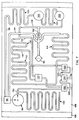
- Fig. 7 is a plan view showing the arrangement of a typical air pressure control device for use in controlling ink pressure in the printhead in accordance with the invention.
-
- In the typical embodiment of an ink jet printing system according to the invention shown in Fig. 1, a
main control unit 10 includes a remoteink supply reservoir 12 connected through anink supply conduit 14 in acable 15 to anink jet printhead 16 and apressure control unit 18 connected to theink jet printhead 16 through threeair conduits cable 15. In addition, themain control unit 10 includes atemperature control unit 22 for controlling the temperature of hot melt ink in various portions of the ink jet system in a manner to be described hereinafter. - To facilitate positioning of the
printhead 16 adjacent to different types of objects to which printing is to be applied, the printhead is movably supported on a vertically disposedcolumn 24 so as to be locked by aclamp 26 at any desired vertical position on the column. In addition, theprinthead 16 is supported for pivotal motion in any vertical plane by a clampableuniversal joint 28 so that the printhead can be oriented to permit a linear array ofink jet orifices 30 therein, best seen in Fig. 2, to project ink horizontally, either in a horizontal line or in a vertical line, or downwardly. - In the arrangement illustrated in Fig. 1, the printhead is disposed in a horizontal orientation as shown in solid lines to cause the printhead orifices 30 (shown in Fig. 2) to project a train of ink drops 31 downwardly onto the
top surfaces 32 of a series ofcontainers 34 which are conveyed in the horizontal direction by aconveyor 36, thus permitting appropriate information to be printed on the top surface of each of the containers. If desired, the printhead can be lowered on thecolumn 24 and theuniversal joint 28 can be arranged to clamp thehead 16 in a sidewise orientation with the array oforifices 30 extending vertically and facing thenear sides 37 of thecontainers 34, as viewed in the drawing, so as to cause information to be printed on the sides of each of the containers as they are conveyed past the printhead by theconveyor 36. - In still another printhead position, the printing system of the invention may be arranged to print a series of
labels 38 conveyed on atape 40 in a vertical direction from onereel 42 to anotherreel 44 by adjusting theuniversal joint 28 to clamp the printhead in a vertical orientation, as shown in dotted outline in Fig. 1, so that the array oforifices 30 extends horizontally and faces thelabels 38 as they are conveyed in the vertical direction. - The
ink supply reservoir 12 in themain control unit 10, which has asealing cover 46, is arranged to receive ablock 48 of solid hot melt ink and has a thermostatically controlledheater 50 connected by aline 52 to thetemperature control unit 22. Thetemperature control unit 22 is arranged to control theheater 50 so as to heat the block ofhot melt ink 48 sufficiently to melt it and to maintain the ink in thesupply reservoir 12 at a temperature just above its melting point so that it is sufficiently liquid that it can be transferred by apump 53 through thesupply conduit 14 to theprinthead 16 as required. At the same time, the ink temperature in thesupply reservoir 12 is kept low enough so that no appreciable degradation will take place even though the ink is maintained continuously at that temperature for several days or weeks. Similarly, theink supply conduit 14 contains a thermostatically controlledheater 54 connected through aline 56 to thetemperature control unit 22 so that the ink in the supply line is also maintained continuously in liquid condition, but at a temperature low enough that no appreciable degradation occurs. - As best seen in the enlarged schematic illustration of Fig. 2 and the further illustrations of Figs. 3-5, the
printhead 16 includes twoink reservoirs passage 62 leading from thehigh level reservoir 58 to adeaerator 64 and anotherpassage 66 leading from the low level reservoir to thedeaerator 64. Thepassages deaerator 64 adjacent to amembrane 68 which separates those passages from avacuum chamber 70 connected to thevacuum line 19 from thepressure control unit 18. That line and thechamber 70 are maintained at a pressure level of about 25 in.Hg. to extract dissolved air from the ink passing through thepassages membrane 68. After passing through thedeaerator 64, theink passages adjacent orifices 30 respectively in the array, ink from the low level reservoir being supplied through apassage 72 shown in Fig. 2 which extends downwardly adjacent to an orifice plate 74 to supply alternate odd-numbered orifices in the array, and ink from the high level reservoir being supplied downwardly to the bottom of the orifice plate 74 and upwardly adjacent to the orifice plate to the alternate even-numbered orifices 30 through apassage 73 illustrated in dotted line in Fig. 3. - Each of the
orifices 30 in theprinthead 16 has an associatedtransducer 76 arranged to respond to electrical signals to eject ink drops through the corresponding orifice in the usual manner, as described, for example, in US-A-4,584,590. An appropriate arrangement of theink passages transducers 76,orifices 30 andsupply passages - In order to maintain the ink in the
orifice passages orifices 30, aheater 78 is mounted in the printhead adjacent to thepassages line 79 in thecable 15 to thetemperature control unit 22. In addition, afurther heater 80 is mounted adjacent to thereservoirs control unit 22 by aline 81. The control unit is arranged to maintain the temperature of the ink in thereservoirs orifice passage heater 78 to heat the ink quickly to the jetting temperature as the ink is supplied through thepassages orifices 30. - As an example, for a hot melt ink which has a melting point of about 90°C and tends to degrade when maintained for substantial periods of time at temperatures above 130°C, the
temperature control unit 22 may be arranged to maintain the temperature of the ink in the remoteink supply reservoir 12 and in theink supply conduit 14 at a temperature of about 100°C and to control theheater 80 to maintain the ink in thereservoirs heater 78 so as to maintain the ink in thepassages orifices 30 at a jetting temperature of 137°C. Since only a small quantity of ink is maintained in thepassages - When the ink jet system is not in use, but is being maintained ready for use as, for example, during the course of a working day in which the system is used only periodically, the
temperature control unit 22 reduces the temperature of the ink in thepassages reservoirs reservoirs temperature control unit 22 can be arranged to maintain the ink in those reservoirs as well as in theorifice passageway 68 at an even lower temperature such as 120°C when the system is in the stand-by condition. - Since the solidification of molten hot melt ink normally causes the ink to contract in volume, air can be drawn into the
passages temperature control unit 22 is arranged to cause the ink in thereservoirs deaerator 64 to be maintained in the molten condition until the ink in thepassages passages orifices 30. - In order to maintain the pressure of the ink in the
orifices 30 at the desired negative pressure level during operation regardless of the elevation or orientation of theprinthead 16 with respect to the remoteink supply reservoir 12, theink supply conduit 14 leading from the remoteink supply reservoir 12 to the printhead includes acheck valve 82 which is spring-biased toward the closed position with sufficient force to require an ink pressure of, for example, at least 5 psi to open the valve and permit ink to pass from theline 14 into thelow level reservoir 60. Since thecheck valve 82 is closed except when ink is being supplied to thereservoir 60, the relative elevation of theprinthead 16 with respect to theink supply reservoir 12 will have no effect on the pressure of-the ink in thereservoirs passages orifices 30. - To maintain the pressure in the
orifices 30 at the desired negative level during normal operation, the printheadpressure control unit 18 in themain control unit 10 is connected through twoconduits reservoirs orifices 30 which is sufficient to prevent ink from seeping out of the orifices as a result of capillary action, but is not low enough to cause air to be drawn into thepassages orifices 30, which would interfere with the operation of the system. - As also described in US-A-4,835,554, each of the
ink passages ink passages reservoirs high level reservoir 58 to thelow level reservoir 60 through thedeaerator 64 in order to maintain the ink at theorifices 30 in a deaerated condition. As a result, the difference in the ink levels in the reservoirs is gradually reduced, thereby reducing the pressure which causes the ink to flow through the deaerator and the associated passages leading to theorifices 30. In order to restore the difference in the ink level in thereservoirs pressure control unit 18 periodically applies a higher negative pressure of about 3.2 inches (8,1 cm) of water through theline 84 to the ink in thereservoir 58, thereby drawing ink through acheck valve 87 from thelow level reservoir 60 to thehigh level reservoir 58 until the difference in the ink levels in the reservoirs balances the applied pressure difference. - In addition, when the ink jet system is started up after being cold, for example after having been turned off overnight, it may be necessary to purge air bubbles and debris from the
orifice passages lines orifice passages 68 and out of theorifices 30 to remove any air bubbles and debris which may be trapped in those passages. - Fig. 4 illustrates the
printhead 16 oriented in a position in which the array oforifices 30 extends in the vertical direction, such as to print information on the sides of thecontainers 34 as described above with reference to Fig. 1. In this case, because of the different elevations of thereservoirs low level reservoir 60 than at the orifices supplied by thehigh level reservoir 58, the ink pressure will normally be less at the orifices, which could cause air to be drawn into theink passages 72 receiving ink from the low level reservoir or produce seepage of ink at the orifices connected to thehigh level reservoir 58. In order to avoid this potential problem, thepressure control unit 18 is arranged to reduce the negative pressure applied to the high level reservoir while maintaining the desired negative pressure at the low level reservoir. For example, a negative pressure of about 1.1 inches of water may be applied through theline 86 to thelow level reservoir 60 while the usual negative pressure of about 2.8 inches of water is applied through theline 84 to thehigh level reservoir 58, providing a difference of about 1.7 inches of water between the negative pressures applied to the reservoirs to compensate for the difference in the height of the reservoirs as shown in Fig. 4 when the array is oriented in the vertical direction. - Fig. 5 illustrates the printhead when positioned to project ink downwardly from the
orifices 30, for example, to the top surfaces of the containers shown in Fig. 2. In this case, the two reservoirs are at the same elevation and the elevational difference between the reservoirs and the orifices is approximately the same as that of Figs. 2 and 3. Consequently, the same negative pressure of about 2.8 inches of water is applied to both reservoirs. - A representative arrangement of a
pressure control unit 18 to provide the various pressure levels described above is illustrated schematically in Fig. 6, in which thepressure control unit 18 and theprinthead 16 are shown in dotted outline. In thepressure control unit 18, apump 90 has an air intake connected through a two-position valve 92 alternatively to aline 94 leading to anintake filter 96 or to aline 98 connected through afirst restriction 100, anaccumulator 102, asecond restriction 104, and asecond accumulator 106 and then to aline 108 leading to thefilter 96 through a series of threesuccessive restrictions - The
pump 90 and the accumulators and restrictions are arranged so that a continuous flow of air is drawn through thefilter 96 and theline 108 to provide substantially constant negative pressures of about 3.2 inches of water at aline 116 connected between therestriction 110 and theline 108, about 2.8 inches (7,1 cm) of water at aline 118 between therestrictions line 120 connected between therestrictions position valve 122 is arranged to selectively connect aline 124 either to theline 116 or to theline 118 and theline 124 is selectively connected through another two-position valve 126 to aline 128 which is, in turn, connected to theconduit 84 leading to thehigh level reservoir 58 in theprinthead 16. - The positive pressure side of the
pump 90 is connected to aline 130 which opens to the atmosphere through arestriction 132 arranged to provide a constant positive air pressure of about 2 psi (0,16 kg/cm2) at thepump output line 130. When it is necessary to purge the system to remove debris or air bubbles from the orifice passageways, thevalve 126 is moved to a position connecting thepositive pressure line 130 through theline 128 and theconduit 84 to the high level reservoir to apply a purging pressure. At the same time, anothervalve 134 is moved to a position connecting theline 128 to aline 136 connected to theconduit 86 leading to thelow level reservoir 60 so that the 2 psi positive pressure is applied to both reservoirs at the same time. As a result, the ink in the orifice passageways 72 and 73 leading to theorifices 30 is ejected under pressure through the orifices, carrying with it any contaminants and air bubbles which may have accumulated. - After purging is completed, the
valves line 118 and theline 124 through theline 128 and theconduit 84 to the high level ink reservoir and through avalve 140, theline 136 and theconduit 86 to the low level ink reservoir. With the array of orifices oriented in the horizontal direction, this negative pressure level is maintained during normal operation. - When the ink level in the high level reservoir has been reduced as a result of the continuous flow of ink through the orifice passageways from the high level reservoir to the low level reservoir as described above, the
valve 122 is shifted to the other position, at which theline 116 is connected to theline 128 and theconduit 84 so as to apply a negative pressure of about 3.2 inches of water to thehigh level reservoir 58, thereby drawing ink from thelow level reservoir 60 through thecheck valve 87 into the high level reservoir. When the desired high ink level in that reservoir has been restored, thevalve 122 is returned to the position illustrated in Fig. 6. The rate of continuous flow of ink through the printhead from the high level reservoir to the low level reservoir is controlled by theorifice passageway restrictions 141 illustrated schematically in Fig. 6. - If the
printhead 16 is oriented with the array oforifices 30 extending in the vertical direction as shown in Fig. 4 with the right end as viewed in Fig. 6 higher than the left end of the array, thevalve 140 is shifted to a position at which theline 120 is connected to theline 136, thereby applying a reduced negative pressure of about 1.1 inches of water through theconduit 86 to thelower reservoir 60 to counteract any tendency for air to be drawn into theorifice passages 72. - In order to supply the necessary high vacuum to the
deaerator 64, thepressure control unit 18 includes avacuum pump 142 generating a vacuum of about 25 in.Hg. which is connected through aline 144 to theconduit 19 leading to thevacuum chamber 70 adjacent to themembrane 68 in thedeaerator 64 so as to extract dissolved air from the ink passing through the deaerator. Theline 144 includes avacuum sensor 146 to enable control of the vacuum produced by thepump 142 and applied to theline 144. Similarly, apressure sensor 150 is included in aline 152 connected between thelines pump 90 through thelines low level reservoir 60 in the printhead, alow ink sensor 153 detects a minimum level of ink in thelow level reservoir 60 and initiates the transfer of ink by thepump 53 from the remoteink supply reservoir 12 through theconduit 14 and thecheck valve 82 to the lowlevel printhead reservoir 60. - In order to inhibit leakage of ink from the
reservoirs vacuum lines printhead 16 is being moved or is tilted in such a way that the ink in the reservoirs is adjacent to the openings at which those lines are connected to the reservoirs, each of the reservoirs includes avacuum shield 154 at the openings connected to vacuum lines. These vacuum shields are made of Teflon or another material which is not wetted by the ink used in the system and they have a 0.016-inch opening at the end facing the ink in the reservoir leading to a 0.04-inch passage extending through the shield to the end connected to the vacuum line. Thus, when no vacuum is applied through thelines support clamp 28, the reservoirs may be oriented so that the ink is adjacent to the vacuum shields without causing the ink to flow through the vacuum shields to enter theconduits pressure control unit 18 is prevented from being contaminated with ink drawn into the vacuum line even though the printhead may have been oriented in such a way as to cause ink to flow against the openings leading to the vacuum lines while it is being mounted or transported. - A typical arrangement for providing various levels of negative and positive pressure in the
pressure control unit 18 is illustrated in Fig. 7. In this arrangement, analuminum plate 156 having a flat upper surface is formed with a series of grooves having uniform depth of about 0.040 inch and a width of approximately 1/16th inch each so as to provide a predetermined uniform resistance to air flow through the grooves. The exposed surface of the plate is covered, for example, by arigid thermoplastic sheet 158 which may be made of a rigid transparent material such as polystyrene or polymethacrylate laminated to theplate 156 so that the grooves are sealed by a flat surface at the surface of the plate. Thus, the total resistance to the flow of air through each groove is directly proportional to the length of the groove. In order to provide passages to and from the grooves of defined cross-section without substantial resistance to air flow, larger grooves of, for example, 1/8th inch width and depth, are provided. - In the example shown in Fig. 7, the grooves providing the flow restrictions illustrated schematically in the diagram of Fig. 6 are designated by corresponding reference numerals and the other elements of the pressure control system shown in Fig. 6, such as the
pump 90, thepressure sensor 150, thevalves - With this arrangement, desired pressure levels for a pressure control system can be provided accurately and conveniently by merely forming grooves of predetermined cross-section in the surface of a plate and making the relative lengths of the grooves proportional to the relative pressure differences required. Thus, for example, to provide the negative pressure values of 1.1 inches, 2.8 inches and 3.2 inches of water described above, the three
restrictions rigid cover 158 to theplate 156 prevents any air leakage between the cover and the plate while also as- - In order to test the
pressure control system 18 for leaks after it has been assembled, thevalves vacuum lines lines printhead 16 and the system is set to maintain a negative air pressure of, for example, 3.2 inches of water as detected by thesensor 150 between theintake filter 96 and theaccumulator 106. Depending upon the system parameters, the duty cycle for thepump 90 normally required to maintain the 3.2 inches negative air pressure may, for example, be about 33%. If the pump duty cycle is significantly different from such predetermined value when thelines valves - Similarly, the pump duty cycle required to maintain a 2 psi pressure in the
lines reservoirs valves printhead orifices 30 in a purging operation. Again, if the duty cycles required to maintain the desired 2 psi pressure in the cold condition and in the heated condition depart significantly from the predetermined values, leakage or blockage of the pressure supply system is indicated. In this way, the pressure control system can be tested conveniently in conjunction with the printhead after assembly.
Claims (21)
- Ink jet printing apparatus comprising printhead means (16) for selectively ejecting ink drops through a plurality of orifices (30) toward a surface to form a desired pattern on the surface, remote ink supply means (12) for retaining a supply of ink to be used in the printhead means, conduit means (14) connecting the remote ink supply means with the printhead means to supply ink thereto, support means (24, 26) for supporting the printhead at a variable vertical level with respect to the remote supply means, valve means (82) for normally isolating the ink in the printhead means from the remote ink supply means, and pressure control means (18) connected to the printhead means, characterised in that the pressure control means (18) is connected through an air duct (84, 86) to the printhead means for applying a selected air pressure thereto maintaining a pressure of the ink at the orifices therein at a desired level.
- The apparatus of Claim 1, including pump means (53) for pumping ink from the remote ink supply means (12) through the conduit means (14) to the printhead means (16) and wherein the valve means (82) is responsive to ink pressure exceeding a selected level to permit ink to be transmitted through the conduit means (14) to the printhead means (16).
- The apparatus of Claim 1 or 2, wherein the printhead means (16) includes ink deaeration means (68, 70) and wherein the pressure control means (18) includes means (19, 144, 142) for supplying negative air pressure to the printhead means (16) for deaeration of the ink therein.
- The apparatus of Claims 1, 2 or 3, including restricted orifices means (154) in the printhead means for connecting the pressure control means (18) to the printhead means (16) and for inhibiting passage of ink from the printhead means to the pressure control means.
- Apparatus according to any preceding claim, wherein the pressure control means (18) comprises means (110,112, 114) for generating a plurality of air pressure levels and means (140) for selectively applying at least one of the air pressure levels to the ink in the printhead means.
- The apparatus of Claim 5, wherein the means (110, 112, 114) for generating a plurality of air pressure levels comprises a plurality of air flow paths of different length, each providing a different total resistance to air flow to produce different negative pressure levels.
- The apparatus of Claim 6 wherein the air flow paths (110, 112, 114) are connected in series to produce successively increasing negative pressure levels.
- The apparatus of Claims 6 or 7, wherein the ink pressure control means (110, 112, 114) comprises a plurality of grooves of defined depth and width formed in the surface of a plate (156).
- The apparatus of Claim 8, wherein the resistance to air flow of the grooves is proportional to the length of the grooves.
- The apparatus of Claims 8 or 9, including thermoplastic plate means (158) sealed to the surface of the grooved plate (156) to enclose the grooves (110, 112, 114) formed therein and assure uniform cross-sectional area of the grooves throughout their length.
- The apparatus of Claims 8, 9 or 10, further comprising pump means (80) for pumping air through the plurality of air flow paths (110, 112, 114) providing predetermined resistance to flow of air so as to produce said selected negative pressure levels wherein the pump means (90) is mounted on the plate means (158) and including valve means (122,126, 134, 140) mounted on the plate means for controlling the flow of air through the grooves.
- The apparatus of any preceding claims wherein the orifices (30) in the printhead means are disposed in a directional array and the support means includes positioning means (28) arranged to permit a change in the orientation of the directional array of orifices with respect to a horizontal plane.
- The apparatus of Claim 12, wherein the positioning means (28) is arranged to position the printhead means (16) to permit the orifices (30) to project ink drops in a horizontal direction or in a vertical direction.
- The apparatus of Claims 12 or 13, wherein the pressure control means (18) includes means for controlling the ink pressure at different levels at opposite ends of the directional array of orifices.
- The apparatus of any preceding claims, for use with hot melt ink, and further comprising reservoir means (58, 60) in the printhead means for holding a supply of ink to be ejected by the printhead means, ink passage means (72, 73) connecting the reservoir means (56, 60) to the orifices (30) in the printhead means to supply ink thereto, first heater means (78) for heating the ink in the ink passage means (72, 73), second heater means (80) for heating the ink in the reservoir means (58, 60), third heater means (54) for heating the ink in the supply conduit means (14), and fourth heater means (50) for heating the ink in the remote ink supply means (12), and temperature control means for maintaining the temperature of the ink in the ink passage means (72, 73) at a temperature sufficient to permit ejection of the ink through the orifices (30), for maintaining the temperature of the ink in the reservoir means (58, 60) at a temperature below the temperature of ink in the orifice passage and for maintaining the temperature of the ink in the supply conduit means (14) and the remote ink supply means (12) at temperature above the melting point of the ink but below the temperature of the ink in the reservoir means to prevent high-temperature degradation thereof while permitting transfer of ink from the remote ink supply means through the supply conduit means to the reservoir means.
- The apparatus of any preceding claim wherein the printhead means includes two ink reservoirs (58, 60) with different ink levels and passage means for conducting ink from a high level reservoir (58) past the orifice means (30) to a low level reservoir (60), and check valve means permitting ink under pressure to be transferred from the low level reservoir to the high level reservoir and wherein the pressure control means (18) includes means for applying air pressure to the low level reservoir which is higher than the pressure applied by the pressure control means to the high level reservoir to cause ink to be transferred from the low level reservoir through the check valve means to the high level reservoir.
- The apparatus of any preceding claim, including conveyor means for conveying a series of objects on which a pattern is to be printed past the printhead.
- The apparatus of Claim 17, wherein the conveyor means comprises a horizontal conveyor.
- The apparatus of Claim 18 wherein the support means is arranged to position the printhead means with the array of orifices in a horizontal plane to permit printing on upper horizontal surfaces of the objects.
- The apparatus of Claims 16, 17 or 18 wherein the support means is arranged to position the printhead with the orifices disposed in a vertical plane to permit printing on vertically-oriented surfaces of the objects.
- The apparatus of Claim 17, wherein the conveyor means comprises a support member for conveying labels to be printed past the orifices in the printhead means.
Priority Applications (1)
| Application Number | Priority Date | Filing Date | Title |
|---|---|---|---|
| EP99201319A EP0933217B1 (en) | 1993-05-04 | 1994-04-11 | Ink jet printing system |
Applications Claiming Priority (2)
| Application Number | Priority Date | Filing Date | Title |
|---|---|---|---|
| US08/057,091 US5489925A (en) | 1993-05-04 | 1993-05-04 | Ink jet printing system |
| US57091 | 1993-05-04 |
Related Child Applications (1)
| Application Number | Title | Priority Date | Filing Date |
|---|---|---|---|
| EP99201319A Division EP0933217B1 (en) | 1993-05-04 | 1994-04-11 | Ink jet printing system |
Publications (3)
| Publication Number | Publication Date |
|---|---|
| EP0623472A2 EP0623472A2 (en) | 1994-11-09 |
| EP0623472A3 EP0623472A3 (en) | 1997-03-26 |
| EP0623472B1 true EP0623472B1 (en) | 2000-09-20 |
Family
ID=22008443
Family Applications (2)
| Application Number | Title | Priority Date | Filing Date |
|---|---|---|---|
| EP94302528A Expired - Lifetime EP0623472B1 (en) | 1993-05-04 | 1994-04-11 | Ink jet printing system |
| EP99201319A Expired - Lifetime EP0933217B1 (en) | 1993-05-04 | 1994-04-11 | Ink jet printing system |
Family Applications After (1)
| Application Number | Title | Priority Date | Filing Date |
|---|---|---|---|
| EP99201319A Expired - Lifetime EP0933217B1 (en) | 1993-05-04 | 1994-04-11 | Ink jet printing system |
Country Status (6)
| Country | Link |
|---|---|
| US (2) | US5489925A (en) |
| EP (2) | EP0623472B1 (en) |
| JP (1) | JP2745285B2 (en) |
| DE (2) | DE69432374T2 (en) |
| ES (2) | ES2151532T3 (en) |
| GB (1) | GB2278088B (en) |
Families Citing this family (122)
| Publication number | Priority date | Publication date | Assignee | Title |
|---|---|---|---|---|
| US5920332A (en) | 1993-05-04 | 1999-07-06 | Markem Corporation | Ink barrier for fluid reservoir vacuum or pressure line |
| US5622897A (en) * | 1993-05-20 | 1997-04-22 | Compaq Computer Corporation | Process of manufacturing a drop-on-demand ink jet printhead having thermoelectric temperature control means |
| US5659346A (en) * | 1994-03-21 | 1997-08-19 | Spectra, Inc. | Simplified ink jet head |
| US5771052A (en) * | 1994-03-21 | 1998-06-23 | Spectra, Inc. | Single pass ink jet printer with offset ink jet modules |
| DE69515888T2 (en) * | 1994-09-16 | 2000-07-20 | Videojet Systems International, Inc. | CONTINUOUSLY WORKING INK JET PRINTER FOR USE WITH HOT MELT INKS |
| JP3157992B2 (en) * | 1994-09-30 | 2001-04-23 | シャープ株式会社 | Ink jet recording device |
| US5736992A (en) * | 1994-10-31 | 1998-04-07 | Hewlett-Packard | Pressure regulated free-ink ink-jet pen |
| US5751319A (en) * | 1995-08-31 | 1998-05-12 | Colossal Graphics Incorporated | Bulk ink delivery system and method |
| US6305769B1 (en) | 1995-09-27 | 2001-10-23 | 3D Systems, Inc. | Selective deposition modeling system and method |
| JPH10146959A (en) * | 1996-11-15 | 1998-06-02 | Brother Ind Ltd | Hot melt inkjet printer head |
| JPH10146961A (en) * | 1996-11-15 | 1998-06-02 | Brother Ind Ltd | Hot melt inkjet printer head |
| US6109803A (en) * | 1997-02-13 | 2000-08-29 | Brother Kogyo Kabushiki Kaisha | Information recording method and printer |
| JPH10230623A (en) * | 1997-02-21 | 1998-09-02 | Hitachi Koki Co Ltd | Apparatus and method for removing bubbles from ink jet printer using heat-melt ink |
| JP3363052B2 (en) * | 1997-03-12 | 2003-01-07 | コピア株式会社 | Ink supply device and ink filling method |
| US6022104A (en) * | 1997-05-02 | 2000-02-08 | Xerox Corporation | Method and apparatus for reducing intercolor bleeding in ink jet printing |
| US6513902B1 (en) | 1998-02-03 | 2003-02-04 | Fuji Photo Film Co., Ltd. | Apparatus for restoring ink jet recording head |
| US6293638B1 (en) * | 1998-02-04 | 2001-09-25 | Spectra, Inc. | Bar code printing on cartons with hot melt ink |
| US5967045A (en) * | 1998-10-20 | 1999-10-19 | Imation Corp. | Ink delivery pressure control |
| GB9828476D0 (en) | 1998-12-24 | 1999-02-17 | Xaar Technology Ltd | Apparatus for depositing droplets of fluid |
| GB9910313D0 (en) * | 1999-05-05 | 1999-06-30 | Cambridge Consultants | Fluid-pressure controlled ink pressure regulator |
| US6357867B1 (en) | 1999-05-07 | 2002-03-19 | Spectra, Inc. | Single-pass inkjet printing |
| US6523944B1 (en) * | 1999-06-30 | 2003-02-25 | Xerox Corporation | Ink delivery system for acoustic ink printing applications |
| US6119531A (en) * | 1999-08-03 | 2000-09-19 | Case Corporation | Crop sampling system |
| JP3700049B2 (en) * | 1999-09-28 | 2005-09-28 | 日本碍子株式会社 | Droplet discharge device |
| AU1083101A (en) * | 1999-10-12 | 2001-04-23 | Allan R. Will | Methods and devices for protecting a passageway in a body |
| EP1754608B1 (en) * | 2000-01-21 | 2008-07-23 | Seiko Epson Corporation | Ink-jet recording apparatus |
| NL1014294C2 (en) * | 2000-02-04 | 2001-08-07 | Ocu Technologies B V | Melting device and an inkjet printer provided with such a melting device. |
| US6281916B1 (en) | 2000-03-21 | 2001-08-28 | Fas-Co Coders Inc. | Ink supply apparatus and method |
| US7212300B2 (en) * | 2000-04-06 | 2007-05-01 | Illinois Tool Works, Inc. | Printing systems accessible from remote locations |
| JP3416614B2 (en) * | 2000-04-26 | 2003-06-16 | キヤノン株式会社 | Ink jet recording device |
| AUPQ756300A0 (en) * | 2000-05-16 | 2000-06-08 | Champion Imaging Systems Pty Ltd | Ink supply system |
| CA2350397C (en) * | 2000-06-16 | 2006-01-10 | Canon Kabushiki Kaisha | Solid semiconductor element, ink tank, ink jet recording apparatus provided with ink tank, liquid information acquiring method and liquid physical property change discriminating method |
| GB2370016B (en) * | 2000-10-31 | 2003-01-15 | Zipher Ltd | Printing apparatus |
| DE10056602C1 (en) * | 2000-11-15 | 2002-04-04 | Roehm Gmbh | Writing device, for extrusion plant, monitors pressure in line between writing fluid container and writing head for detecting leak |
| DE60223376T2 (en) * | 2001-07-13 | 2008-08-28 | Datacard Corp., Minnetonka | DEVICE FOR DIGITAL INK JET PRINTING AND INK TANK |
| FR2827212B1 (en) * | 2001-07-13 | 2008-03-21 | Leroux Gilles Sa | INK JET DIGITAL PRINTING DEVICE AND INK CIRCUIT |
| FR2827216B1 (en) * | 2001-07-13 | 2008-03-21 | Leroux Gilles Sa | INK JET DIGITAL PRINTING DEVICE AND INK TANK |
| JP4218245B2 (en) * | 2002-01-31 | 2009-02-04 | セイコーエプソン株式会社 | Inkjet printer |
| JP2003305831A (en) * | 2002-04-15 | 2003-10-28 | Sharp Corp | Inkjet printer |
| US6877846B2 (en) * | 2002-05-03 | 2005-04-12 | Eastman Kodak Company | Replaceable ink jet supply with anti-siphon back pressure control |
| US6722752B2 (en) * | 2002-09-04 | 2004-04-20 | Hewlett-Packard Development Company, L.P. | Pen maintenance system and method for operating same |
| WO2004037543A2 (en) * | 2002-10-24 | 2004-05-06 | Nur Macroprinters Ltd. | Advancing system and method for a digital printing apparatus |
| JP4022133B2 (en) * | 2002-11-26 | 2007-12-12 | 東芝テック株式会社 | Inkjet recording device |
| US6824241B2 (en) * | 2002-12-16 | 2004-11-30 | Xerox Corporation | Ink jet apparatus |
| US6866375B2 (en) * | 2002-12-16 | 2005-03-15 | Xerox Corporation | Solid phase change ink melter assembly and phase change ink image producing machine having same |
| US7104637B1 (en) | 2003-02-18 | 2006-09-12 | Imaje Ab | Ink supply system and method of supplying ink |
| JP4421198B2 (en) * | 2003-03-04 | 2010-02-24 | 東芝テック株式会社 | Ink evaluation method, ink, and ink ejection device |
| JP4461728B2 (en) * | 2003-07-29 | 2010-05-12 | ブラザー工業株式会社 | Inkjet recording apparatus and ink supply apparatus |
| JP4635426B2 (en) * | 2003-10-22 | 2011-02-23 | ブラザー工業株式会社 | Image forming apparatus |
| CN100395112C (en) * | 2003-12-24 | 2008-06-18 | 杭州宏华数码科技股份有限公司 | Real-time automatic cleaning method and device for nozzle of digital inkjet printer |
| US7063410B2 (en) * | 2004-02-25 | 2006-06-20 | Xerox Corporation | Ink jet apparatus |
| US7207668B2 (en) * | 2004-03-22 | 2007-04-24 | Xerox Corporation | Ink supply container for high speed solid ink printers |
| US7281785B2 (en) * | 2004-09-17 | 2007-10-16 | Fujifilm Dimatix, Inc. | Fluid handling in droplet deposition systems |
| GB0428480D0 (en) * | 2004-12-30 | 2005-02-02 | Domino Printing Sciences Plc | Improvements in or relating to continuous inkjet printers |
| US20060152558A1 (en) * | 2005-01-07 | 2006-07-13 | Hoisington Paul A | Fluid drop ejection |
| US7413299B2 (en) * | 2005-03-15 | 2008-08-19 | Xerox Corporation | Pressurizing a heatable printhead while it cools |
| US7401908B2 (en) * | 2005-03-31 | 2008-07-22 | Heidelberger Druckmaschinen Ag | Ink jet device with ink deaerator |
| KR100662559B1 (en) * | 2005-05-09 | 2006-12-28 | 삼성전자주식회사 | Inkjet Printers and Inkjet Printhead Devices |
| US7458669B2 (en) * | 2005-06-09 | 2008-12-02 | Xerox Corporation | Ink consumption determination |
| US7425061B2 (en) * | 2005-06-09 | 2008-09-16 | Xerox Corporation | Ink consumption determination |
| US7407276B2 (en) * | 2005-06-09 | 2008-08-05 | Xerox Corporation | Ink level sensing |
| US7591550B2 (en) * | 2005-06-09 | 2009-09-22 | Xerox Corporation | Ink consumption determination |
| JP5030423B2 (en) * | 2005-06-23 | 2012-09-19 | エスアイアイ・プリンテック株式会社 | Inkjet head and inkjet recording apparatus |
| US7416292B2 (en) * | 2005-06-30 | 2008-08-26 | Xerox Corporation | Valve system for molten solid ink and method for regulating flow of molten solid ink |
| US7325910B2 (en) * | 2005-08-30 | 2008-02-05 | Pelletier Andree | Sublimation pen for use in a dye sublimation printing system, and method of use of the dye sublimation printing system |
| WO2007041754A1 (en) * | 2005-10-11 | 2007-04-19 | Silverbrook Research Pty Ltd | Method of removing particulates from a printhead using a rotating roller |
| US7467858B2 (en) * | 2005-10-12 | 2008-12-23 | Hewlett-Packard Development Company, L.P. | Back pressure control in inkjet printing |
| EP1803570B1 (en) * | 2005-11-14 | 2010-06-02 | Océ-Technologies B.V. | Ink jet device with purging device |
| JP5107554B2 (en) * | 2005-11-14 | 2012-12-26 | オセ−テクノロジーズ ビーブイ | Inkjet device with purge device |
| US7581827B2 (en) * | 2006-04-26 | 2009-09-01 | Xerox Corporation | System and method for melting solid ink sticks in a phase change ink printer |
| EP1872952A1 (en) * | 2006-06-28 | 2008-01-02 | Océ-Technologies B.V. | Ink jet printhead with an acoustic filter |
| JP4386056B2 (en) * | 2006-08-08 | 2009-12-16 | セイコーエプソン株式会社 | Method for manufacturing liquid container |
| US8186817B2 (en) * | 2006-08-29 | 2012-05-29 | Xerox Corporation | System and method for transporting fluid through a conduit |
| US7753512B2 (en) | 2006-12-20 | 2010-07-13 | Xerox Corporation | System for maintaining temperature of a fluid in a conduit |
| US7568795B2 (en) * | 2006-12-22 | 2009-08-04 | Xerox Corporation | Heated ink delivery system |
| US20080221543A1 (en) * | 2007-03-06 | 2008-09-11 | Todd Wilkes | Disposable absorbent product having a graphic indicator |
| JP4971942B2 (en) * | 2007-10-19 | 2012-07-11 | 富士フイルム株式会社 | Inkjet recording apparatus and recording method |
| US8297745B2 (en) * | 2007-11-30 | 2012-10-30 | Samsung Electronics Co., Ltd. | Image forming apparatus |
| US8342661B2 (en) * | 2007-12-19 | 2013-01-01 | Canon Finetech Inc. | Ink supplying apparatus, inkjet printing apparatus, inkjet printing head, ink supplying method and inkjet printing method |
| WO2009102315A1 (en) | 2008-02-11 | 2009-08-20 | Hewlett-Packard Development Company, L.P. | Self-cleaning ink supply systems |
| US8052264B2 (en) * | 2008-03-26 | 2011-11-08 | Xerox Corporation | Melting device for increased production of melted ink in a solid ink printer |
| JP5009229B2 (en) * | 2008-05-22 | 2012-08-22 | 富士フイルム株式会社 | Inkjet recording device |
| US8006967B2 (en) * | 2008-08-19 | 2011-08-30 | Silverbrook Research Pty Ltd | Cradle assembly for a pressure decay leak tester |
| US7984640B2 (en) * | 2008-08-19 | 2011-07-26 | Silverbrook Research Pty Ltd. | Pressure-based tester for a platform assembly |
| US7987699B2 (en) * | 2008-08-19 | 2011-08-02 | Silverbrook Research Pty Ltd | Pneumatic assembly for a pressure decay tester |
| KR101132364B1 (en) * | 2008-09-08 | 2012-04-03 | 삼성전기주식회사 | Ink-jet Printer |
| US7959277B2 (en) * | 2008-11-18 | 2011-06-14 | Xerox Corporation | Air filter for use with a liquid ink umbilical interface in a printer |
| US20100208017A1 (en) * | 2009-02-19 | 2010-08-19 | Black Dot Technology, Inc. | Imaging module for hot melt wax ink jet printer |
| JP2010214721A (en) * | 2009-03-16 | 2010-09-30 | Seiko Epson Corp | Liquid holding container |
| US8360566B2 (en) * | 2009-04-09 | 2013-01-29 | Plastipak Packaging, Inc. | Method for printing |
| US8308278B2 (en) | 2010-04-02 | 2012-11-13 | Xerox Corporation | System and method for operating a conduit to transport fluid through the conduit |
| US8303098B2 (en) * | 2010-05-07 | 2012-11-06 | Xerox Corporation | High flow ink delivery system |
| US8292392B2 (en) | 2010-07-15 | 2012-10-23 | Xerox Corporation | System and method for modifying operation of an inkjet printer to accommodate changing environmental conditions |
| US8454147B2 (en) * | 2010-07-31 | 2013-06-04 | Xerox Corporation | Method and system for delivering solid-ink pellets |
| US20120044292A1 (en) * | 2010-08-17 | 2012-02-23 | Markem-Imaje Corporation | Vacuum Control For Print Head of A Printing System |
| US8348405B2 (en) * | 2010-09-02 | 2013-01-08 | Xerox Corporation | System and method for transporting solid ink pellets |
| US8556372B2 (en) | 2011-02-07 | 2013-10-15 | Palo Alto Research Center Incorporated | Cooling rate and thermal gradient control to reduce bubbles and voids in phase change ink |
| US8562117B2 (en) | 2011-02-07 | 2013-10-22 | Palo Alto Research Center Incorporated | Pressure pulses to reduce bubbles and voids in phase change ink |
| US8506063B2 (en) | 2011-02-07 | 2013-08-13 | Palo Alto Research Center Incorporated | Coordination of pressure and temperature during ink phase change |
| US20120200630A1 (en) * | 2011-02-07 | 2012-08-09 | Palo Alto Research Center Incorporated | Reduction of bubbles and voids in phase change ink |
| US8974045B2 (en) * | 2011-04-13 | 2015-03-10 | Fujifilm Dimatix, Inc. | Phase-change ink jetting |
| GB2492593A (en) * | 2011-07-08 | 2013-01-09 | Inca Digital Printers Ltd | Pressure regulation system |
| US20130021415A1 (en) * | 2011-07-18 | 2013-01-24 | Casey Walker | Ink Delivery Agitation System |
| US8529038B2 (en) * | 2011-08-18 | 2013-09-10 | Xerox Corporation | System and method for pressure control of an ink delivery system |
| TW201420366A (en) * | 2012-07-10 | 2014-06-01 | Zamtec Ltd | Printer configured for efficient air bubble removal |
| US9180674B2 (en) | 2013-02-08 | 2015-11-10 | R.R. Donnelley & Sons Company | System and method for supplying ink to an inkjet cartridge |
| US9709969B2 (en) | 2013-03-15 | 2017-07-18 | Deere & Company | Methods and apparatus to control machine configurations |
| JP2015134486A (en) | 2014-01-20 | 2015-07-27 | セイコーエプソン株式会社 | Liquid storage container |
| US12251946B2 (en) | 2014-06-17 | 2025-03-18 | Kateeva, Inc. | Printing system assemblies and methods |
| EP3157687A4 (en) | 2014-06-17 | 2018-03-14 | Kateeva, Inc. | Printing system assemblies and methods |
| CN207291314U (en) | 2016-05-09 | 2018-05-01 | R.R.当纳利父子公司 | Ink feeding unit |
| US9961783B2 (en) | 2016-07-08 | 2018-05-01 | Kateeva, Inc. | Guided transport path correction |
| DE102016217881A1 (en) | 2016-09-19 | 2018-03-22 | Kba-Metronic Gmbh | pressure unit |
| DE102016217879A1 (en) | 2016-09-19 | 2018-03-22 | Kba-Metronic Gmbh | pressure unit |
| DE102016217878A1 (en) | 2016-09-19 | 2018-03-22 | Kba-Metronic Gmbh | pressure unit |
| CN109789704A (en) * | 2016-09-19 | 2019-05-21 | 科尼希鲍尔标识科技有限公司 | printing assembly |
| DE102016217877A1 (en) | 2016-09-19 | 2018-03-22 | Kba-Metronic Gmbh | pressure unit |
| US20210316553A1 (en) * | 2018-11-21 | 2021-10-14 | Hewlett-Packard Development Company, L.P. | Curved fluid ejection modules |
| CN111318706A (en) * | 2018-12-17 | 2020-06-23 | 北京梦之墨科技有限公司 | Ink discharge control system, ink discharge dynamic control system, and ink storage container |
| WO2021211128A1 (en) * | 2020-04-16 | 2021-10-21 | Hewlett-Packard Development Company, L.P. | Purge valve assemblies |
| US11548290B2 (en) | 2020-08-28 | 2023-01-10 | Markem-Imaje Corporation | Systems and techniques for melting hot melt ink in industrial printing systems |
| DE102023112590A1 (en) * | 2023-05-12 | 2024-11-14 | Homag Gmbh | Device and method for patterning a workpiece |
Family Cites Families (40)
| Publication number | Priority date | Publication date | Assignee | Title |
|---|---|---|---|---|
| US4125845A (en) * | 1977-08-25 | 1978-11-14 | Silonics, Inc. | Ink jet print head pressure and temperature control circuits |
| EP0036295A3 (en) * | 1980-03-14 | 1981-10-07 | Printos B.V. | Hand-held printing apparatus |
| US4340896A (en) * | 1980-12-22 | 1982-07-20 | Pitney Bowes Inc. | Impulse ink jet ink delivery apparatus |
| JPS57187267A (en) * | 1981-05-04 | 1982-11-17 | Xerox Corp | Ink jet printing method and its device |
| EP0076708B1 (en) * | 1981-10-07 | 1987-02-04 | Nec Corporation | Multi-nozzle ink-jet print head of drop-on-demand type |
| US5182572A (en) * | 1981-12-17 | 1993-01-26 | Dataproducts Corporation | Demand ink jet utilizing a phase change ink and method of operating |
| US4404566A (en) * | 1982-03-08 | 1983-09-13 | The Mead Corporation | Fluid system for fluid jet printing device |
| EP0095911B1 (en) | 1982-05-28 | 1989-01-18 | Xerox Corporation | Pressure pulse droplet ejector and array |
| US4494124A (en) * | 1983-09-01 | 1985-01-15 | Eastman Kodak Company | Ink jet printer |
| US4602662A (en) * | 1983-10-11 | 1986-07-29 | Videojet Systems International, Inc. | Valve for liquid marking systems |
| US4607266A (en) * | 1984-10-15 | 1986-08-19 | Debonte William J | Phase change ink jet with independent heating of jet and reservoir |
| US4571599A (en) * | 1984-12-03 | 1986-02-18 | Xerox Corporation | Ink cartridge for an ink jet printer |
| JPH0534935Y2 (en) * | 1984-12-28 | 1993-09-03 | ||
| IT1182645B (en) * | 1985-10-31 | 1987-10-05 | Olivetti & Co Spa | INK JET PRINT HEAD WITH DEVICE FOR DETECTION OF MALFUNCTIONS OF A PRINTING ELEMENT |
| US4683481A (en) * | 1985-12-06 | 1987-07-28 | Hewlett-Packard Company | Thermal ink jet common-slotted ink feed printhead |
| US4651161A (en) * | 1986-01-17 | 1987-03-17 | Metromedia, Inc. | Dynamically varying the pressure of fluid to an ink jet printer head |
| US4700205A (en) * | 1986-01-17 | 1987-10-13 | Metromedia Company | Hydraulic servomechanism for controlling the pressure of writing fluid in an ink jet printing system |
| JPS62292438A (en) * | 1986-06-13 | 1987-12-19 | Canon Inc | Inkjet recording device |
| US4727378A (en) * | 1986-07-11 | 1988-02-23 | Tektronix, Inc. | Method and apparatus for purging an ink jet head |
| US4734711A (en) * | 1986-12-22 | 1988-03-29 | Eastman Kodak Company | Pressure regulation system for multi-head ink jet printing apparatus |
| EP0282049B1 (en) * | 1987-03-13 | 1992-11-11 | Jan Slomianny | Ink system for an ink jet matrix printer |
| GB8708884D0 (en) * | 1987-04-14 | 1987-05-20 | Domino Printing Sciences Plc | Control of ink jet printing system |
| US4814786A (en) * | 1987-04-28 | 1989-03-21 | Spectra, Inc. | Hot melt ink supply system |
| JPH02500462A (en) * | 1987-08-06 | 1990-02-15 | ミラー ジョン エス | Current detection device with wide response frequency range |
| US4835554A (en) | 1987-09-09 | 1989-05-30 | Spectra, Inc. | Ink jet array |
| US4791438A (en) * | 1987-10-28 | 1988-12-13 | Hewlett-Packard Company | Balanced capillary ink jet pen for ink jet printing systems |
| US4870431A (en) * | 1987-11-02 | 1989-09-26 | Howtek, Inc. | Ink jet priming system |
| US4929963A (en) * | 1988-09-02 | 1990-05-29 | Hewlett-Packard Company | Ink delivery system for inkjet printer |
| US5103243A (en) * | 1988-12-16 | 1992-04-07 | Hewlett-Packard Company | Volumetrically efficient ink jet pen capable of extreme altitude and temperature excursions |
| US4992802A (en) * | 1988-12-22 | 1991-02-12 | Hewlett-Packard Company | Method and apparatus for extending the environmental operating range of an ink jet print cartridge |
| US5189443A (en) * | 1989-09-18 | 1993-02-23 | Canon Kabushiki Kaisha | Recording head having stress-minimizing construction |
| SE465158B (en) * | 1989-12-12 | 1991-08-05 | Markpoint System Ab | DEVICE FOR SCREW RADIATORS |
| US5121130A (en) * | 1990-11-05 | 1992-06-09 | Xerox Corporation | Thermal ink jet printing apparatus |
| US5113199A (en) * | 1991-03-11 | 1992-05-12 | Hewlett-Packard Company | Ink delivery system for ink jet printers |
| EP0506403B1 (en) * | 1991-03-25 | 1995-08-23 | Tektronix, Inc. | Method and apparatus for providing phase change ink to an ink jet printer |
| US5185614A (en) * | 1991-04-17 | 1993-02-09 | Hewlett-Packard Company | Priming apparatus and process for multi-color ink-jet pens |
| US5184147A (en) * | 1991-04-22 | 1993-02-02 | Tektronix, Inc. | Ink jet print head maintenance system |
| JPH0569541A (en) * | 1991-09-17 | 1993-03-23 | Brother Ind Ltd | Ink discharge device of ink-jet printer |
| US5418557A (en) * | 1991-10-03 | 1995-05-23 | Videojet Systems International, Inc. | Drop quality control system for jet printing |
| US5406315A (en) * | 1992-07-31 | 1995-04-11 | Hewlett-Packard Company | Method and system for remote-sensing ink temperature and melt-on-demand control for a hot melt ink jet printer |
-
1993
- 1993-05-04 US US08/057,091 patent/US5489925A/en not_active Expired - Lifetime
-
1994
- 1994-04-11 ES ES94302528T patent/ES2151532T3/en not_active Expired - Lifetime
- 1994-04-11 DE DE69432374T patent/DE69432374T2/en not_active Expired - Fee Related
- 1994-04-11 GB GB9407159A patent/GB2278088B/en not_active Expired - Lifetime
- 1994-04-11 ES ES99201319T patent/ES2190173T3/en not_active Expired - Lifetime
- 1994-04-11 DE DE69425922T patent/DE69425922T2/en not_active Expired - Lifetime
- 1994-04-11 EP EP94302528A patent/EP0623472B1/en not_active Expired - Lifetime
- 1994-04-11 EP EP99201319A patent/EP0933217B1/en not_active Expired - Lifetime
- 1994-04-28 JP JP6091068A patent/JP2745285B2/en not_active Expired - Fee Related
-
1995
- 1995-11-13 US US08/556,255 patent/US5910810A/en not_active Expired - Lifetime
Also Published As
| Publication number | Publication date |
|---|---|
| EP0623472A2 (en) | 1994-11-09 |
| ES2151532T3 (en) | 2001-01-01 |
| DE69425922T2 (en) | 2001-01-18 |
| DE69432374D1 (en) | 2003-04-30 |
| EP0933217B1 (en) | 2003-03-26 |
| EP0933217A3 (en) | 1999-08-11 |
| GB2278088B (en) | 1997-02-19 |
| DE69425922D1 (en) | 2000-10-26 |
| US5910810A (en) | 1999-06-08 |
| ES2190173T3 (en) | 2003-07-16 |
| JP2745285B2 (en) | 1998-04-28 |
| GB2278088A (en) | 1994-11-23 |
| US5489925A (en) | 1996-02-06 |
| EP0933217A2 (en) | 1999-08-04 |
| JPH07125254A (en) | 1995-05-16 |
| DE69432374T2 (en) | 2003-10-23 |
| GB9407159D0 (en) | 1994-06-01 |
| EP0623472A3 (en) | 1997-03-26 |
Similar Documents
| Publication | Publication Date | Title |
|---|---|---|
| US5489925A (en) | Ink jet printing system | |
| EP1393907B1 (en) | Droplet deposition apparatus | |
| CN101412322B (en) | Inkjet recording apparatus and recording method | |
| CA1299914C (en) | Hot melt ink supply system | |
| EP3381698B1 (en) | Dual regulator print module | |
| US20080055378A1 (en) | Fluid Supply Method and Apparatus | |
| EP0666177B1 (en) | Ink circulation in ink jet pens | |
| EP0770490B1 (en) | Method and apparatus for removing air from an ink-jet print cartridge | |
| US5220345A (en) | Ink jet recording apparatus | |
| US20100073439A1 (en) | Shuttle mounted pressure control device for inkjet printer | |
| EP0953447B1 (en) | Ink flow design to provide increased heat removal from an inkjet printhead and to provide for air accumulation | |
| JP2017209864A (en) | Liquid discharge device and liquid discharge head | |
| WO2012024125A1 (en) | Vacuum control for print head of a printing system | |
| EP0875385B1 (en) | An ink delivery that utilizes a separate insertable filter carrier | |
| CN101072684A (en) | Fluid supply method and apparatus | |
| EP0390198B1 (en) | An ink jet recording apparatus | |
| KR102279172B1 (en) | Liquid discharge apparatus and liquid discharge head | |
| GB2297725A (en) | A hot melt ink jet printing system | |
| EP1642729B1 (en) | Sheet handling device with sheet support plate and temperature control system | |
| JP2023170109A (en) | Liquid ejection head and liquid ejection device |
Legal Events
| Date | Code | Title | Description |
|---|---|---|---|
| PUAI | Public reference made under article 153(3) epc to a published international application that has entered the european phase |
Free format text: ORIGINAL CODE: 0009012 |
|
| AK | Designated contracting states |
Kind code of ref document: A2 Designated state(s): DE ES FR IT NL |
|
| PUAL | Search report despatched |
Free format text: ORIGINAL CODE: 0009013 |
|
| AK | Designated contracting states |
Kind code of ref document: A3 Designated state(s): DE ES FR IT NL |
|
| 17P | Request for examination filed |
Effective date: 19970918 |
|
| 17Q | First examination report despatched |
Effective date: 19981218 |
|
| GRAG | Despatch of communication of intention to grant |
Free format text: ORIGINAL CODE: EPIDOS AGRA |
|
| GRAG | Despatch of communication of intention to grant |
Free format text: ORIGINAL CODE: EPIDOS AGRA |
|
| GRAH | Despatch of communication of intention to grant a patent |
Free format text: ORIGINAL CODE: EPIDOS IGRA |
|
| GRAH | Despatch of communication of intention to grant a patent |
Free format text: ORIGINAL CODE: EPIDOS IGRA |
|
| GRAA | (expected) grant |
Free format text: ORIGINAL CODE: 0009210 |
|
| AK | Designated contracting states |
Kind code of ref document: B1 Designated state(s): DE ES FR IT NL |
|
| ET | Fr: translation filed | ||
| ITF | It: translation for a ep patent filed | ||
| REF | Corresponds to: |
Ref document number: 69425922 Country of ref document: DE Date of ref document: 20001026 |
|
| REG | Reference to a national code |
Ref country code: ES Ref legal event code: FG2A Ref document number: 2151532 Country of ref document: ES Kind code of ref document: T3 |
|
| PLBE | No opposition filed within time limit |
Free format text: ORIGINAL CODE: 0009261 |
|
| STAA | Information on the status of an ep patent application or granted ep patent |
Free format text: STATUS: NO OPPOSITION FILED WITHIN TIME LIMIT |
|
| 26N | No opposition filed | ||
| PGFP | Annual fee paid to national office [announced via postgrant information from national office to epo] |
Ref country code: NL Payment date: 20030325 Year of fee payment: 10 |
|
| PG25 | Lapsed in a contracting state [announced via postgrant information from national office to epo] |
Ref country code: NL Free format text: LAPSE BECAUSE OF NON-PAYMENT OF DUE FEES Effective date: 20041101 |
|
| NLV4 | Nl: lapsed or anulled due to non-payment of the annual fee |
Effective date: 20041101 |
|
| REG | Reference to a national code |
Ref country code: DE Ref legal event code: R082 Ref document number: 69425922 Country of ref document: DE Representative=s name: KADOR & PARTNER, DE |
|
| REG | Reference to a national code |
Ref country code: FR Ref legal event code: CD Owner name: MARKEM-IMAJE CORPORATION Effective date: 20120710 |
|
| REG | Reference to a national code |
Ref country code: ES Ref legal event code: PC2A Owner name: MARKEM-IMAJE CORPORATION Effective date: 20120802 |
|
| REG | Reference to a national code |
Ref country code: DE Ref legal event code: R082 Ref document number: 69425922 Country of ref document: DE Representative=s name: KADOR & PARTNER, DE Effective date: 20120627 Ref country code: DE Ref legal event code: R081 Ref document number: 69425922 Country of ref document: DE Owner name: MARKEM-IMAJE CORP., US Free format text: FORMER OWNER: MARKEM CORP., KEENE, US Effective date: 20120627 |
|
| PGFP | Annual fee paid to national office [announced via postgrant information from national office to epo] |
Ref country code: ES Payment date: 20120510 Year of fee payment: 19 |
|
| PGFP | Annual fee paid to national office [announced via postgrant information from national office to epo] |
Ref country code: DE Payment date: 20130429 Year of fee payment: 20 |
|
| PGFP | Annual fee paid to national office [announced via postgrant information from national office to epo] |
Ref country code: IT Payment date: 20130422 Year of fee payment: 20 Ref country code: FR Payment date: 20130506 Year of fee payment: 20 |
|
| REG | Reference to a national code |
Ref country code: DE Ref legal event code: R071 Ref document number: 69425922 Country of ref document: DE |
|
| PG25 | Lapsed in a contracting state [announced via postgrant information from national office to epo] |
Ref country code: DE Free format text: LAPSE BECAUSE OF EXPIRATION OF PROTECTION Effective date: 20140412 |
|
| REG | Reference to a national code |
Ref country code: ES Ref legal event code: FD2A Effective date: 20140926 |
|
| PG25 | Lapsed in a contracting state [announced via postgrant information from national office to epo] |
Ref country code: ES Free format text: LAPSE BECAUSE OF EXPIRATION OF PROTECTION Effective date: 20140412 |