EP0622499B1 - A fastening device - Google Patents
A fastening device Download PDFInfo
- Publication number
- EP0622499B1 EP0622499B1 EP94610023A EP94610023A EP0622499B1 EP 0622499 B1 EP0622499 B1 EP 0622499B1 EP 94610023 A EP94610023 A EP 94610023A EP 94610023 A EP94610023 A EP 94610023A EP 0622499 B1 EP0622499 B1 EP 0622499B1
- Authority
- EP
- European Patent Office
- Prior art keywords
- plate
- foot part
- groove
- fin
- spring clip
- Prior art date
- Legal status (The legal status is an assumption and is not a legal conclusion. Google has not performed a legal analysis and makes no representation as to the accuracy of the status listed.)
- Expired - Lifetime
Links
- 230000037431 insertion Effects 0.000 claims description 7
- 238000003780 insertion Methods 0.000 claims description 7
- 238000007789 sealing Methods 0.000 claims description 4
- 229910000639 Spring steel Inorganic materials 0.000 claims description 3
- 230000000149 penetrating effect Effects 0.000 claims description 2
- 230000000717 retained effect Effects 0.000 description 4
- 239000000463 material Substances 0.000 description 3
- 230000014759 maintenance of location Effects 0.000 description 2
- 230000007797 corrosion Effects 0.000 description 1
- 238000005260 corrosion Methods 0.000 description 1
Images


Classifications
-
- A—HUMAN NECESSITIES
- A47—FURNITURE; DOMESTIC ARTICLES OR APPLIANCES; COFFEE MILLS; SPICE MILLS; SUCTION CLEANERS IN GENERAL
- A47G—HOUSEHOLD OR TABLE EQUIPMENT
- A47G1/00—Mirrors; Picture frames or the like, e.g. provided with heating, lighting or ventilating means
- A47G1/06—Picture frames
- A47G1/0638—Frameless picture holders
-
- E—FIXED CONSTRUCTIONS
- E06—DOORS, WINDOWS, SHUTTERS, OR ROLLER BLINDS IN GENERAL; LADDERS
- E06B—FIXED OR MOVABLE CLOSURES FOR OPENINGS IN BUILDINGS, VEHICLES, FENCES OR LIKE ENCLOSURES IN GENERAL, e.g. DOORS, WINDOWS, BLINDS, GATES
- E06B1/00—Border constructions of openings in walls, floors, or ceilings; Frames to be rigidly mounted in such openings
- E06B1/04—Frames for doors, windows, or the like to be fixed in openings
- E06B1/06—Wooden frames
- E06B1/08—Wooden frames composed of several parts with respect to the cross-section of the frame itself
-
- F—MECHANICAL ENGINEERING; LIGHTING; HEATING; WEAPONS; BLASTING
- F16—ENGINEERING ELEMENTS AND UNITS; GENERAL MEASURES FOR PRODUCING AND MAINTAINING EFFECTIVE FUNCTIONING OF MACHINES OR INSTALLATIONS; THERMAL INSULATION IN GENERAL
- F16B—DEVICES FOR FASTENING OR SECURING CONSTRUCTIONAL ELEMENTS OR MACHINE PARTS TOGETHER, e.g. NAILS, BOLTS, CIRCLIPS, CLAMPS, CLIPS OR WEDGES; JOINTS OR JOINTING
- F16B2/00—Friction-grip releasable fastenings
- F16B2/20—Clips, i.e. with gripping action effected solely by the inherent resistance to deformation of the material of the fastening
- F16B2/22—Clips, i.e. with gripping action effected solely by the inherent resistance to deformation of the material of the fastening of resilient material, e.g. rubbery material
- F16B2/24—Clips, i.e. with gripping action effected solely by the inherent resistance to deformation of the material of the fastening of resilient material, e.g. rubbery material of metal
- F16B2/241—Clips, i.e. with gripping action effected solely by the inherent resistance to deformation of the material of the fastening of resilient material, e.g. rubbery material of metal of sheet metal
- F16B2/245—Clips, i.e. with gripping action effected solely by the inherent resistance to deformation of the material of the fastening of resilient material, e.g. rubbery material of metal of sheet metal external, i.e. with contracting action
Definitions
- the invention also relates to an assembly comprising the fastening device of the invention.
- the secondary foot part may have an opening for insertion of the fin, and the fin may be provided with knobs for engagement with the rim of the opening.
- the spring clip may be made of spring steel plate and have recesses to adjust its rigidity.
- the spring clip may also comprise a guide fin extending oppositely to the catching fin.
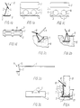
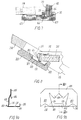
- the spring clip shown in Figs. la-ld and designated 10 in its entirety comprises a foot part 1 with barbs 2 at its sides. From one side of the foot part 1, an upright part 3 extends obliquely upwards and across the foot part, and at its far end in relation to the foot part 1, the upright part carries a catching fin 4 which extends obliquely downwards towards the foot part 1. A guide fin 5 extends oppositely to the catching fin 4 and in extension thereof.
- the spring clip may suitably be made of corrosion-resistant spring steel plate.
- the foot part 1 and the upright part 3 comprise openings 6 to adjust the rigidity of the spring clip 10.
Landscapes
- Engineering & Computer Science (AREA)
- General Engineering & Computer Science (AREA)
- Mechanical Engineering (AREA)
- Civil Engineering (AREA)
- Structural Engineering (AREA)
- Wood Science & Technology (AREA)
- Life Sciences & Earth Sciences (AREA)
- Clamps And Clips (AREA)
- Paper (AREA)
- Basic Packing Technique (AREA)
- Seal Device For Vehicle (AREA)
- Connection Of Plates (AREA)
- Crystals, And After-Treatments Of Crystals (AREA)
- Polarising Elements (AREA)
Abstract
Description
Claims (11)
- A fastening device comprising a spring clip device (10, 110, 210) comprising a foot part (1, 101, 201) with an upright part (3, 103) extending obliquely upwards in relation to and in over the foot part (1, 101, 201), wherein at a distance from the foot part (1, 101, 201), a catching fin (4, 104) extends obliquely downwards from the upright part (3, 103) to the same side as the foot part (1, 101, 201), characterized in that the foot part (1, 101, 201) is provided with barbs (2, 102, 202) extending outwardly and upwardly at at least one of its sides.
- A fastening device according to claim 1, characterized in that the upright part (3, 103) extends from one side of the foot part (1, 101).
- A fastening device according to claim 1-2, characterized in that a guide fin (5) extends oppositely to the catching fin (4).
- A fastening device according to claim 1, characterized in that at the two sides of the foot part (101), the spring clip device (110) comprises parts (130, 131), which are adapted to abut the side surfaces of a plate (115, 215) to fix the foot part (101) in its direction of width in relation to the side edge of the plate.
- A fastening device according to claim 4, characterized in that the spring clip device comprises two separate members (110, 210), of which the first member (210) comprises the foot part (201) provided with barbs (202), and the second member (110) comprises the catching fin (104) and a secondary foot part (101) with the parts (130, 131) adapted for abutment against the side surfaces of the plate (215), that the first member (210) comprises a fin (219) extending from one side (220) of the foot part (201) across the foot part (201) substantially in parallel with it and past the other side (221) of the foot part (201), and that the secondary foot part (101) is adapted to receive and retain said fin (219) when the second member (110) has been arranged on the side edge of a plate (215).
- A fastening device according to claim 5, characterized in that the secondary foot part (101) comprises an opening (132) for insertion of the fin (219), and that the fin (219) is provided with knobs (222) for engagement with the rim of the opening (132).
- A fastening device according to claims 1-6, characterized in that the spring clip device (10) is made of spring steel plate and comprises recesses (6) to adjust its rigidity.
- An assembly comprising a building component, such as a window frame, a flashing slat, etc., a plate (15, 115, 215) and a fastening device, according to any of claims 1 to 7, for the plate (15, 115, 215), one side edge of which is inserted in a groove (7, 107, 207) in the building component, wherein the width of the groove is substantially larger than the thickness of the plate (15, 115, 215), and wherein one side surface of the plate (15, 115, 215) abuts one side wall of the groove (7, 107, 207), the spring clip device (10, 110, 210) of the fastening device pressing against the other side surface of the plate (15, 115, 215) and preventing movement of the plate (15, 115, 215) in a direction out of the groove (7, 107, 207) by means of the catching fin (4, 104) engaging with the other side surface of the plate (15, 15, 215), the foot part (1, 101, 201) of the spring clip device having a width substantially corresponding to the width of the groove (7, 107, 207) at its bottom , the barbs (2, 102, 202) at at least one of its sides, being adapted for penetrating into the side wall of the groove (7, 107, 207).
- An assembly according to claim 8, characterized in that the plate (15) comprises a slot (16) for receiving the catching fin (4).
- An assembly according to claims 8 or 9, characterized in that the side edge of the plate (15) is rounded at the side surface intended to abut the side wall of the groove (7).
- An assembly according to claims 8-10, characterized in comprising a soft sealing strip (17) laid down into the groove (7) beneath the side edge of the plate (15).
Applications Claiming Priority (3)
| Application Number | Priority Date | Filing Date | Title |
|---|---|---|---|
| DK494/93 | 1993-04-30 | ||
| DK49493 | 1993-04-30 | ||
| DK93494A DK49493D0 (en) | 1993-04-30 | 1993-04-30 | Fixing |
Publications (2)
| Publication Number | Publication Date |
|---|---|
| EP0622499A1 EP0622499A1 (en) | 1994-11-02 |
| EP0622499B1 true EP0622499B1 (en) | 1998-11-25 |
Family
ID=8094196
Family Applications (1)
| Application Number | Title | Priority Date | Filing Date |
|---|---|---|---|
| EP94610023A Expired - Lifetime EP0622499B1 (en) | 1993-04-30 | 1994-04-28 | A fastening device |
Country Status (4)
| Country | Link |
|---|---|
| EP (1) | EP0622499B1 (en) |
| AT (1) | ATE173783T1 (en) |
| DE (1) | DE69414749T2 (en) |
| DK (1) | DK49493D0 (en) |
Families Citing this family (2)
| Publication number | Priority date | Publication date | Assignee | Title |
|---|---|---|---|---|
| US6706143B1 (en) * | 1996-03-19 | 2004-03-16 | International Paper Company | Minimizing chlorinated organics in pulp bleaching processes |
| DE29713539U1 (en) * | 1997-07-30 | 1997-09-25 | Diener, Horst, 89079 Ulm | Lock and key system |
Family Cites Families (4)
| Publication number | Priority date | Publication date | Assignee | Title |
|---|---|---|---|---|
| ZA743956B (en) * | 1974-06-20 | 1975-09-24 | H Bub | Improvements and relating to fastening clips |
| FR2571448A1 (en) * | 1984-10-04 | 1986-04-11 | Sedram Sa | Clip for the pinch-fastening of an air deflector to the door of a vehicle |
| EP0262282A1 (en) * | 1986-10-02 | 1988-04-06 | PICO-GLASS S.p.A. | Clamp suitable to secure two panels together to form a picture holder and apt to have a frame applied to it |
| FR2669202A1 (en) * | 1990-11-16 | 1992-05-22 | Bertry Richard | Framing system using trim pieces and springs [clips] that may belong to the glass mount |
-
1993
- 1993-04-30 DK DK93494A patent/DK49493D0/en not_active Application Discontinuation
-
1994
- 1994-04-28 DE DE69414749T patent/DE69414749T2/en not_active Expired - Lifetime
- 1994-04-28 AT AT94610023T patent/ATE173783T1/en not_active IP Right Cessation
- 1994-04-28 EP EP94610023A patent/EP0622499B1/en not_active Expired - Lifetime
Also Published As
| Publication number | Publication date |
|---|---|
| DE69414749D1 (en) | 1999-01-07 |
| DK49493A (en) | 1994-10-31 |
| ATE173783T1 (en) | 1998-12-15 |
| DE69414749T2 (en) | 1999-12-23 |
| EP0622499A1 (en) | 1994-11-02 |
| DK49493D0 (en) | 1993-04-30 |
Similar Documents
| Publication | Publication Date | Title |
|---|---|---|
| US4488391A (en) | Centering clips for window frames | |
| US4958792A (en) | Clip for supporting conduit and the like | |
| US4641474A (en) | Sta-put wallboard joiner | |
| US5653550A (en) | Retaining device for fastening an appliance insert in a base panel | |
| US5114105A (en) | Electrical box support bracket | |
| CA2251012C (en) | Height-adjusting element | |
| JPS58131419A (en) | Fixing device and combination of said fixing device and shape material | |
| US4819390A (en) | Supporting assemblies | |
| US5462349A (en) | Drawer with drawer side slide and drawer bottom | |
| WO1990004723A1 (en) | Fastening assembly and method of fastening | |
| US5090786A (en) | Drawer | |
| US5469681A (en) | Vinyl ceiling grid structure | |
| US4360285A (en) | Rail and post connector | |
| US5123225A (en) | Panel, clip and method of mounting panel | |
| JPH10169619A (en) | Fixing base plate for furniture hinge etc. | |
| CA1253316A (en) | Tool for fastening an elongated object on a supporting surface by means of u-shaped clips | |
| KR102072965B1 (en) | Stone Fastening Device | |
| EP0622499A1 (en) | A fastening device | |
| AU739513B2 (en) | Adjustable two-piece clip for mounting objects on a wall stud | |
| JPH0643788B2 (en) | Framed windows with grooves for inner panel members | |
| EP0913902B1 (en) | An electric box | |
| EP0470062B1 (en) | Method and element for connecting wooden walls | |
| GB2135044A (en) | Louvre and mullion system | |
| EP0864808B1 (en) | Mounting device for recessed lighting fixture | |
| JP3385323B2 (en) | Ceiling hanging hardware |
Legal Events
| Date | Code | Title | Description |
|---|---|---|---|
| PUAI | Public reference made under article 153(3) epc to a published international application that has entered the european phase |
Free format text: ORIGINAL CODE: 0009012 |
|
| AK | Designated contracting states |
Kind code of ref document: A1 Designated state(s): AT BE CH DE DK ES FR GB GR IE IT LI LU MC NL PT SE |
|
| RAX | Requested extension states of the european patent have changed |
Free format text: SI PAYMENT 940526 |
|
| 17P | Request for examination filed |
Effective date: 19950424 |
|
| 17Q | First examination report despatched |
Effective date: 19960905 |
|
| GRAG | Despatch of communication of intention to grant |
Free format text: ORIGINAL CODE: EPIDOS AGRA |
|
| GRAG | Despatch of communication of intention to grant |
Free format text: ORIGINAL CODE: EPIDOS AGRA |
|
| GRAH | Despatch of communication of intention to grant a patent |
Free format text: ORIGINAL CODE: EPIDOS IGRA |
|
| GRAH | Despatch of communication of intention to grant a patent |
Free format text: ORIGINAL CODE: EPIDOS IGRA |
|
| RAP1 | Party data changed (applicant data changed or rights of an application transferred) |
Owner name: VELUX INDUSTRI A/S |
|
| GRAA | (expected) grant |
Free format text: ORIGINAL CODE: 0009210 |
|
| AK | Designated contracting states |
Kind code of ref document: B1 Designated state(s): AT BE CH DE DK ES FR GB GR IE IT LI LU MC NL PT SE |
|
| AX | Request for extension of the european patent |
Free format text: SI PAYMENT 940526 |
|
| PG25 | Lapsed in a contracting state [announced via postgrant information from national office to epo] |
Ref country code: SE Free format text: THE PATENT HAS BEEN ANNULLED BY A DECISION OF A NATIONAL AUTHORITY Effective date: 19981125 Ref country code: NL Free format text: LAPSE BECAUSE OF FAILURE TO SUBMIT A TRANSLATION OF THE DESCRIPTION OR TO PAY THE FEE WITHIN THE PRESCRIBED TIME-LIMIT Effective date: 19981125 Ref country code: LI Free format text: LAPSE BECAUSE OF FAILURE TO SUBMIT A TRANSLATION OF THE DESCRIPTION OR TO PAY THE FEE WITHIN THE PRESCRIBED TIME-LIMIT Effective date: 19981125 Ref country code: IT Free format text: LAPSE BECAUSE OF FAILURE TO SUBMIT A TRANSLATION OF THE DESCRIPTION OR TO PAY THE FEE WITHIN THE PRESCRIBED TIME-LIMIT;WARNING: LAPSES OF ITALIAN PATENTS WITH EFFECTIVE DATE BEFORE 2007 MAY HAVE OCCURRED AT ANY TIME BEFORE 2007. THE CORRECT EFFECTIVE DATE MAY BE DIFFERENT FROM THE ONE RECORDED. Effective date: 19981125 Ref country code: GR Free format text: LAPSE BECAUSE OF NON-PAYMENT OF DUE FEES Effective date: 19981125 Ref country code: FR Free format text: LAPSE BECAUSE OF FAILURE TO SUBMIT A TRANSLATION OF THE DESCRIPTION OR TO PAY THE FEE WITHIN THE PRESCRIBED TIME-LIMIT Effective date: 19981125 Ref country code: ES Free format text: THE PATENT HAS BEEN ANNULLED BY A DECISION OF A NATIONAL AUTHORITY Effective date: 19981125 Ref country code: CH Free format text: LAPSE BECAUSE OF FAILURE TO SUBMIT A TRANSLATION OF THE DESCRIPTION OR TO PAY THE FEE WITHIN THE PRESCRIBED TIME-LIMIT Effective date: 19981125 Ref country code: BE Free format text: LAPSE BECAUSE OF FAILURE TO SUBMIT A TRANSLATION OF THE DESCRIPTION OR TO PAY THE FEE WITHIN THE PRESCRIBED TIME-LIMIT Effective date: 19981125 Ref country code: AT Free format text: LAPSE BECAUSE OF FAILURE TO SUBMIT A TRANSLATION OF THE DESCRIPTION OR TO PAY THE FEE WITHIN THE PRESCRIBED TIME-LIMIT Effective date: 19981125 |
|
| REF | Corresponds to: |
Ref document number: 173783 Country of ref document: AT Date of ref document: 19981215 Kind code of ref document: T |
|
| REG | Reference to a national code |
Ref country code: CH Ref legal event code: EP |
|
| REF | Corresponds to: |
Ref document number: 69414749 Country of ref document: DE Date of ref document: 19990107 |
|
| REG | Reference to a national code |
Ref country code: IE Ref legal event code: FG4D |
|
| PG25 | Lapsed in a contracting state [announced via postgrant information from national office to epo] |
Ref country code: PT Free format text: LAPSE BECAUSE OF FAILURE TO SUBMIT A TRANSLATION OF THE DESCRIPTION OR TO PAY THE FEE WITHIN THE PRESCRIBED TIME-LIMIT Effective date: 19990225 Ref country code: DK Free format text: LAPSE BECAUSE OF FAILURE TO SUBMIT A TRANSLATION OF THE DESCRIPTION OR TO PAY THE FEE WITHIN THE PRESCRIBED TIME-LIMIT Effective date: 19990225 |
|
| EN | Fr: translation not filed | ||
| PG25 | Lapsed in a contracting state [announced via postgrant information from national office to epo] |
Ref country code: LU Free format text: LAPSE BECAUSE OF NON-PAYMENT OF DUE FEES Effective date: 19990428 Ref country code: IE Free format text: LAPSE BECAUSE OF NON-PAYMENT OF DUE FEES Effective date: 19990428 Ref country code: GB Free format text: LAPSE BECAUSE OF NON-PAYMENT OF DUE FEES Effective date: 19990428 |
|
| NLV1 | Nl: lapsed or annulled due to failure to fulfill the requirements of art. 29p and 29m of the patents act | ||
| REG | Reference to a national code |
Ref country code: CH Ref legal event code: PL |
|
| PLBE | No opposition filed within time limit |
Free format text: ORIGINAL CODE: 0009261 |
|
| STAA | Information on the status of an ep patent application or granted ep patent |
Free format text: STATUS: NO OPPOSITION FILED WITHIN TIME LIMIT |
|
| PG25 | Lapsed in a contracting state [announced via postgrant information from national office to epo] |
Ref country code: MC Free format text: LAPSE BECAUSE OF NON-PAYMENT OF DUE FEES Effective date: 19991031 |
|
| 26N | No opposition filed | ||
| GBPC | Gb: european patent ceased through non-payment of renewal fee |
Effective date: 19990428 |
|
| REG | Reference to a national code |
Ref country code: IE Ref legal event code: MM4A |
|
| PGFP | Annual fee paid to national office [announced via postgrant information from national office to epo] |
Ref country code: DE Payment date: 20100423 Year of fee payment: 17 |
|
| REG | Reference to a national code |
Ref country code: DE Ref legal event code: R119 Ref document number: 69414749 Country of ref document: DE |
|
| REG | Reference to a national code |
Ref country code: DE Ref legal event code: R119 Ref document number: 69414749 Country of ref document: DE |
|
| PG25 | Lapsed in a contracting state [announced via postgrant information from national office to epo] |
Ref country code: DE Free format text: LAPSE BECAUSE OF FAILURE TO SUBMIT A TRANSLATION OF THE DESCRIPTION OR TO PAY THE FEE WITHIN THE PRESCRIBED TIME-LIMIT Effective date: 20111031 |