EP0621186B1 - Double clippers for continuously forming link product - Google Patents
Double clippers for continuously forming link product Download PDFInfo
- Publication number
- EP0621186B1 EP0621186B1 EP94108918A EP94108918A EP0621186B1 EP 0621186 B1 EP0621186 B1 EP 0621186B1 EP 94108918 A EP94108918 A EP 94108918A EP 94108918 A EP94108918 A EP 94108918A EP 0621186 B1 EP0621186 B1 EP 0621186B1
- Authority
- EP
- European Patent Office
- Prior art keywords
- clip
- clips
- channels
- clipper
- rail
- Prior art date
- Legal status (The legal status is an assumption and is not a legal conclusion. Google has not performed a legal analysis and makes no representation as to the accuracy of the status listed.)
- Expired - Lifetime
Links
- 208000019300 CLIPPERS Diseases 0.000 title claims description 80
- 208000021930 chronic lymphocytic inflammation with pontine perivascular enhancement responsive to steroids Diseases 0.000 title claims description 80
- 230000007246 mechanism Effects 0.000 claims description 26
- 230000009977 dual effect Effects 0.000 claims description 14
- 230000033001 locomotion Effects 0.000 claims description 12
- 239000002184 metal Substances 0.000 claims description 11
- 230000009471 action Effects 0.000 claims description 5
- 241000269319 Squalius cephalus Species 0.000 claims description 3
- 230000037361 pathway Effects 0.000 claims description 3
- 230000015572 biosynthetic process Effects 0.000 claims description 2
- 238000004806 packaging method and process Methods 0.000 description 15
- 239000000463 material Substances 0.000 description 12
- 238000010276 construction Methods 0.000 description 5
- 238000010586 diagram Methods 0.000 description 4
- 239000012530 fluid Substances 0.000 description 4
- 238000004519 manufacturing process Methods 0.000 description 4
- 230000008859 change Effects 0.000 description 3
- 235000013305 food Nutrition 0.000 description 3
- 230000008030 elimination Effects 0.000 description 2
- 238000003379 elimination reaction Methods 0.000 description 2
- 235000013580 sausages Nutrition 0.000 description 2
- 238000007789 sealing Methods 0.000 description 2
- 230000001154 acute effect Effects 0.000 description 1
- 230000004075 alteration Effects 0.000 description 1
- 238000005452 bending Methods 0.000 description 1
- 235000013351 cheese Nutrition 0.000 description 1
- 230000003749 cleanliness Effects 0.000 description 1
- 239000003292 glue Substances 0.000 description 1
- 238000012423 maintenance Methods 0.000 description 1
- 229920000728 polyester Polymers 0.000 description 1
- 230000002265 prevention Effects 0.000 description 1
- 230000008439 repair process Effects 0.000 description 1
- 230000000717 retained effect Effects 0.000 description 1
- 238000012163 sequencing technique Methods 0.000 description 1
- 230000011664 signaling Effects 0.000 description 1
- 229910001220 stainless steel Inorganic materials 0.000 description 1
- 239000010935 stainless steel Substances 0.000 description 1
- 239000000725 suspension Substances 0.000 description 1
Images




Classifications
-
- B—PERFORMING OPERATIONS; TRANSPORTING
- B65—CONVEYING; PACKING; STORING; HANDLING THIN OR FILAMENTARY MATERIAL
- B65B—MACHINES, APPARATUS OR DEVICES FOR, OR METHODS OF, PACKAGING ARTICLES OR MATERIALS; UNPACKING
- B65B9/00—Enclosing successive articles, or quantities of material, e.g. liquids or semiliquids, in flat, folded, or tubular webs of flexible sheet material; Subdividing filled flexible tubes to form packages
- B65B9/10—Enclosing successive articles, or quantities of material, in preformed tubular webs, or in webs formed into tubes around filling nozzles, e.g. extruded tubular webs
- B65B9/15—Enclosing successive articles, or quantities of material, in preformed tubular webs, or in webs formed into tubes around filling nozzles, e.g. extruded tubular webs the preformed tubular webs being stored on filling nozzles
-
- A—HUMAN NECESSITIES
- A22—BUTCHERING; MEAT TREATMENT; PROCESSING POULTRY OR FISH
- A22C—PROCESSING MEAT, POULTRY, OR FISH
- A22C11/00—Sausage making ; Apparatus for handling or conveying sausage products during manufacture
- A22C11/10—Apparatus for twisting or linking sausages
- A22C11/108—Apparatus for twisting or linking sausages with dividing elements located on the surface of a single rotary member
-
- B—PERFORMING OPERATIONS; TRANSPORTING
- B65—CONVEYING; PACKING; STORING; HANDLING THIN OR FILAMENTARY MATERIAL
- B65B—MACHINES, APPARATUS OR DEVICES FOR, OR METHODS OF, PACKAGING ARTICLES OR MATERIALS; UNPACKING
- B65B51/00—Devices for, or methods of, sealing or securing package folds or closures; Devices for gathering or twisting wrappers, or necks of bags
- B65B51/04—Applying separate sealing or securing members, e.g. clips
-
- B—PERFORMING OPERATIONS; TRANSPORTING
- B65—CONVEYING; PACKING; STORING; HANDLING THIN OR FILAMENTARY MATERIAL
- B65B—MACHINES, APPARATUS OR DEVICES FOR, OR METHODS OF, PACKAGING ARTICLES OR MATERIALS; UNPACKING
- B65B59/00—Arrangements to enable machines to handle articles of different sizes, to produce packages of different sizes, to vary the contents of packages, to handle different types of packaging material, or to give access for cleaning or maintenance purposes
- B65B59/04—Machines constructed with readily-detachable units or assemblies, e.g. to facilitate maintenance
-
- Y—GENERAL TAGGING OF NEW TECHNOLOGICAL DEVELOPMENTS; GENERAL TAGGING OF CROSS-SECTIONAL TECHNOLOGIES SPANNING OVER SEVERAL SECTIONS OF THE IPC; TECHNICAL SUBJECTS COVERED BY FORMER USPC CROSS-REFERENCE ART COLLECTIONS [XRACs] AND DIGESTS
- Y10—TECHNICAL SUBJECTS COVERED BY FORMER USPC
- Y10T—TECHNICAL SUBJECTS COVERED BY FORMER US CLASSIFICATION
- Y10T29/00—Metal working
- Y10T29/53—Means to assemble or disassemble
- Y10T29/53709—Overedge assembling means
- Y10T29/53787—Binding or covering
Definitions
- This invention relates to double clippers for continuously forming link product.
- the double clippers are suitable for use with a packaging device for filling formed and sealed tubular materials with pumpable products such as food products and for attaching double metal clips to the casing at intervals thereby enclosing or sealing the product in link form.
- US-A-3,383,754 discloses a device especially adapted for applying U-shaped metal clips about casing. Specifically, this patent teaches the use of a punch for driving a U-shaped metal clip down a channel against a die to thereby form the clip about gathered casing retained at the bottom of the clip channel.
- US-A-3,543,378 discloses the use of a pair of clippers arranged in tandem and cooperative with opposed movable casing gathering plates that define a pair of clip channels. The gathering plates move in opposition to each other to gather casing material into a constricted form or mass. Two U-shaped metal clips are then driven by punches about the gathered casing to seal the ends of the casing. A knife then cuts the casing between the clips to thereby separate the links defined by the clipped casing.
- US-A-3,583,056 discloses another clip attachment apparatus wherein a movable jaw pivots against a fixed jaw to gather the casing in a constricted region prior to attachment of a clip about the casing. Other patents disclose various combinations of gathering mechanisms for gathering casing prior to attachment of a clip or clips including US-A-3,783,583, US-A-4,001,926, and in US Reissue Patent No. 30,196.
- US-A-4,189,897 discloses a packaging device wherein product is placed in casing material and the material is then gathered and clipped by means of a U-shaped metal clip. Further, it discloses a continuous line operation device having a series of stations placed on an endless belt with means provided for each station to evacuate the casing, gather the casing, and attach a clip thereto.
- a packaging device for filing flexible, tubular casing is also known for the purposes of Article 54(3) EPC from WO-A-89/03346.
- This device uses clippers mounted at spaced intervals on a platform to engage the filed casing, attach clips and cut it into separate lengths.
- EP-A-0135238 discloses a dual clipper over which claim 1 has been characterised.
- a single clip apparatus is disclosed in DE-A-2410332 which includes a clip pusher mechanism.
- a dual clipper for attachment simultaneously of two spaced U-shaped metal clips about casing, for the formation of stuffed chub products, the clipper comprising:
- Such a clipper may be used in conjunction with the packaging device described in EP-A-0396723.
- FIGURES 1, 4-15 illustrate in great detail the construction of each clipper 212 and its unique components.
- Each clipper 212 on a packaging device for example as shown in FIGURES 2 and 3, has a substantially identical construction.
- the construction of the packaging device as described is not a limiting feature of the preferred clipper, which may be utilized in any of a number of packaging devices.
- an improved packaging device includes a mounting assembly 210 having supported thereon a plurality of clippers 212.
- Each clipper 212 is normally positioned at an equal radial distance from a vertical rotation axis 214 (see FIGURE 3).
- the axis 214 of the device 201 is associated with a mounting assembly central support post 232.
- a casing feed mechanism directs product from a stuffing machine through a horn, preferably made from stainless steel, and a casing brake into advancing casing, and by a chute into the device, tangentially with respect to the clippers 212 and axis 214 (see WO-A-89/03346 and EP-A-0396723 for more information in this regard).
- the filled casing 224 then extends into the throat 227 of one of the clippers 212 as that clipper 212 moves along a circular path about the axis 214. That clipper 212 gathers the casing material, applies two spaced metal clips about the gathered casing, severs the casing between the clips (if desired) and ultimately releases the formed casing product or link 225 for discharge from the device 220. Each clipper 212 so operates, as it rotates past the chute 228.
- the clippers 212 may each operate in the following sequence:
- the clippers 212 are equally spaced to one another and also equally radially spaced from the center axis 214.
- the clippers 212 may be moved inwardly and outwardly radially in a manner to be explained below. Generally the clippers 212 move in unison inwardly and outwardly toward and away from the axis 214. Alternate clippers 212 may be moved inwardly toward the axis 214 thus eliminating their use in the packaging operation.
- the radius or radial distance of the clippers 212 from the axis 214 is preferably a maximum to avoid flexure or bending of the casing.
- Hoses supplying fluid from the central column of the packaging device extend to the fluid actuated mechanisms of the clipper 212 other than the clip driving cylinders 352 (see FIGURE 1). Pressurized fluid is continuously available as a source of power from a remote source.
- all mechanisms of the preferred device are pneumatic, and the source of pressurized fluid is a source of pressurized air. Valves sweep past actuators (not shown) which cause the valves to trigger the mechanisms of the preferred device at rotational locations as desired. Because of the use of pneumatic mechanisms, cleanliness in the handling of food products is promoted.
- the clippers 212 are maintained in position by supporting wedge members such as member 338.
- the wedge members 338 significantly improve the packaging device by mounting the clippers 212 in true radial lines, for radial adjustment along such true radial lines, as opposed to the offset mounting of the device disclosed in WO-A-89/03346.
- a pair of vertically spaced, radially extending rails 353 define a radially extending slide channel 355 between the rails 353.
- the wedge plates 346 extend circumferentially, to define uniformly narrow, radially extending clipper passages such as 357.
- Each clipper 212 is individually movable radially for adjustment of product length, or elimination of clippers from action.
- each clipper While in use, each clipper is pinned in a clipper passage 357 by pins (not shown) placed in selected pin openings 362 along each set of rails 353. As in FIGURE 15, closely spaced openings on the clipper flanges 359 mate with the more distantly spaced openings 362 to provide clipper placement as desired within 1.6 mm (one sixteenth inch).
- Each clipper 212 is a double clipper and includes a single main vertical mounting unit of two die supports 260 (see FIGURES 1, 8).
- the mounting plate 260 is attached to the bracket 361 comprised of a horizontal plate and two underlying, spaced vertical members (see also FIGURE 8) and defines two vertical clip channels 262.
- the channels 262 are generally parallel.
- Each channel 262 is designed to receive a separate clip, has simultaneous operation, and defines a partial pathway for a clip driven by a punch 266.
- each channel 262 is partially open at its lower end to define a throat 227 for receipt of casing 224.
- the throat 227 is closed and defines a fully closed channel whenever a gate mechanism 285 is rotated to the closed position as described below.
- Die blocks such as 281 are situated at the end of each channel 262.
- a single clip rail 264 (see FIGURE 8) directs clips from a clip storage as described below through an appropriate window into each clip channel 262.
- the clipper 212 is a double clipper, it includes the single rail 264 on the outside of the channels 262 for attachment simultaneously of two narrowly spaced U-shaped metal clips about casing 24.
- a clip reel 366 mounted on each clipper 212 above the wedge members 338 feeds spooled clips into clip input tubes 368.
- the clip input tube 368 is angled from the horizontal to the vertical, and terminates just above the clip rail 264.
- a ramped portion 370 of the clip rail 264 increases in width, and eases entry of the clips onto the clip rail 264.
- a straight, vertical clip pusher portion 372 of the clip rail continues to a right angle 374, where the clip rail 264 ends in a horizontal clip rail portion 376. Clips as shown travel down the clip rail 264.
- the clip rail 264 is joined to a mounting block 378, which is aligned on pins 380 against the side of the main vertical mounting plate 260.
- a toggled, manual clamp mechanism 382 releasably secures the mounting block 378, and thereby the rail 264, to the side of the main mounting plate 260. Rapid change of the rail and attached structure, to be described, is provided in the event of need for repair.
- a clip pusher assembly 384 is mounted by bolts 386 (see FIGURE 4) to the clip rail 264.
- a support plate 388 supports a vertically acting, pneumatic clip pusher cylinder 390, which drives a pawl 392.
- the pawl 392 contacts the legs of clips as they move along the rail 264.
- Upward retraction of a rod 394 (see FIGURE 5) of the cylinder 390 ratchets the pawl 392 upward along the clips.
- Downward advancement off the rod 394 causes the pawl 392 to pivot inward against the legs off clips about a pawl pivot 396.
- a wheel 398 extends horizontally, adjacent the bottom, forward position of the pawl 392, is spring-biased horizontally toward the clips, and is mounted for rotation in one direction (clockwise in FIGURE 5) only.
- the wheel 398 advances in rotation as the pawl 392 advances, and by its pressure on the clips, retains the clips against rearward movement during rearward movement of the pawl 392. Clips are maintained at all times under the forward-directed force of the pawl 392 or the same force as maintained by the wheel 398.
- a leaf spring 698 also contacts the clips, and aids in prevention of rearward movement of the clips.
- a most preferred pawl 592 includes the particular advantages of an access of pivoting aligned relative to the clip pusher portion 372 of the clip rail in a parallel line with the access of the cylinder 390, and undercut 594 immediately adjacent the tip of the preferred pawl 592, and an angle as will be described.
- a reference line 596 is perpendicular to the clip pusher portion 372 of the clip rail.
- the angle of the most preferred pawl 592 is an angle relative to the reference line 596 of a reference line 598 passing between the pivot axis of the pawl 592 and the tip 600 of the pawl.
- the included angle between reference lines 596 and 598 is in the range of 45° to 60°.
- the most preferred pawl 592 while it pushes along the legs of the clips, pushes against the section of the legs closely adjacent the top of the clips, to prevent pivoting of the clips about their tops and possible wedging of the clips against other surfaces of the machinery. Also with the most preferred pawl 592, the clutch with its wheel 398 is eliminated.
- timing of the motion of the clip pusher and the punches 266 is coordinated. Release of pressure of the clip pusher assembly 384 during retraction of the cylinder 390 and movement of the pawl 592 away from the area of the clip rail portion 376 occurs only during the time in which punches 266 have passed a window 400 adjacent the horizontal clip rail portion 376. Pressure is reapplied in advance of the punches 266 retracting past the window 400. Movement of the gates causes reactuation of the cylinder 390 to advance the pawl 592 such that before the punches 266 retract past the window 400, pressure is applied to the clips by the pawl 592.
- a short rail 402 extends between the two clip channels 262, within a chamber 404 aligned with the window 400.
- An intermediate clip guide 892 is positioned above the rail 402.
- a ramped leading edge tops the window 400.
- the size and configuration of the short rail 402, the chamber 404 and the channels 262 adjacent the chamber 404 are closely maintained for proper performance of the clipper 212.
- the clips bridge the channels 262 as they await action of the punches 266.
- a clip 406 is suspended in a first channel 262 and a clip 408 is suspended in the second channel 262 at the intersection of the chamber 404 with the channels 262, until punches 266 drive the clips 406, 408 forward and downward, for clipping.
- the length of the short rail 402 is maintained equal to an integer number of clips, assuming each such clip is the minimum dimension permitted under the manufacturing tolerance, plus or minus the manufacturing tolerance times one. An integer number of seven is highly preferred.
- the height of the chamber 404 above the short rail 402, referred to hereafter as the "headroom”, is closely maintained to prevent locking, or wedging, of adjacent clips against each other due to vertical movement of the clips while under pressure of the pawl 392 and wheel 398.
- Clips with rectangular cross-sections along their spines should suffer little risk of locking.
- Clips with circular cross-sections along their spines present great risk of locking. Slight vertical movement will wedge such clips.
- Tipper Tie R trapezoidal clips present little risk of wedging when the headroom is maintained at less than half the vertical dimension between the bottom of the clip and the point along the periphery of the clip where the clip narrows.
- a chamfer 410 is placed on both sides 412, the top 414 and both angled portions 416 of the short rail 402, for centering the clips onto the short rail 402.
- Adjacent the short rail, the clip channels 262 have close tolerances relative to the punches 266; neither the punches 266 nor the clip channels 262 are maintained closely parallel to each other or dimensioned to prevent punch deflection.
- the punches 266 are driven by a pneumatic punch drive cylinder 268.
- Punches 266 are connected directly to a piston 420 of the punch drive cylinder 268. Return of the piston 420 upward is. provided by a return spring 422 acting between the punch cylinder piston 420 and the punch drive cylinder 268.
- a gathering gate cylinder 272 drives a gathering gate mechanism 285. Coordination of the punch and gate movements is provided by pneumatic controls, including a valve 424 positioned to sense movement of a plate 426 under action of the gathering mechanism 285. Gathering trips the valve 424, signalling for actuation of the clipper punch drive cylinder 268.
- a toggled backplate 428 (see also FIGURE 7) is positioned to abut clips such as clip 408 in the clip channel 262 opposite the clip rail 264, and when removed, provides quick access to the chamber 404 within which the short rail 402 resides.
- an ejection strap 700 is fastened pivotably to the gate and die support.
- the die support is well-rounded, at 702. The strap flexes out of the throat 227 when the gate is lowered, and flexes to eject product when the gate is raised.
- an improved clipper which includes a special carriage and gate construction for gathering casing material prior to attachment of a clip thereto, which is of a simplified construction and high speed operation relative to prior art clipper devices.
Landscapes
- Engineering & Computer Science (AREA)
- Mechanical Engineering (AREA)
- Life Sciences & Earth Sciences (AREA)
- Wood Science & Technology (AREA)
- Zoology (AREA)
- Food Science & Technology (AREA)
- Containers And Plastic Fillers For Packaging (AREA)
- Package Closures (AREA)
- Moulds For Moulding Plastics Or The Like (AREA)
- Treatment Of Fiber Materials (AREA)
- Dovetailed Work, And Nailing Machines And Stapling Machines For Wood (AREA)
Description
- This invention relates to double clippers for continuously forming link product. In particular, the double clippers are suitable for use with a packaging device for filling formed and sealed tubular materials with pumpable products such as food products and for attaching double metal clips to the casing at intervals thereby enclosing or sealing the product in link form.
- Various pumpable products, such as food products, and especially sausage or cheese, are packaged in tubular materials by attaching metal slips at spaced intervals thereby sealing and closing product within the tubular materials. US-A-3,383,754 discloses a device especially adapted for applying U-shaped metal clips about casing. Specifically, this patent teaches the use of a punch for driving a U-shaped metal clip down a channel against a die to thereby form the clip about gathered casing retained at the bottom of the clip channel.
- US-A-3,543,378 discloses the use of a pair of clippers arranged in tandem and cooperative with opposed movable casing gathering plates that define a pair of clip channels. The gathering plates move in opposition to each other to gather casing material into a constricted form or mass. Two U-shaped metal clips are then driven by punches about the gathered casing to seal the ends of the casing. A knife then cuts the casing between the clips to thereby separate the links defined by the clipped casing. US-A-3,583,056 discloses another clip attachment apparatus wherein a movable jaw pivots against a fixed jaw to gather the casing in a constricted region prior to attachment of a clip about the casing. Other patents disclose various combinations of gathering mechanisms for gathering casing prior to attachment of a clip or clips including US-A-3,783,583, US-A-4,001,926, and in US Reissue Patent No. 30,196.
- To increase the efficiency and utility of such clipping devices, it has been suggested in US-A-3,795,085 to mount a single clipper at a work station of a rotating table. A filled bag or casing which is to be clipped is placed on a nozzle at a first work station associated with the table. The casing material is then clamped as the table rotates to a second work station. Air in the casing is then evacuated through a vacuum system at a third station and ultimately, upon further rotation of the table to the clip work station, a clip is attached to the casing to seal the casing.
- In US-A-4,578,928 discloses yet another variation on this theme wherein a circular table is provided for gathering casing material fitted about a product and evacuating the casing material before finally placing a clip about the gathered casing material at a final work station. US-A-4,189,897 discloses a packaging device wherein product is placed in casing material and the material is then gathered and clipped by means of a U-shaped metal clip. Further, it discloses a continuous line operation device having a series of stations placed on an endless belt with means provided for each station to evacuate the casing, gather the casing, and attach a clip thereto.
- A packaging device for filing flexible, tubular casing is also known for the purposes of Article 54(3) EPC from WO-A-89/03346. This device uses clippers mounted at spaced intervals on a platform to engage the filed casing, attach clips and cut it into separate lengths.
- Two further clip apparatus are known. EP-A-0135238 discloses a dual clipper over which claim 1 has been characterised. A single clip apparatus is disclosed in DE-A-2410332 which includes a clip pusher mechanism.
- While the aforesaid devices have been useful, there has remained a need for a high speed continuously operable packaging device for attachment of metal clips to generally cylindrical, continuously filled casing.
- Such a need has been particularly acute with respect to the desire to form links of casing of variable length and diameter without major adjustment or alteration in the operation and configuration of the packaging device. Objectives of this general nature led to the development of the machine described in EP-A-0396723 (from which this case has been divided) which is especially useful for the manufacture of chubs and other sausage and link-type products having a wide variety of length and diameter.
- According to the present invention there is provided a dual clipper, for attachment simultaneously of two spaced U-shaped metal clips about casing, for the formation of stuffed chub products, the clipper comprising:
- a mounting unit defining two parallel clip channels, defining a window into the clip channels for receiving separated clips and a chamber aligned with the window, and defining a throat for receiving casing, the clip channels defining two partial pathways for clips driven by hereinafter defined punches;
- die means along the clip channels for deforming clips driven in the clip channels to the die means by the punches;
- dual clip punches movable in the clip channels past the window and chamber to the die means, for driving clips to the die means;
- punch drive means for driving the clip punches in the clip channels;
- a short rail extending between the clip channels in the chamber aligned with the window and defining an open space in each of the clip channels that are aligned with the rail; and
- clip rail means for directing clips through the
window and chamber into the clip channels, the clip rail
means directing clips into the clip channels from one
direction only,
characterised in that the dual clipper additionally comprises a gathering mechanism defining the throat in association with the clip channels, the gathering mechanism being movable to a closed position to close the throat, for the gathering of casing for clip attachment; - gathering drive means for driving the gathering mechanism to the closed position; and
- clip pusher means (a) for pushing clips along the
clip rail means towards the window, (b) for maintaining
the clips under forward-directed force during portions
of the times of clipper operation, and (c) for thereby
suspending clips in each of the open spaces of the two
clip channels by the forward-directed force in position
to be driven to the die means by the clip punches,
whereby the clips are suspended in the open spaces of the clip channels without need of an underlying bridging mechanism. -
- Such a clipper may be used in conjunction with the packaging device described in EP-A-0396723.
- An embodiment of the present invention will now be discussed by way of example only, and with reference to the accompanying drawings, in which:
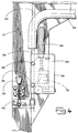
- FIGURE 1 is a side elevation of a preferred clipper;
- FIGURE 2 is a side elevation of the preferred packaging device employing clippers of FIGURE 1, shown with all but two clippers and clipper support brackets removed for illustration purposes (the two clippers shown are artificially suspended);
- FIGURE 3 is a perspective view of the packaging device of FIGURE 2;
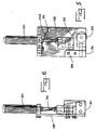
- FIGURE 4 is a detailed side elevation view of the clipper of FIGURE 1 from the side opposite that shown in FIGURE 1, showing the clip feed mechanism of the clipper;
- FIGURE 5 is a side elevation opposite that of FIGURE 4 of a clip pusher mechanism of the clip feed mechanism of FIGURE 4;
- FIGURE 6 is an end elevation of the clip pusher mechanism;
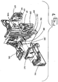
- FIGURE 7 is an exploded perspective view of the clip pusher mechanism;
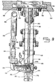
- FIGURE 8 is an outer end elevation view of the clipper of FIGURE 1;
- FIGURE 9 is a side elevation view of a short rail of the clipper, also shown in the exploded perspective of FIGURE 7 and the side elevation of FIGURE 8;
- FIGURE 10 is a plan view of the short rail;
- FIGURE 11 is an end elevation of the short rail;
- FIGURE 12 is a diagram of a most preferred clip pusher pawl of the preferred embodiment;
- FIGURE 13 is a further diagram of the most preferred pawl;
- FIGURE 14 is a still further diagram of the most preferred pawl, at a right angle to FIGURES 12 and 13; and
- FIGURE 15 is a diagram of clipper, wedge member openings and their cooperation.
-
- FIGURES 1, 4-15, illustrate in great detail the construction of each
clipper 212 and its unique components. Eachclipper 212 on a packaging device, for example as shown in FIGURES 2 and 3, has a substantially identical construction. However, it should be noted that the construction of the packaging device as described is not a limiting feature of the preferred clipper, which may be utilized in any of a number of packaging devices. - As shown in FIGURE 2, an improved packaging device includes a
mounting assembly 210 having supported thereon a plurality ofclippers 212. Eachclipper 212 is normally positioned at an equal radial distance from a vertical rotation axis 214 (see FIGURE 3). Theaxis 214 of the device 201 is associated with a mounting assemblycentral support post 232. A casing feed mechanism directs product from a stuffing machine through a horn, preferably made from stainless steel, and a casing brake into advancing casing, and by a chute into the device, tangentially with respect to theclippers 212 and axis 214 (see WO-A-89/03346 and EP-A-0396723 for more information in this regard). - The filled casing 224 then extends into the
throat 227 of one of theclippers 212 as thatclipper 212 moves along a circular path about theaxis 214. Thatclipper 212 gathers the casing material, applies two spaced metal clips about the gathered casing, severs the casing between the clips (if desired) and ultimately releases the formed casing product or link 225 for discharge from the device 220. Eachclipper 212 so operates, as it rotates past the chute 228. - As shown, for example, in the device of WO-A-89/03346, the
clippers 212 may each operate in the following sequence: - (a) The
clipper 212 initiates the casing gathering operation whenclipper 212 has rotated approximately 52° aboutaxis 214 from the starting point of the product feeding horn; - (b) A
clipper gathering gate 285 then pivots to gather the casing 224 in a tightly compacted configuration at approximately 68° rotation aboutaxis 214; - (c) At approximately 91°, or one quarter turn about
axis 214, aclipper punch 266 is actuated to engage a clip and drive that clip about the casing and against adie 281 to seal the casing; - (d) At approximately 164° of rotation about
axis 214, a knife severs the casing 224 between parallel closely attached clips to sever a forward link of the product filled casing from the remainder of the casing; - (e) At approximately 183° of rotation about
axis 214, the knife is retracted as is thepunch 266; - (f) At approximately 222° of rotation about
axis 214 thegate 285 is retracted and the device is readied for further use. At the same time an ejector mechanism acts to discharge the finished packaged product from the device. -
- The
clippers 212 are equally spaced to one another and also equally radially spaced from thecenter axis 214. Theclippers 212 may be moved inwardly and outwardly radially in a manner to be explained below. Generally theclippers 212 move in unison inwardly and outwardly toward and away from theaxis 214.Alternate clippers 212 may be moved inwardly toward theaxis 214 thus eliminating their use in the packaging operation. By adjusting the radius position of thevarious clippers 212, it is thus possible to change the distance betweenrespective clippers 212 and thus change the length of any link formed from the casing and its contents. However, preferably the radius or radial distance of theclippers 212 from theaxis 214 is preferably a maximum to avoid flexure or bending of the casing. - Hoses supplying fluid from the central column of the packaging device (not shown) extend to the fluid actuated mechanisms of the
clipper 212 other than the clip driving cylinders 352 (see FIGURE 1). Pressurized fluid is continuously available as a source of power from a remote source. - As most preferred, all mechanisms of the preferred device are pneumatic, and the source of pressurized fluid is a source of pressurized air. Valves sweep past actuators (not shown) which cause the valves to trigger the mechanisms of the preferred device at rotational locations as desired. Because of the use of pneumatic mechanisms, cleanliness in the handling of food products is promoted.
- Referring to FIGURES 2, 3, (for more detailed information in this regard, see EP-A-0396723 and its FIGURES 3, 4, 5, 11, 12, 13, 14), and especially to FIGURE 3, the
clippers 212 are maintained in position by supporting wedge members such asmember 338. Thewedge members 338 significantly improve the packaging device by mounting theclippers 212 in true radial lines, for radial adjustment along such true radial lines, as opposed to the offset mounting of the device disclosed in WO-A-89/03346. - Along each radially extending side of a
wedge plate 346 located on thewedge members 338, a pair of vertically spaced, radially extendingrails 353 define a radially extendingslide channel 355 between therails 353. As in FIGURE 3, thewedge plates 346 extend circumferentially, to define uniformly narrow, radially extending clipper passages such as 357. Referring to FIGURE 8,flanges 359 along theclippers 212, formed by aplate 361, ride in theslide channel 355, and theclippers 212 are slidable in theclipper passages 357. Eachclipper 212 is individually movable radially for adjustment of product length, or elimination of clippers from action. While in use, each clipper is pinned in aclipper passage 357 by pins (not shown) placed in selectedpin openings 362 along each set ofrails 353. As in FIGURE 15, closely spaced openings on theclipper flanges 359 mate with the more distantly spacedopenings 362 to provide clipper placement as desired within 1.6 mm (one sixteenth inch). - Each
clipper 212 is a double clipper and includes a single main vertical mounting unit of two die supports 260 (see FIGURES 1, 8). The mountingplate 260 is attached to thebracket 361 comprised of a horizontal plate and two underlying, spaced vertical members (see also FIGURE 8) and defines twovertical clip channels 262. Thechannels 262 are generally parallel. Eachchannel 262 is designed to receive a separate clip, has simultaneous operation, and defines a partial pathway for a clip driven by apunch 266. Thus, eachchannel 262 is partially open at its lower end to define athroat 227 for receipt of casing 224. Thethroat 227 is closed and defines a fully closed channel whenever agate mechanism 285 is rotated to the closed position as described below. Die blocks such as 281 are situated at the end of eachchannel 262. A single clip rail 264 (see FIGURE 8) directs clips from a clip storage as described below through an appropriate window into eachclip channel 262. - While the
clipper 212 is a double clipper, it includes thesingle rail 264 on the outside of thechannels 262 for attachment simultaneously of two narrowly spaced U-shaped metal clips about casing 24. - Referring to FIGURE 2, a
clip reel 366 mounted on eachclipper 212 above thewedge members 338 feeds spooled clips intoclip input tubes 368. As in FIGURE 8, theclip input tube 368 is angled from the horizontal to the vertical, and terminates just above theclip rail 264. A rampedportion 370 of theclip rail 264 increases in width, and eases entry of the clips onto theclip rail 264. A straight, verticalclip pusher portion 372 of the clip rail continues to aright angle 374, where theclip rail 264 ends in a horizontalclip rail portion 376. Clips as shown travel down theclip rail 264. - Referring to FIGURE 7, the
clip rail 264 is joined to amounting block 378, which is aligned onpins 380 against the side of the main vertical mountingplate 260. A toggled,manual clamp mechanism 382 releasably secures the mountingblock 378, and thereby therail 264, to the side of the main mountingplate 260. Rapid change of the rail and attached structure, to be described, is provided in the event of need for repair. - Referring to FIGURES 4-6, a
clip pusher assembly 384 is mounted by bolts 386 (see FIGURE 4) to theclip rail 264. Asupport plate 388 supports a vertically acting, pneumaticclip pusher cylinder 390, which drives apawl 392. Thepawl 392 contacts the legs of clips as they move along therail 264. Upward retraction of a rod 394 (see FIGURE 5) of thecylinder 390 ratchets thepawl 392 upward along the clips. Downward advancement off therod 394 causes thepawl 392 to pivot inward against the legs off clips about apawl pivot 396. So pivoted, thepawl 392 catches between the legs off the clips, and drives them forward, downward and into theclipper 212. Awheel 398 extends horizontally, adjacent the bottom, forward position of thepawl 392, is spring-biased horizontally toward the clips, and is mounted for rotation in one direction (clockwise in FIGURE 5) only. Thewheel 398 advances in rotation as thepawl 392 advances, and by its pressure on the clips, retains the clips against rearward movement during rearward movement of thepawl 392. Clips are maintained at all times under the forward-directed force of thepawl 392 or the same force as maintained by thewheel 398. Aleaf spring 698 also contacts the clips, and aids in prevention of rearward movement of the clips. - Referring to FIGURES 12 and 13, a most
preferred pawl 592 includes the particular advantages of an access of pivoting aligned relative to theclip pusher portion 372 of the clip rail in a parallel line with the access of thecylinder 390, and undercut 594 immediately adjacent the tip of thepreferred pawl 592, and an angle as will be described. Areference line 596 is perpendicular to theclip pusher portion 372 of the clip rail. The angle of the mostpreferred pawl 592 is an angle relative to thereference line 596 of areference line 598 passing between the pivot axis of thepawl 592 and thetip 600 of the pawl. The included angle betweenreference lines preferred pawl 592, while it pushes along the legs of the clips, pushes against the section of the legs closely adjacent the top of the clips, to prevent pivoting of the clips about their tops and possible wedging of the clips against other surfaces of the machinery. Also with the mostpreferred pawl 592, the clutch with itswheel 398 is eliminated. - With elimination of the clutch, timing of the motion of the clip pusher and the
punches 266 is coordinated. Release of pressure of theclip pusher assembly 384 during retraction of thecylinder 390 and movement of thepawl 592 away from the area of theclip rail portion 376 occurs only during the time in which punches 266 have passed awindow 400 adjacent the horizontalclip rail portion 376. Pressure is reapplied in advance of thepunches 266 retracting past thewindow 400. Movement of the gates causes reactuation of thecylinder 390 to advance thepawl 592 such that before thepunches 266 retract past thewindow 400, pressure is applied to the clips by thepawl 592. - As clips leave the
rail 264, they enter into theclip channels 262 through a window 400 (see FIGURE 7). Within the main vertical mountingplate 260, ashort rail 402 extends between the twoclip channels 262, within achamber 404 aligned with thewindow 400. Anintermediate clip guide 892 is positioned above therail 402. A ramped leading edge tops thewindow 400. The size and configuration of theshort rail 402, thechamber 404 and thechannels 262 adjacent thechamber 404 are closely maintained for proper performance of theclipper 212. As shown in FIGURE 7, the clips bridge thechannels 262 as they await action of thepunches 266. Aclip 406 is suspended in afirst channel 262 and aclip 408 is suspended in thesecond channel 262 at the intersection of thechamber 404 with thechannels 262, untilpunches 266 drive theclips - As fed down the
rail 264, the clips are joined along their spines, in the manner of paper clips, by a glue or tape. Polyester tape has been found most desirable for its clean breaks by theclippers 212 and lack of residue within theclippers 212. Suspension of theclips punches 266, the remaining clips are separated until any clip in the position ofclip 408 is not connected to any other clip, and any clip in the position ofclip 406 is connected only to incoming clips. If pressure were released by absence of thewheel 398, except withpawl 592 and proper sequencing of thepawl 592 and punches 266,clip 408 would likely fall from a suspended position and clip 406 would likely be misaligned. Thus, an important function of theclip pusher mechanism 384, including especiallypawl 392 andwheel 398, is maintenance of constant pressure on the incoming clips against clips suspended in theclip channels 262. - Accurate placement of clips in the
clip channels 262 is necessary to assure thepunches 266 do not sever or damage the clips, leaving residue of damage to block theclip channels 262. Accurate placement is assured by close control of spacing, as noted above. As most preferred, with Tipper TieR Trapezoidal™ clips, the length of theshort rail 402 is maintained equal to an integer number of clips, assuming each such clip is the minimum dimension permitted under the manufacturing tolerance, plus or minus the manufacturing tolerance times one. An integer number of seven is highly preferred. Also, the height of thechamber 404 above theshort rail 402, referred to hereafter as the "headroom", is closely maintained to prevent locking, or wedging, of adjacent clips against each other due to vertical movement of the clips while under pressure of thepawl 392 andwheel 398. Clips with rectangular cross-sections along their spines should suffer little risk of locking. Clips with circular cross-sections along their spines present great risk of locking. Slight vertical movement will wedge such clips. Tipper TieR trapezoidal clips present little risk of wedging when the headroom is maintained at less than half the vertical dimension between the bottom of the clip and the point along the periphery of the clip where the clip narrows. - A
chamfer 410 is placed on bothsides 412, the top 414 and bothangled portions 416 of theshort rail 402, for centering the clips onto theshort rail 402. Adjacent the short rail, theclip channels 262 have close tolerances relative to thepunches 266; neither thepunches 266 nor theclip channels 262 are maintained closely parallel to each other or dimensioned to prevent punch deflection. - Referring again to FIGURE 1, the
punches 266 are driven by a pneumaticpunch drive cylinder 268.Punches 266 are connected directly to apiston 420 of thepunch drive cylinder 268. Return of thepiston 420 upward is. provided by areturn spring 422 acting between thepunch cylinder piston 420 and thepunch drive cylinder 268. - A
gathering gate cylinder 272 drives agathering gate mechanism 285. Coordination of the punch and gate movements is provided by pneumatic controls, including avalve 424 positioned to sense movement of aplate 426 under action of thegathering mechanism 285. Gathering trips thevalve 424, signalling for actuation of the clipperpunch drive cylinder 268. - To free jams, if jams are encountered, a toggled backplate 428 (see also FIGURE 7) is positioned to abut clips such as
clip 408 in theclip channel 262 opposite theclip rail 264, and when removed, provides quick access to thechamber 404 within which theshort rail 402 resides. - For production ejection, an
ejection strap 700 is fastened pivotably to the gate and die support. For ease of passage of the gate in closing, the die support is well-rounded, at 702. The strap flexes out of thethroat 227 when the gate is lowered, and flexes to eject product when the gate is raised. - Thus, in at least the illustrated embodiment of the present invention, there is provided an improved clipper which includes a special carriage and gate construction for gathering casing material prior to attachment of a clip thereto, which is of a simplified construction and high speed operation relative to prior art clipper devices.
Claims (8)
- A dual clipper, for attachment simultaneously of two spaced U-shaped metal clips (406,408,409) about casing, for the formation of stuffed chub products, the clipper (212) comprising:a mounting unit (260) defining two parallel clip channels (262), defining a window (400) into the clip channels for receiving separated clips and a chamber (404) aligned with the window, and defining a throat (227) for receiving casing, the clip channels defining two partial pathways for clips driven by hereinafter defined punches (266);die means (281) along the clip channels for deforming clips driven in the clip channels to the die means by the punches;dual clip punches (266) movable in the clip channels past the window and chamber to the die means, for driving clips to the die means;punch drive means (268) for driving the clip punches in the clip channels;a short rail (402) extending between the clip channels in the chamber aligned with the window and defining an open space in each of the clip channels that are aligned with the rail; andclip rail means (264) for directing clips through the window and chamber into the clip channels, the clip rail means directing clips into the clip channels from one direction only,
characterised in that the dual clipper additionally comprises a gathering mechanism (285) defining the throat (227) in association with the clip channels (262), the gathering mechanism being movable to a closed position to close the throat, for the gathering of casing for clip attachment;gathering drive means (272) for driving the gathering mechanism to the closed position; andclip pusher means (384) (a) for pushing clips (409) along the clip rail means (264) towards the window (400), (b) for maintaining the clips under forward-directed force during portions of the times of clipper operation, and (c) for thereby suspending clips (406, 408) in each of the open spaces of the two clip channels (262) by the forward-directed force in position to be driven to the die means (281) by the clip punches (266),
whereby the clips (406,408) are suspended in the open spaces of the clip channels without need of an underlying bridging mechanism. - A dual clipper as claimed in claim 1, wherein the height of the chamber (404) above the short rail (402) is sized so as to prevent vertical movement and subsequent locking or wedging of the clips (406,408,409) in the chamber.
- A dual clipper as claimed in claim 1 or 2, wherein the short rail (402) has an upper surface which is shaped to receive trapezoidal clips.
- A dual clipper as in claim 1, 2 or 3 further comprising means for controlling the pushing action of the clip pusher means (384) and the driving action of the punch drive means (268) such that forward-directed force on clips (409) on the clip rail means (264) is maintained except as released only during times in which the clip punches (266) are past the window (400).
- A dual clipper as in any preceding claim, wherein the clip pusher means (384) includes a clipleg-contacting pawl (392) and reciprocating means (390,394) for intermittently driving the pawl to push clips (409) along the clip rail means (264).
- A dual clipper as in claim 5, wherein the clip pusher means (384) further includes a unidirectionally-rotatable wheel means (398) in contact with the clips (409) on the clip rail means (264).
- A dual clipper as in any preceding claim, wherein the short rail (402) has a length dimension, in the direction of clip movement along the short rail, of an integer number of clips (406,408,409).
- A dual clipper as claimed in claim 7, wherein the integer number is seven.
Applications Claiming Priority (3)
| Application Number | Priority Date | Filing Date | Title |
|---|---|---|---|
| US270222 | 1988-11-14 | ||
| US07/270,222 US5020298A (en) | 1987-10-07 | 1988-11-14 | Continuously rotating platform with multiple mounted double clippers for continuously forming link product |
| EP89913006A EP0396723B1 (en) | 1988-11-14 | 1989-11-09 | Continuously rotating platform with multiple mounted double clippers for continuously forming link product |
Related Parent Applications (2)
| Application Number | Title | Priority Date | Filing Date |
|---|---|---|---|
| EP89913006A Division EP0396723B1 (en) | 1988-11-14 | 1989-11-09 | Continuously rotating platform with multiple mounted double clippers for continuously forming link product |
| EP89913006.6 Division | 1989-11-09 |
Publications (2)
| Publication Number | Publication Date |
|---|---|
| EP0621186A1 EP0621186A1 (en) | 1994-10-26 |
| EP0621186B1 true EP0621186B1 (en) | 1999-03-17 |
Family
ID=23030421
Family Applications (2)
| Application Number | Title | Priority Date | Filing Date |
|---|---|---|---|
| EP89913006A Expired - Lifetime EP0396723B1 (en) | 1988-11-14 | 1989-11-09 | Continuously rotating platform with multiple mounted double clippers for continuously forming link product |
| EP94108918A Expired - Lifetime EP0621186B1 (en) | 1988-11-14 | 1989-11-09 | Double clippers for continuously forming link product |
Family Applications Before (1)
| Application Number | Title | Priority Date | Filing Date |
|---|---|---|---|
| EP89913006A Expired - Lifetime EP0396723B1 (en) | 1988-11-14 | 1989-11-09 | Continuously rotating platform with multiple mounted double clippers for continuously forming link product |
Country Status (8)
| Country | Link |
|---|---|
| US (1) | US5020298A (en) |
| EP (2) | EP0396723B1 (en) |
| JP (1) | JP2569223B2 (en) |
| AU (1) | AU618649B2 (en) |
| CA (1) | CA2002889C (en) |
| DE (2) | DE68928955T2 (en) |
| ES (1) | ES2016054A6 (en) |
| WO (1) | WO1990005671A2 (en) |
Families Citing this family (28)
| Publication number | Priority date | Publication date | Assignee | Title |
|---|---|---|---|---|
| US5259168A (en) * | 1987-10-07 | 1993-11-09 | Delaware Capital Formation, Inc. | Continuously rotating platform with multiple mounted double clippers for continuously forming link product |
| DE69109477T2 (en) * | 1991-01-30 | 1995-09-07 | Capital Formation Inc | Improved device for checking the constriction plates of a clamping device. |
| US5586424A (en) * | 1992-05-15 | 1996-12-24 | Delaware Capital Formation, Inc. | Apparatus for movement of U-shaped clips along a rail |
| US5890955A (en) * | 1995-08-29 | 1999-04-06 | Teepak Investments, Inc. | Zero time clipper roller conveyor |
| CA2175177A1 (en) * | 1995-08-29 | 1997-03-01 | Thomas Ralph Stanley | Zero time clipper |
| FR2753647A1 (en) * | 1996-09-25 | 1998-03-27 | Lenfant Nicole | Automatic sausage twisting and cutting machine |
| US6401885B1 (en) | 2000-10-03 | 2002-06-11 | Tipper Tie, Inc. | Internal brake mechanism for plastic film for a product filling machine |
| EP1421854B1 (en) * | 2002-11-22 | 2006-03-15 | Albert Handtmann Maschinenfabrik GmbH & Co. KG | Device with vacuum filler and a clipping machine |
| DE202004007722U1 (en) * | 2004-05-11 | 2005-09-22 | Tipper Tie Technopack Gmbh | Magazine holding closure staples for sausages, has second rail discharging onto path of first rail and forming closure over it |
| DE202007013669U1 (en) * | 2007-09-28 | 2009-02-12 | Tipper Tie Technopack Gmbh | Clip feed on round bars |
| US8006463B2 (en) * | 2007-12-19 | 2011-08-30 | Tipper Tie, Inc. | Rotating multi-clipper platform packaging systems |
| US9010072B2 (en) * | 2010-03-26 | 2015-04-21 | Tipper Tie, Inc. | Multiple station automated bagger systems, associated devices and related methods |
| CN102556433B (en) * | 2012-01-16 | 2014-06-11 | 石家庄成功机电有限公司 | Dual-clamp card puncher with single cylinder and single claw |
| WO2013166622A1 (en) | 2012-05-10 | 2013-11-14 | 石家庄成功机电有限公司 | Continuous disk-type clipper device |
| CN102658890B (en) * | 2012-05-10 | 2014-09-03 | 石家庄成功机电有限公司 | Continuous disc card punching equipment |
| CN103224071B (en) * | 2013-05-13 | 2014-12-17 | 瑞安市明瑞包装机械有限公司 | Multi-station processing paper plastic packaging machine |
| USD737352S1 (en) | 2013-08-09 | 2015-08-25 | Tipper Tie, Inc. | Spool mount for clippers on a rotating table |
| CN203806210U (en) * | 2013-08-09 | 2014-09-03 | 迪博泰有限公司 | Packaging system and roller mounting assemblies used for rotating packaging system |
| CN104627436A (en) * | 2013-11-08 | 2015-05-20 | 迪博泰有限公司 | Packaging systems with clip blow off and related clipper assemblies and methods |
| CN106477114A (en) | 2015-08-31 | 2017-03-08 | 迪博泰有限公司 | For having the cutter sweep of guillotine and the related packaging system cutting thermomechanical components |
| CN205738207U (en) | 2015-11-10 | 2016-11-30 | 迪博泰有限公司 | For the packaging system of low temperature explosive Emulsion and be suitable to the dihedral assembly of this system |
| CN105501556B (en) * | 2016-01-07 | 2017-11-21 | 河北晓进机械制造股份有限公司 | Mechanical bull double card sealing machine |
| US10889399B2 (en) * | 2016-10-28 | 2021-01-12 | Tipper Tie, Inc. | Packaging systems with clipper trigger and reset cam assemblies each comprising a plurality of cams and related cam assemblies |
| CN107628317A (en) * | 2017-09-28 | 2018-01-26 | 昆山精讯电子技术有限公司 | Adhesive tape cutting apparatus |
| CN117324964B (en) * | 2023-11-06 | 2026-04-07 | 中国船舶集团有限公司第七一九研究所 | Rib component rounding device |
| CN117324915A (en) * | 2023-11-06 | 2024-01-02 | 中国船舶集团有限公司第七一九研究所 | Large-scale cylindrical shell and rib ring automatic assembly device thereof |
| CN118602893B (en) * | 2024-06-17 | 2025-02-28 | 浙江瑞扬轴承科技有限公司 | Angular contact bearing protrusion measurement device and measurement method |
| CN120156741B (en) * | 2025-05-19 | 2025-08-01 | 大连安泰化工有限公司 | A protective device for a rotary buckle machine in an emulsion explosive production line |
Family Cites Families (20)
| Publication number | Priority date | Publication date | Assignee | Title |
|---|---|---|---|---|
| US1513265A (en) * | 1924-03-24 | 1924-10-28 | Offenhauser Christopher | Method of and apparatus for molding and linking sausages |
| US3264679A (en) * | 1963-12-24 | 1966-08-09 | Charles D Moekle | Apparatus for making linked products |
| US3383754A (en) * | 1967-01-10 | 1968-05-21 | Rheem Mfg Co | Fluid driven mechanism with protective stroke for applying a clip around a casing |
| US3543378A (en) * | 1968-09-11 | 1970-12-01 | Rheem Mfg Co | Clipping apparatus |
| US3583056A (en) * | 1968-09-16 | 1971-06-08 | Rheem Mfg Co | Clipping device |
| DE2018454B2 (en) * | 1970-04-17 | 1973-03-22 | Niedecker, Herbert, Dipl.-Ing., 6243 Falkenstein | METHOD AND DEVICE FOR BRAKING PACKAGING CASES WHICH LEAVE FROM A FILLING PIPE |
| US3795085A (en) * | 1972-01-20 | 1974-03-05 | Acraloc Corp | Device for the evacuation, clipping and trimming of bag-like packages |
| US3783583A (en) * | 1972-09-22 | 1974-01-08 | Rheem Mfg Co | Gathering means for clippers |
| DE2410332A1 (en) * | 1974-03-05 | 1975-09-11 | Niedecker Herbert | Bag and tube closing system - uses clips in strip fed off roll in synchronism with punch operation |
| US4004339A (en) * | 1975-04-07 | 1977-01-25 | Rheem Manufacturing Company | Single piston operated clip device |
| USRE30196E (en) * | 1975-04-07 | 1980-01-22 | Rheem Manufacturing Company | Single piston operated clip device |
| US4001926A (en) * | 1975-04-07 | 1977-01-11 | Rheem Manufacturing Company | Double clipper, single piston operated device |
| US4189897A (en) * | 1978-11-01 | 1980-02-26 | Acraloc Corporation | High speed evacuation chamber packaging and clipping machine |
| US4305240A (en) * | 1979-07-05 | 1981-12-15 | Domain Industries | Package forming and sealing apparatus |
| US4418447A (en) * | 1981-07-02 | 1983-12-06 | Devro, Inc. | Method and apparatus for processing stuffed sausage casing |
| US4463477A (en) * | 1981-07-02 | 1984-08-07 | Devro, Inc. | Apparatus for separating stuffed sausage links |
| US4420856A (en) * | 1981-07-02 | 1983-12-20 | Devro, Inc. | Apparatus for processing stuffed sausage casing |
| US4578928A (en) * | 1983-07-06 | 1986-04-01 | Acraloc Corporation | High speed evacuation chamber packaging machine and method |
| DE3333875A1 (en) * | 1983-09-20 | 1985-03-28 | Herbert Dipl.-Ing. 6240 Königstein Niedecker | DEVICE FOR CLOSING TUBULAR PACKING SLEEVES WITH U-SHAPED SEALING CLASPS |
| US4821485A (en) * | 1987-10-07 | 1989-04-18 | Delaware Capital Formation, Inc. | Continuously rotating platform with multiple mounted double clippers for continuously forming link product |
-
1988
- 1988-11-14 US US07/270,222 patent/US5020298A/en not_active Expired - Lifetime
-
1989
- 1989-08-16 ES ES8902869A patent/ES2016054A6/en not_active Expired - Fee Related
- 1989-11-09 WO PCT/US1989/005072 patent/WO1990005671A2/en not_active Ceased
- 1989-11-09 DE DE68928955T patent/DE68928955T2/en not_active Expired - Fee Related
- 1989-11-09 DE DE68922720T patent/DE68922720T2/en not_active Expired - Fee Related
- 1989-11-09 AU AU46431/89A patent/AU618649B2/en not_active Ceased
- 1989-11-09 EP EP89913006A patent/EP0396723B1/en not_active Expired - Lifetime
- 1989-11-09 JP JP2500411A patent/JP2569223B2/en not_active Expired - Fee Related
- 1989-11-09 EP EP94108918A patent/EP0621186B1/en not_active Expired - Lifetime
- 1989-11-14 CA CA002002889A patent/CA2002889C/en not_active Expired - Fee Related
Also Published As
| Publication number | Publication date |
|---|---|
| EP0621186A1 (en) | 1994-10-26 |
| ES2016054A6 (en) | 1990-10-01 |
| AU4643189A (en) | 1990-06-12 |
| WO1990005671A3 (en) | 1991-04-18 |
| EP0396723A1 (en) | 1990-11-14 |
| DE68928955T2 (en) | 1999-09-30 |
| WO1990005671A2 (en) | 1990-05-31 |
| DE68922720T2 (en) | 1996-01-18 |
| CA2002889A1 (en) | 1990-05-14 |
| CA2002889C (en) | 1997-01-07 |
| US5020298A (en) | 1991-06-04 |
| DE68922720D1 (en) | 1995-06-22 |
| AU618649B2 (en) | 1992-01-02 |
| JP2569223B2 (en) | 1997-01-08 |
| EP0396723B1 (en) | 1995-05-17 |
| JPH03503518A (en) | 1991-08-08 |
| DE68928955D1 (en) | 1999-04-22 |
Similar Documents
| Publication | Publication Date | Title |
|---|---|---|
| EP0396723B1 (en) | Continuously rotating platform with multiple mounted double clippers for continuously forming link product | |
| EP0333845B1 (en) | Continuously rotating platform with multiple mounted double clippers for continuously forming link product | |
| US5259168A (en) | Continuously rotating platform with multiple mounted double clippers for continuously forming link product | |
| US7665278B2 (en) | Methods for automatically packaging objects | |
| EP0352825A2 (en) | Packaging device using tubular casing | |
| CA1313123C (en) | Material positioning and securing apparatus and process |
Legal Events
| Date | Code | Title | Description |
|---|---|---|---|
| PUAI | Public reference made under article 153(3) epc to a published international application that has entered the european phase |
Free format text: ORIGINAL CODE: 0009012 |
|
| AC | Divisional application: reference to earlier application |
Ref document number: 396723 Country of ref document: EP |
|
| AK | Designated contracting states |
Kind code of ref document: A1 Designated state(s): CH DE FR GB IT LI NL SE |
|
| 17P | Request for examination filed |
Effective date: 19950425 |
|
| 17Q | First examination report despatched |
Effective date: 19960704 |
|
| GRAG | Despatch of communication of intention to grant |
Free format text: ORIGINAL CODE: EPIDOS AGRA |
|
| GRAG | Despatch of communication of intention to grant |
Free format text: ORIGINAL CODE: EPIDOS AGRA |
|
| GRAG | Despatch of communication of intention to grant |
Free format text: ORIGINAL CODE: EPIDOS AGRA |
|
| GRAH | Despatch of communication of intention to grant a patent |
Free format text: ORIGINAL CODE: EPIDOS IGRA |
|
| GRAH | Despatch of communication of intention to grant a patent |
Free format text: ORIGINAL CODE: EPIDOS IGRA |
|
| GRAA | (expected) grant |
Free format text: ORIGINAL CODE: 0009210 |
|
| AC | Divisional application: reference to earlier application |
Ref document number: 396723 Country of ref document: EP |
|
| AK | Designated contracting states |
Kind code of ref document: B1 Designated state(s): CH DE FR GB IT LI NL SE |
|
| PG25 | Lapsed in a contracting state [announced via postgrant information from national office to epo] |
Ref country code: SE Free format text: THE PATENT HAS BEEN ANNULLED BY A DECISION OF A NATIONAL AUTHORITY Effective date: 19990317 Ref country code: NL Free format text: LAPSE BECAUSE OF FAILURE TO SUBMIT A TRANSLATION OF THE DESCRIPTION OR TO PAY THE FEE WITHIN THE PRESCRIBED TIME-LIMIT Effective date: 19990317 |
|
| REG | Reference to a national code |
Ref country code: CH Ref legal event code: EP |
|
| REF | Corresponds to: |
Ref document number: 68928955 Country of ref document: DE Date of ref document: 19990422 |
|
| ET | Fr: translation filed | ||
| REG | Reference to a national code |
Ref country code: CH Ref legal event code: NV Representative=s name: E. BLUM & CO. PATENTANWAELTE |
|
| NLV1 | Nl: lapsed or annulled due to failure to fulfill the requirements of art. 29p and 29m of the patents act | ||
| PLBE | No opposition filed within time limit |
Free format text: ORIGINAL CODE: 0009261 |
|
| STAA | Information on the status of an ep patent application or granted ep patent |
Free format text: STATUS: NO OPPOSITION FILED WITHIN TIME LIMIT |
|
| 26N | No opposition filed | ||
| REG | Reference to a national code |
Ref country code: GB Ref legal event code: IF02 |
|
| PGFP | Annual fee paid to national office [announced via postgrant information from national office to epo] |
Ref country code: GB Payment date: 20031105 Year of fee payment: 15 |
|
| PGFP | Annual fee paid to national office [announced via postgrant information from national office to epo] |
Ref country code: FR Payment date: 20031110 Year of fee payment: 15 |
|
| PGFP | Annual fee paid to national office [announced via postgrant information from national office to epo] |
Ref country code: CH Payment date: 20031118 Year of fee payment: 15 Ref country code: DE Payment date: 20031118 Year of fee payment: 15 |
|
| PG25 | Lapsed in a contracting state [announced via postgrant information from national office to epo] |
Ref country code: GB Free format text: LAPSE BECAUSE OF NON-PAYMENT OF DUE FEES Effective date: 20041109 |
|
| PG25 | Lapsed in a contracting state [announced via postgrant information from national office to epo] |
Ref country code: LI Free format text: LAPSE BECAUSE OF NON-PAYMENT OF DUE FEES Effective date: 20041130 Ref country code: CH Free format text: LAPSE BECAUSE OF NON-PAYMENT OF DUE FEES Effective date: 20041130 |
|
| PG25 | Lapsed in a contracting state [announced via postgrant information from national office to epo] |
Ref country code: DE Free format text: LAPSE BECAUSE OF NON-PAYMENT OF DUE FEES Effective date: 20050601 |
|
| GBPC | Gb: european patent ceased through non-payment of renewal fee |
Effective date: 20041109 |
|
| REG | Reference to a national code |
Ref country code: CH Ref legal event code: PL |
|
| PG25 | Lapsed in a contracting state [announced via postgrant information from national office to epo] |
Ref country code: FR Free format text: LAPSE BECAUSE OF NON-PAYMENT OF DUE FEES Effective date: 20050729 |
|
| REG | Reference to a national code |
Ref country code: FR Ref legal event code: ST |
|
| PG25 | Lapsed in a contracting state [announced via postgrant information from national office to epo] |
Ref country code: IT Free format text: LAPSE BECAUSE OF NON-PAYMENT OF DUE FEES;WARNING: LAPSES OF ITALIAN PATENTS WITH EFFECTIVE DATE BEFORE 2007 MAY HAVE OCCURRED AT ANY TIME BEFORE 2007. THE CORRECT EFFECTIVE DATE MAY BE DIFFERENT FROM THE ONE RECORDED. Effective date: 20051109 |