EP0621068B1 - Method and apparatus for reducing the pressure of a high-pressure solids-gas stream - Google Patents
Method and apparatus for reducing the pressure of a high-pressure solids-gas stream Download PDFInfo
- Publication number
- EP0621068B1 EP0621068B1 EP94106333A EP94106333A EP0621068B1 EP 0621068 B1 EP0621068 B1 EP 0621068B1 EP 94106333 A EP94106333 A EP 94106333A EP 94106333 A EP94106333 A EP 94106333A EP 0621068 B1 EP0621068 B1 EP 0621068B1
- Authority
- EP
- European Patent Office
- Prior art keywords
- solids
- gas
- vessel
- recited
- pressure
- Prior art date
- Legal status (The legal status is an assumption and is not a legal conclusion. Google has not performed a legal analysis and makes no representation as to the accuracy of the status listed.)
- Expired - Lifetime
Links
- 238000000034 method Methods 0.000 title claims description 30
- 239000007787 solid Substances 0.000 claims abstract description 133
- 238000005243 fluidization Methods 0.000 claims abstract description 40
- 230000035699 permeability Effects 0.000 claims abstract description 8
- 239000000919 ceramic Substances 0.000 claims abstract description 6
- 238000001816 cooling Methods 0.000 claims description 9
- 238000007599 discharging Methods 0.000 claims description 9
- 238000001914 filtration Methods 0.000 claims description 3
- 238000000926 separation method Methods 0.000 abstract description 2
- 230000008569 process Effects 0.000 description 8
- 239000002245 particle Substances 0.000 description 5
- 230000009467 reduction Effects 0.000 description 5
- 238000006243 chemical reaction Methods 0.000 description 4
- 238000002309 gasification Methods 0.000 description 4
- 239000000463 material Substances 0.000 description 4
- 239000000203 mixture Substances 0.000 description 4
- 230000003247 decreasing effect Effects 0.000 description 3
- 239000011343 solid material Substances 0.000 description 3
- 230000008901 benefit Effects 0.000 description 2
- 230000015572 biosynthetic process Effects 0.000 description 2
- 238000002485 combustion reaction Methods 0.000 description 2
- 230000001419 dependent effect Effects 0.000 description 2
- 239000000446 fuel Substances 0.000 description 2
- 238000004891 communication Methods 0.000 description 1
- 238000007796 conventional method Methods 0.000 description 1
- 230000006866 deterioration Effects 0.000 description 1
- 230000001627 detrimental effect Effects 0.000 description 1
- 230000000694 effects Effects 0.000 description 1
- 238000012423 maintenance Methods 0.000 description 1
- 239000002184 metal Substances 0.000 description 1
- 230000001590 oxidative effect Effects 0.000 description 1
- 239000011236 particulate material Substances 0.000 description 1
- 230000037361 pathway Effects 0.000 description 1
- 238000012545 processing Methods 0.000 description 1
- 238000010926 purge Methods 0.000 description 1
- 238000013022 venting Methods 0.000 description 1
Images
Classifications
-
- F—MECHANICAL ENGINEERING; LIGHTING; HEATING; WEAPONS; BLASTING
- F23—COMBUSTION APPARATUS; COMBUSTION PROCESSES
- F23C—METHODS OR APPARATUS FOR COMBUSTION USING FLUID FUEL OR SOLID FUEL SUSPENDED IN A CARRIER GAS OR AIR
- F23C10/00—Fluidised bed combustion apparatus
- F23C10/18—Details; Accessories
- F23C10/24—Devices for removal of material from the bed
-
- B—PERFORMING OPERATIONS; TRANSPORTING
- B01—PHYSICAL OR CHEMICAL PROCESSES OR APPARATUS IN GENERAL
- B01D—SEPARATION
- B01D46/00—Filters or filtering processes specially modified for separating dispersed particles from gases or vapours
- B01D46/30—Particle separators, e.g. dust precipitators, using loose filtering material
-
- B—PERFORMING OPERATIONS; TRANSPORTING
- B01—PHYSICAL OR CHEMICAL PROCESSES OR APPARATUS IN GENERAL
- B01J—CHEMICAL OR PHYSICAL PROCESSES, e.g. CATALYSIS OR COLLOID CHEMISTRY; THEIR RELEVANT APPARATUS
- B01J8/00—Chemical or physical processes in general, conducted in the presence of fluids and solid particles; Apparatus for such processes
- B01J8/0015—Feeding of the particles in the reactor; Evacuation of the particles out of the reactor
- B01J8/003—Feeding of the particles in the reactor; Evacuation of the particles out of the reactor in a downward flow
-
- B—PERFORMING OPERATIONS; TRANSPORTING
- B01—PHYSICAL OR CHEMICAL PROCESSES OR APPARATUS IN GENERAL
- B01J—CHEMICAL OR PHYSICAL PROCESSES, e.g. CATALYSIS OR COLLOID CHEMISTRY; THEIR RELEVANT APPARATUS
- B01J8/00—Chemical or physical processes in general, conducted in the presence of fluids and solid particles; Apparatus for such processes
- B01J8/005—Separating solid material from the gas/liquid stream
- B01J8/006—Separating solid material from the gas/liquid stream by filtration
-
- B—PERFORMING OPERATIONS; TRANSPORTING
- B01—PHYSICAL OR CHEMICAL PROCESSES OR APPARATUS IN GENERAL
- B01J—CHEMICAL OR PHYSICAL PROCESSES, e.g. CATALYSIS OR COLLOID CHEMISTRY; THEIR RELEVANT APPARATUS
- B01J8/00—Chemical or physical processes in general, conducted in the presence of fluids and solid particles; Apparatus for such processes
- B01J8/008—Details of the reactor or of the particulate material; Processes to increase or to retard the rate of reaction
-
- F—MECHANICAL ENGINEERING; LIGHTING; HEATING; WEAPONS; BLASTING
- F23—COMBUSTION APPARATUS; COMBUSTION PROCESSES
- F23C—METHODS OR APPARATUS FOR COMBUSTION USING FLUID FUEL OR SOLID FUEL SUSPENDED IN A CARRIER GAS OR AIR
- F23C10/00—Fluidised bed combustion apparatus
- F23C10/16—Fluidised bed combustion apparatus specially adapted for operation at superatmospheric pressures, e.g. by the arrangement of the combustion chamber and its auxiliary systems inside a pressure vessel
Definitions
- This invention relates to a method and an apparatus for handling high pressure material, particularly to a method for reducing pressure of a high-pressure solids-gas mixture and for separating the solids from the solids-gas mixture in a vessel.
- the vessel is in communication with a reactor that is operated under a pressure of at least about 2 bars, and serves to maintain desired reactions, such as the combustion or gasification of fuel.
- the vessel serves to remove ash or other particulate material from the reactor.
- solids refers to all residues known to a person skilled in the art that may be obtained from reactions taking place in pressurized reactors, such as circulating fluidized bed reactors.
- the main set of components of the RPDS are depressurizing piping ("transporting pipe”), a de-entrainment vessel wherein a packed bed of solid material is maintained for acting as a solids flow restriction at the end of the transporting pipe, and means for controlling the flow of the solids from the de-entrainment vessel.
- An RPDS may be successfully utilized, for example, in connection with Pressurized Fluidized Bed reactors such as Pressurized Fluidized Bed Combustors or Gasifiers and processes executed therein.
- Pressurized Fluidized Bed reactors such as Pressurized Fluidized Bed Combustors or Gasifiers and processes executed therein.
- a Pressurized Fluidized Bed Gasifier which provides a partial gasification of fuel
- a Fluidized Bed Combustor for oxidizing the residue char from the gasification
- a transportation system for conveying the solids resulting from a partial gasification, such as char, to the final combustion
- Any corresponding processes can be equipped with an RPDS as well.
- the reactions take place at elevated pressure, e.g. 2 - 20 bar, and at elevated temperature, preferably about 1200°C, and residues are produced which should be subjected to further processing at lower pressure.
- the solids discharged from a Pressurized Fluidized Bed reactor may be introduced to the RPDS either with or without first cooling the solids. If cooling is utilized, the temperature of the solids may be lowered even to about 300°C temperature if the temperature of the solids-gas stream prior to introduction into the de-entrainment vessel is about 300-1200°C (e.g. about 300-799°C); otherwise, the temperature is still reduced to below that of the reactor, e.g. to about 800-1200°C.
- a necessary feature of the RPDS system in order to achieve continuous movement of the solids with a simultaneous pressure drop of the gas is to cause the gas to flow faster than the solids in the piping.
- the RPDS usually smoothly and reliably de-pressurizes the solids. It also has some advantages over a lockhopper as a depressurization device (e.g. the flow of the solids is continuous, and valve maintenance time and costs are decreased).
- the gas flow rate is increased to too great an extent, the whole de-pressurizing process is handicapped due to the fluidization of the solids in the de-entrainment vessel.
- EP 392 577 shows an ash discharging vessel connected to a pressurized combustor or gasifier. Ash is introduced into the vessel at intervals, the vessel thereby being pressurized. The vessel is de-pressurized between the ash introduction steps, before discharging ash therefrom. De-pressurizing takes place by venting gas through a de-pressurizing conduit.
- the de-pressurizing conduit comprises a gas permeable filter element allowing gas only to be discharged therethrough.
- the present invention is based on the problem of providing a method and an apparatus to ensure the proper function of a de-pressurization system utilizing an RPDS in various process situations.
- This object is solved according to the present invention by a method including the features of claim 1 and an apparatus including the features of claim 6. Detailed embodiments are described in the dependent claims.
- the present invention in a significant departure from the conventional system discussed above -- has solved the problem of deterioration of de-pressurization capability, even when the conditions under which fluidization would normally take place if the conventional technique existed, by preventing the possibility of fluidization of the solids. This is accomplished in accordance with the method of the present invention by decreasing the flow velocity of the gas prior to or when discharging the gas into the packed bed solids in the de-entrainment vessel.
- the cross sectional area of the opening through which the gas and solid streams are discharged into the bed of solids in the de-entrainment vessel is larger than the cross-sectional area of the pipe introducing the gas and solid streams into the de-entrainment vessel and used for pressure release of the gas.
- the reduction of the velocity of the gas discharging into the de-entrainment vessel is preferably accomplished immediately prior to or when discharge of the gas takes place since it is advantageous to maintain a higher velocity as long as possible in order to achieve a large enough pressure loss in the transporting pipe.
- the discharge of the gas-solids stream into the de-entrainment vessel can be designed to be optimal independently of the pressure reduction effects in the transporting pipe.
- a method of reducing the pressure of a high pressure solids-gas stream, and separating the solids from the solids-gas stream utilizes a de-entrainment vessel including a packed bed of solids, a solids outlet, a gas outlet above the level of the packed bed connected to a low pressure area, and an inlet for the solids-gas stream into the vessel.
- the method comprises the steps of substantially continuously: (a) Introducing the high pressure solids-gas stream into the de-entrainment vessel through the inlet so that the gas of the solids-gas stream flows faster than the solids, to provide a pressure drop of the gas.
- step (b) Causing the gas from the solids-gas stream of step (a) to flow through the packed bed of solids.
- step (c) Causing the velocity of the gas to decrease during, or just prior to, introduction of the gas into the packed bed of solids, to minimize the possibility of fluidization of the solids.
- step (d) Discharging the gas separated from the solids-gas stream, after it has passed through the packed bed, through the gas outlet and transporting it to a low pressure area; and (e) discharging solids from the vessel below the level of the packed bed.
- the temperature of the gas-solids stream, and bed solids is between about 800 - 1200°C.
- the gas-solids stream typically has a pressure of about 2-20 bar, and steps (d) and (e) are typically practiced to discharge the separated gas and solids to substantially atmospheric pressure areas.
- the method may also include the further step of dividing the solids-gas stream into a plurality of streams prior to step (b). There is also the additional step of further minimizing the possibility of fluidization of the solids by passing the gas, after or simultaneously with step (b), through an element permeable to gas but substantially impermeable to solids within the gas-solids stream or the packed bed.
- apparatus for reducing the pressure of a high pressure solids-gas stream and separating the solids from the solids-gas stream.
- the apparatus comprises the following elements: A substantially vertical de-entrainment vessel having a bed of packed solids therein, disposed at a level within the vessel, and a side wall; a transporting pipe having a first cross-sectional area and containing the solids-gas stream therein at a super-atmospheric pressure; inlet means connected to said transporting pipe, and disposed within the de-entrainment vessel, and including a discharge opening below the level of the bed of packed solids, the inlet means at the discharge opening having a second effective cross-sectional area significantly greater than the first cross-sectional area, so as to minimize the possibility of fluidization of the solids; a gas outlet from the vessel located above the level of the bed of solids, and connected to an area having a lower pressure than the pressure in the transporting pipe; and a solids outlet from the vessel located below the level of
- the inlet means may include a gradually expanding cross-sectional area section (e. g. a right circular cone) at the discharge opening.
- a plurality of openings may be provided in the cone, below the level of the packed solids bed, through which gas flows toward (that is with at least a velocity component toward) the vessel wall.
- the apparatus also further comprises additional means for substantially preventing fluidization, comprising a substantially gas permeable and substantially solids impermeable element operatively connected to the inlet means adjacent the discharge opening disposed in the pathway of gas from the inlet means to the gas outlet.
- the fluidization preventing means element may be directly connected to the inlet means adjacent the discharge opening, and extends from the inlet means toward the vessel wall; in fact, the fluidization preventing element may cover substantially the entire area between the inlet means and the vessel side wall, substantially defining the upper level of the packed bed of solids.
- the fluidization preventing element typically is selected from perforated plates, wire mesh screens, and filtering means (e. g. ceramic filters).
- the fluidization preventing element may also have uniform or varying gas permeability. For example, the gas permeability of the fluidization preventing element may be lowest closest to the inlet means, and greatest closest to the vessel side wall, and may gradually increase from the inlet means toward the vessel side wall.
- the transporting pipe may optionally comprise a single transporting pipe having the first cross-sectional area
- the inlet means may comprise a plurality of inlet elements connected to and branching from the single transporting pipe.
- the inlet elements collectively have a second cross-sectional area significantly greater than the first cross-sectional area.
- the solids outlet may comprise a plurality of outlet elements
- the gas outlet may comprise a plurality of outlet elements.
- the apparatus described above may be in combination with a pressurized fluidized bed reactor having a pressure of about 2-20 bar, and connected to the transporting pipe. Also, there is optionally a cooling means disposed between the reactor and the inlet means for cooling the temperature of the solids-gas stream to about 300-799°C.
- an apparatus for the same purpose comprising the following elements: A substantially vertical de-entrainment vessel having a bed of packed solids therein, disposed at a level within the vessel, and a side wall; a transporting pipe containing the solids-gas stream therein at a super-atmospheric pressure; inlet means connected to the transporting pipe, and disposed within the de-entrainment vessel, and including a discharge opening below the level of the bed of packed solids; a gas outlet from the vessel located above the level of the bed of solids, and connected to an area having a lower pressure than the pressure in the transporting pipe; a solids outlet from the vessel located below the level of the bed of solids, and connected to an area having a lower pressure than the pressure in the transporting pipe; and means for substantially preventing fluidization, comprising a substantially solids impermeable and a substantially gas permeable element operatively connected to the inlet means and extending toward the vessel side wall.
- the fluidization preventing means is
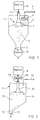
- the invention exemplary apparatus illustrated in FIG. 1 for conveying solid material particles in gas from higher pressure to lower, e.g. atmospheric, pressure, utilizing an RPDS comprises as a main component a vertical de-entrainment vessel 1, and means for conveying the solids and gas stream through transporting pipe 2 into the de-entrainment vessel 1.
- the transporting pipe 2 is operatively connected to a pressurized reactor, such as the pressurized fluidized bed reactor 10 shown schematically in FIG. 1, from which the stream of solids and gas is discharged.
- reactor 10 reactions take place at high pressure, e.g. about 2-20 bar, and at high temperature, e.g. about 1200°C.
- the gas is arranged to flow faster than the solid material in the transporting pipe 2 before and/or while discharging into the de-entrainment vessel 1.
- the transporting pipe 2 is, according to the embodiment illustrated in FIG. 1, located in the upper section of the de-entrainment vessel 1, and is substantially vertical; however, pipe 2 may also be positioned in other locations and with other orientations with respect to vessel 1.
- An inlet means 5 with expanding section 6 is attached at the end of the transporting pipe 2.
- the expanding section (e.g. right circular cone) 6 includes a plurality of discharge openings 7 of suitable size and shape, adjacent the free open end (and end discharge opening) thereof, as seen in FIG. 1. Both the end of cone 6 and the openings 7 are below the level of particles in bed 8.
- the flow area determined by the periphery walls of the section 6 increases as the solids and gas in the transporting pipe 2 flow through the inlet means 5.
- the gas forces its way towards the circumferential edge or edges at the end of the inlet means 5 and separates from the solids.
- the expanding area provides an increased area for the gas to separate from the solids, which lowers the velocity of the gas.
- the elements 2 and 6 are preferably substantially circular in cross-section (e.g. the element 6 being conical), but may have a polygon or other cross-sectional shape.
- the gas separated from the solids in vessel 1 is subsequently vented out of the vessel 1 through an outlet 4.
- the gas outlet 4 is situated in a gas space of the de-entrainment vessel 1 above the level of the bed of solids 8, and may be equipped with an appropriate conventional filter element 11, if desired.
- the gas flowing through outlet 4 is discharged to a lower pressure (e.g. atmospheric) area.
- the solids separated from the gas are continuously removed from the de-entrainment vessel 1 through a solids outlet 3, preferably situated in the lower section of the vertical de-entrainment vessel 1.
- the outlet 3 is, according to the embodiment illustrated in FIG. 1, located along the vertical center line of the de-entrainment vessel 1, but within the scope of the present invention it may be located in any suitable location, and several outlets may be employed instead of the one (3) illustrated in FIG. 1.
- the outlet 3 may have a conventional control device 12, and is connected to a lower (e.g. atmospheric) pressure area.
- FIG. 2 there is illustrated another exemplary embodiment of an apparatus according to the present invention.
- the hot solids and gaseous materials from reactor 18 may pass through a cooling means 19, and are then transported into a substantially vertical de-entrainment vessel 21 through a transporting pipe 22 connected to an inlet means 25 of the de-entrainment vessel 21.
- the inlet means 25 is attached at the end of the transporting pipe 22.
- the flow area increases as the solids and gas in the transporting pipe 22 flow through the inlet means 25. The gas forces its way towards the circumferential edge or edges at the end of the inlet means 25 and separates from the solids.
- the risk of any local fluidization in vessel 21 is essentially eliminated by the preventing means 26 attached to the inlet means 25 at its lower end.
- the preventing means 26 may also be attached to the periphery, or edge, of the inlet means 25.
- the preventing means 26 acts as a restraint on top of the packed bed of solids 28 thus minimizing the risk of local fluidization as the gas pushes its way up through a section of the top most layer of solids bed 28 around the periphery of the inlet means 25.
- the preventing means 26 is a gas permeable plate or disc. e.g. made from a wire mesh screen or perforated metal or ceramic plate, or it may comprise a filter, such as a ceramic filter which separates any particles which tend to be entrained by the gas from bed 28.
- the gas separated from the solids in de-entrainment vessel 21 is subsequently vented out of the vessel 21 through an outlet 24 for gas.
- a low gas velocity in inlet means 25 is necessary to avoid local fluidization or formation of channels in the packed bed of solids 28.
- the solids separated from the gas are continuously removed from the de-entrainment vessel 21 through a solids outlet 23 situated -- in the particular embodiment of FIG. 2 --adjacent to a side wall 30 of the de-entrainment vessel 21.
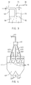
- FIG. 3 shows still another exemplary embodiment of apparatus according to the invention.
- a substantially upright (vertical) de-entrainment vessel 31 substantially circular in cross-section is equipped with a gas and solids transporting pipe 32 which is substantially horizontal where it enters the de-entrainment vessel 31 through a side wall 40, and includes an inlet means 35, provided with a fluidization preventing means 36, at the bottom of a vertical section of pipe 32.
- a gas outlet 34 is also provided.
- the outlet for separated solids is not shown in FIG. 3, however, any suitable arrangement known by a person skilled in the art may be applied.
- the inlet fluidization preventing means 36 is permeable to gas and substantially impermeable to solids.
- the fluidization preventing means 36 preferably has almost no gas permeability (e.g. is essentially solid) at the region thereof nearest the inlet means 35, with gradually increasingly greater gas permeability from the inlet 35 to the side wall 40 of the vessel 31. In this way it is possible to gain the benefits of the present invention substantially without having any enlargement of the discharge opening 35 itself, but merely by having the fluidization preventing means 36 first act as an enlarged flow path of the gas thus causing the reduced velocity and, after the gas permeability of the preventing means 36 is increased, then acting as a gas permeable, solid impermeable, device.
- Gas outlet 34 may be provided with a filtering device (i.e. like device 11 in FIG. 1), and is well above the level of particle bed 38.
- FIG. 4 illustrates still another exemplary embodiment of apparatus according to the present invention which is preferred for the transport of finer solids materials.
- multiple (branch) transporting lines 423, 422, 421 from transporting pipe 42 are adapted to discharge the solids and gaseous material into the interior of the de-entrainment vessel 41, each line 421-423 provided with its own inlet means (e.g. cones) 451, 452, 453.
- a fluidization preventing means 46 e.g. a perforated plate or wire mesh screen, or ceramic filter
- the separated-out gas is subsequently vented out of the de-entrainment vessel 41 through gas outlets 441, 442.
- the number of the inlets 421-423 and outlets 441-442 is dependent upon the process parameters.
- the desired lower gas velocity is accomplished by splitting the initial stream in pipe 42 into a plurality of lines (e.g. 2, 3, or more), while simultaneously maintaining the desired pressure reduction.
- a plurality of solids outlets 43 are also provided, the number depending upon the process parameters and the shape of the vessel 41.
- a splitting means 40 is provided in the transporting pipe 42 above vessel 41.
Landscapes
- Chemical & Material Sciences (AREA)
- Engineering & Computer Science (AREA)
- Chemical Kinetics & Catalysis (AREA)
- Organic Chemistry (AREA)
- Combustion & Propulsion (AREA)
- Mechanical Engineering (AREA)
- General Engineering & Computer Science (AREA)
- Devices And Processes Conducted In The Presence Of Fluids And Solid Particles (AREA)
- Separating Particles In Gases By Inertia (AREA)
- Filtering Of Dispersed Particles In Gases (AREA)
Abstract
Description
EP 392 577 shows an ash discharging vessel connected to a pressurized combustor or gasifier. Ash is introduced into the vessel at intervals, the vessel thereby being pressurized. The vessel is de-pressurized between the ash introduction steps, before discharging ash therefrom. De-pressurizing takes place by venting gas through a de-pressurizing conduit. The de-pressurizing conduit comprises a gas permeable filter element allowing gas only to be discharged therethrough.
Claims (21)
- A method of reducing the pressure of a high pressure solids-gas stream and separating the solids from the solids-gas stream utilizing a de-entrainment vessel including a packed bed of solids formed of solids separated from the solids-gas stream, a solids outlet, a gas outlet above the level of the packed bed connected to a low pressure area, and an inlet for the solids-gas stream into the vessel, said inlet having a discharge opening arranged at or below the level of the bed of packed solids, said method comprising the steps of:(a) introducing the high pressure solids-gas stream into the de-entrainment vessel through the inlet so that the gas of the solids-gas stream flows faster than the solids, to provide a pressure drop of the gas;(b) causing the gas from the solids-gas stream of step (a) to flow through the packed bed of solids;(c) causing the velocity of the gas to decrease during, or just prior to, introduction of the gas into the packed bed of solids, to substantially prevent fluidization of the solids, and to further substantially prevent fluidization of the solids by passing the gas, after or simultaneously with step (b), through an element permeable to gas but substantially impermeable to solids within the gas-solids stream or the packed bed;(d) discharging the gas separated from the solids-gas stream, after it has passed through the packed bed and the element permeable to the gas but substantially impermeable to the solids;(e) discharging solids from the vessel below the level of the packed bed.
- A method as recited in claim 1, wherein the temperature of the solids gas-stream, and bed solids, during the practice of steps (a) - (e) is between about 800 - 1200°C.
- A method as recited in claim 1, wherein the solids-gas stream has a temperature of about 800-1200°C, and comprising the further step of cooling the solids gas-stream so that it has a temperature of about 300 - 799°C prior to step (b).
- A method as recited in claim 1, wherein the solids gas-stream has a pressure of about 2-20 bar, and wherein step (d) is practised to discharge the gas to a substantially atmospheric pressure area.
- A method as recited in claim 1, comprising the further step of dividing the solids-gas stream into a plurality of streams prior to step (b).
- Apparatus for reducing the pressure of a high pressure solids-gas stream and separating the solids from the solids-gas stream, comprising:a substantially vertical de-entrainment vessel (1, 21, 31, 41) having a bed (8, 28, 38, 48) of packed solids separated from the solids-gas stream therein, disposed at a level within said vessel, and a side wall;a transporting pipe (2, 22, 32, 42) containing the solids-gas stream therein at a super-atmospheric pressure;inlet means (5, 25, 35, 451, 452, 453) connected to said transporting pipe, and disposed within said de-entrainment vessel, and including a discharge opening arranged at or below the level of the bed of packed solids;means capable of causing the velocity of the gas to decrease during, or just prior to, introduction of the gas into the packed bed of solids, to substantially prevent fluidisation of the solids;a gas outlet (4, 24, 34, 441, 442) from said vessel located above the level of the bed of solids for the discharge of gas, said outlet being connected to an area having a lower pressure than the pressure in said transporting pipe;a solids outlet (3, 23, 43) from said vessel located below the level of the bed of solids, and connected to an area having a lower pressure than the pressure in said transporting pipe; andmeans (6, 7, 26, 36, 46) for substantially preventing fluidization, comprising a substantially solids impermeable and gas permeable element operatively connected to said inlet means and extending toward said vessel side wall.
- Apparatus as recited in claim 6, wherein said means capable of causing the velocity of the gas to decrease includes a gradually expanding cross-sectional area section at said discharge opening.
- Apparatus as recited in claim 7, wherein said expanding cross-sectional area section comprises a cone (6).
- Apparatus as recited in claim 8, wherein said cone is a right circular cone.
- Apparatus as recited in one of the claims 6 to 9, wherein said fluidization preventing element (26, 36, 46) is directly connected to said inlet means adjacent said discharge opening, and extends from said inlet means toward said vessel wall.
- Apparatus as recited in one of the claims 6 to 10, wherein said fluidization preventing element (36, 46) extends substantially over the entire area between said inlet means and said vessel side wall, substantially defining the upper level of the packed bed of solids.
- Apparatus as recited in one of the claims 6 to 11, wherein said fluidization preventing element (36, 46) is selected from the group consisting essentially of perforated plates, wire mesh screens, and filtering means.
- Apparatus as recited in one of the claims 6 to 12, wherein said fluidization preventing element (36; 46) comprises a ceramic filter.
- Apparatus as recited in one of the claims 6 to 13, wherein said fluidization preventing element (36) has varying gas permeability.
- Apparatus as recited in claim 14, wherein the gas permeability of said fluidization preventing element (36) is lowest closest to said inlet means, and greatest closest to said vessel side wall, and gradually increases from said inlet means toward said vessel side wall.
- Apparatus as recited in claim 8 with the discharge opening of the inlet means arranged below the level of the packed solids bed, further comprising a plurality of openings (7) provided in said cone (6), below the level of the packed solids bed, through which gas flows toward said vessel wall.
- Apparatus as recited in claim 6, wherein said transporting pipe (42) comprises a single transporting pipe having said first cross-sectional area, and wherein said inlet means (451, 452, 453) comprises a plurality of inlet elements connected to and branching from said single transporting pipe, said inlet elements collectively having a second cross-sectional area significantly greater than said first cross-sectional area.
- Apparatus as recited in claim 6, wherein said inlet means (451, 452, 453) comprises a plurality of inlet elements, and wherein said solids outlet (43) comprises a plurality of outlet elements, and wherein said gas outlet (441, 442) comprises a plurality of outlet elements.
- Apparatus as recited in one of the claims 6 to 18 in combination with a pressurized fluidized bed reactor (18) having a pressure of about 2-20 bar, and connected to said transporting pipe.
- Apparatus as recited in claim 19, further comprising cooling means (19) disposed between said reactor and said inlet means for cooling the temperature of the solids-gas stream to about 300-799°C.
- Apparatus as recited in claim 6, further comprising means (40) external of said vessel for splitting the solids-gas stream from said transporting pipe (42) into a plurality of branch pipes (421, 422, 423); and wherein said inlet means comprises an inlet element (451, 452, 453) at an end of each branch pipe opposite said splitting means.
Priority Applications (1)
| Application Number | Priority Date | Filing Date | Title |
|---|---|---|---|
| EP97116537A EP0812613A3 (en) | 1993-04-22 | 1994-04-22 | Method and apparatus for handling high pressure material |
Applications Claiming Priority (2)
| Application Number | Priority Date | Filing Date | Title |
|---|---|---|---|
| US08/051,969 US5567090A (en) | 1993-04-22 | 1993-04-22 | Method and apparatus for separating solids from gas in a high pressure solids-gas stream utilizing a packed bed of the solids |
| US51969 | 1993-04-22 |
Related Child Applications (1)
| Application Number | Title | Priority Date | Filing Date |
|---|---|---|---|
| EP97116537A Division EP0812613A3 (en) | 1993-04-22 | 1994-04-22 | Method and apparatus for handling high pressure material |
Publications (2)
| Publication Number | Publication Date |
|---|---|
| EP0621068A1 EP0621068A1 (en) | 1994-10-26 |
| EP0621068B1 true EP0621068B1 (en) | 1998-07-01 |
Family
ID=21974549
Family Applications (2)
| Application Number | Title | Priority Date | Filing Date |
|---|---|---|---|
| EP94106333A Expired - Lifetime EP0621068B1 (en) | 1993-04-22 | 1994-04-22 | Method and apparatus for reducing the pressure of a high-pressure solids-gas stream |
| EP97116537A Withdrawn EP0812613A3 (en) | 1993-04-22 | 1994-04-22 | Method and apparatus for handling high pressure material |
Family Applications After (1)
| Application Number | Title | Priority Date | Filing Date |
|---|---|---|---|
| EP97116537A Withdrawn EP0812613A3 (en) | 1993-04-22 | 1994-04-22 | Method and apparatus for handling high pressure material |
Country Status (6)
| Country | Link |
|---|---|
| US (2) | US5567090A (en) |
| EP (2) | EP0621068B1 (en) |
| JP (1) | JPH06343810A (en) |
| AT (1) | ATE167812T1 (en) |
| CA (1) | CA2121563C (en) |
| ES (1) | ES2119929T3 (en) |
Families Citing this family (14)
| Publication number | Priority date | Publication date | Assignee | Title |
|---|---|---|---|---|
| NO317050B1 (en) * | 1999-03-01 | 2004-07-26 | Norsk Hydro As | Method and apparatus for filling silo |
| FI106742B (en) * | 1999-06-28 | 2001-03-30 | Foster Wheeler Energia Oy | Method and apparatus for handling particulate pressurized material |
| WO2001035928A1 (en) * | 1999-11-17 | 2001-05-25 | Microchips, Inc. | Microfabricated devices for the delivery of molecules into a carrier fluid |
| JP2004528160A (en) | 2001-03-01 | 2004-09-16 | フィリップス・プラスチックス・コーポレーション | Filtration media for porous inorganic particles |
| US20040139858A1 (en) * | 2001-03-01 | 2004-07-22 | Phillips Plastics Corporation | Filtration media of porous inorganic particles |
| US7041159B2 (en) | 2003-08-04 | 2006-05-09 | Phillips Plastics Corporation | Separation apparatus |
| US6797041B2 (en) * | 2002-03-01 | 2004-09-28 | Greenheck Fan Corporation | Two stage air filter |
| US7166140B2 (en) | 2003-10-22 | 2007-01-23 | Phillips Plastics Corporation | High capture efficiency baffle |
| GB0523338D0 (en) * | 2005-11-16 | 2005-12-28 | Inbulk Technologies Ltd | Vacuum conveying velocity control device |
| GB2474147B (en) * | 2008-07-25 | 2012-05-16 | Hatch Ltd | Apparatus for stabilization and deceleration of supersonic flow incorporating a diverging nozzle and perforated plate |
| US8066789B2 (en) * | 2009-04-20 | 2011-11-29 | Southern Company | Continuous fine ash depressurization system |
| US8684636B2 (en) * | 2011-03-09 | 2014-04-01 | James Dunstan | Air seeder venting system |
| CA2862631C (en) * | 2012-01-27 | 2021-05-04 | Ohio University | Integrated precipatative-super critical technology for cost-effective treatment of flowback and produced water from unconventional gas resources |
| CN110368744A (en) * | 2019-07-16 | 2019-10-25 | 中山市至善生物科技有限公司 | A kind of expanding dedusting temperature-reducing tower and apparatus for thermal cleavage |
Family Cites Families (15)
| Publication number | Priority date | Publication date | Assignee | Title |
|---|---|---|---|---|
| US2684870A (en) * | 1948-12-24 | 1954-07-27 | Union Oil Co | Conveyance of granular solids |
| US2684873A (en) * | 1950-03-13 | 1954-07-27 | Union Oil Co | Method and apparatus for the conveyance of granular solids |
| US2684872A (en) * | 1950-03-13 | 1954-07-27 | Union Oil Co | Conveyance of granular solids |
| US2684868A (en) * | 1951-01-16 | 1954-07-27 | Union Oil Co | Conveyance of granular solids |
| US2901421A (en) * | 1952-07-12 | 1959-08-25 | Socony Mobil Oil Co Inc | Method and apparatus for transfer of contact materials |
| US3146189A (en) * | 1960-12-06 | 1964-08-25 | Shell Oil Co | Distributing vapor-liquid feed to beds |
| FR2374073A1 (en) * | 1976-12-18 | 1978-07-13 | Peters Ag Claudius | MIXING CHAMBER SILO FOR BULK MATERIALS |
| DD141240A3 (en) * | 1977-08-09 | 1980-04-23 | Peter Goehler | HOSPITAL PIPE FOR THE TRANSFER OF DUST-CONTAINING AND DUST-SOUND GUETERS IN A SYSTEM OF HIGHER PRESSURE |
| SE436248B (en) * | 1983-04-15 | 1984-11-26 | Asea Atom Ab | PRESSURE REDUCTION VALVE FOR EXPOSURE OF DUST FROM A PRESSURE CONTAINER EXAMPLE A CYCLON WHICH THE VALVE CONTAINS FLUIDIZABLE PARTICLES |
| FR2548556B1 (en) * | 1983-07-04 | 1985-10-18 | Saint Gobain Vitrage | DEVICE FOR DISPENSING POWDERY PRODUCTS SUSPENDED IN A GAS |
| DE3412930A1 (en) * | 1984-04-06 | 1985-10-17 | L. & C. Steinmüller GmbH, 5270 Gummersbach | METHOD AND DEVICE FOR EJECTING SOLIDS (DUST) FROM PROCESS GASS UNDER PRESSURE |
| FR2607720B1 (en) * | 1986-12-05 | 1990-12-14 | Electricite De France | FILTER ASSEMBLY FOR GASEOUS FLUIDS |
| US4861354A (en) * | 1988-07-29 | 1989-08-29 | Battelle Memorial Institute | Removing pollutant |
| DE3911752C1 (en) * | 1989-04-11 | 1990-06-21 | Metallgesellschaft Ag, 6000 Frankfurt, De | |
| GB9100643D0 (en) * | 1991-01-11 | 1991-02-27 | Shaffery Michael J | Filter system |
-
1993
- 1993-04-22 US US08/051,969 patent/US5567090A/en not_active Expired - Fee Related
-
1994
- 1994-04-18 CA CA002121563A patent/CA2121563C/en not_active Expired - Fee Related
- 1994-04-22 AT AT94106333T patent/ATE167812T1/en not_active IP Right Cessation
- 1994-04-22 JP JP6084880A patent/JPH06343810A/en active Pending
- 1994-04-22 EP EP94106333A patent/EP0621068B1/en not_active Expired - Lifetime
- 1994-04-22 EP EP97116537A patent/EP0812613A3/en not_active Withdrawn
- 1994-04-22 ES ES94106333T patent/ES2119929T3/en not_active Expired - Lifetime
-
1996
- 1996-08-01 US US08/691,912 patent/US5630680A/en not_active Expired - Fee Related
Also Published As
| Publication number | Publication date |
|---|---|
| CA2121563A1 (en) | 1994-10-23 |
| ATE167812T1 (en) | 1998-07-15 |
| CA2121563C (en) | 1999-03-30 |
| US5630680A (en) | 1997-05-20 |
| JPH06343810A (en) | 1994-12-20 |
| ES2119929T3 (en) | 1998-10-16 |
| EP0812613A2 (en) | 1997-12-17 |
| US5567090A (en) | 1996-10-22 |
| EP0621068A1 (en) | 1994-10-26 |
| EP0812613A3 (en) | 1998-02-25 |
Similar Documents
| Publication | Publication Date | Title |
|---|---|---|
| CA2121563C (en) | Method and apparatus for separating solids from gas in high pressure solids-gas stream utilizing a packed bed of the solids | |
| FI119644B (en) | Apparatus and process for polymerization of olefins in gas phase | |
| CA2107543C (en) | Perforated plate fluid distributor and its associated fixed bed vessel | |
| CA2087316C (en) | An apparatus for filtering solid particles from a fluid | |
| US4434726A (en) | Fine particulate feed system for fluidized bed furnace | |
| US4872969A (en) | Method for valveless control of particle transport | |
| JPH1066820A (en) | Radial bed type adsorbing container used in pressure swing or vacuum/pressure swing type gas separation method | |
| HU203683B (en) | Method and apparatus for directing polymerization reactions influidized bed | |
| US4021339A (en) | Water filter | |
| FI110845B (en) | Handling Equipment | |
| US6290775B1 (en) | Fluidized bed reactor and a process of using the same | |
| US4560094A (en) | Particulate solid storage container and transport method | |
| EP1178858B1 (en) | Apparatus and process for removing solid particles from gases | |
| RU2130802C1 (en) | Method and device for treatment of material layer in fluidized-bed reactors | |
| US4446112A (en) | Apparatus for contacting fluid with particulate solid material | |
| AU753423B2 (en) | Separator apparatus | |
| JPS6124048B2 (en) | ||
| US5169607A (en) | Moving-bed reactor, in particular for the treatment of flue gases | |
| US3867116A (en) | Separator | |
| EP0406336A1 (en) | DISTRIBUTION PLATE IN A FLUIDIZED BED REACTOR AND A METHOD FOR STARTING A FLUIDIZED BED REACTOR. | |
| CA2507538A1 (en) | Apparatus for inhibiting fines carryover | |
| US6228328B1 (en) | Standpipe inlet enhancing particulate solids circulation for petrochemical and other processes | |
| JP3278161B2 (en) | Method and apparatus for transporting solid particles from one chamber to another | |
| KR20080080302A (en) | Method and apparatus for regenerating waste FCC catalyst | |
| JP2613737B2 (en) | Structure of high-pressure bubbling cooler and operating method thereof |
Legal Events
| Date | Code | Title | Description |
|---|---|---|---|
| PUAI | Public reference made under article 153(3) epc to a published international application that has entered the european phase |
Free format text: ORIGINAL CODE: 0009012 |
|
| 17P | Request for examination filed |
Effective date: 19940422 |
|
| AK | Designated contracting states |
Kind code of ref document: A1 Designated state(s): AT ES FR |
|
| 17Q | First examination report despatched |
Effective date: 19951218 |
|
| RAP1 | Party data changed (applicant data changed or rights of an application transferred) |
Owner name: FOSTER WHEELER ENERGIA OY |
|
| GRAG | Despatch of communication of intention to grant |
Free format text: ORIGINAL CODE: EPIDOS AGRA |
|
| GRAG | Despatch of communication of intention to grant |
Free format text: ORIGINAL CODE: EPIDOS AGRA |
|
| GRAG | Despatch of communication of intention to grant |
Free format text: ORIGINAL CODE: EPIDOS AGRA |
|
| GRAH | Despatch of communication of intention to grant a patent |
Free format text: ORIGINAL CODE: EPIDOS IGRA |
|
| GRAH | Despatch of communication of intention to grant a patent |
Free format text: ORIGINAL CODE: EPIDOS IGRA |
|
| RIN1 | Information on inventor provided before grant (corrected) |
Inventor name: SELLAKUMAR, KURUKKAMPALAYAM M. Inventor name: BASAK, ARUN K. |
|
| GRAA | (expected) grant |
Free format text: ORIGINAL CODE: 0009210 |
|
| AK | Designated contracting states |
Kind code of ref document: B1 Designated state(s): AT ES FR |
|
| REF | Corresponds to: |
Ref document number: 167812 Country of ref document: AT Date of ref document: 19980715 Kind code of ref document: T |
|
| XX | Miscellaneous (additional remarks) |
Free format text: TEILANMELDUNG 97116537.8 EINGEREICHT AM 23/09/97. |
|
| REG | Reference to a national code |
Ref country code: ES Ref legal event code: FG2A Ref document number: 2119929 Country of ref document: ES Kind code of ref document: T3 |
|
| ET | Fr: translation filed | ||
| PLBE | No opposition filed within time limit |
Free format text: ORIGINAL CODE: 0009261 |
|
| STAA | Information on the status of an ep patent application or granted ep patent |
Free format text: STATUS: NO OPPOSITION FILED WITHIN TIME LIMIT |
|
| 26N | No opposition filed | ||
| PGFP | Annual fee paid to national office [announced via postgrant information from national office to epo] |
Ref country code: AT Payment date: 20020307 Year of fee payment: 9 |
|
| PGFP | Annual fee paid to national office [announced via postgrant information from national office to epo] |
Ref country code: FR Payment date: 20020311 Year of fee payment: 9 |
|
| PGFP | Annual fee paid to national office [announced via postgrant information from national office to epo] |
Ref country code: ES Payment date: 20020408 Year of fee payment: 9 |
|
| PG25 | Lapsed in a contracting state [announced via postgrant information from national office to epo] |
Ref country code: AT Free format text: LAPSE BECAUSE OF NON-PAYMENT OF DUE FEES Effective date: 20030422 |
|
| PG25 | Lapsed in a contracting state [announced via postgrant information from national office to epo] |
Ref country code: ES Free format text: LAPSE BECAUSE OF NON-PAYMENT OF DUE FEES Effective date: 20030423 |
|
| PG25 | Lapsed in a contracting state [announced via postgrant information from national office to epo] |
Ref country code: FR Free format text: LAPSE BECAUSE OF NON-PAYMENT OF DUE FEES Effective date: 20031231 |
|
| REG | Reference to a national code |
Ref country code: FR Ref legal event code: ST |
|
| REG | Reference to a national code |
Ref country code: ES Ref legal event code: FD2A Effective date: 20030423 |