EP0620906B1 - Low emission combustion system for a gas turbine engine - Google Patents
Low emission combustion system for a gas turbine engine Download PDFInfo
- Publication number
- EP0620906B1 EP0620906B1 EP92925013A EP92925013A EP0620906B1 EP 0620906 B1 EP0620906 B1 EP 0620906B1 EP 92925013 A EP92925013 A EP 92925013A EP 92925013 A EP92925013 A EP 92925013A EP 0620906 B1 EP0620906 B1 EP 0620906B1
- Authority
- EP
- European Patent Office
- Prior art keywords
- gas turbine
- combustor
- turbine engine
- air
- injection nozzle
- Prior art date
- Legal status (The legal status is an assumption and is not a legal conclusion. Google has not performed a legal analysis and makes no representation as to the accuracy of the status listed.)
- Expired - Lifetime
Links
- 238000002485 combustion reaction Methods 0.000 title abstract description 19
- 239000000446 fuel Substances 0.000 claims abstract description 93
- 238000002347 injection Methods 0.000 claims abstract description 38
- 239000007924 injection Substances 0.000 claims abstract description 38
- 230000007246 mechanism Effects 0.000 claims abstract description 31
- 230000015572 biosynthetic process Effects 0.000 claims abstract description 9
- 238000001816 cooling Methods 0.000 claims description 6
- 230000001419 dependent effect Effects 0.000 claims 1
- 239000007789 gas Substances 0.000 abstract description 50
- MWUXSHHQAYIFBG-UHFFFAOYSA-N nitrogen oxide Inorganic materials O=[N] MWUXSHHQAYIFBG-UHFFFAOYSA-N 0.000 description 40
- GQPLMRYTRLFLPF-UHFFFAOYSA-N Nitrous Oxide Chemical compound [O-][N+]#N GQPLMRYTRLFLPF-UHFFFAOYSA-N 0.000 description 17
- 238000004891 communication Methods 0.000 description 10
- 239000012530 fluid Substances 0.000 description 10
- XLYOFNOQVPJJNP-UHFFFAOYSA-N water Chemical compound O XLYOFNOQVPJJNP-UHFFFAOYSA-N 0.000 description 10
- UGFAIRIUMAVXCW-UHFFFAOYSA-N Carbon monoxide Chemical compound [O+]#[C-] UGFAIRIUMAVXCW-UHFFFAOYSA-N 0.000 description 9
- 229910002091 carbon monoxide Inorganic materials 0.000 description 9
- 229930195733 hydrocarbon Natural products 0.000 description 9
- 150000002430 hydrocarbons Chemical class 0.000 description 9
- IJGRMHOSHXDMSA-UHFFFAOYSA-N Atomic nitrogen Chemical compound N#N IJGRMHOSHXDMSA-UHFFFAOYSA-N 0.000 description 8
- 239000004215 Carbon black (E152) Substances 0.000 description 7
- 239000007788 liquid Substances 0.000 description 6
- 238000012544 monitoring process Methods 0.000 description 5
- CURLTUGMZLYLDI-UHFFFAOYSA-N Carbon dioxide Chemical compound O=C=O CURLTUGMZLYLDI-UHFFFAOYSA-N 0.000 description 4
- 230000009977 dual effect Effects 0.000 description 4
- 238000002156 mixing Methods 0.000 description 4
- 229910052757 nitrogen Inorganic materials 0.000 description 4
- 238000007789 sealing Methods 0.000 description 4
- 238000013461 design Methods 0.000 description 3
- 238000000034 method Methods 0.000 description 3
- 230000009467 reduction Effects 0.000 description 3
- 230000004913 activation Effects 0.000 description 2
- 229910002092 carbon dioxide Inorganic materials 0.000 description 2
- 239000001569 carbon dioxide Substances 0.000 description 2
- 230000008859 change Effects 0.000 description 2
- 238000012986 modification Methods 0.000 description 2
- 230000004048 modification Effects 0.000 description 2
- 239000000779 smoke Substances 0.000 description 2
- XTQHKBHJIVJGKJ-UHFFFAOYSA-N sulfur monoxide Chemical class S=O XTQHKBHJIVJGKJ-UHFFFAOYSA-N 0.000 description 2
- 229910052815 sulfur oxide Inorganic materials 0.000 description 2
- NINIDFKCEFEMDL-UHFFFAOYSA-N Sulfur Chemical compound [S] NINIDFKCEFEMDL-UHFFFAOYSA-N 0.000 description 1
- WYTGDNHDOZPMIW-RCBQFDQVSA-N alstonine Natural products C1=CC2=C3C=CC=CC3=NC2=C2N1C[C@H]1[C@H](C)OC=C(C(=O)OC)[C@H]1C2 WYTGDNHDOZPMIW-RCBQFDQVSA-N 0.000 description 1
- 230000000712 assembly Effects 0.000 description 1
- 238000000429 assembly Methods 0.000 description 1
- QVGXLLKOCUKJST-UHFFFAOYSA-N atomic oxygen Chemical compound [O] QVGXLLKOCUKJST-UHFFFAOYSA-N 0.000 description 1
- 230000000740 bleeding effect Effects 0.000 description 1
- 238000007599 discharging Methods 0.000 description 1
- 239000003344 environmental pollutant Substances 0.000 description 1
- 239000002803 fossil fuel Substances 0.000 description 1
- 238000004519 manufacturing process Methods 0.000 description 1
- 239000000203 mixture Substances 0.000 description 1
- 239000001272 nitrous oxide Substances 0.000 description 1
- 125000001477 organic nitrogen group Chemical group 0.000 description 1
- 239000001301 oxygen Substances 0.000 description 1
- 229910052760 oxygen Inorganic materials 0.000 description 1
- 231100000719 pollutant Toxicity 0.000 description 1
- 239000000047 product Substances 0.000 description 1
- 230000003134 recirculating effect Effects 0.000 description 1
- 239000007921 spray Substances 0.000 description 1
- 229910052717 sulfur Inorganic materials 0.000 description 1
- 239000011593 sulfur Substances 0.000 description 1
- 238000009834 vaporization Methods 0.000 description 1
- 230000008016 vaporization Effects 0.000 description 1
Images

Classifications
-
- F—MECHANICAL ENGINEERING; LIGHTING; HEATING; WEAPONS; BLASTING
- F23—COMBUSTION APPARATUS; COMBUSTION PROCESSES
- F23R—GENERATING COMBUSTION PRODUCTS OF HIGH PRESSURE OR HIGH VELOCITY, e.g. GAS-TURBINE COMBUSTION CHAMBERS
- F23R3/00—Continuous combustion chambers using liquid or gaseous fuel
- F23R3/02—Continuous combustion chambers using liquid or gaseous fuel characterised by the air-flow or gas-flow configuration
- F23R3/26—Controlling the air flow
-
- F—MECHANICAL ENGINEERING; LIGHTING; HEATING; WEAPONS; BLASTING
- F05—INDEXING SCHEMES RELATING TO ENGINES OR PUMPS IN VARIOUS SUBCLASSES OF CLASSES F01-F04
- F05D—INDEXING SCHEME FOR ASPECTS RELATING TO NON-POSITIVE-DISPLACEMENT MACHINES OR ENGINES, GAS-TURBINES OR JET-PROPULSION PLANTS
- F05D2270/00—Control
- F05D2270/01—Purpose of the control system
- F05D2270/08—Purpose of the control system to produce clean exhaust gases
- F05D2270/082—Purpose of the control system to produce clean exhaust gases with as little NOx as possible
Definitions
- the present invention relates to a system for automatically maintaining gas turbine nitrogen oxide (NOx) emissions at a specific level in parts per million by volume during all ambient conditions for no load to full load operating parameters. More particularly, the invention relates to a system for controlling the combustible air directed to the injection nozzle to be mixed with the fuel to control the air to fuel ratio.
- NOx gas turbine nitrogen oxide
- Past and some present systems suggested means for reducing the maximum temperature in the combustion zone of a gas turbine combustor have included schemes for introducing more air at the combustion zone, recirculating cooled exhaust products into the combustion zone and injecting water spray into the combustion zone.
- An example of such a system is disclosed in US-A-4,733,527.
- the method and apparatus disclosed therein automatically maintains the NOx emissions at a substantially constant level during all ambient conditions and for no load to full load fuel flows.
- the water/fuel ratio is calculated for a substantially constant level of NOx emissions at the given operating conditions and, knowing the actual fuel flow to the gas turbine, a signal is generated representing the water metering valve position necessary to inject the proper water flow into the combustor to achieve the desired water/fuel ratio.
- the apparatus has a combination of serpentine geometried, fuel-mixing tubes discharging to the radially outward area of the combustor and an axially oriented, fuel-mixing tube near the center of the combustor adapted to generate a strong centrifugal force field within the combustor.
- the tube near the center has a convergent section and a divergent section.
- a fuel supply means discharges fuel into the convergent section wherein vaporization is maintained by an axial velocity over the length of the tube.
- the force field promotes rapid mixing and combustion within the chamber to reduce both the magnitude of the combustor temperature and the period of exposure of the medium gases to that temperature, thus reducing the formation of NOx.
- the US-A-4 733 527 concept requires an additional means for injecting water into the combustion chamber which includes a water source, a control valve, a controlling and monitoring system and a device for injecting water into the combustion chamber.
- the US-A-4 215 535 concept requires a plurality of fuel-mixing tubes or injectors, a control system for each tube and a monitoring system with feedback to each of the controls of the individual tubes.
- the US-A-3842597 concept requires additional components to bleed and cool a portion of the airflow pressured by the compressor and hardware for reintroducing the cooled air into the combustor.
- US-A-4562698 discloses a control system for reducing the formation of exhaust emissions during operation of a gas turbine engine, the engine including a source of compressed air, a combustor and a turbine arranged in serial order and at least one fuel injection nozzle for directing a combustible fuel and compressed air into the combustor;
- the control system comprises means for directing a portion of the flow of compressed air exiting the compressor section through the injection nozzle into the combustor in an amount sufficient, with the addition of an appropriate amount of fuel, to support full fuel operation of the gas turbine engine at rated speed; and means for controllably varying the amount of air directed into the combustor by directing a portion of the air from the compressor section into the injection nozzle when the engine is operated at power levels between low fuel and high fuel conditions, the means for controllably varying being operatively positioned between the source of compressed air and the fuel injection nozzle and, according to a first aspect of the present invention, such a control system is characterised by the means including
- a gas turbine engine has a control system for reducing the formation of exhaust emissions during operation of a gas turbine engine, the engine including a source of compressed air, a combustor and a turbine arranged in serial order and at least one fuel injection nozzle directing a combustible fuel and compressed air into the combustor; the control system comprising means for directing air from the source of compressed air through the injection nozzle into the combustor in an amount sufficient, with the addition of an appropriate amount of fuel, to support full fuel operation of the gas turbine engine at rated speed; and means for controllably varying the amount of air directed into the combustor by directing a portion of the air from the compressor section into the injection nozzle when the engine is operated at power levels between low fuel and high fuel conditions, the means for controllably varying being operatively positioned between the source of compressed air and the combustor characterised by the means including a pre-established flow area formed between an outer housing and an inner case, less the area of the
- a gas turbine engine 10 having a control system 12 for reducing nitrous oxide emissions therefrom is shown.
- the gas turbine engine 10 has an outer housing 14 having therein a plurality of openings 16, of which only one is shown, having a preestablished position and relationship one to another.
- a plurality of threaded holes 18 are positioned relative to the plurality of openings 16.
- the housing 14 further includes at least a single aperture 19 therein and a central axis 20.
- the housing 14 is positioned about a compressor section 22 centered about the axis 20, a turbine section 24 centered about the axis 20 and a combustor section 26 positioned operatively between the compressor section 22 and the turbine section 24.
- the engine 10 has an inner case 28 coaxially aligned about the axis 20 and is disposed radially inwardly of the compressor section 22, turbine section 24 and the combustor section 26.
- the turbine section 24 includes a power turbine 30 having an output shaft, not shown, connected thereto for driving an accessory component such as a generator.
- Another portion of the turbine section 24 includes a gas producer turbine 32 connected in driving relationship to the compressor section 22.
- the compressor section 22, in this application, includes an axial staged compressor 34 having a plurality of rows of rotor assemblies 36, of which only one is shown. When the engine 10 is operating, the compressor 34 causes a flow of compressed air exiting therefrom designated by the arrows 38.
- the compressor section 22 could include a radial compressor or any source for producing compressed air.
- the combustor section 26 includes an annular combustor 40 being radially spaced a preestablished distance from the outer housing 14 and the inner case 28.
- the combustor 40 is supported from the inner case 28 in a conventional manner.
- the combustor 40 has a generally cylindrical outer shell 50 being coaxially positioned about the central axis 20, a generally cylindrical inner shell 52 having an outer surface 53 being coaxial with the outer shell 50, an inlet end 54 having a plurality of generally evenly spaced openings 56 therein and an outlet end 58.
- the combustor 40 is constructed of a plurality of generally conical segments 60.
- the outer shell 50 has an outer surface 62 and an inner surface 64 extending generally between the inlet end 54 and the outlet end 58.
- Each of the openings 56 has an injector 66 having a central axis 68 positioned therein, in the inlet end 54 of the combustor 40.
- the area between the outer housing 14 and the inner case 28 less the area of the combustor section 26 forms a preestablished flow or cooling area 70 through which the major portion of the compressed air 38 will flow. In this application, approximately 50 to 70 percent of the compressed air 38 is used for cooling.
- a plurality of can type combustors could be incorporated without changing the gist of the invention.
- each of the injectors 66 are of the single gaseous fuel type.
- Each of the injectors 66 is supported from the housing 14 in a conventional manner.
- an outer tubular member 72 has a passage 74 therein.
- the tubular member 72 includes an inlet end portion 76 and an outlet end portion 78.
- the tubular member 72 extends radially through one of the plurality of openings 16 in the outer housing 14 and has a mounting flange 80 extending therefrom.
- the flange 80 has a plurality of holes 82 therein in which a plurality of bolts 84 threadedly attach to the threaded holes 18 in the outer housing 14.
- the injector 66 is removably attached to the outer housing 14.
- the injector 66 includes a generally cylindrical outer casing 86 having a wall 88 defining an inner surface 90 and an outer surface 92.
- the casing 86 is coaxially positioned about the central axis 68 and has a first end 94 closed by a plate 96 and a second open end 98.
- An aperture 100 defined in the wall 88 has the tubular member 72 fixedly attached therein.
- the aperture 100 is defined near the first end 94 and extends between the outer surface 92 and the inner surface 90.
- a plurality of swirlers 102 each have a preestablished length and shape, an outer portion 104 generally evenly positioned about the inner surface 90 of the casing 86 intermediate the aperture 100 and the second end 98 is attached to the inner surface 90.
- the inner member 108 includes an end cap 110 and a main body 112 having a first end 114, a second end 116 and an external stepped surface 118 extending between the ends 114,116.
- the end cap 110 includes a first end 120, a second end 122 and a concave inner surface 124 extending from the first end 120 toward the second end 122.
- the first end 120 of the end cap 110 is attached to the main body 112 at the second end 116.
- the inner member 108 further includes a generally cylindrical shell 126 coaxially positioned about the central axis 68 and having a first end 128 and a second end 129.
- the first end 128 is attached to the external surface 118 intermediate the first and second ends 114,116 of the main body 112.
- the first end 114 of the main body 112 is also attached to the plate 96 or as an alternative may be integrally formed therewith.
- a first chamber 130 is defined by the end plate 96, a portion of the inner surface 90 of the casing 86, the plurality of swirlers 102 and a portion of the external surface 118 of the main body 112.
- a plurality of holes or passages 131 in the plate 96 communicate with the first chamber 130 and have a combined predetermined total area.
- the predetermined total area of the plurality of holes 131 is equal to approximately 50 to 70 percent of the total maximum flow of compressed air passing through the injector nozzle 66.
- a second chamber or main air passage 132 is defined by the plurality of swirlers 102, a portion of the inner surface 90 of the casing 86, a portion of the shell 126 and the second open end 98 of the casing 86 and the second end 129 of the shell 126.
- a first gaseous fuel gallery or annular groove 134 is defined intermediate the first and second ends 114,116 of the main body 112 and extends inwardly from the external surface 118 of the main body 112 a preestablished distance.
- a portion of the shell 126 is positioned over a portion of the external stepped surface 118 in sealing relationship and further defines the first annular groove 134.
- a main gas passage 136 communicates between the first annular groove 134 and the external surface 118 and exits near the first end 114 of the main body 112.
- a first gas tube 138 is at least partially positioned within the passage 74 of the tubular member 72 and has a first end portion 140 fixedly attached within the main gas passage 136 near the exit thereof at the external surface 118.
- a second end 142 of the first gas tube 138 sealingly exits the passage 74 through the wall of the tubular member 72 and has a threaded fitting 144 attached thereto for communicating with a source of gaseous combustible fuel, not shown.
- a plurality of holes 148 are radially spaced about the shell 126 and communicate between the first annular groove 134 and the second chamber 132.
- a hollow cylindrical spoke member 150 Positioned in each of the plurality of holes 148 is a hollow cylindrical spoke member 150 having a preestablished length, a first end 152 which is closed and a second end 154 which is open.
- the second end 154 of the spoke members 150 is positioned in each of the plurality of holes 148 and the spoke member 150 extends radially outward from the shell 126.
- the spoke member 150 has a plurality of passages 156 therein which are axially spaced along the cylinder.
- the plurality of passages 156 are positioned in such a manner so as to inject gaseous fuel in a predetermined manner into the second chamber 132 and the first closed end 152 is positioned radially inwardly from the inner surface 90 of the casing 86.
- the plurality of passages 156 are in fluid communication with the hollow portion of the cylindrical spoke member 150, the first annular groove 134 and the main gas passage 136.
- a means 160 for passing the main source of fuel through the injector 66 is formed.
- the means 160 for passing the main source of fuel includes the main air passage 132, the plurality of spoke members 150, the first annular groove 134, the main gas passage 136 , the first gas tube 138 and the source of gaseous combustible fuel.
- a pilot chamber 164 is defined by the concave surface 124 within the internal configuration of the end cap 110 of the inner member 108.
- the second end 122 of the end cap 110 has a plurality of exit passages 168, radially spaced thereabout, defined therein and in fluid communication with the pilot chamber 164.
- Each of the plurality of exit passages 168 is at an oblique angle to the central axis 68 of the injector nozzle 66.
- a pilot gas passage 170 communicates between the pilot chamber 164 and the external surface 118 of the main body 112 near the first end 114 of the main body 112.
- a second gas tube 172 is at least partially positioned within the passage 74 of the tubular member 72 and has a first end 174 fixedly attached within the pilot gas passage 170 near the exit thereof at the external surface 116.
- a second end 176 of the second gas tube 172 sealingly exits the passage 74 through the wall of the tubular member 72 and has a threaded fitting 178 attached thereto for communicating with a source of gaseous combustible fuel, not shown.
- the source of gaseous combustible fuels may be the same or an alternate sources from that supplied to the main gas passage 136.
- a set of swirlers 180 each having a preestablished length and shape are generally evenly spaced and positioned inwardly about the shell 126 and outwardly from the end cap 110.
- the set of swirlers 180 are spaced a preestablished distance from a portion of the external stepped surface 118 and define a second fuel gallery or annular groove 182 between a portion of the external stepped surface 118, the shell 126 and the set of swirlers 180.
- a secondary passage 184 communicates between the second annular groove 182, the first end 114 of the main body 112 and further passes through the plate 96.
- the injector nozzle 66 further includes a means 186 for introducing secondary air into the injector nozzle 66.
- the means for introducing secondary air into the injector nozzle 66 includes the secondary passage 184 and the plurality of holes 131 in the plate 96.
- a dual fuel type injector 190 gaseous and liquid, can be used in place of the single gaseous fuel injector 66.
- the nomenclature used to identify the dual fuel type injector 190 is identical to that used to identify the single gaseous fuel type injector 66; however, the numbers are different.
- Each of the injectors 190 has a central axis 192 and is supported from the outer housing 14 in a conventional manner.
- an outer tubular member 272 has a passage 274 therein.
- the tubular member 272 includes an inlet end portion 276 and an outlet end portion 278.
- the tubular member 272 extends radially through one of the plurality of openings 16 in the outer housing 14 and has a mounting flange 280 extending therefrom.
- the flange 280 has a plurality of hole 282 therein in which a plurality of bolts, not shown, threadedly attach to the threaded holes 18 in the outer housing 14.
- the injector 190 is removably attached to the outer housing 14.
- the injector 190 includes a generally cylindrical outer casing 286 having a wall 288 defining an inner surface 290 and an outer surface 292.
- the casing 286 is coaxially positioned about the central axis 192 and has a first end 294 which is closed by a plate 296 and a second open end 298.
- An aperture 300 defined in the wall 288 has the tubular member 272 fixedly attached therein.
- the aperture 300 is defined near the first end 294 and extends between the outer surface 292 and the inner surface 290.
- a plurality of swirlers 302 each have a preestablished length and shape, an outer portion 304 generally evenly spaced about the inner surface 290 of the casing 286 intermediate the aperture 300 and the second end 298 is attached to the inner surface 290.
- An inner portion 306 of each of the plurality of swirlers 302 is attached to an inner member 308 which is coaxially positioned about the central axis 192.
- the inner member 308 includes an end cap 310 and a main body 312 having a first end 314, a second end 316 and an external stepped surface 318.
- the end cap 310 includes a first end 320, a second end 322 and a concave inner surface 324 extending from the first end 320 toward the second end 322.
- the first end 320 of the end cap 310 is attached to the main body 312 near the second end 316.
- the inner member 308 further includes a generally cylindrical shell 326 which is coaxially positioned about the central axis 192 and has a first end 328 and a second end 329.
- the first end 328 is attached to the external surface 318 intermediate the first and second ends 314,316 of the main body 312.
- the first end 314 of the main body 312 is also attached to the plate 296 or as an alternative may be integrally formed therewith.
- a first chamber 330 is defined by the end plate 296, a portion of the inner surface 290 of the casing 286, the plurality of swirlers 302 and a portion of the external surface 318 of the main body 312.
- a plurality of holes or passages 331 in the plate 296 communicate with the first chamber 330 and have a combined predetermined total area.
- the predetermined total area of the plurality of holes 331 is equal to approximately 50 to 75 percent of the total maximum flow of compressed air passing through the injector nozzle 190.
- a second chamber or main air passage 332 is defined by the plurality of swirlers 302, a portion of the inner surface 290 of the casing 286, a portion of the shell 326, the second open end 298 of the casing 286 and the second end 329 of the shell 326.
- a main gaseous fuel gallery or first annular groove 334 is defined intermediate the first and second ends 314,316 and extends inwardly from the external surface 318 of the main body 312 a preestablished distance.
- a portion of the shell 326 is positioned over a portion of the external stepped surface 318 in sealing relationship and further defines the first annular groove 334.
- a main gas passage 336 communicates between the first annular groove 334 and exits the external surface 318 near the first end 314 of the main body 312.
- a first gas tube 338 is at least partially positioned within the passage 274 of the tubular member 272 and has a first end portion 340 fixedly attached within the main gas passage 336 near the exit thereof at the external surface 318.
- a second end 342 of the first gas tube 338 sealingly exits the passage 274 through the wall of the tubular member 272 and has a threaded fitting 344 attached thereto for communicating with a source of gaseous combustible fuel, not shown.
- a plurality of holes 348 are defined within the shell 326, radially spaced about the shell 326 and communicate between the first annular groove 334 and the second chamber 332.
- a hollow cylindrical spoke member 350 Positioned in each of the plurality of holes 348 is a hollow cylindrical spoke member 350 having a preestablished length, a first end 352 which is closed and a second end 354 which is open.
- the second end 354 of the spoke member 350 is positioned in each of the plurality of holes 348 and the spoke member 350 extends radially outward from the shell 326.
- the spoke member 350 has a plurality of passages 356 therein which are axially spaced along the cylinder.
- the plurality of passages 356 are in fluid communication with the hollow portion of the cylindrical spoke member 350, the first annular ring 334 and the main gas passage 336.
- the plurality of passages 356 are positioned in such a manner so as to inject gaseous fuel in a predetermined manner into the second chamber 332 and the first closed end 352 is positioned radially inwardly from the inner surface 290 of the casing 286.
- a pilot chamber 364 is defined by the concave surface 324 within the internal configuration of the end cap 310 of the inner member 308.
- the second end 322 of the end cap 310 has a plurality of exit passages 368 radially spaced thereabout, defined therein and in fluid communication with the pilot chamber 364.
- Each of the plurality of exit passages 368 is at an oblique angle to the central axis 192 of the injector nozzle 190.
- a pilot gas passage 370 communicates between the pilot chamber 364 and the external surface 318 of the main body 312 near the first end 314 of the main body 312.
- a second gas tube 372 is at least partially positioned within the passage 274 of the tubular member 272 and has a first end 374 fixedly attached within the pilot gas passage 370 near the exit thereof at the external surface 316.
- a second end 376 of the second gas tube 372 sealingly exits the passage 274 through the wall of the tubular member 272 and has a threaded fitting 378 attached thereto for communicating with a source of gaseous combustible fuel, not shown.
- the source of gaseous combustible fuels may be the same as the source supplied to the main gas passage 336 or an alternate sources.
- a set of swirlers 380 each having a preestablished length and shape are generally evenly spaced and positioned inwardly about the shell 326 and outwardly from the end cap 310.
- the set of swirlers 380 are spaced a preestablished distance from a portion of the external stepped surface 318 and define a second annular groove 382 between the external stepped surface 318, the shell 326 and the set of swirlers 380.
- a secondary passage 384 communicates between the second annular groove 382, the first end 314 of the main body 312 and further passes through the plate 296.
- the injector nozzle 190 further includes a means 385 for introducing secondary air into the injector nozzle 190.
- the means 385 for introducing secondary air into the injector nozzle 190 includes the secondary passage 384 and the plurality of holes 331 in the plate 296.
- a third fuel gallery or annular groove 390 is defined intermediate the first annular groove 334 and the second annular groove 382.
- the third annular groove 390 extends inwardly from the external surface 318 of the main body 312 a preestablished distance.
- a portion of the shell 326 is positioned over a portion of the external stepped surface 318 in sealing relationship and further defines the third annular groove 390.
- a liquid fuel passage 392 communicates between the third annular groove 390 and the external surface 318 and exits near the first end 314 of the main body 312.
- a liquid fuel tube 394 is at least partially positioned within the passage 274 of the tubular member 272 and has a first end portion 396 fixedly attached within the liquid fuel passage 392 near the exit thereof at the external surface 318.
- a second end 398 of the liquid fuel tube 394 sealingly exits the passage 274 through the wall of the tubular member 272 and has a threaded fitting 400 attached thereto for communicating with a source of liquid combustible fuel, not shown.
- a plurality of holes 402 are axially spaced between the plurality of holes 348 and the second end 329 of the shell 326. The plurality of holes 402 are generally evenly, circumferentially and radially spaced about the shell 326 and communicate between the third annular groove 390 and the second chamber 232.
- This injection nozzle 430 includes an outer tubular member 432 having a passage 434 therein.
- the tubular member 432 extends radially through one of the plurality of openings 16 in the housing 14 and has a mounting flange, not shown extending therefrom.
- the flange has a plurality of holes therein to receive a plurality of bolts for threadedly attaching within the threaded holes 16 in the housing 14.
- the tubular member 432 further includes an inlet end portion 436 and an outlet end portion 438.
- the nozzle 430 further includes a generally cylindrical casing 440 having a wall 442 defining an inner surface 444 and an outer surface 446, a shell 448 defining an inner surface 450 and an outer surface 452, a first end portion 454 and a second end portion 458.
- a channel shaped member 460 includes an inlet portion 462 extending from a base 464. The inlet portion 462 is attached to the shell 448 of the casing 440 near the second end portion 458 and has an aperture 466 defined therein. The inlet portion 462 defines a means 467 for introducing secondary air into the injector nozzle 430.
- the means for introducing secondary air is an orifice or passage 468 positioned in the base 464, defined by the inlet portion 462 and centered about the axis of the injector nozzle 430.
- the orifice 468 has a preestablished area.
- the inlet portion 462 is positioned in spaced relationship to the inner surface 444 of the inner wall 442 of the casing 440 and forms an orifice or passage 470 therebetween having a preestablished area.
- the orifice 470 is formed between the casing 440 and the inlet portion 462.
- the inlet end portion 436 of the outer tube member 432 is coaxially aligned with the aperture 466 and is fixedly attached to the channel member 460.
- the tube passage 434 is in fluid communication with the orifice 470.
- a plurality of swirler vanes 472 having a preestablished length and shape are generally evenly spaced about the inner surface 444 of the inner wall 442 and have one end fixedly attached thereto.
- a deflector member 474 is radially, inwardly, coaxially positioned within the casing 440 and is fixedly attached to the other end of each of the plurality of swirler vanes 472.
- a fourth fuel gallery or annular ring 478 is formed externally of the casing 440.
- the fourth annular ring 478 is defined by the outer surface 446 of the inner wall 442, a plate 480 positioned at the inlet end portion 458, the inner surface 450 of the outer wall 448 and a plate 481 positioned at the outlet end portion 454.
- a plurality of holes 482 Positioned in the inner wall 442 of the casing 440 intermediate the end 454,458 is a plurality of holes 482 extending radially between the inner surface 444 and the outer surface 446. Positioned in each of the plurality of holes 482 and extending radially inwardly from the inner surface 444 of the inner wall 442 is a plurality of hollow spoke members 484. Each of the spoke members 484 have a preestablished length, a first end 486 which is closed and a second end 488 which is open. The second end 488 is positioned in each of the plurality of holes 482. A plurality of passages 490 are axially spaced along each of the spoke members 484 and are in fluid communication with the hollow portion of each of the spoke members 484.
- the injection nozzle 430 further includes a means 492 for communicating between the source of fuel and the main fuel gallery 478.
- the means 492 for communicating includes a tube 494 being in fluid communication between the main fuel gallery 478 and the source of fuel.
- One end of the tube 494 is attached to the fourth annular ring 478 and the other end of the tube 494 sealing exits the housing 14 for communicating with a source of fuel.
- the injection nozzle 430 further includes an air passage 500 having a preestablished total area.
- the passage 500 is formed radially inwardly of the inner surface 444 of the inner wall 442 of the main body 440 and extends axially intermediate the inlet end portion 458 and the outlet end portion 454.
- the deflector member 474 is positioned within the air passage 500 and restricts the amount of compressed air flowing therethrough and forms a second chamber or main air passage 502 having a preestablished area.
- the main air passage 502 is positioned between the inner surface 444 and the deflector member 474. In this application, approximately 50 to 75 percent of the total maximum flow of compressed air passing through the injector nozzle 430 enters into the preestablished area of the air passage 500.
- the flow of compressed air through the main air passage 502 into the combustor 40 is an amount sufficient, with the addition of an appropriate amount of fuel, to support full load operation of the gas turbine engine 10.
- the plurality of passages 490 are positioned in such a manner so as to inject fuel in a predetermined manner into the main air passage 502 and the first closed end 486 is positioned radially inwardly from the inner surface 444 of the inner wall 442.
- the preestablished effective cross sectional area of the orifice 470 which is in fluid communication with the air passage 500, is equal to approximately 50 to 75 percent of the effective cross sectional area of the preestablished area between the main body 440 and the deflector member 474.
- the control system 12 for reducing nitrogen oxide, carbon monoxide and unburned hydrocarbon emissions from the gas turbine engine 10 includes a means 560 for directing a portion of the flow of compressed air exiting the compressor section 22 through the injection nozzles 66,190,430 into the inlet end 48 of the combustor 40.
- the means 560 for directing a portion of the flow of compressed air includes the outer housing 14 and the inner case 28 and the outer shell 44, the inlet end 48 and the inner shell 46 of the combustor section 26.
- the preestablished spaced relationship of the outer and inner shells 44,46 of the combustor 40 to the outer housing 14 and the inner case 28 which forms the preestablished flow area 70 between the combustor 40, and the outer housing 14 and the inner case 26 is also a part of the means 560 for directing.
- the control system 12 for reducing nitrogen oxide, carbon monoxide and unburned hydrocarbon emissions from the engine 10 further includes a manifold 562 having a passage 564 therein.
- the manifold 562 is positioned externally of and encircles the outer housing 14.
- a plurality of openings 566 in the manifold correspond in location to the location of each of the tubular members 72,272,432.
- the tubular members 72,272,432 form a part of a means 568 for ducting and are attached in fluid communication with the plurality of openings 566 in the manifold 562.
- the tube passage 74,274,434 of the tubular member 72,272,432 is in fluid communication with the compressed air inside the passage 564 within the manifold 562.
- the means 568 for ducting includes a plurality of elbows, flanges and connectors 570.
- the manifold 562 further includes at least one primary inlet opening 572 having a duct 574 attached thereto.
- the duct 574 has a passage 576 defined therein which is in,communicates with the passage 564 within the manifold 562 and the preestablished flow areas 70 between the combustor 40, and the outer housing 14 and the inner case 26 by way of the aperture 19 within the outer housing 14. Attached within the duct 574 is a valve 578.
- valve 578 is of the conventional butterfly type but could be of any conventional design.
- the valve 578 includes a housing 580 having a passage 582 therein. Further included in the housing 580 is a through bore 584 and a pair of bearings, not shown, are secured in the bore 584.
- a shaft 586 is rotatably positioned within the bearings and has a throttling mechanism 588 attached thereto and positioned within the passage 582.
- the shaft 586 has a first end 590 extending externally of the housing 580.
- a lever 592 is attached to the first end 590 of the shaft 586 and movement of the lever 592 causes the throttling mechanism 588 to move between a closed position 594 and an open position 596.
- the means 598 for controllably varying is operative positioned between the source of compressed air 22 and the combustor 40. In this application, the means 598 is positioned between the compressor 22 and the combustor 40.
- the air entering into the injection nozzle 66,190,430 is restricted or controlled at a minimum flow when the engine 10 is operating at lower power or fuel levels.
- the means 598 for varying the amount of air directed into the combustor 40 includes the following components.
- the first chamber 130,330 and the second chambers 132,332 having the preestablished area formed between the outer cylindrical casing 86,286 and the inner member 108,308 of each injector nozzle 66,190.
- the main air passage 502 having the preestablished area and formed between the main body 440 and the deflector member 474 and the orifice 470 having the preestablished area formed between the casing 440 and the inlet portion 462 of the injector nozzle 430.
- the passage 74,274,434 within the tubular member 72,284,432 and the passage 564 in the manifold 562 are also a part of the control system 12.
- the throttling mechanism 588 within the passage 582 is included in the means 598 for controllably varying the amount of air directed into the combustor 40.
- the means 610 for monitoring and controlling includes a sensor 612 positioned within the engine 10 which monitors the power turbine 30 inlet temperature. As an alternative, many parameters of the engine such as load or speed could be used as the monitored parameter.
- the sensor 612 is connected to a control box or computer 614 by a plurality of wires 616 wherein a signal from the sensor 612 is interpreted and a second signal is sent through a plurality of wires 618 to a power cylinder 620.
- the power cylinder 620 is a hydroelectric cylinder, but as an alternative could be an electric solenoid or any other equivalent device.
- the power cylinder 620 moves the lever 592 and the corresponding throttling mechanism 588 between the open position 596 and the closed position 594.
- a preestablished temperature which corresponds to a combustion temperature in the range of about 2700 to 3140 degrees Fahrenheit, (1480°C to 1730°C) the valve 578 having the throttling mechanism therein maintaining the amount of compressed air controllably directed to the injector 66,190,430.
- the movement of the throttling mechanism 588 is infinitely variable between the open position 596 and the closed position 594.
- the movement of the throttling mechanism 588 can be movable between the closed position 594 and the open position 596 through a plurality of preestablished stepped positions.
- an alternative to a single duct 574 and a single valve 578 having a throttling mechanism 588 therein could include a plurality of ducts 574 interconnecting the preestablished flow area 70 with the passage 564 within the manifold 562 without changing the gist of the invention.
- a means for interconnecting the valves 578 will be required.
- One alternative for the means for interconnecting could include a plurality of the power cylinders 620 each having a common activation system which would insure that the position of each throttling mechanism 588 is simultaneously uniformly activated or controlled.
- Another alternative for the means for interconnecting could include a plurality of levers interconnecting each of the throttling mechanism 588 of each valve 578.
- One of the plurality of levers would have the power cylinder 620 attached thereto and would simultaneously uniformly activate the throttling mechanism 588.
- Another option could include a pair of the valves 578 being connected by a lever. Each of the levers would have the power cylinder connected thereto and would simultaneously uniformly activate the throttling mechanism 588 of each valve 578.
- Each of the pair of valves 578 would require a power cylinder 620 to activate the valve 578.
- the power cylinders would have a common activation system so that the position of each throttling mechanism 588 is uniformly activated or controlled.
- the gas turbine engine 10 In use the gas turbine engine 10 is started and allowed to warm up and is used to produce either electrical power, pump gas, turn a mechanical drive unit or another application. As the demand for load or power produced by the generator is increased, the load on the engine 10 is increased and the control system 12 for reducing nitrogen oxide, carbon monoxide and unburned hydrocarbon emission is activated. In the start-up and warm-up condition, the throttling mechanism 588 of the valve 578 is positioned in either the partly open 596 or closed 594 position and the minimum amount of compressed air is directed into the injection nozzle 66,190,430 and the minimum amount of compressed air enters the combustor 40. During the start-up and warm-up condition the engine is in a high emissions mode and uses primarily pilot only fuel.
- the majority of the compressed air from the compressor section 22 flows between the outer housing 14 and the inner case 28 into the preestablished flow or cooling area 70 formed between the outer housing 14 and the inner case 28 less the area of the combustor section 26.
- a small portion of the compressed air from the compressor section 22 flows through the secondary passage 184,384,468 into the second annular groove 182,382 or the air passage 500 and exits through the passages 186,368,502 into the combustor 40.
- pilot fuel fuel enters through the second gas tube 172,372,494 travels along the pilot gas passage 170,370,479 into the pilot chamber 164,364,502.
- the pilot fuel exits through the plurality of exit passages 168,368 and intermixes with the small portion of compressed air entering through the secondary passage 184,384,468 in the injector nozzle 66,190,430.
- An additional small portion of the compressor air also enters through the plurality of holes 131,331 in the end plate 96,296, communicates with the first chamber 130,330,500 passes through the plurality of swirlers 102,302,472 into the second chamber 132,332,502 and exits into the combustor 40.
- the air which has entered through the plurality of holes 131,331,468 further mixes with the pilot fuel and air mixture and is burned during the high emissions mode. In this mode the remainder of the air from the compressor flows through the preestablished flow area 70.
- the maximum allowable flow of compressed air is drawn from the preestablished flow area 70 and is directed through the openings 19 in the outer housing 14 into the passage 576 within the duct 574 through the valve 578 and into the passage 564 within the manifold 562. From the passage 564, the air is communicated into the tube passages 74,274,434 within the tubular members 72,272,432 and into the injector nozzles 66,190,430.
- the position of the throttling mechanism 588 intermediate the closed position 594 and the open position 596 determines the amount of primary air from the compressor section 22 that is to be mixed with fuel within the injector nozzle 66,190,430.
- the fuel/air ratio and the temperature within the combustor 40 is controlled and the formation of nitrogen oxide, carbon monoxide and unburned hydrocarbon is minimized.
- the load on the engine 10 is increased, the amount of fuel injected into the combustor section 26 is increased, the fuel/air ratio changes and the combustion temperature within the combustor section 26 is increased.
- the results of the increase of combustion temperatures causes the temperature of the gases at the power turbine 30 inlet to increase.
- the sensor 612 sends a signal through the plurality of wires 616 to the computer 614 which is interpreted to indicated an increase in the power turbine 30 inlet temperature and a second signal is sent through the plurality of wires 618 to the power cylinder 620 causing the lever 592 and throttling mechanism 588 to move toward the open position 596.
- This increases the amount of air directed into the injector nozzle and increases the amount of air directed to the combustor 40.
- the continued monitoring by the sensor 612 and interpretation by the computer 614 keeps the air/fuel ratio relatively constant. In order to accelerate, the air/fuel ratio must change.
- the control system 12 is adapted to control the temperature of combustion and the potential resulting increased emissions of nitrogen oxide, carbon monoxide and unburned hydrocarbon during combustion temperatures of generally between about 2700 to 3140 degrees Fahrenheit (1480°C to 1730°C).
- the temperature of the gases entering into the turbine section 24 is monitored constantly and if the temperature reaches the range of between about 2700 to 3140 degrees Fahrenheit (1480°C to 1730°C) the temperature remains at this high temperature for only a short period of time.
- the emissions are controlled by the variation or change in air/fuel ratio resulting in high combustion temperatures.
- the fully open position 596 is reached wherein the valve 578 has the lever 592 and throttling mechanism 588 fully opened increasing the flow of air through the passage 576 drawing a greater percentage of compressor air from the flow passage 70.
- the flow of compressed air through the the second chamber 132,332 and the orifice 470 is increased.
Landscapes
- Engineering & Computer Science (AREA)
- Chemical & Material Sciences (AREA)
- Combustion & Propulsion (AREA)
- Mechanical Engineering (AREA)
- General Engineering & Computer Science (AREA)
Abstract
Description
- The present invention relates to a system for automatically maintaining gas turbine nitrogen oxide (NOx) emissions at a specific level in parts per million by volume during all ambient conditions for no load to full load operating parameters. More particularly, the invention relates to a system for controlling the combustible air directed to the injection nozzle to be mixed with the fuel to control the air to fuel ratio.
- The use of fossil fuel as the combustible fuel in gas turbine engines results in the combustion products of carbon monoxide, carbon dioxide, water vapor, smoke and particulates, unburned hydrocarbons, nitrogen oxide and sulfur oxides. Of these above products, carbon dioxide and water vapor are considered normal and unobjectionable. In most applications, governmental imposed regulation have and are further restricting the amount of pollutants being emitted in the exhaust gases.
- In the past the majority of the products of combustion have been controlled by design modifications. For example, smoke is normally controlled by design modifications in the combustor, particulates are normally controlled by traps and filters, and sulfur oxides are normally controlled by the selection of fuels being low in total sulfur. This leaves carbon monoxide, unburned hydrocarbons and nitrogen oxides as the emissions of primary concern in the exhaust gases being emitted from the gas turbine engine.
- It is believed that such oxides are produced by the direct combination of atmospheric nitrogen and oxygen at the high temperatures occurring in the combustion zone. The presence of organic nitrogen in the fuel may also aid in the production of nitrogen oxides together with the atmospheric nitrogen. The rates with which nitrogen oxides form depend upon the flame temperature and, consequently, a small reduction in flame temperature will result in a large reduction in the nitrogen oxides.
- Past and some present systems suggested means for reducing the maximum temperature in the combustion zone of a gas turbine combustor have included schemes for introducing more air at the combustion zone, recirculating cooled exhaust products into the combustion zone and injecting water spray into the combustion zone. An example of such a system is disclosed in US-A-4,733,527.
- The method and apparatus disclosed therein automatically maintains the NOx emissions at a substantially constant level during all ambient conditions and for no load to full load fuel flows. The water/fuel ratio is calculated for a substantially constant level of NOx emissions at the given operating conditions and, knowing the actual fuel flow to the gas turbine, a signal is generated representing the water metering valve position necessary to inject the proper water flow into the combustor to achieve the desired water/fuel ratio.
- Another example of a method and apparatus for reducing NOx emissions is disclosed in US-A-4,215,535. In this patent, the apparatus has a combination of serpentine geometried, fuel-mixing tubes discharging to the radially outward area of the combustor and an axially oriented, fuel-mixing tube near the center of the combustor adapted to generate a strong centrifugal force field within the combustor. The tube near the center has a convergent section and a divergent section. A fuel supply means discharges fuel into the convergent section wherein vaporization is maintained by an axial velocity over the length of the tube. The force field promotes rapid mixing and combustion within the chamber to reduce both the magnitude of the combustor temperature and the period of exposure of the medium gases to that temperature, thus reducing the formation of NOx.
- Another method for reducing the formation and emission of NOx is disclosed in US-A-3,842,597. In this patent, a means for bleeding and cooling a portion of the airflow pressurized by the compressor is introduced into the primary combustion zone of the combustor in order to reduce the flame temperature effecting a reduction in the rate of formation of oxides of nitrogen.
- The above systems are examples of attempts to reduce the emissions of oxides of nitrogen. Many of the attempts have resulted in additional expensive components. For example, the US-A-4 733 527 concept requires an additional means for injecting water into the combustion chamber which includes a water source, a control valve, a controlling and monitoring system and a device for injecting water into the combustion chamber. The US-A-4 215 535 concept requires a plurality of fuel-mixing tubes or injectors, a control system for each tube and a monitoring system with feedback to each of the controls of the individual tubes. The US-A-3842597 concept requires additional components to bleed and cool a portion of the airflow pressured by the compressor and hardware for reintroducing the cooled air into the combustor.
- US-A-4562698 discloses a control system for reducing the formation of exhaust emissions during operation of a gas turbine engine, the engine including a source of compressed air, a combustor and a turbine arranged in serial order and at least one fuel injection nozzle for directing a combustible fuel and compressed air into the combustor; the control system comprises means for directing a portion of the flow of compressed air exiting the compressor section through the injection nozzle into the combustor in an amount sufficient, with the addition of an appropriate amount of fuel, to support full fuel operation of the gas turbine engine at rated speed; and means for controllably varying the amount of air directed into the combustor by directing a portion of the air from the compressor section into the injection nozzle when the engine is operated at power levels between low fuel and high fuel conditions, the means for controllably varying being operatively positioned between the source of compressed air and the fuel injection nozzle and, according to a first aspect of the present invention, such a control system is characterised by the means including a pre-established flow area formed between an outer housing and an inner case, less the area of the combustor, a manifold and a duct which communicates with the pre-established flow area and the manifold.
- According to a second aspect of the present invention a gas turbine engine has a control system for reducing the formation of exhaust emissions during operation of a gas turbine engine, the engine including a source of compressed air, a combustor and a turbine arranged in serial order and at least one fuel injection nozzle directing a combustible fuel and compressed air into the combustor; the control system comprising means for directing air from the source of compressed air through the injection nozzle into the combustor in an amount sufficient, with the addition of an appropriate amount of fuel, to support full fuel operation of the gas turbine engine at rated speed; and means for controllably varying the amount of air directed into the combustor by directing a portion of the air from the compressor section into the injection nozzle when the engine is operated at power levels between low fuel and high fuel conditions, the means for controllably varying being operatively positioned between the source of compressed air and the combustor characterised by the means including a pre-established flow area formed between an outer housing and an inner case, less the area of the combustor, a manifold and a duct which communicates with the pre-established flow area and the manifold.
- In the accompanying drawings:
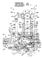
- FIG. 1 is an external view of a gas turbine engine and control system having an embodiment of the present invention;
- FIG. 2 is a partially sectioned side view of a gas turbine engine having an embodiment of the present invention;
- FIG. 3 is a partially sectioned end view taken through line 3-3 of FIG. 2;
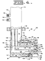
- FIG. 4 is an enlarged sectional view of a dual fuel injector use in one embodiment of the present invention;
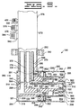
- FIG. 5 is an enlarged sectional view of an alternate embodiment of a single fuel injector used in one embodiment of the present invention; and
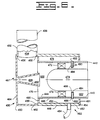
- FIG. 6 is an enlarged sectional view of an alternate embodiment of a single fuel injector used in one embodiment of the present invention.
- In reference to FIG. 1 and 2, a
gas turbine engine 10 having acontrol system 12 for reducing nitrous oxide emissions therefrom is shown. Thegas turbine engine 10 has anouter housing 14 having therein a plurality ofopenings 16, of which only one is shown, having a preestablished position and relationship one to another. A plurality of threadedholes 18 are positioned relative to the plurality ofopenings 16. Thehousing 14 further includes at least asingle aperture 19 therein and acentral axis 20. Thehousing 14 is positioned about a compressor section 22 centered about theaxis 20, aturbine section 24 centered about theaxis 20 and a combustor section 26 positioned operatively between the compressor section 22 and theturbine section 24. Theengine 10 has aninner case 28 coaxially aligned about theaxis 20 and is disposed radially inwardly of the compressor section 22,turbine section 24 and the combustor section 26. Theturbine section 24 includes apower turbine 30 having an output shaft, not shown, connected thereto for driving an accessory component such as a generator. Another portion of theturbine section 24 includes agas producer turbine 32 connected in driving relationship to the compressor section 22. The compressor section 22, in this application, includes an axial staged compressor 34 having a plurality of rows ofrotor assemblies 36, of which only one is shown. When theengine 10 is operating, the compressor 34 causes a flow of compressed air exiting therefrom designated by the arrows 38. As an alternative, the compressor section 22 could include a radial compressor or any source for producing compressed air. In this application, the combustor section 26 includes anannular combustor 40 being radially spaced a preestablished distance from theouter housing 14 and theinner case 28. Thecombustor 40 is supported from theinner case 28 in a conventional manner. Thecombustor 40 has a generally cylindricalouter shell 50 being coaxially positioned about thecentral axis 20, a generally cylindricalinner shell 52 having anouter surface 53 being coaxial with theouter shell 50, an inlet end 54 having a plurality of generally evenly spacedopenings 56 therein and anoutlet end 58. In this application, thecombustor 40 is constructed of a plurality of generallyconical segments 60. Theouter shell 50 has anouter surface 62 and aninner surface 64 extending generally between the inlet end 54 and theoutlet end 58. Each of theopenings 56 has aninjector 66 having acentral axis 68 positioned therein, in the inlet end 54 of thecombustor 40. The area between theouter housing 14 and theinner case 28 less the area of the combustor section 26 forms a preestablished flow orcooling area 70 through which the major portion of the compressed air 38 will flow. In this application, approximately 50 to 70 percent of the compressed air 38 is used for cooling. As an alternative to theannular combustor 40, a plurality of can type combustors could be incorporated without changing the gist of the invention. - As best shown in FIG. 4, in this application each of the
injectors 66 are of the single gaseous fuel type. Each of theinjectors 66 is supported from thehousing 14 in a conventional manner. For example, an outertubular member 72 has apassage 74 therein. Thetubular member 72 includes aninlet end portion 76 and anoutlet end portion 78. Thetubular member 72 extends radially through one of the plurality ofopenings 16 in theouter housing 14 and has amounting flange 80 extending therefrom. Theflange 80 has a plurality ofholes 82 therein in which a plurality ofbolts 84 threadedly attach to the threadedholes 18 in theouter housing 14. Thus, theinjector 66 is removably attached to theouter housing 14. Theinjector 66 includes a generally cylindricalouter casing 86 having awall 88 defining aninner surface 90 and anouter surface 92. Thecasing 86 is coaxially positioned about thecentral axis 68 and has afirst end 94 closed by aplate 96 and a secondopen end 98. Anaperture 100 defined in thewall 88 has thetubular member 72 fixedly attached therein. Theaperture 100 is defined near thefirst end 94 and extends between theouter surface 92 and theinner surface 90. A plurality ofswirlers 102 each have a preestablished length and shape, anouter portion 104 generally evenly positioned about theinner surface 90 of thecasing 86 intermediate theaperture 100 and thesecond end 98 is attached to theinner surface 90. Aninner portion 106 of each of the plurality ofswirlers 102 is attached to aninner member 108 which is coaxially positioned about thecentral axis 68. Theinner member 108 includes anend cap 110 and amain body 112 having afirst end 114, asecond end 116 and an external steppedsurface 118 extending between the ends 114,116. Theend cap 110 includes afirst end 120, asecond end 122 and a concaveinner surface 124 extending from thefirst end 120 toward thesecond end 122. Thefirst end 120 of theend cap 110 is attached to themain body 112 at thesecond end 116. Theinner member 108 further includes a generallycylindrical shell 126 coaxially positioned about thecentral axis 68 and having afirst end 128 and asecond end 129. Thefirst end 128 is attached to theexternal surface 118 intermediate the first and second ends 114,116 of themain body 112. Thefirst end 114 of themain body 112 is also attached to theplate 96 or as an alternative may be integrally formed therewith. Afirst chamber 130 is defined by theend plate 96, a portion of theinner surface 90 of thecasing 86, the plurality ofswirlers 102 and a portion of theexternal surface 118 of themain body 112. A plurality of holes orpassages 131 in theplate 96 communicate with thefirst chamber 130 and have a combined predetermined total area. In this application the predetermined total area of the plurality ofholes 131 is equal to approximately 50 to 70 percent of the total maximum flow of compressed air passing through theinjector nozzle 66. A second chamber ormain air passage 132 is defined by the plurality ofswirlers 102, a portion of theinner surface 90 of thecasing 86, a portion of theshell 126 and the secondopen end 98 of thecasing 86 and thesecond end 129 of theshell 126. - A first gaseous fuel gallery or
annular groove 134 is defined intermediate the first and second ends 114,116 of themain body 112 and extends inwardly from theexternal surface 118 of the main body 112 a preestablished distance. A portion of theshell 126 is positioned over a portion of the external steppedsurface 118 in sealing relationship and further defines the firstannular groove 134. Amain gas passage 136 communicates between the firstannular groove 134 and theexternal surface 118 and exits near thefirst end 114 of themain body 112. Afirst gas tube 138 is at least partially positioned within thepassage 74 of thetubular member 72 and has afirst end portion 140 fixedly attached within themain gas passage 136 near the exit thereof at theexternal surface 118. Asecond end 142 of thefirst gas tube 138 sealingly exits thepassage 74 through the wall of thetubular member 72 and has a threaded fitting 144 attached thereto for communicating with a source of gaseous combustible fuel, not shown. A plurality ofholes 148 are radially spaced about theshell 126 and communicate between the firstannular groove 134 and thesecond chamber 132. Positioned in each of the plurality ofholes 148 is a hollow cylindrical spokemember 150 having a preestablished length, afirst end 152 which is closed and asecond end 154 which is open. Thesecond end 154 of thespoke members 150 is positioned in each of the plurality ofholes 148 and thespoke member 150 extends radially outward from theshell 126. Thespoke member 150 has a plurality ofpassages 156 therein which are axially spaced along the cylinder. The plurality ofpassages 156 are positioned in such a manner so as to inject gaseous fuel in a predetermined manner into thesecond chamber 132 and the firstclosed end 152 is positioned radially inwardly from theinner surface 90 of thecasing 86. The plurality ofpassages 156 are in fluid communication with the hollow portion of thecylindrical spoke member 150, the firstannular groove 134 and themain gas passage 136. Thus, ameans 160 for passing the main source of fuel through theinjector 66 is formed. The means 160 for passing the main source of fuel includes themain air passage 132, the plurality ofspoke members 150, the firstannular groove 134, themain gas passage 136 , thefirst gas tube 138 and the source of gaseous combustible fuel. - A
pilot chamber 164 is defined by theconcave surface 124 within the internal configuration of theend cap 110 of theinner member 108. Thesecond end 122 of theend cap 110 has a plurality ofexit passages 168, radially spaced thereabout, defined therein and in fluid communication with thepilot chamber 164. Each of the plurality ofexit passages 168 is at an oblique angle to thecentral axis 68 of theinjector nozzle 66. Apilot gas passage 170 communicates between thepilot chamber 164 and theexternal surface 118 of themain body 112 near thefirst end 114 of themain body 112. Asecond gas tube 172 is at least partially positioned within thepassage 74 of thetubular member 72 and has afirst end 174 fixedly attached within thepilot gas passage 170 near the exit thereof at theexternal surface 116. Asecond end 176 of thesecond gas tube 172 sealingly exits thepassage 74 through the wall of thetubular member 72 and has a threaded fitting 178 attached thereto for communicating with a source of gaseous combustible fuel, not shown. The source of gaseous combustible fuels may be the same or an alternate sources from that supplied to themain gas passage 136. - A set of
swirlers 180 each having a preestablished length and shape are generally evenly spaced and positioned inwardly about theshell 126 and outwardly from theend cap 110. The set ofswirlers 180 are spaced a preestablished distance from a portion of the external steppedsurface 118 and define a second fuel gallery orannular groove 182 between a portion of the external steppedsurface 118, theshell 126 and the set ofswirlers 180. Asecondary passage 184 communicates between the secondannular groove 182, thefirst end 114 of themain body 112 and further passes through theplate 96. Theinjector nozzle 66 further includes ameans 186 for introducing secondary air into theinjector nozzle 66. The means for introducing secondary air into theinjector nozzle 66 includes thesecondary passage 184 and the plurality ofholes 131 in theplate 96. - As an alternative, and best shown in FIG. 5, a dual
fuel type injector 190, gaseous and liquid, can be used in place of the singlegaseous fuel injector 66. Where applicable, the nomenclature used to identify the dualfuel type injector 190 is identical to that used to identify the single gaseousfuel type injector 66; however, the numbers are different. Each of theinjectors 190 has acentral axis 192 and is supported from theouter housing 14 in a conventional manner. For example, an outertubular member 272 has apassage 274 therein. Thetubular member 272 includes aninlet end portion 276 and anoutlet end portion 278. Thetubular member 272 extends radially through one of the plurality ofopenings 16 in theouter housing 14 and has a mountingflange 280 extending therefrom. Theflange 280 has a plurality ofhole 282 therein in which a plurality of bolts, not shown, threadedly attach to the threadedholes 18 in theouter housing 14. Thus, theinjector 190 is removably attached to theouter housing 14. Theinjector 190 includes a generally cylindricalouter casing 286 having awall 288 defining aninner surface 290 and anouter surface 292. Thecasing 286 is coaxially positioned about thecentral axis 192 and has afirst end 294 which is closed by aplate 296 and a secondopen end 298. Anaperture 300 defined in thewall 288 has thetubular member 272 fixedly attached therein. Theaperture 300 is defined near thefirst end 294 and extends between theouter surface 292 and theinner surface 290. A plurality ofswirlers 302 each have a preestablished length and shape, anouter portion 304 generally evenly spaced about theinner surface 290 of thecasing 286 intermediate theaperture 300 and thesecond end 298 is attached to theinner surface 290. Aninner portion 306 of each of the plurality ofswirlers 302 is attached to aninner member 308 which is coaxially positioned about thecentral axis 192. Theinner member 308 includes anend cap 310 and amain body 312 having afirst end 314, asecond end 316 and an external steppedsurface 318. Theend cap 310 includes afirst end 320, asecond end 322 and a concaveinner surface 324 extending from thefirst end 320 toward thesecond end 322. Thefirst end 320 of theend cap 310 is attached to themain body 312 near thesecond end 316. Theinner member 308 further includes a generallycylindrical shell 326 which is coaxially positioned about thecentral axis 192 and has afirst end 328 and asecond end 329. Thefirst end 328 is attached to theexternal surface 318 intermediate the first and second ends 314,316 of themain body 312. Thefirst end 314 of themain body 312 is also attached to theplate 296 or as an alternative may be integrally formed therewith. Afirst chamber 330 is defined by theend plate 296, a portion of theinner surface 290 of thecasing 286, the plurality ofswirlers 302 and a portion of theexternal surface 318 of themain body 312. A plurality of holes orpassages 331 in theplate 296 communicate with thefirst chamber 330 and have a combined predetermined total area. In this application the predetermined total area of the plurality ofholes 331 is equal to approximately 50 to 75 percent of the total maximum flow of compressed air passing through theinjector nozzle 190. A second chamber ormain air passage 332 is defined by the plurality ofswirlers 302, a portion of theinner surface 290 of thecasing 286, a portion of theshell 326, the secondopen end 298 of thecasing 286 and thesecond end 329 of theshell 326. A main gaseous fuel gallery or firstannular groove 334 is defined intermediate the first and second ends 314,316 and extends inwardly from theexternal surface 318 of the main body 312 a preestablished distance. A portion of theshell 326 is positioned over a portion of the external steppedsurface 318 in sealing relationship and further defines the firstannular groove 334. Amain gas passage 336 communicates between the firstannular groove 334 and exits theexternal surface 318 near thefirst end 314 of themain body 312. Afirst gas tube 338 is at least partially positioned within thepassage 274 of thetubular member 272 and has afirst end portion 340 fixedly attached within themain gas passage 336 near the exit thereof at theexternal surface 318. Asecond end 342 of thefirst gas tube 338 sealingly exits thepassage 274 through the wall of thetubular member 272 and has a threaded fitting 344 attached thereto for communicating with a source of gaseous combustible fuel, not shown. A plurality ofholes 348 are defined within theshell 326, radially spaced about theshell 326 and communicate between the firstannular groove 334 and thesecond chamber 332. Positioned in each of the plurality ofholes 348 is a hollow cylindrical spokemember 350 having a preestablished length, afirst end 352 which is closed and asecond end 354 which is open. Thesecond end 354 of thespoke member 350 is positioned in each of the plurality ofholes 348 and thespoke member 350 extends radially outward from theshell 326. Thespoke member 350 has a plurality ofpassages 356 therein which are axially spaced along the cylinder. The plurality ofpassages 356 are in fluid communication with the hollow portion of thecylindrical spoke member 350, the firstannular ring 334 and themain gas passage 336. The plurality ofpassages 356 are positioned in such a manner so as to inject gaseous fuel in a predetermined manner into thesecond chamber 332 and the firstclosed end 352 is positioned radially inwardly from theinner surface 290 of thecasing 286. - A
pilot chamber 364 is defined by theconcave surface 324 within the internal configuration of theend cap 310 of theinner member 308. Thesecond end 322 of theend cap 310 has a plurality ofexit passages 368 radially spaced thereabout, defined therein and in fluid communication with thepilot chamber 364. Each of the plurality ofexit passages 368 is at an oblique angle to thecentral axis 192 of theinjector nozzle 190. Apilot gas passage 370 communicates between thepilot chamber 364 and theexternal surface 318 of themain body 312 near thefirst end 314 of themain body 312. Asecond gas tube 372 is at least partially positioned within thepassage 274 of thetubular member 272 and has afirst end 374 fixedly attached within thepilot gas passage 370 near the exit thereof at theexternal surface 316. Asecond end 376 of thesecond gas tube 372 sealingly exits thepassage 274 through the wall of thetubular member 272 and has a threaded fitting 378 attached thereto for communicating with a source of gaseous combustible fuel, not shown. The source of gaseous combustible fuels may be the same as the source supplied to themain gas passage 336 or an alternate sources. A set ofswirlers 380 each having a preestablished length and shape are generally evenly spaced and positioned inwardly about theshell 326 and outwardly from theend cap 310. The set ofswirlers 380 are spaced a preestablished distance from a portion of the external steppedsurface 318 and define a secondannular groove 382 between the external steppedsurface 318, theshell 326 and the set ofswirlers 380. Asecondary passage 384 communicates between the secondannular groove 382, thefirst end 314 of themain body 312 and further passes through theplate 296. Theinjector nozzle 190 further includes ameans 385 for introducing secondary air into theinjector nozzle 190. In this application, themeans 385 for introducing secondary air into theinjector nozzle 190 includes thesecondary passage 384 and the plurality ofholes 331 in theplate 296. A third fuel gallery orannular groove 390 is defined intermediate the firstannular groove 334 and the secondannular groove 382. The thirdannular groove 390 extends inwardly from theexternal surface 318 of the main body 312 a preestablished distance. A portion of theshell 326 is positioned over a portion of the external steppedsurface 318 in sealing relationship and further defines the thirdannular groove 390. Aliquid fuel passage 392 communicates between the thirdannular groove 390 and theexternal surface 318 and exits near thefirst end 314 of themain body 312. Aliquid fuel tube 394 is at least partially positioned within thepassage 274 of thetubular member 272 and has afirst end portion 396 fixedly attached within theliquid fuel passage 392 near the exit thereof at theexternal surface 318. Asecond end 398 of theliquid fuel tube 394 sealingly exits thepassage 274 through the wall of thetubular member 272 and has a threaded fitting 400 attached thereto for communicating with a source of liquid combustible fuel, not shown. A plurality ofholes 402 are axially spaced between the plurality ofholes 348 and thesecond end 329 of theshell 326. The plurality ofholes 402 are generally evenly, circumferentially and radially spaced about theshell 326 and communicate between the thirdannular groove 390 and the second chamber 232. - As best shown in Fig. 6, an alternate single
fuel injection nozzle 430 is shown. Thisinjection nozzle 430 includes an outertubular member 432 having apassage 434 therein. Thetubular member 432 extends radially through one of the plurality ofopenings 16 in thehousing 14 and has a mounting flange, not shown extending therefrom. The flange has a plurality of holes therein to receive a plurality of bolts for threadedly attaching within the threadedholes 16 in thehousing 14. Thus, thenozzle 430 is removably attached to thehousing 14. Thetubular member 432 further includes aninlet end portion 436 and anoutlet end portion 438. Thenozzle 430 further includes a generallycylindrical casing 440 having awall 442 defining aninner surface 444 and anouter surface 446, ashell 448 defining aninner surface 450 and anouter surface 452, afirst end portion 454 and asecond end portion 458. A channel shapedmember 460 includes aninlet portion 462 extending from abase 464. Theinlet portion 462 is attached to theshell 448 of thecasing 440 near thesecond end portion 458 and has anaperture 466 defined therein. Theinlet portion 462 defines ameans 467 for introducing secondary air into theinjector nozzle 430. - In this application, the means for introducing secondary air is an orifice or
passage 468 positioned in thebase 464, defined by theinlet portion 462 and centered about the axis of theinjector nozzle 430. Theorifice 468 has a preestablished area. Theinlet portion 462 is positioned in spaced relationship to theinner surface 444 of theinner wall 442 of thecasing 440 and forms an orifice orpassage 470 therebetween having a preestablished area. Theorifice 470 is formed between thecasing 440 and theinlet portion 462. Theinlet end portion 436 of theouter tube member 432 is coaxially aligned with theaperture 466 and is fixedly attached to thechannel member 460. Thetube passage 434 is in fluid communication with theorifice 470. A plurality ofswirler vanes 472 having a preestablished length and shape are generally evenly spaced about theinner surface 444 of theinner wall 442 and have one end fixedly attached thereto. Adeflector member 474 is radially, inwardly, coaxially positioned within thecasing 440 and is fixedly attached to the other end of each of the plurality ofswirler vanes 472. A fourth fuel gallery orannular ring 478 is formed externally of thecasing 440. For example, the fourthannular ring 478 is defined by theouter surface 446 of theinner wall 442, aplate 480 positioned at theinlet end portion 458, theinner surface 450 of theouter wall 448 and aplate 481 positioned at theoutlet end portion 454. Positioned in theinner wall 442 of thecasing 440 intermediate the end 454,458 is a plurality ofholes 482 extending radially between theinner surface 444 and theouter surface 446. Positioned in each of the plurality ofholes 482 and extending radially inwardly from theinner surface 444 of theinner wall 442 is a plurality of hollow spokemembers 484. Each of thespoke members 484 have a preestablished length, afirst end 486 which is closed and asecond end 488 which is open. Thesecond end 488 is positioned in each of the plurality ofholes 482. A plurality ofpassages 490 are axially spaced along each of thespoke members 484 and are in fluid communication with the hollow portion of each of thespoke members 484. Theinjection nozzle 430 further includes ameans 492 for communicating between the source of fuel and themain fuel gallery 478. The means 492 for communicating includes atube 494 being in fluid communication between themain fuel gallery 478 and the source of fuel. One end of thetube 494 is attached to the fourthannular ring 478 and the other end of thetube 494 sealing exits thehousing 14 for communicating with a source of fuel. - The
injection nozzle 430 further includes anair passage 500 having a preestablished total area. Thepassage 500 is formed radially inwardly of theinner surface 444 of theinner wall 442 of themain body 440 and extends axially intermediate theinlet end portion 458 and theoutlet end portion 454. Thedeflector member 474 is positioned within theair passage 500 and restricts the amount of compressed air flowing therethrough and forms a second chamber ormain air passage 502 having a preestablished area. Themain air passage 502 is positioned between theinner surface 444 and thedeflector member 474. In this application, approximately 50 to 75 percent of the total maximum flow of compressed air passing through theinjector nozzle 430 enters into the preestablished area of theair passage 500. The flow of compressed air through themain air passage 502 into thecombustor 40 is an amount sufficient, with the addition of an appropriate amount of fuel, to support full load operation of thegas turbine engine 10. The plurality ofpassages 490 are positioned in such a manner so as to inject fuel in a predetermined manner into themain air passage 502 and the firstclosed end 486 is positioned radially inwardly from theinner surface 444 of theinner wall 442. Furthermore, in this application the preestablished effective cross sectional area of theorifice 470, which is in fluid communication with theair passage 500, is equal to approximately 50 to 75 percent of the effective cross sectional area of the preestablished area between themain body 440 and thedeflector member 474. - As best shown in Figs. 1 and 2, the
control system 12 for reducing nitrogen oxide, carbon monoxide and unburned hydrocarbon emissions from thegas turbine engine 10 includes ameans 560 for directing a portion of the flow of compressed air exiting the compressor section 22 through the injection nozzles 66,190,430 into theinlet end 48 of thecombustor 40. The means 560 for directing a portion of the flow of compressed air includes theouter housing 14 and theinner case 28 and theouter shell 44, theinlet end 48 and theinner shell 46 of the combustor section 26. The preestablished spaced relationship of the outer andinner shells combustor 40 to theouter housing 14 and theinner case 28 which forms thepreestablished flow area 70 between the combustor 40, and theouter housing 14 and the inner case 26 is also a part of themeans 560 for directing. - As best shown in FIGS. 1, 2 and 3, the
control system 12 for reducing nitrogen oxide, carbon monoxide and unburned hydrocarbon emissions from theengine 10 further includes a manifold 562 having apassage 564 therein. The manifold 562 is positioned externally of and encircles theouter housing 14. A plurality ofopenings 566 in the manifold correspond in location to the location of each of the tubular members 72,272,432. The tubular members 72,272,432 form a part of ameans 568 for ducting and are attached in fluid communication with the plurality ofopenings 566 in themanifold 562. Thus, the tube passage 74,274,434 of the tubular member 72,272,432 is in fluid communication with the compressed air inside thepassage 564 within themanifold 562. The means 568 for ducting includes a plurality of elbows, flanges andconnectors 570. The manifold 562 further includes at least one primary inlet opening 572 having aduct 574 attached thereto. Theduct 574 has apassage 576 defined therein which is in,communicates with thepassage 564 within themanifold 562 and thepreestablished flow areas 70 between the combustor 40, and theouter housing 14 and the inner case 26 by way of theaperture 19 within theouter housing 14. Attached within theduct 574 is avalve 578. In this application, thevalve 578 is of the conventional butterfly type but could be of any conventional design. Thevalve 578 includes ahousing 580 having apassage 582 therein. Further included in thehousing 580 is a throughbore 584 and a pair of bearings, not shown, are secured in thebore 584. Ashaft 586 is rotatably positioned within the bearings and has athrottling mechanism 588 attached thereto and positioned within thepassage 582. Theshaft 586 has afirst end 590 extending externally of thehousing 580. Alever 592 is attached to thefirst end 590 of theshaft 586 and movement of thelever 592 causes thethrottling mechanism 588 to move between aclosed position 594 and anopen position 596. - Further included with the
control system 12 for reducing nitrogen oxide, carbon monoxide and unburned hydrocarbon emissions is ameans 598 for controllably varying the amount of air directed into thecombustor 40. The means 598 for controllably varying is operative positioned between the source of compressed air 22 and thecombustor 40. In this application, themeans 598 is positioned between the compressor 22 and thecombustor 40. The air entering into the injection nozzle 66,190,430 is restricted or controlled at a minimum flow when theengine 10 is operating at lower power or fuel levels. The means 598 for varying the amount of air directed into thecombustor 40 includes the following components. The first chamber 130,330 and the second chambers 132,332 having the preestablished area formed between the outer cylindrical casing 86,286 and the inner member 108,308 of each injector nozzle 66,190. Themain air passage 502 having the preestablished area and formed between themain body 440 and thedeflector member 474 and theorifice 470 having the preestablished area formed between thecasing 440 and theinlet portion 462 of theinjector nozzle 430. The passage 74,274,434 within the tubular member 72,284,432 and thepassage 564 in the manifold 562 are also a part of thecontrol system 12. Thepassage 576 within theduct 574 and thepassage 582 in thehousing 580. Furthermore, thethrottling mechanism 588 within thepassage 582 is included in themeans 598 for controllably varying the amount of air directed into thecombustor 40. - Further included with the
control system 12 for reducing nitrogen oxide, carbon monoxide and unburned hydrocarbon emissions is ameans 610 for monitoring and controlling the portion of the flow of compressed air controllably directed to the injection nozzle 66,190,430. The means 610 for monitoring and controlling includes asensor 612 positioned within theengine 10 which monitors thepower turbine 30 inlet temperature. As an alternative, many parameters of the engine such as load or speed could be used as the monitored parameter. Thesensor 612 is connected to a control box orcomputer 614 by a plurality ofwires 616 wherein a signal from thesensor 612 is interpreted and a second signal is sent through a plurality ofwires 618 to apower cylinder 620. In this application, thepower cylinder 620 is a hydroelectric cylinder, but as an alternative could be an electric solenoid or any other equivalent device. Thepower cylinder 620 moves thelever 592 and thecorresponding throttling mechanism 588 between theopen position 596 and theclosed position 594. When thepower turbine 30 inlet temperature reaches a preestablished temperature, which corresponds to a combustion temperature in the range of about 2700 to 3140 degrees Fahrenheit, (1480°C to 1730°C) thevalve 578 having the throttling mechanism therein maintaining the amount of compressed air controllably directed to the injector 66,190,430. In this application, the movement of thethrottling mechanism 588 is infinitely variable between theopen position 596 and theclosed position 594. However, as an option, the movement of thethrottling mechanism 588 can be movable between theclosed position 594 and theopen position 596 through a plurality of preestablished stepped positions. - Although not shown, an alternative to a
single duct 574 and asingle valve 578 having athrottling mechanism 588 therein, could include a plurality ofducts 574 interconnecting thepreestablished flow area 70 with thepassage 564 within themanifold 562 without changing the gist of the invention. For example, if each of the plurality ofducts 574 have thevalve 578 and thethrottling mechanism 588 therein, a means for interconnecting thevalves 578 will be required. One alternative for the means for interconnecting could include a plurality of thepower cylinders 620 each having a common activation system which would insure that the position of eachthrottling mechanism 588 is simultaneously uniformly activated or controlled. Another alternative for the means for interconnecting could include a plurality of levers interconnecting each of thethrottling mechanism 588 of eachvalve 578. One of the plurality of levers would have thepower cylinder 620 attached thereto and would simultaneously uniformly activate thethrottling mechanism 588. Another option could include a pair of thevalves 578 being connected by a lever. Each of the levers would have the power cylinder connected thereto and would simultaneously uniformly activate thethrottling mechanism 588 of eachvalve 578. Each of the pair ofvalves 578 would require apower cylinder 620 to activate thevalve 578. The power cylinders would have a common activation system so that the position of eachthrottling mechanism 588 is uniformly activated or controlled. - In use the
gas turbine engine 10 is started and allowed to warm up and is used to produce either electrical power, pump gas, turn a mechanical drive unit or another application. As the demand for load or power produced by the generator is increased, the load on theengine 10 is increased and thecontrol system 12 for reducing nitrogen oxide, carbon monoxide and unburned hydrocarbon emission is activated. In the start-up and warm-up condition, thethrottling mechanism 588 of thevalve 578 is positioned in either the partly open 596 or closed 594 position and the minimum amount of compressed air is directed into the injection nozzle 66,190,430 and the minimum amount of compressed air enters thecombustor 40. During the start-up and warm-up condition the engine is in a high emissions mode and uses primarily pilot only fuel. For example, the majority of the compressed air from the compressor section 22 flows between theouter housing 14 and theinner case 28 into the preestablished flow or coolingarea 70 formed between theouter housing 14 and theinner case 28 less the area of the combustor section 26. A small portion of the compressed air from the compressor section 22 flows through the secondary passage 184,384,468 into the second annular groove 182,382 or theair passage 500 and exits through the passages 186,368,502 into thecombustor 40. When pilot fuel is being used, fuel enters through the second gas tube 172,372,494 travels along the pilot gas passage 170,370,479 into the pilot chamber 164,364,502. From thepilot chamber 164, the pilot fuel exits through the plurality of exit passages 168,368 and intermixes with the small portion of compressed air entering through the secondary passage 184,384,468 in the injector nozzle 66,190,430. An additional small portion of the compressor air also enters through the plurality of holes 131,331 in the end plate 96,296, communicates with the first chamber 130,330,500 passes through the plurality of swirlers 102,302,472 into the second chamber 132,332,502 and exits into thecombustor 40. Furthermore, within thecombustor 40, the air which has entered through the plurality of holes 131,331,468 further mixes with the pilot fuel and air mixture and is burned during the high emissions mode. In this mode the remainder of the air from the compressor flows through thepreestablished flow area 70. - With the
throttling mechanism 588 in the fullyopen position 596, the maximum allowable flow of compressed air is drawn from thepreestablished flow area 70 and is directed through theopenings 19 in theouter housing 14 into thepassage 576 within theduct 574 through thevalve 578 and into thepassage 564 within themanifold 562. From thepassage 564, the air is communicated into the tube passages 74,274,434 within the tubular members 72,272,432 and into the injector nozzles 66,190,430. - In the single gaseous fuel type injector nozzle 66,430 and the dual fuel
type injector nozzle 190, the position of thethrottling mechanism 588 intermediate theclosed position 594 and theopen position 596 determines the amount of primary air from the compressor section 22 that is to be mixed with fuel within the injector nozzle 66,190,430. Thus, the fuel/air ratio and the temperature within thecombustor 40 is controlled and the formation of nitrogen oxide, carbon monoxide and unburned hydrocarbon is minimized. As the load on theengine 10 is increased, the amount of fuel injected into the combustor section 26 is increased, the fuel/air ratio changes and the combustion temperature within the combustor section 26 is increased. The results of the increase of combustion temperatures causes the temperature of the gases at thepower turbine 30 inlet to increase. Thesensor 612 sends a signal through the plurality ofwires 616 to thecomputer 614 which is interpreted to indicated an increase in thepower turbine 30 inlet temperature and a second signal is sent through the plurality ofwires 618 to thepower cylinder 620 causing thelever 592 andthrottling mechanism 588 to move toward theopen position 596. This increases the amount of air directed into the injector nozzle and increases the amount of air directed to thecombustor 40. The continued monitoring by thesensor 612 and interpretation by thecomputer 614 keeps the air/fuel ratio relatively constant. In order to accelerate, the air/fuel ratio must change. For example, in the air/fuel ratio, the relationship of the amount of fuel increases whereas the air remains constant. However, thecontrol system 12 is adapted to control the temperature of combustion and the potential resulting increased emissions of nitrogen oxide, carbon monoxide and unburned hydrocarbon during combustion temperatures of generally between about 2700 to 3140 degrees Fahrenheit (1480°C to 1730°C). The temperature of the gases entering into theturbine section 24 is monitored constantly and if the temperature reaches the range of between about 2700 to 3140 degrees Fahrenheit (1480°C to 1730°C) the temperature remains at this high temperature for only a short period of time. Thus, the emissions are controlled by the variation or change in air/fuel ratio resulting in high combustion temperatures. As theengine 10 accelerates, the fullyopen position 596 is reached wherein thevalve 578 has thelever 592 andthrottling mechanism 588 fully opened increasing the flow of air through thepassage 576 drawing a greater percentage of compressor air from theflow passage 70. Thus, the flow of compressed air through the the second chamber 132,332 and theorifice 470 is increased. - Other aspects, objectives and advantages of this invention can be obtained from a study of the drawings, the disclosure and the appended claims.
Claims (28)
- A control system (12) for reducing the formation of exhaust emissions during operation of a gas turbine engine (10), the engine (10) including a source of compressed air (22), a combustor (40) and a turbine (30) arranged in serial order and at least one fuel injection nozzle (66,190,430) for directing a combustible fuel and compressed air into the combustor (40); the control system (12) comprising means (560) for directing a portion of the flow of compressed air exiting the compressor section (22) through the injection nozzle (66,190,430) into the combustor (40) in an amount sufficient, with the addition of an appropriate amount of fuel, to support full fuel operation of the gas turbine engine (10) at rated speed; and means (598) for controllably varying the amount of air directed into the combustor (40) by directing a portion of the air from the compressor section (22) into the injection nozzle (66,190,430) when the engine (10) is operated at power levels between low fuel and high fuel conditions, the means (598) for controllably varying being operatively positioned between the source of compressed air (22) and the fuel injection nozzle (66,190,430) characterised by the means (560) including a pre-established flow area (70) formed between an outer housing (14) and an inner case (28), less the area of the combustor (40), a manifold (562) and a duct (574) which communicates with the pre-established flow area (70) and the manifold (562).
- A control system (12) for reducing exhaust emissions from a gas turbine engine (10) according to claim 1, wherein the means (598) for controllably varying the amount of air directed into the combustor (40) includes a throttling mechanism (588) operatively positioned between the source of compressed air (22) and the injection nozzle (66,190,430).
- A control system (12) for reducing exhaust emissions from a gas turbine engine (10) according to claim 2, wherein the injection nozzle (66,190,430) includes means (186,385,467) for introducing secondary air through the injection nozzle (66,190,430) into the combustor (40).
- A control system (12) for reducing exhaust emissions from a gas turbine engine (10) according to claim 3, wherein the means (186,385,467) for introducing secondary air into the combustor (40) includes a secondary passage (184,131;384,331;468) having a preestablished area.
- A control system (12) for reducing exhaust emissions from a gas turbine engine (10) according to claim 4, wherein the preestablished area of the secondary passage (184,384,468) is sized allowing about 5 percent of the total maximum flow of compressed air passing through the injector nozzle (66,190,430) to enter into the injection nozzle (66,190,430).
- A control system (12) for reducing exhaust emissions from a gas turbine engine (10) according to claim 2, wherein the throttling mechanism (588) includes a valve (578) connected to the injection nozzle (66,190,430) by a plurality of passages (74,564,576;274,564,576;334,564,576).
- A control system (12) for reducing exhaust emissions from a gas turbine engine (10) according to claim 6, wherein the valve (578) includes a butterfly type valve.
- A control system (12) for reducing exhaust emissions from a gas turbine engine (10) according to claim 7, wherein the valve (578) includes a housing (580) and a control lever (592) positioned externally of the housing (580).
- A control system (12) for reducing exhaust emissions from a gas turbine engine (10) according to claim 8, wherein the valve (578) has a throttling mechanism (588) being movable between a closed position (594) and an open position (596), the throttling mechanism (588) being infinitely variable between the open position (596) and the closed position (594).
- A control system (12) for reducing exhaust emissions from a gas turbine engine (10) according to claim 8, wherein the valve (578) has a throttling mechanism (588) being movable between an open position (596) and a closed position (594) through a plurality of pre-established stepped positions.
- A control system (12) for reducing exhaust emissions from a gas turbine engine (10) according to any one of the preceding claims, wherein the means (560) for directing air from the source of compressed air (22) through the injection nozzle (66,190,430) into the combustor (40) includes the combustor (40) positioned within the outer housing (14) and the preestablished flow area (70).
- A control system (12) for reducing exhaust emissions from a gas turbine engine (10) according to claim 11, wherein the preestablished flow area (70) within the housing (14) allows between 50 to 75 percent of the compressed air to flow therethrough.
- A control system (12) for reducing exhaust emissions from a gas turbine engine (10) according to claim 12, wherein the combustor (40) includes an outer shell (44) and an inner shell (46), each of the outer and inner shells (44,46) having an outer surface (54,56) respectively in which the air flowing through the preestablished flow area (70) passes thereover and cools the combustor (40).
- A gas turbine engine (10) having a control system (12) for reducing the formation of exhaust emissions during operation of a gas turbine engine (10), the engine (10) including a source of compressed air (22), a combustor (40) and a turbine (30) arranged in serial order and at least one fuel injection nozzle (66,190,430) directing a combustible fuel and compressed air into the combustor (40); the control system (12) comprising means (560) for directing air from the source of compressed air (22) through the injection nozzle (66,190,430) into the combustor (40) in an amount sufficient, with the addition of an appropriate amount of fuel, to support full fuel operation of the gas turbine engine (10) at rated speed; and means (598) for controllably varying the amount of air directed into the combustor (40) by directing a portion of the air from the compressor section (22) into the injection nozzle (66,190,430) when the engine (10) is operated at power levels between low fuel and high fuel conditions, the means (598) for controllably varying being operatively positioned between the source of compressed air (22) and the combustor (40) characterised by the means (560) including a pre-established flow area (70) formed between an outer housing (14) and an inner case (28), less the area of the combustor (40), a manifold (562) and a duct (574) which communicates with the pre-established flow area (70) and the manifold (562).
- A gas turbine engine (10) according to claim 14, wherein the means (598) for controllably varying the amount of air directed into the combustor (40) includes a throttling mechanism (588) operatively positioned between the source of compressor air (22) and the injection nozzle (66,190,430).
- A gas turbine engine (10) according to claim 15, wherein the injection nozzle (66,190,430) includes means (186,385,467) for introducing secondary air through the injection nozzle (66,190,430) into the combustor (40).
- A gas turbine engine (10) according to claim 16, wherein the means (186,385,467) for introducing secondary air into the combustor (40) includes a secondary passage (184,131;384,331;468) having a preestablished area.
- A gas turbine engine (10) according to claim 17, wherein the preestablished area of the secondary passage (184,384,468) is sized allowing about 5 percent of the total maximum flow of compressed air passing through the injector nozzle (66,190,430) to enter into the injection nozzle (66,190,430).
- A gas turbine engine (10) according to claim 15, wherein the throttling mechanism (588) includes a valve (578) connected between the source of compressed air (22) and the injection nozzle (66,190,430).
- A gas turbine engine (10) according to claim 19, wherein the connection between the valve (578) and the injection nozzle (66,190,430) includes a plurality of passages (74,564,576;274,564,576;434,564,576).
- A gas turbine engine (10) according to claim 20, wherein the valve (578) includes a butterfly type valve.
- A gas turbine engine (10) according to claim 19, wherein the valve (578) includes a housing (580) and a lever (592) positioned externally of the housing (580).
- A gas turbine engine (10) according to claim 19, wherein the throttling mechanism (588) is movable between an open position (596) and a closed position (594), the throttling mechanism (588) being infinitely variable between the open position (596) and the closed position (594).
- A gas turbine engine (10) according to claim 19, wherein the throttling mechanism (588) is movable between an open position (596) and a closed position (594) through a plurality of pre-established stepped positions.
- A gas turbine engine (10) according to claim 14, wherein the preestablished cooling area (70) allows between 50 to 75 percent of the compressed air to flow therethrough.
- A gas turbine engine (10) according to claim 25, wherein the combustor (40) includes an outer shell (50) and an inner shell (52) each having an outer surface (62,53) respectively having air flowing through the pre-established flow area (70) passing along the outer surfaces (62,53) and cooling the combustor (40).
- A gas turbine engine (10) according to claim 14, wherein the means (598) for controllably varying the amount of air directed into the combustor (40) includes the manifold (562) having a passage (564) therein and encircling the outer housing (14), the manifold (562) having an inlet opening (572) therein and a valve (578) being connected to the inlet opening (572) and to the manifold (562), the injection nozzles (66,190,430) having a main air passage (132,332,502) through which the increased flow of air passes prior to entering into the combustor (40) and a secondary air passage (184,131;384,331;468) with a pre-established area through which a portion of the compressed air can enter.
- A gas turbine engine (10) according to claim 27, wherein the throttling mechanism (588) is movable between an open position (596) and a closed position (594) and the position between the open position (596) and the closed position (594) is dependent on the operating parameters of the gas turbine engine (10).
Applications Claiming Priority (3)
| Application Number | Priority Date | Filing Date | Title |
|---|---|---|---|
| US904294 | 1992-06-25 | ||
| US07/904,294 US5309709A (en) | 1992-06-25 | 1992-06-25 | Low emission combustion system for a gas turbine engine |
| PCT/US1992/007185 WO1994000717A1 (en) | 1992-06-25 | 1992-08-24 | Low emission combustion system for a gas turbine engine |
Publications (2)
| Publication Number | Publication Date |
|---|---|
| EP0620906A1 EP0620906A1 (en) | 1994-10-26 |
| EP0620906B1 true EP0620906B1 (en) | 1997-10-08 |
Family
ID=25418899
Family Applications (1)
| Application Number | Title | Priority Date | Filing Date |
|---|---|---|---|
| EP92925013A Expired - Lifetime EP0620906B1 (en) | 1992-06-25 | 1992-08-24 | Low emission combustion system for a gas turbine engine |
Country Status (6)
| Country | Link |
|---|---|
| US (1) | US5309709A (en) |
| EP (1) | EP0620906B1 (en) |
| JP (1) | JPH06510362A (en) |
| CA (1) | CA2113081A1 (en) |
| DE (1) | DE69222655T2 (en) |
| WO (1) | WO1994000717A1 (en) |
Cited By (6)
| Publication number | Priority date | Publication date | Assignee | Title |
|---|---|---|---|---|
| DE19940575A1 (en) * | 1999-08-26 | 2001-03-01 | Asea Brown Boveri | Gas turbine arrangement for energy generation has heat exchanger to receive expanded hot gases and transfer waste heat to isothermally compressed air |
| US8499874B2 (en) | 2009-05-12 | 2013-08-06 | Icr Turbine Engine Corporation | Gas turbine energy storage and conversion system |
| US8669670B2 (en) | 2010-09-03 | 2014-03-11 | Icr Turbine Engine Corporation | Gas turbine engine configurations |
| US8866334B2 (en) | 2010-03-02 | 2014-10-21 | Icr Turbine Engine Corporation | Dispatchable power from a renewable energy facility |
| US8984895B2 (en) | 2010-07-09 | 2015-03-24 | Icr Turbine Engine Corporation | Metallic ceramic spool for a gas turbine engine |
| US9051873B2 (en) | 2011-05-20 | 2015-06-09 | Icr Turbine Engine Corporation | Ceramic-to-metal turbine shaft attachment |
Families Citing this family (27)
| Publication number | Priority date | Publication date | Assignee | Title |
|---|---|---|---|---|
| US5572862A (en) * | 1993-07-07 | 1996-11-12 | Mowill Rolf Jan | Convectively cooled, single stage, fully premixed fuel/air combustor for gas turbine engine modules |
| DE4424599A1 (en) * | 1994-07-13 | 1996-01-18 | Abb Research Ltd | Method and device for operating a combined burner for liquid and gaseous fuels |
| DE69625744T2 (en) * | 1995-06-05 | 2003-10-16 | Rolls-Royce Corp., Indianapolis | Lean premix burner with low NOx emissions for industrial gas turbines |
| US5813232A (en) * | 1995-06-05 | 1998-09-29 | Allison Engine Company, Inc. | Dry low emission combustor for gas turbine engines |
| US5802844A (en) * | 1995-06-30 | 1998-09-08 | Chrysler Corporation | After-burner heated catalyst system and associated control circuit and method |
| US5673552A (en) * | 1996-03-29 | 1997-10-07 | Solar Turbines Incorporated | Fuel injection nozzle |
| US6070406A (en) * | 1996-11-26 | 2000-06-06 | Alliedsignal, Inc. | Combustor dilution bypass system |
| US5937634A (en) * | 1997-05-30 | 1999-08-17 | Solar Turbines Inc | Emission control for a gas turbine engine |
| US6199364B1 (en) | 1999-01-22 | 2001-03-13 | Alzeta Corporation | Burner and process for operating gas turbines with minimal NOx emissions |
| US6925809B2 (en) | 1999-02-26 | 2005-08-09 | R. Jan Mowill | Gas turbine engine fuel/air premixers with variable geometry exit and method for controlling exit velocities |
| US6195607B1 (en) * | 1999-07-06 | 2001-02-27 | General Electric Company | Method and apparatus for optimizing NOx emissions in a gas turbine |
| TWI264121B (en) | 2001-11-30 | 2006-10-11 | Semiconductor Energy Lab | A display device, a method of manufacturing a semiconductor device, and a method of manufacturing a display device |
| US7124591B2 (en) * | 2004-01-09 | 2006-10-24 | Siemens Power Generation, Inc. | Method for operating a gas turbine |
| US20050235649A1 (en) * | 2004-01-09 | 2005-10-27 | Siemens Westinghouse Power Corporation | Method for operating a gas turbine |
| US20070151257A1 (en) * | 2006-01-05 | 2007-07-05 | Maier Mark S | Method and apparatus for enabling engine turn down |
| US20080280238A1 (en) * | 2007-05-07 | 2008-11-13 | Caterpillar Inc. | Low swirl injector and method for low-nox combustor |
| US8061142B2 (en) * | 2008-04-11 | 2011-11-22 | General Electric Company | Mixer for a combustor |
| KR100954407B1 (en) * | 2009-11-24 | 2010-04-26 | 이재식 | Air jet for removing pollution oil |
| US9388988B2 (en) * | 2011-05-20 | 2016-07-12 | Siemens Energy, Inc. | Gas turbine combustion cap assembly |
| US10094288B2 (en) | 2012-07-24 | 2018-10-09 | Icr Turbine Engine Corporation | Ceramic-to-metal turbine volute attachment for a gas turbine engine |
| US20140202160A1 (en) * | 2013-01-24 | 2014-07-24 | General Electric Company | Gas turbine system with manifold |
| EP2789915A1 (en) * | 2013-04-10 | 2014-10-15 | Alstom Technology Ltd | Method for operating a combustion chamber and combustion chamber |
| CA2931246C (en) | 2013-11-27 | 2019-09-24 | General Electric Company | Fuel nozzle with fluid lock and purge apparatus |
| WO2015147934A1 (en) | 2013-12-23 | 2015-10-01 | General Electric Company | Fuel nozzle structure for air-assisted fuel injection |
| CN105829802B (en) | 2013-12-23 | 2018-02-23 | 通用电气公司 | fuel nozzle with flexible supporting structure |
| US10107498B2 (en) * | 2014-12-11 | 2018-10-23 | General Electric Company | Injection systems for fuel and gas |
| EP3561269A1 (en) * | 2018-04-23 | 2019-10-30 | Siemens Aktiengesellschaft | Combustion system control |
Family Cites Families (30)
| Publication number | Priority date | Publication date | Assignee | Title |
|---|---|---|---|---|
| GB401868A (en) * | 1932-10-10 | 1933-11-23 | Bataafsche Petroleum | Process and apparatus for burning liquid fuel |
| US2655787A (en) * | 1949-11-21 | 1953-10-20 | United Aircraft Corp | Gas turbine combustion chamber with variable area primary air inlet |
| CH324502A (en) * | 1954-12-18 | 1957-09-30 | Bbc Brown Boveri & Cie | Automatic air control device in combustion chambers of gas turbine plants |
| US2954172A (en) * | 1958-09-10 | 1960-09-27 | Gen Motors Corp | Liquid spray nozzle |
| GB985739A (en) * | 1963-11-11 | 1965-03-10 | Rolls Royce | Fuel injector for a gas turbine engine |
| US3483700A (en) * | 1967-09-27 | 1969-12-16 | Caterpillar Tractor Co | Dual fuel injection system for gas turbine engine |
| DE1946153C3 (en) * | 1969-09-12 | 1973-09-27 | Motoren- Und Turbinen-Union Muenchen Gmbh, 800 Muenchen | Fuel nozzle for gas turbine engines |
| GB1284439A (en) * | 1969-12-09 | 1972-08-09 | Rolls Royce | Fuel injector for a gas turbine engine |
| US3684186A (en) * | 1970-06-26 | 1972-08-15 | Ex Cell O Corp | Aerating fuel nozzle |
| GB1427146A (en) * | 1972-09-07 | 1976-03-10 | Rolls Royce | Combustion apparatus for gas turbine engines |
| JPS5342897B2 (en) * | 1972-11-09 | 1978-11-15 | ||
| US3866413A (en) * | 1973-01-22 | 1975-02-18 | Parker Hannifin Corp | Air blast fuel atomizer |
| US3986347A (en) * | 1973-12-06 | 1976-10-19 | Phillips Petroleum Company | Combustor process for low-level NOx and CO emissions |
| JPS5129726A (en) * | 1974-09-06 | 1976-03-13 | Mitsubishi Heavy Ind Ltd | |
| US4327547A (en) * | 1978-11-23 | 1982-05-04 | Rolls-Royce Limited | Fuel injectors |
| GB2050592B (en) * | 1979-06-06 | 1983-03-16 | Rolls Royce | Gas turbine |
| US4470262A (en) * | 1980-03-07 | 1984-09-11 | Solar Turbines, Incorporated | Combustors |
| US4353205A (en) * | 1980-04-16 | 1982-10-12 | The United States Of America As Represented By The United States Department Of Energy | Primary zone air proportioner |
| US4562698A (en) * | 1980-12-02 | 1986-01-07 | Ex-Cell-O Corporation | Variable area means for air systems of air blast type fuel nozzle assemblies |
| GB2102936B (en) * | 1981-07-28 | 1985-02-13 | Rolls Royce | Fuel injector for gas turbine engines |
| US4600151A (en) * | 1982-11-23 | 1986-07-15 | Ex-Cell-O Corporation | Fuel injector assembly with water or auxiliary fuel capability |
| US4798330A (en) * | 1986-02-14 | 1989-01-17 | Fuel Systems Textron Inc. | Reduced coking of fuel nozzles |
| GB8603759D0 (en) * | 1986-02-15 | 1986-03-19 | Northern Eng Ind | Liquid fuel atomiser |
| US4962889A (en) * | 1987-12-11 | 1990-10-16 | Fuel Systems Textron Inc. | Airblast fuel injection with adjustable valve cracking pressure |
| US4854127A (en) * | 1988-01-14 | 1989-08-08 | General Electric Company | Bimodal swirler injector for a gas turbine combustor |
| GB2219070B (en) * | 1988-05-27 | 1992-03-25 | Rolls Royce Plc | Fuel injector |
| FR2639095B1 (en) * | 1988-11-17 | 1990-12-21 | Snecma | COMBUSTION CHAMBER OF A TURBOMACHINE WITH FLOATING MOUNTS PREVAPORIZATION BOWLS |
| US5014918A (en) * | 1989-04-12 | 1991-05-14 | Fuel Systems Textron Inc. | Airblast fuel injector |
| US4938417A (en) * | 1989-04-12 | 1990-07-03 | Fuel Systems Textron Inc. | Airblast fuel injector with tubular metering valve |
| US4977740A (en) * | 1989-06-07 | 1990-12-18 | United Technologies Corporation | Dual fuel injector |
-
1992
- 1992-06-25 US US07/904,294 patent/US5309709A/en not_active Expired - Fee Related
- 1992-08-24 CA CA002113081A patent/CA2113081A1/en not_active Abandoned
- 1992-08-24 EP EP92925013A patent/EP0620906B1/en not_active Expired - Lifetime
- 1992-08-24 WO PCT/US1992/007185 patent/WO1994000717A1/en not_active Ceased
- 1992-08-24 JP JP6502304A patent/JPH06510362A/en active Pending
- 1992-08-24 DE DE69222655T patent/DE69222655T2/en not_active Expired - Fee Related
Cited By (7)
| Publication number | Priority date | Publication date | Assignee | Title |
|---|---|---|---|---|
| DE19940575A1 (en) * | 1999-08-26 | 2001-03-01 | Asea Brown Boveri | Gas turbine arrangement for energy generation has heat exchanger to receive expanded hot gases and transfer waste heat to isothermally compressed air |
| US8499874B2 (en) | 2009-05-12 | 2013-08-06 | Icr Turbine Engine Corporation | Gas turbine energy storage and conversion system |
| US8708083B2 (en) | 2009-05-12 | 2014-04-29 | Icr Turbine Engine Corporation | Gas turbine energy storage and conversion system |
| US8866334B2 (en) | 2010-03-02 | 2014-10-21 | Icr Turbine Engine Corporation | Dispatchable power from a renewable energy facility |
| US8984895B2 (en) | 2010-07-09 | 2015-03-24 | Icr Turbine Engine Corporation | Metallic ceramic spool for a gas turbine engine |
| US8669670B2 (en) | 2010-09-03 | 2014-03-11 | Icr Turbine Engine Corporation | Gas turbine engine configurations |
| US9051873B2 (en) | 2011-05-20 | 2015-06-09 | Icr Turbine Engine Corporation | Ceramic-to-metal turbine shaft attachment |
Also Published As
| Publication number | Publication date |
|---|---|
| DE69222655T2 (en) | 1998-04-02 |
| JPH06510362A (en) | 1994-11-17 |
| DE69222655D1 (en) | 1997-11-13 |
| CA2113081A1 (en) | 1994-01-06 |
| US5309709A (en) | 1994-05-10 |
| WO1994000717A1 (en) | 1994-01-06 |
| EP0620906A1 (en) | 1994-10-26 |
Similar Documents
| Publication | Publication Date | Title |
|---|---|---|
| US5309709A (en) | Low emission combustion system for a gas turbine engine | |
| EP0600041B1 (en) | Low emission combustion nozzle for use with a gas turbine engine | |
| US5365738A (en) | Low emission combustion nozzle for use with a gas turbine engine | |
| US5404711A (en) | Dual fuel injector nozzle for use with a gas turbine engine | |
| US5423173A (en) | Fuel injector and method of operating the fuel injector | |
| US8607575B2 (en) | Method and apparatus for actively controlling fuel flow to a mixer assembly of a gas turbine engine combustor | |
| US5749217A (en) | Low emission combustion system for a gas turbine engine | |
| US5372008A (en) | Lean premix combustor system | |
| US5303554A (en) | Low NOx injector with central air swirling and angled fuel inlets | |
| US5673552A (en) | Fuel injection nozzle | |
| GB2451144A (en) | Method and apparatus for actively controlling fuel flow to a mixer assembly of a gas turbine engine combustor | |
| EP0572575B1 (en) | Low emission combustion system for a gas turbine engine | |
| US5321947A (en) | Lean premix combustion system having reduced combustion pressure oscillation | |
| CA2595061A1 (en) | Method and apparatus for actively controlling fuel flow to a mixer assembly of a gas turbine engine combustor | |
| EP0687350B1 (en) | Dual fuel injection nozzle with water injection | |
| US5601238A (en) | Fuel injection nozzle | |
| JP3117995B2 (en) | Low emission combustion system for gas turbine engine | |
| WO1993013358A1 (en) | Low emission combustion system for a gas turbine engine | |
| WO1993022601A1 (en) | Premix liquid and gaseous combustion nozzle for use with a gas turbine engine |
Legal Events
| Date | Code | Title | Description |
|---|---|---|---|
| PUAI | Public reference made under article 153(3) epc to a published international application that has entered the european phase |
Free format text: ORIGINAL CODE: 0009012 |
|
| 17P | Request for examination filed |
Effective date: 19940322 |
|
| AK | Designated contracting states |
Kind code of ref document: A1 Designated state(s): CH DE FR GB LI SE |
|
| 17Q | First examination report despatched |
Effective date: 19950929 |
|
| GRAG | Despatch of communication of intention to grant |
Free format text: ORIGINAL CODE: EPIDOS AGRA |
|
| GRAH | Despatch of communication of intention to grant a patent |
Free format text: ORIGINAL CODE: EPIDOS IGRA |
|
| GRAH | Despatch of communication of intention to grant a patent |
Free format text: ORIGINAL CODE: EPIDOS IGRA |
|
| GRAA | (expected) grant |
Free format text: ORIGINAL CODE: 0009210 |
|
| AK | Designated contracting states |
Kind code of ref document: B1 Designated state(s): CH DE FR GB LI SE |
|
| REG | Reference to a national code |
Ref country code: CH Ref legal event code: EP |
|
| REF | Corresponds to: |
Ref document number: 69222655 Country of ref document: DE Date of ref document: 19971113 |
|
| REG | Reference to a national code |
Ref country code: CH Ref legal event code: NV Representative=s name: KATZAROV S.A. |
|
| ET | Fr: translation filed | ||
| PGFP | Annual fee paid to national office [announced via postgrant information from national office to epo] |
Ref country code: DE Payment date: 19980605 Year of fee payment: 7 |
|
| PGFP | Annual fee paid to national office [announced via postgrant information from national office to epo] |
Ref country code: FR Payment date: 19980611 Year of fee payment: 7 |
|
| PGFP | Annual fee paid to national office [announced via postgrant information from national office to epo] |
Ref country code: SE Payment date: 19980806 Year of fee payment: 7 |
|
| PLBE | No opposition filed within time limit |
Free format text: ORIGINAL CODE: 0009261 |
|
| STAA | Information on the status of an ep patent application or granted ep patent |
Free format text: STATUS: NO OPPOSITION FILED WITHIN TIME LIMIT |
|
| 26N | No opposition filed | ||
| PGFP | Annual fee paid to national office [announced via postgrant information from national office to epo] |
Ref country code: CH Payment date: 19981012 Year of fee payment: 7 |
|
| PGFP | Annual fee paid to national office [announced via postgrant information from national office to epo] |
Ref country code: GB Payment date: 19990601 Year of fee payment: 8 |
|
| PG25 | Lapsed in a contracting state [announced via postgrant information from national office to epo] |
Ref country code: SE Free format text: THE PATENT HAS BEEN ANNULLED BY A DECISION OF A NATIONAL AUTHORITY Effective date: 19990830 |
|
| PG25 | Lapsed in a contracting state [announced via postgrant information from national office to epo] |
Ref country code: LI Free format text: LAPSE BECAUSE OF NON-PAYMENT OF DUE FEES Effective date: 19990831 Ref country code: CH Free format text: LAPSE BECAUSE OF NON-PAYMENT OF DUE FEES Effective date: 19990831 |
|
| REG | Reference to a national code |
Ref country code: CH Ref legal event code: PL |
|
| PG25 | Lapsed in a contracting state [announced via postgrant information from national office to epo] |
Ref country code: FR Free format text: LAPSE BECAUSE OF NON-PAYMENT OF DUE FEES Effective date: 20000428 |
|
| EUG | Se: european patent has lapsed |
Ref document number: 92925013.2 |
|
| PG25 | Lapsed in a contracting state [announced via postgrant information from national office to epo] |
Ref country code: DE Free format text: LAPSE BECAUSE OF NON-PAYMENT OF DUE FEES Effective date: 20000601 |
|
| REG | Reference to a national code |
Ref country code: FR Ref legal event code: ST |
|
| PG25 | Lapsed in a contracting state [announced via postgrant information from national office to epo] |
Ref country code: GB Free format text: LAPSE BECAUSE OF NON-PAYMENT OF DUE FEES Effective date: 20000824 |
|
| GBPC | Gb: european patent ceased through non-payment of renewal fee |
Effective date: 20000824 |