EP0620532A2 - Methods and apparatus for synthesizing a three-dimensional image signal and producing a two-dimensional visual display therefrom - Google Patents
Methods and apparatus for synthesizing a three-dimensional image signal and producing a two-dimensional visual display therefrom Download PDFInfo
- Publication number
- EP0620532A2 EP0620532A2 EP94302563A EP94302563A EP0620532A2 EP 0620532 A2 EP0620532 A2 EP 0620532A2 EP 94302563 A EP94302563 A EP 94302563A EP 94302563 A EP94302563 A EP 94302563A EP 0620532 A2 EP0620532 A2 EP 0620532A2
- Authority
- EP
- European Patent Office
- Prior art keywords
- data
- picture
- points
- memory
- coordinate
- Prior art date
- Legal status (The legal status is an assumption and is not a legal conclusion. Google has not performed a legal analysis and makes no representation as to the accuracy of the status listed.)
- Granted
Links
Images


Classifications
-
- G—PHYSICS
- G06—COMPUTING; CALCULATING OR COUNTING
- G06T—IMAGE DATA PROCESSING OR GENERATION, IN GENERAL
- G06T1/00—General purpose image data processing
-
- G—PHYSICS
- G06—COMPUTING; CALCULATING OR COUNTING
- G06T—IMAGE DATA PROCESSING OR GENERATION, IN GENERAL
- G06T15/00—3D [Three Dimensional] image rendering
- G06T15/50—Lighting effects
- G06T15/80—Shading
Definitions
- the present invention relates to methods and apparatus for synthesizing three-dimensional picture signals and producing two-dimensional visual displays based on such signals.
- TV receivers, receiver monitors and CRT displays used in conjunction with household game playing apparatus, personal computers and graphic computing devices provide two-dimensional displays.
- the signals or data are produced so that two-dimensional characters and the like are suitably arrayed and moved on a planar background with or without changes in shape.
- the ability to change either the background or the character, as well as the movement thereof, are limited so that the ambience of the game or other display cannot be enhanced.
- Fig. 1 provides a block diagram of a proposed household game playing apparatus.
- a central processing (CPU) 91 comprising a micro-processor fetches operating information from an input device 94, such as an input pad or a joystick, via an interface 93 and a main bus 99.
- an input device 94 such as an input pad or a joystick
- main bus 99 As the operating information is fetched by the CPU 91, three-dimensional picture data stored in a main memory 92 are transferred by a video processor 96 to a source video memory 95 for storage therein.
- the CPU 91 also transmits data to the video processor 96 indicating the sequence in which pictures represented in memory 95 are to be displayed.
- the video processor 96 reads out picture data from the source video memory 95 in accordance with the data supplied by the CPU 91 in order to create a superposed picture display.
- an audio processor 97 outputs voice data from an audio memory 98 which is based on voice information in the fetched operating information and which is coordinated with the picture that is being displayed. For example, if the picture being displayed depicts a car crashing, the audio processor 97 outputs an appropriate crashing sound.
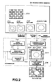
- Fig. 2 illustrates a sequence for producing and outputting a three-dimensional picture by the household game playing apparatus of Fig. 1, using two-dimensional picture data.
- the sequence depicted in Fig. 2 serves to produce a three-dimensional picture depicting a cylindrical object on checkerboard background pattern.
- the source video memory 95 stores a background picture 200 in the form of a checkerboard pattern and a sequence of rectangular pictures 201 through 204 each representing a cross section of the cylindrical object to be overlaid on the checkerboard background pattern at varying depths.
- the portions of the rectangular pictures 201 through 204 other than the cross sections of the cylinder contain data representing transparency.
- the picture data stored in the source video memory 95 is read-out in accordance with an address supplied from a readout table 101 of the video processor 96.
- the CPU 91 provides read-out address control data to the table 101 over the main bus 99 for indicating which address is to be output from the table 101.
- a sync generator 100 produces read-out timing signals which it supplies to the read-out address table 101 and which are matched with synchronization signals for the picture to be displayed so that the read-out addresses are supplied by the table 101 in the appropriate order and at the appropriate times for displaying the desired picture.
- the read-out picture data from the source video memory 95 are received by a superposition processor 103 which serves to superpose the picture data in the appropriate sequence in accordance with sequence data supplied from a priority table 102 under the control of signals supplied by the CPU 91 over the main bus 99.
- a superposition processor 103 which serves to superpose the picture data in the appropriate sequence in accordance with sequence data supplied from a priority table 102 under the control of signals supplied by the CPU 91 over the main bus 99.
- Each of the pictures 200 through 204 is assigned a sequential ranking beginning with a lowest rank for the background picture 200 and advancing to a highest ranking for the picture 204, so that the picture data as output by the superposition processor 103 represents a superposition of the pictures 200 through 204 in the appropriate order for displaying the cylindrical object on the checkerboard background.
- the data output by the superposition processor 103 is supplied to a transparent color processor 104 wherein the data of each of the data pictures 201 through 204 representing transparency are processed so that underlying data may be displayed. Once the data has thus been processed by the transparent color processor 104, the data is output thereby as picture data representing a three-dimensional picture VD0 as shown in Fig. 2.
- Fig. 3 is a block diagram of a proposed picture formulating apparatus which carries out a texture mapping function.
- a central processing unit (CPU) 301 is depicted comprising a microprocessor or the like coupled with a main bus 309.
- a main memory 302 for storing programs and data, a video memory 303 for storing texture source picturc data and a video memory 304 for storing display output data as formulated by the apparatus of Fig. 3, are coupled to the main bus 309.
- the CPU 301 reads out the texture source picture data from the video memory 303 with such modifications as are necessary in order to transform the texture data for mapping onto a display area of the video memory 303.
- the transformed texture data are written in the display area of the video memory 304 and later read therefrom and converted by a D/A converter 305 into analog signals which are output for displaying a picture.
- Figs. 4A through 4C depict a sequence of processing operations carried out by the picture formulating apparatus of Fig. 3.
- the main memory 302 stores a program for controlling the CPU 301 for specifying the particular texture source picture to be used at a given time as well as a read-out position therefor to which the CPU 301 responds by reading out the appropriate picture data from the preset locations in the video memory 303 and carries out the above-mentioned modifications thereon as designated by the program to produce the modified picture 312a as illustrated in Fig. 4B.
- a modified picture 312a is then written in a display area 321 of the video memory 304.
- the write addresses for the display area 321 are also designated by the program stored in the main memory 302.
- a sequence of such read out and modification operations as described above is carried out until the data of a complete picture 313 has been generated and stored in the display are 321 of the video memory 304.
- the picture data 313 is then read out from the video memory 304 in accordance with addresses determined as described above in synchronization with the video synchronization signals and converted to analog form by the D/A converter 305 to produce analog output picture signals.
- Fig. 5 provides a block diagram of a picture formulating apparatus which carries out a picture data converting function whereby color data is output from a conversion table in the form of a color lookup table in response to image data. This provides the ability to change the color of the displayed image without re-writing image data.
- the CPU 301, main memory 302, video memories 303 and 304 coupled by means of the main bus 309, as well as a D/A converter 305 are similar to the corresponding devices of the Fig. 3 apparatus and are not, therefore, further described herein.
- a conversion table memory 306 is also provided storing a conversion table such as a lookup table for converting output display picture data read out from the video memory 304. The converted data are output from the conversion table memory 306 to the D/A converter 305 for conversion to analog form and are supplied thereby to a video or image output.
- Figs. 6A through 6D a sequence of operations carried out by the apparatus of Fig. 5 in processing and outputting a picture is illustrated therein.
- the CPU 301 reads texture source data from the video memory 303 and modifies the same to store the modified data in appropriate locations of the video memory 304 to construct the picture 313 as depicted in Fig. 6A in accordance with the data conversion operations discussed above in connection with Figs. 3 and 4. That is, the picture data 313 of Fig. 6A corresponds to the like-referenced picture as depicted in Fig. 4C. However the picture data 313 stored in the video memory 304 is provided in an intermediate or temporary form which cannot be output as is thereby to produce a picture display.
- the picture data as store in the video memory 304 is read out from its display area 321, as represented by the illustration of Fig. 6B and used for addressing conversion table 314 in the conversion table memory 306 to output a color corresponding to each input address which, in turn, corresponds to a pixel of a picture to be output.
- the conversion table 314 serves to convert the address of virtual data supplied thereto from the video memory 304 into actual picture data, in accordance with a process represented schematically by Fig. 6C.
- the converted or actual picture data is output from the conversion table memory 306 to the D/A converter 305 for conversion thereby to analog picture data, as represented by Fig. 6D.
- the output picture data is not the same as that generated in the source video memory, but rather a three-dimensional picture is produced by changing read-out positions of the two-dimensional picture data stored in the source video memory and superposing the data of a number of pictures as read out. Consequently, the ability to express a three-dimensional picture generated in this manner is limited. For example, when processing a three-dimensional object picture for display by means of a household game playing apparatus on a screen, it may not be possible to correctly express the three-dimensional object picture in this way.
- the position of the object may not be changed correctly or the method of changing the three-dimensional picture may not be carried out in an appropriate manner.
- the position of the viewing direction according to which the three-dimensional object is depicted is thus limited, for example, so that a back side of the object picture cannot be depicted even though the position or the direction of view of the three-dimensional object picture has been changed so that the same should be visible. It may also happen that the screen display to the operator occurs discontinuously even when three-dimensionally continuous movement is depicted.
- the picture read-out control for the source video memory is complex and difficult to implement.
- a further difficulty is posed, for example, in the case of the apparatus of Fig. 3 for which it is necessary to provide a video memory 303 which is dedicated to storage of the source texture data, which thus hinders efforts to achieve size reduction in the apparatus as well as to hold down production costs therefor.
- a table memory 306 dedicated to storage of the conversion table as well as a CPU bus for accessing the table, which likewise hinders efforts to reduce the size of the apparatus as well as to minimize its production costs.
- a method for formulating image signals for producing a three-dimensional picture display comprises the steps of: reading out first coordinate data for apex points of a plurality of polygonal picture areas as units of a desired three-dimensional picture stored in a first memory; producing second coordinate data representing coordinates of the apex points on a predetermined screen based on the first coordinate data; producing color data for each of said apex points; producing color data and coordinate data of boundary points between the apex points using the color data and the coordinate data of each of said apex points on the predetermined screen; producing color data and coordinate data of intermediate points between said boundary points using the color data and the coordinate data of said boundary points; and storing the produced color data and the coordinate data of the intermediate points in a second memory to form image signals for producing a three-dimensional picture display.
- an apparatus for formulating image signals representing a three-dimensional picture for displaying said three-dimensional picture with the use of said image signals comprises: a first memory for storing first coordinate data of apex points of a plurality of polygonal areas as units of a desired three-dimensional picture; a geometry processor for converting the first coordinate data of the apex points of the polygonal areas stored in first memory to second coordinate data of a predetermined screen and for producing color data for each of said apex points; a raster processor for producing color data and coordinate data of boundary points between said apex points, based on the color data and the second coordinate data on the predetermined screen of the apex points as converted by said geometry processor, and for producing color data and coordinate data of intermediate points between said boundary points using the color data and coordinate data of the boundary points; and a second memory for storing the color data and the coordinate data of the intermediate points as produced by said raster processor, the color data of said intermediate points as stored representing said three-
- the coordinate data and color data of the apex points of the polygonal areas are stored in the first memory.
- two-dimensional texture data is modified and mapped onto three-dimensional picture data to be displayed.
- the coordinate data of the apex points of polygonal areas and texture coordinate data indicating coordinate positions of the two-dimensional texture data are stored in the first memory.
- the end positions of horizontally extending line segments slicing a polygonal area at a predetermined distance from one of the apex points thereof are used as the boundary points and color data of the intermediate points are produced based on such boundary points by interpolation.
- color information and “color data” include both color vectors for use in effecting a color display as well as luminance and gradation data for use in effecting a monochromatic display.
- a household game playing apparatus in which an object image for display as a three-dimensional picture is formulated, comprises : an external storage medium in which a game program and picture information employed in executing said game program are stored; operating means for processing the picture information of the game program stored in said external storage medium for producing display picture data representing movement of the object image; display means for displaying the display picture data; a first memory for storing first coordinate data of apex points of a plurality of polygonal areas in units of the object image included in said picture data; a geometry processor for converting the first coordinate data of the apex points of the polygonal areas stored in said first memory responsive to an input from said operating means for producing second coordinate data thereof on a predetermined screen and for producing color data for each of the apex points; a raster processor for producing color data and coordinate data of boundary points between said apex points, using the color data and coordinate data on said screen of said apex points as produced by said geometry processor, and
- the external storage medium for the household game playing machine is either a CD-ROM or a memory card.
- the game playing apparatus includes non-volatile storage means for storing the state of progress of the game on termination of a game program.
- data for the output picture to be displayed by the display means is formulated with the use of data written in a portion of a picture memory other than a portion thereof in which the output picture data is stored.
- the output picture data is formulated with the use of a conversion table and/or texture source data, and the memory locations in which the output picture data are stored in the picture memory are switched.
- a method for formulating picture data comprising the steps of: storing source data for formulating output picture data in a first region of a picture memory; processing the stored source data for producing the output picture data; and storing the output picture data in a second region of the picture memory other than the first region thereof.
- a picture formulating apparatus for formulating data of an output picture for output to a picture display device for displaying the output picture, comprises: a picture memory for storing the data of said output picture in a first storage area thereof and a processor for storing source data for formulating the output picture data in an area of said picture memory other than the first storage area for said output picture data and for producing the output picture data based on the source data.
- a household game playing apparatus for formulating data of an output picture to be output for display by a picture display device, comprises: a picture memory for storing data of said output picture in a first storage area thereof; and a processor for storing source data for formulating the output picture data in an area of said picture memory other than the first storage area for said output picture data and for producing the output picture data based on the source data.
- coordinate data of the apex points of polygonal areas stored in a first memory are converted for producing color data and further coordinate data on a predetermined screen, color data and coordinate data on the screen of boundary points between the apex points are produced using the color data and the coordinate data of the apex points on the screen, color data and coordinate data on the screen of intermediate points between the boundary points are produced using the color data and the coordinate data of the boundary points on the screen, and the color data of the intermediate points are written in a second memory for producing output data for use in displaying a three-dimensional picture.
- a method is employed using two-dimensional picture data, such as texture data, by slicing a polygonal area at a predetermined distance from one of the apex points thereof by means of a line segment having boundary points at either end, and producing color data of intermediate points of the line segment by interpolation and mapping the resulting color data of the intermediate points on three-dimensional picture data.
- a game program stored in the external storage medium (such as a CD-ROM or a memory card) is input to the apparatus, the game program including three-dimensional picture data for use in formulating a picture to be displayed.
- a three-dimensional object picture may be represented correctly. Also, since two-dimensional texture data is modified and mapped on a three-dimensional picture for display, and since texture coordinate data indicating coordinate points of the two-dimensional picture are employed in such mapping operation, the three-dimensional object may be represented with the use of such texture data correctly.
- a three-dimensional object picture may be formulated easily.
- the household game playing apparatus of the present invention in producing the display picture data representing movement of the object image, its position and orientation can be changed correctly and accurately by the operating means, and there is no limitation imposed on the direction and orientation of the object image as represented, so that, even if the picture from the viewpoint of the operator is changed continuously three-dimensionally, a picture may be displayed which is responsive to the continuous three-dimensional changes correctly and accurately.
- the data volume of the picture data necessary for representing the three-dimensional picture represents polygonal areas simply by their apex points, so that the game formulating time may be diminished, it becomes possible to improve game productivity and speed of execution of a computer formulated game.
- three-dimensional picture data is formulated horizontal line by horizontal line as the same as written in the video memory, so that the three-dimensional picture data thus written in the memory can be read during the usual scanning of video signals, the process of reading the picture data is made easy.
- a voluminous game program can be stored therein and read therefrom quickly.
- a three-dimensional picture may be produced correctly and accurately by means of an apparatus having an advantageously small size and low cost.
- a three-dimensional object picture may be represented accurately and correctly.
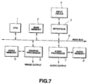
- a central processing unit such as a microprocessor, serves to fetch operating information from an input device 4, such as an input pad or a joystick, via an interface 3 and a main bus 9. Based on the operating information fetched from the device 4, the CPU 1 transmits a three-dimensional picture stored in a main memory 2 to a graphic processor 6 over the main bus 9.
- the graphic processor 6 serves to convert the data from the main memory 2 into picture data.
- a three-dimensional picture thus generated by the graphic processor 6 is stored in a video memory 5.
- the picture data stored in the memory 5 is read out in accordance with scanning by video signals for displaying a three-dimensional picture on a display device, not shown for purposes of simplicity and clarity.
- voice data which has been fetched by the CPU 1 from the main memory 2 and which is associated with the displayed three-dimensional picture is routed to an audio processor 7. Based on the received voice information, the audio processor 7 outputs appropriate voice data stored in an audio memory 8.
- a shading method for displaying a three-dimensional picture by shading an object is explained as a first embodiment of the present invention, while a texture mapping method also for displaying a three-dimensional picture, but by modification and mapping of further two-dimensional picture data will also be explained as a second embodiment of the present invention.
- An object coordinate system serves to represent the shape and size of a three-dimensional object itself.
- a world coordinate system represents the position of a three-dimensional object in a three-dimensional space.
- a screen coordinate system represent a three-dimensional object displayed on a two-dimensional screen.
- the object coordinate system and the screen coordinate system are principally used.
- a three-dimensional object may be represented according to the present invention by means of a plurality of polygonal areas, processing of data representing triangular areas will be described hereinbelow for purposes of simplicity and clarity.
- picture information such as color vectors and coordinates of the apex points of a triangle used for formulating a picture of a three-dimensional object are stored.
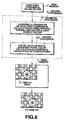
- the picture information stored in the memory 2 is read by the CPU 1 for supply to a geometry processor 61 of the graphic processor 6 as illustrated in Fig. 8.
- the coordinates of the apex points are converted to screen coordinates with the aid of read-out picture information, namely, a coordinate transformation matrix. That is, the coordinate transformation matrix is applied to the apex point coordinates and the X and Y coordinates thus obtained are divided by the Z coordinate thus obtained.
- color and luminance data for the apex points as displayed on the screen are calculated by obtaining the inner product of a normal line vector (a vector normal to the triangular area represented by the apex points) and a light source vector produced by light source data supplied by the CPU 1 which reads the same from the main memory 2.
- the result of the inner product multiplies color data specific to the apex point as described in greater detail below, for producing the color and luminance data thereof.
- the values of the color and luminance data of the apex points on the screen as thus obtained are routed to a raster processor 62 of the graphic processor 6, as depicted in Fig. 8, which produces output picture data for intermediate points of the triangle delimited by the three apex points, by an interpolation process using the coordinate values as well as the color and luminance data of the apex points.
- a picture VD1 of the three-dimensional object is obtained having pixels whose coordinate values represent position within a screen coordinate system which is stored in a display area 51 of the video memory 5 and output therefrom under the control of the graphic processor 6.
- the main memory 2 stores picture information such as coordinates of the apex points of a triangular area necessary for formulating a picture of a three-dimensional object.
- the main memory 2 stores texture coordinates indicating coordinate positions of texture data for mapping to another picture.
- the picture information is read by the CPU 1 of Fig. 7 from the main memory 2 thereof for routing to the geometry processor 61 of the graphic processor 6.
- the coordinates of the apex points are converted with the aid of the read-out picture information for calculating the coordinates of the apex points on the screen.
- Color and luminance data of the apex points on the screen are obtained by determining the inner product of the normal line vector to the triangular area and a light source vector produced from the light source data and the inner product thus produced multiplies color data specific to the apex point.
- the values of the color and luminance data of the apex points thus obtained are routed to the raster processor 62.
- the raster processor 62 also determines, by an interpolation process, luminance data for intermediate points in a triangular area delimited by three apex points in a texture area such that each apex point in the texture area corresponds to an apex point of the object area.
- the texture area is provided as an off screen area of the video memory 5 containing texture data to be mapped on the object.
- a picture VD2 as illustrated in Fig. 9 is formulated by mapping texture picture data on the various polygons of the object by accessing the luminance data from the texture picture 52 of Fig. 9 by means of appropriately produced coordinate values for matching the luminance data to pixels in the display area 51 of the video memory 5.
- a step SP1 of Fig. 10 information necessary for formulating the picture is accessed from a variety of picture information data stored in the main memory 2 of Fig. 8, such as coordinates V of the apex points of a small-size triangle represented in an object coordinate system, a coordinate conversion matrix R for converting the apex point coordinates from the object coordinate system into a world coordinate system, a parallel translation vector T for transforming the apex point coordinates in order to represent transnational movement of the object, a line-of-sight vector which serves to translate and rotate the entire three-dimensional image to present the image according to the position of the viewer and the direction in which the viewer is looking for representing the apex point coordinates according to the screen coordinate system, as well as a normal-line vector N and a color vector C.
- the foregoing data are read in sequence by the CPU 1 of Fig. 1 and routed to the graphic processor 6.
- a step SP2 of Fig. 10 the coordinate values of the apex points of the triangle and drawing colors therefor are produced using the data read out as described above.
- (X V , Y V , Z V ) represent the coordinate vectors of the apex points in the object coordinate system
- R is the coordinate conversion matrix for rotating the area
- (X T , Y T , Z T ) is the parallel translation vector.
- X X S x (h/Z S )
- Y Y S x (h/Z S )
- h the distance from the viewpoint of the operator to the display screen
- Z S represents the depth of the apex point from the screen after conversion in accordance with formula (1).
- the perspective conversion serves to modify the size of the object depending on the distance from the position of the operator in order to produce a scenographic or perspective sense or feeling.
- the normal-line vector N relative to the plane of the triangle is converted, with the use of the coordinate converting matrix R, into a normal line vector P in the screen coordinate system in accordance with the following formula (4):
- (X P , Y P , Z P ) (X N , Y N , Z N ) x R
- (X N , Y N , Z N ) is the normal-line vector N in the object coordinate system
- R is the coordinate conversion matrix mentioned above
- (X P , Y P , Z P ) is the normal-line vector P.
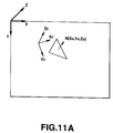
- the normal-line vector N as expressed in the object coordinate system having axes X0, Y0, and Z0 is illustrated therein relative to the triangular area it represents.
- the axes X, Y and Z of a screen coordinate system are overlaid for illustrating that is necessary to rotate the normal-line vector N by means of the coordinate conversion matrix R in accordance with formula (4) in order to represent the normal-line vector in accordance with the screen coordinate system and the vector P (X P , Y P , Z P ).
- a step SP3 of Fig. 10 it is determined whether the drawing colors and the coordinate values of all of the three apex points S0, S1, and S3 of the triangle have been found. If not, processing continues by returning to the step SP2 for finding the coordinate values and drawing colors of the next apex point. If, however, all such coordinate values and drawing colors have been found, processing continues in a step SP4 for finding the coordinate values of the all of the intermediate points of pixels within the triangle by means of the raster processor 62 as shown in Fig. 8 and the drawing colors thus obtained and represented by corresponding coordinate values are written in the video memory 5.
- the coordinate values and the drawing colors of the three apex points S0, S1 and S2 of the triangle are represented as follows: S0 (X0, Y0, R0, G0, B0) S1 (X1, Y1, R1, G1, B1) S2 (X2, Y2, R2, G2, B2) As shown in Fig. 11B, the triangle which is delimited by these three apex points is sliced in the horizontal direction by a line segment having the end points A and B corresponding with boundary points of the triangle.
- R P R A x (X B - X A - m) / (X B - X A ) + R B x m / (X B - X A )
- G P G A x (X B - X A - m) / (X B - X A ) + G B x m / (X B - X A )
- B P B A x (X B - X A - m) / (X B - X A ) + B B x m / (X B - X A )
- a step SP5 of Fig. 10 it is determined whether coordinate values for each of the triangles have been produced as well as the related drawing colors, and whether the drawing colors have been accordingly written in the display area 51 of the video memory 5. If such operations have been carried out for each triangle, the picture data thus stored in the display area 51 of Fig. 8 is output by the graphic processor 6 as the three-dimensional picture VD1 as illustrated in Fig. 8. If, however, such operations have not been carried out in their entirety, processing reverts to the step SP1 wherein the information necessary for producing the picture data for the next triangle is read from the main memory 2 of Fig. 8.
- Fig. 12 a sequence of operations which is carried out for producing and displaying a three-dimensional picture by the texture mapping method of the first embodiment of the present invention is illustrated therein.
- the CPU 1 of Fig. 7 reads the necessary information for producing the picture of a selected triangle from the main memory 2 thereof, namely, the coordinates of the its apex points in the object coordinate system, the coordinate conversion matrix from converting the apex point coordinates into the world coordinate system, the parallel translation vector T, the line-of-sight vector for representing the apex point coordinates in the world coordinate system according to the screen coordinate system, the normal-line vector N and apex point coordinates of a storage area for relevant texture data.
- the data is read in sequence by the CPU 1, it is routed thereby to the graphic processor 6.
- a step SP12 of Fig. 12 the coordinate values of the apex points of the triangle and luminance data therefor are produced using the information read in the step SP11.
- the three-dimensionally represented apex point coordinates are converted by means of the coordinate conversion matrix R and the parallel translation vector T, as described above, into the coordinates S in accordance with formula (1).
- the coordinates S are perspective-converted in accordance with the formulas (2) and (3) for conversion to screen coordinates (X, Y).
- a step SP13 of Fig. 12 it is then determined by the geometry processor 61 whether the luminance data and coordinate values of three apex points of the triangle have been found. If not, processing reverts to the step SP12 for finding the luminance data and coordinate values of the next apex point of the triangle. If, however, all such values have been found, processing continues in a step SP14 for finding all of the texture coordinate values of the intermediate points within the triangle from the texture picture data 52 as illustrated in Fig. 9, with the use of the raster processor 62. Then the luminance data represented by corresponding coordinate values of the display area 51 of Fig. 9 and associated with corresponding texture coordinate values are multiplied by picture data represented by the texture coordinates. The resulting values are written at locations of the display area 51 in accordance with corresponding coordinate values.
- the coordinate values of the three apex points T0, T1 and T2 of the triangle within the texture picture 52 which are to be mapped to the object picture are represented as T0 (U0, V0) T1 (U1, V1) T2 (U2, V2) and wherein coordinate values of a boundary point C between the points T0 and T1, a boundary point D between the points T0 and T2, as well as an intermediate point Q on a line segment defined by the points C and D, are represented as: C (U C , V C ) D (U D , V D ) Q (U Q , V Q)
- the coordinate values of the three apex points of the triangle within the object picture, as well as luminance data and texture coordinates of each point within the texture picture 52 may be represented as follows: S0 (X0, Y0, L0, U0, V0) S1 (X1, Y1, L1, U1, V1) S1 (X2, Y2, L2, U2, V2)
- the coordinate values and luminance data of the boundary point B are determined in accordance with formulas (27) through (29), while the coordinates of the boundary point D providing texture coordinates for the boundary point B are determined in accordance with formulas (30) and (31) as follows:
- X B X0 x (Y2 - Y0 - n) / (Y2 - Y0) + X2 x n / (Y2 - Y0)
- Y B Y0 + n
- L B L0 x (Y2 - Y0 - n) / (Y2 - Y0) + L2 x n / (Y2 - Y0)
- U D U0 x (Y2 - Y0 - n) / (Y2 - Y0) + U2 x n / (Y2 - Y2)
- V D V0 x (Y2 - Y0 - n) / (Y2 - Y0
- an intermediate point P along the line segment AB therein is shifted by a value m from the boundary point A towards the boundary point B.
- Coordinate values, luminance data and texture coordinates of the intermediate point P are produced by interpolation by means of the data of boundary points A and B. If the coordinates and luminance values of the intermediate point P are expressed as P (X P , Y P , L P ) the coordinates of an intermediate point Q as shown in Fig.
- Pixel data read from the texture picture 52 in accordance with the coordinates corresponding to each intermediate point P are then multiplied by the corresponding luminance data of that point.
- the resulting data is written at a corresponding location indicated by the coordinate values of the intermediate point P in the video memory 5.
- step SP15 of Fig. 12 it is determined whether the operations of finding the coordinate values and luminance data for each of the triangles, as well as whether the drawing colors therefor have been written in the display area 51 of the video memory 5 of Fig. 9 have been completed. If so, the picture data stored in the display area 51 of Fig. 9 is output by the graphic processor 6 as the three-dimensional picture VD2 of Fig. 9. If not, however, processing reverts to the step SP11 for finding the necessary data for the next triangle.
- the methods described above for formulating a three-dimensional picture may be applied selectively depending on the characteristics of the picture to be displayed. For example, if the shape of an object to be displayed as a three-dimensional picture is critical at a given point during a game, a picture preferably is drawn by the shading method according to the first embodiment. However, if the pattern of the object's surface is deemed to be more important, the picture is preferably produced in accordance with the texture mapping method of the second embodiment.
- the CPU 1 of Fig. 7 reads out texture source picture data from the video memory 5 in accordance with a program stored in the main memory 2 and modifies the source picture data, if necessary, for writing in the video memory 5.
- information pertinent to a picture to be output for display such as texture source data and conversion data (such as a color lookup table) is written in a portion of the memory other than the display area in which data of the picture to be output, that is, the display output picture data (picture to be displayed by a device such as a TV receiver, monitor receiver or CRT display) is stored.
- Fig. 15A schematically illustrates the memory space of the video memory 5 in an initial state wherein the memory space is divided into the above-mentioned display area 51 and a vacant area 53 outside the display area 51.
- a picture to be displayed on a CRT display device may include 400 vertical lines by 640 horizontal pixels or possibly 480 vertical lines by 720 horizontal pixels, whereas a typical video memory is provided with vertical and horizontal memory dimensions set equal to powers of 2.
- a memory having 512 vertical lines by 1024 horizontal words is required, so that redundant space is formed in both the vertical and horizontal directions of the memory space.
- a conversion table 55 such as a color lookup table is also written in the area 53.
- Fig. 16 provides a flow chart illustrating a typical processing sequence in accordance with this technique.
- the CPU 1 causes the texture source picture 54a through 54c to be written in the vacant area 53 of the video memory 55 before generating or formulating the display output picture data.
- the conversion table 55 such as a color lookup table, which serves to convert virtual picture data into actual picture data is also stored in the vacant area 53.
- the texture source picture data may be obtained, for example, by reading from an external storage device such as a disk or tape.
- a step SP 33 the CPU 1 executes a program stored in the main memory 2 for generation or formulation of a pre-set picture and depending on the results of such processing, reads data from the texture source pictures 54a through 54c in the area 53.
- the texture source picture data thus read out are modified in a step SP 34, if necessary, by reference to the conversion table 55, and in a step SP 35 the picture data for writing in the display are 51 are drawn or produced. That is, the data obtained directly from the texture source pictures are used as addresses to the conversion table 55 for converting the texture source picture data, as virtual picture data, into real picture data.
- the real picture data read from the conversion table 55 consequently, are written in the display area 51 of the video memory 55.
- a step SP 36 it is determined whether all picture drawing operations have been completed for all of the polygonal areas comprising the display output picture stored in the display area 51. If not, the operations of steps SP 33 through SP35 are repeated. If so, however, the picture drawing operations are terminated.
- FIG. 17A the state of the video memory 5 once the foregoing picture formulating operations have been completed is represented thereby, and with reference also to Fig. 17B, the display state of a CRT display device 57 employed to display a picture 56 thus formulated in the display area 51 of the memory 5 is provided.
- the picture data in the display area 51 is read out in accordance with video synchronization signals and output after conversion into analog form by a D/A converter (not shown for purposes of simplicity and clarity) for displaying the picture 56 on a screen surface 58 of the CRT display device 57 in Fig. 17B.
- the texture source pictures 54a through 54c and/or the conversion table 55 are stored in the vacant area 53 of the memory 5 outside the display area 51 thereof, neither a separate video memory 303 (as in the apparatus of Fig. 3) for storing the texture source pictures nor a separate conversion table memory 306 (as in the apparatus of Fig. 5) for storage of conversion tables is required, thus to permit a reduction in size of the apparatus and reduced production costs therefor.
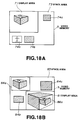
- the display area in the video memory 5 may be moved to permit the previously formulated display output picture itself to be used as a texture source picture, that is, as a reference picture for practicing a picture formulation technique in accordance with a further embodiment of the present invention. This embodiment is now explained in connection with Figs. 18A and 18B.
- a display area 71 of the video memory 5 is provided at a pre-set location therein and a number of texture source pictures 74a, 74b and 74c are stored in a vacant area 73 of the video memory 5 apart from the display area 71.
- N+1 the number of texture source pictures 74a, 74b and 74c are stored in a vacant area 73 of the video memory 5 apart from the display area 71.
- a display area 81 is provided in the video memory 5 at a location differing from the position of the display area 71 of Fig. 18A.
- a vacant area 83 apart from the display are 81, those portions of the picture previously written in the display area 71 which are required to formulate data for storage in the display area 18 to formulate a new picture are stored as a new texture source picture 84a as shown in Fig. 18B. That is, the display area 81 is selected so that it does not uverlap those portions of the display area of the Nth frame containing the new texture source picture 84a.
- texture source pictures 84b and 84c are also stored in the area 83. Then the texture source picture data 84a is read and modified in the same manner as other texture source data for writing in the display area 81 to formulate picture data 86a for the (N+1)th frame.
- a picture previously generated by the computer may be employed directly as texture source data for generating or formulating a picture.
- FIG. 19 a block diagram of an embodiment of a household game playing apparatus in accordance with one embodiment of the present invention is illustrated therein.
- a game program is stored in a CD-ROM 11, a read-only memory employing a compact disc as an external storage medium.
- a memory card 16 employing a non-volatile memory such as a flash memory, may be employed for the purpose of storing such a game program.
- a further alternative is the use of a ROM cartridge, not shown for purposes of simplicity and clarity.
- the game program may be received over an external network via a communication interface 12.
- the game program and accompanying three-dimensional picture information are entered from the CD-ROM 11 which is connected to an external storage interface 10, or in the alternative from the memory card 16 through the external storage interface 10 or from an external network connected to the communication interface 12, under the control of the CPU 1, such as a microprocessor.
- the game program and the three-dimensional picture information are stored over the main bus 9 and the main memory 2.
- Operating information is input from a controller 14, such as an input pad or a joystick when the same is fetched by the CPU 1 from the input interface 13 via the main bus 9.
- the three-dimensional picture information stored in the main memory 2 is converted by the graphic processor 6 for generating picture data for display.
- a three-dimensional picture is drawn in the video memory 5 by the graphic processor 6 with the aid of the picture data.
- the three-dimensional picture data thus drawn on the video memory 5 are read synchronously with the scanning of video signals for displaying the three-dimensional picture on a display device 15, such as a monitor.
- voice information associated with the displayed three-dimensional picture and included in the operating information fetched by the CPU 1 is routed to an audio processor 7. Based on such voice information, the audio processor 7 outputs appropriate voice data which is stored permanently in the audio memory 8.
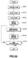
- a flow chart is provided therein for illustrating the operating sequence for initiating and carrying out a computer game by means of the household game playing apparatus in accordance with the present embodiment.
- a computerized driving game in which a car is driven on a road 22 with the object of avoiding a building 23 and given terrain 21 is implemented by the present embodiment utilizing the above-described texture mapping method.
- the external memory medium (such as the CD-ROM 11 or the memory card 16) is mounted via the external storage interface 10 on a main portion of the household game playing apparatus.
- the apparatus is connected via the communication interface 12 to the external network, as mentioned above.
- Necessary information such as the game program, functions, libraries and picture information is fetched to the main memory 2 from the external memory medium for storage or loading. Terrain data, building data, road data and texture data are loaded at this time as such picture information.
- the picture data are loaded directly from the external memory medium to the vacant area in the video memory 5 without the intermediate step of storing the same in the main memory 2.
- Step SP 22 Processing then continues in a step SP 22 in which one of a plurality of games stored in the external storage medium, or else provided by the external network, is selected for play and a mode of execution for the selected game is also selected. This operation is carried out in dependance on variables stored in the main memory 2 or based on the value of the register of the CPU 1.
- the game program is then executed at a step SP 23 under the control of the CPU 1 in order to start the computer game.
- An initial picture indicating that the game has started is formulated in a step SP 24 and displayed.
- a concrete example of such a picture is that illustrated in Fig. 21. This picture is formulated by carrying out the following sequence of operations.
- a remote scene is first prepared and displayed.
- a portion 20 representing the sky which is the farthest portion of the picture from the plane of the screen or the position of the viewer is initially formulated and displayed.
- Color data for the sky portion 20 is read from the main memory 2 by the CPU 1, that is, coordinate data of the four corners of the screen and color data for the sky portion 20 are output to the raster processor 62 within the graphic processor 6.
- relatively small polygonal areas also referred to as "polygons” are formulated in the color of the sky 20 for depiction by the display device 15.
- the terrain portion 21 is then displayed.
- the CPU 1 causes coordinates of the three-dimensional apex points of the polygons comprising the terrain 21 to be read from the main memory 2 for supply to the geometry processor 61.
- the processor 61 executes coordinate conversion and prospective conversion of the three-dimensional apex point coordinates to yield two-dimensional screen coordinate values, and also produces texture coordinate values associated with such two-dimensional coordinate values.
- the texture coordinate values thus produced are output to the raster processor 62 which reads out texture data corresponding to the input texture coordinate values from texture data stored in the video memory 5 in order to modify such texture data to conform to the polygons defined by the two-dimensional coordinate values to write the modified data in the video memory 5.
- the above operations are carried out for all of the polygons making up the terrain 21 and then the terrain 21 is displayed in its entirety by the display device 15.
- a three-dimensional picture may be produced and displayed employing the texture mapping method described hereinabove involving the production of texture coordinate values, as well as coordinate values and luminance data of the apex points of the polygons, and then writing texture data corresponding to the texture coordinate values as pixel data.
- texture data are used for formulating a picture of the road 22 and of the building 23, similar processing operations are carried out therefor as in the case of the terrain 21. If texture data are not used for formulating pictures of the road 22 and the building 23, color data for the polygons used to represent the road 22 and the building 23 are read from the main memory 2 and appropriate processing operations similar to those used for formulating the picture of the terrain 21 are carried out for formulating and displaying the road 22 and the building 23 by means of the display device 15.
- step SP 25 a standstill state for the game is set until a button or lever provided in a controller 14, such as a game controller or a game pad, are actuated by a game operator. If the controller 14 is actuated, data corresponding to the actuation is then fetched by the CPU 1 via the interface 13 and the game proceeds in accordance with the data thus obtained. Speed and direction information for the car to be driven as displayed are determined by data input with the use of the controller 14, and the position and orientation of the terrain 21, road 22, and building 23 as displayed is changed as required in accordance with the input data. Such changes are carried out by changing variables stored in the main memory 2 or values stored in a register of the CPU 1.
- a picture modified in accordance with data entered by means of a controller 14 as the computer game progresses is sequentially formulated in accordance with the above-described method and then displayed.
- the audio processor 7 fetches voice data matching the progress of the computer game from the audio memory 8 and outputs the fetched data.
- a step SP 27 it is determined depending on the progress of the game and based on the intent of the operator as expressed by operating the controller 14 or other appropriate input device, whether or not the game is to be terminated. If the game is not to be terminated, control reverts to the step SP 25 to await data representing the next operation to be entered from the controller 14. If the game is to be terminated, data representing the state of the game progress is stored in storage means, such as a non-volatile memory (not shown for purposes of simplicity and clarity) before terminating the game.
- storage means such as a non-volatile memory (not shown for purposes of simplicity and clarity) before terminating the game.
- the methods and apparatus of the present invention may be adapted for use not only in household game playing apparatus but in other types of game playing apparatus, such as apparatus used in arcades. Moreover, the methods and apparatus of the present invention may also be employed for implementing flight simulators and other training devices, as well as virtual reality systems. Various other applications for the present invention will be apparent to those of ordinary skill in the art based on the foregoing disclosure.
- the present invention provides: methods and apparatus for formulating three-dimensional picture data, and household game playing apparatus, wherein positions and orientations of an object as depicted thereby may be changed easily and quickly; and methods and apparatus, as well as household game playing apparatus, which employ conversion tables and/or texture source data and whose size and costs of production are advantageously reduced.
Abstract
Description
- The present invention relates to methods and apparatus for synthesizing three-dimensional picture signals and producing two-dimensional visual displays based on such signals.
- In general, TV receivers, receiver monitors and CRT displays used in conjunction with household game playing apparatus, personal computers and graphic computing devices provide two-dimensional displays. The signals or data are produced so that two-dimensional characters and the like are suitably arrayed and moved on a planar background with or without changes in shape. However, in such display techniques the ability to change either the background or the character, as well as the movement thereof, are limited so that the ambience of the game or other display cannot be enhanced.
- Methods have been adopted for formulating pseudo-three-dimensional images. In such techniques, plural pictures of a character to be displayed are stored, each picture depicting the character as viewed from a different direction. At a given time, one such picture is selected and displayed depending on the viewpoint adopted for the image being displayed. In another aspect of this technique, two-dimensional pictures are superposed along an image depth direction in order to display a pseudo-three-dimensional picture. In generating or formulating picture data, sometimes a texture mapping process is carried out whereby a surface texture or pattern, such as a ground pattern, is affixed to a selected face of a polyhedron forming an element of the image. A further technique employed involves converting picture color data by means of a so-called color pickup table in order to change the color of the displayed image.
- Fig. 1 provides a block diagram of a proposed household game playing apparatus. In the apparatus of Fig. 1, a central processing (CPU) 91 comprising a micro-processor fetches operating information from an
input device 94, such as an input pad or a joystick, via aninterface 93 and amain bus 99. As the operating information is fetched by theCPU 91, three-dimensional picture data stored in amain memory 92 are transferred by avideo processor 96 to asource video memory 95 for storage therein. - The
CPU 91 also transmits data to thevideo processor 96 indicating the sequence in which pictures represented inmemory 95 are to be displayed. Thevideo processor 96 reads out picture data from thesource video memory 95 in accordance with the data supplied by theCPU 91 in order to create a superposed picture display. - Simultaneously with the display of the picture, an
audio processor 97 outputs voice data from anaudio memory 98 which is based on voice information in the fetched operating information and which is coordinated with the picture that is being displayed. For example, if the picture being displayed depicts a car crashing, theaudio processor 97 outputs an appropriate crashing sound. - Fig. 2 illustrates a sequence for producing and outputting a three-dimensional picture by the household game playing apparatus of Fig. 1, using two-dimensional picture data. The sequence depicted in Fig. 2 serves to produce a three-dimensional picture depicting a cylindrical object on checkerboard background pattern.
- In Fig. 2, the
source video memory 95 stores abackground picture 200 in the form of a checkerboard pattern and a sequence ofrectangular pictures 201 through 204 each representing a cross section of the cylindrical object to be overlaid on the checkerboard background pattern at varying depths. The portions of therectangular pictures 201 through 204 other than the cross sections of the cylinder contain data representing transparency. - The picture data stored in the
source video memory 95 is read-out in accordance with an address supplied from a readout table 101 of thevideo processor 96. TheCPU 91 provides read-out address control data to the table 101 over themain bus 99 for indicating which address is to be output from the table 101. In addition, async generator 100 produces read-out timing signals which it supplies to the read-out address table 101 and which are matched with synchronization signals for the picture to be displayed so that the read-out addresses are supplied by the table 101 in the appropriate order and at the appropriate times for displaying the desired picture. - The read-out picture data from the
source video memory 95 are received by asuperposition processor 103 which serves to superpose the picture data in the appropriate sequence in accordance with sequence data supplied from a priority table 102 under the control of signals supplied by theCPU 91 over themain bus 99. Each of thepictures 200 through 204 is assigned a sequential ranking beginning with a lowest rank for thebackground picture 200 and advancing to a highest ranking for thepicture 204, so that the picture data as output by thesuperposition processor 103 represents a superposition of thepictures 200 through 204 in the appropriate order for displaying the cylindrical object on the checkerboard background. - The data output by the
superposition processor 103 is supplied to atransparent color processor 104 wherein the data of each of thedata pictures 201 through 204 representing transparency are processed so that underlying data may be displayed. Once the data has thus been processed by thetransparent color processor 104, the data is output thereby as picture data representing a three-dimensional picture VD₀ as shown in Fig. 2. - Fig. 3 is a block diagram of a proposed picture formulating apparatus which carries out a texture mapping function. In Fig. 3, a central processing unit (CPU) 301 is depicted comprising a microprocessor or the like coupled with a
main bus 309. Amain memory 302 for storing programs and data, avideo memory 303 for storing texture source picturc data and avideo memory 304 for storing display output data as formulated by the apparatus of Fig. 3, are coupled to themain bus 309. TheCPU 301 reads out the texture source picture data from thevideo memory 303 with such modifications as are necessary in order to transform the texture data for mapping onto a display area of thevideo memory 303. The transformed texture data are written in the display area of thevideo memory 304 and later read therefrom and converted by a D/A converter 305 into analog signals which are output for displaying a picture. - Figs. 4A through 4C depict a sequence of processing operations carried out by the picture formulating apparatus of Fig. 3. As shown in Fig. 4A, in the
video memory 303 several texture source pictures provide original data to be transformed as described above for texture mapping, such asource texture pictures main memory 302 stores a program for controlling theCPU 301 for specifying the particular texture source picture to be used at a given time as well as a read-out position therefor to which theCPU 301 responds by reading out the appropriate picture data from the preset locations in thevideo memory 303 and carries out the above-mentioned modifications thereon as designated by the program to produce the modified picture 312a as illustrated in Fig. 4B. A modified picture 312a is then written in a display area 321 of thevideo memory 304. The write addresses for the display area 321 are also designated by the program stored in themain memory 302. - A sequence of such read out and modification operations as described above is carried out until the data of a
complete picture 313 has been generated and stored in the display are 321 of thevideo memory 304. Thepicture data 313 is then read out from thevideo memory 304 in accordance with addresses determined as described above in synchronization with the video synchronization signals and converted to analog form by the D/A converter 305 to produce analog output picture signals. - Fig. 5 provides a block diagram of a picture formulating apparatus which carries out a picture data converting function whereby color data is output from a conversion table in the form of a color lookup table in response to image data. This provides the ability to change the color of the displayed image without re-writing image data. In the apparatus of Fig. 5, the
CPU 301,main memory 302,video memories main bus 309, as well as a D/A converter 305, are similar to the corresponding devices of the Fig. 3 apparatus and are not, therefore, further described herein. In the arrangement of Fig. 5, aconversion table memory 306 is also provided storing a conversion table such as a lookup table for converting output display picture data read out from thevideo memory 304. The converted data are output from theconversion table memory 306 to the D/A converter 305 for conversion to analog form and are supplied thereby to a video or image output. - With reference also to Figs. 6A through 6D, a sequence of operations carried out by the apparatus of Fig. 5 in processing and outputting a picture is illustrated therein. The
CPU 301 reads texture source data from thevideo memory 303 and modifies the same to store the modified data in appropriate locations of thevideo memory 304 to construct thepicture 313 as depicted in Fig. 6A in accordance with the data conversion operations discussed above in connection with Figs. 3 and 4. That is, thepicture data 313 of Fig. 6A corresponds to the like-referenced picture as depicted in Fig. 4C. However thepicture data 313 stored in thevideo memory 304 is provided in an intermediate or temporary form which cannot be output as is thereby to produce a picture display. - Rather, the picture data as store in the
video memory 304 is read out from its display area 321, as represented by the illustration of Fig. 6B and used for addressing conversion table 314 in theconversion table memory 306 to output a color corresponding to each input address which, in turn, corresponds to a pixel of a picture to be output. The conversion table 314 serves to convert the address of virtual data supplied thereto from thevideo memory 304 into actual picture data, in accordance with a process represented schematically by Fig. 6C. The converted or actual picture data is output from theconversion table memory 306 to the D/A converter 305 for conversion thereby to analog picture data, as represented by Fig. 6D. - It will seen from the foregoing that the output picture data is not the same as that generated in the source video memory, but rather a three-dimensional picture is produced by changing read-out positions of the two-dimensional picture data stored in the source video memory and superposing the data of a number of pictures as read out. Consequently, the ability to express a three-dimensional picture generated in this manner is limited. For example, when processing a three-dimensional object picture for display by means of a household game playing apparatus on a screen, it may not be possible to correctly express the three-dimensional object picture in this way. It may occur that, since the point of view of the operator with respect to the object picture changes after the three-dimensional object picture has been processed, either the position of the object may not be changed correctly or the method of changing the three-dimensional picture may not be carried out in an appropriate manner. Likewise, the position of the viewing direction according to which the three-dimensional object is depicted is thus limited, for example, so that a back side of the object picture cannot be depicted even though the position or the direction of view of the three-dimensional object picture has been changed so that the same should be visible. It may also happen that the screen display to the operator occurs discontinuously even when three-dimensionally continuous movement is depicted.
- Since multiple object pictures or picture data are stored in order to depict an object or other picture from various directions in order to represent a three-dimensional picture, the amount of data which must be stored for this purpose becomes voluminous. In addition, since the stored two-dimensional picture data are presented as three-dimensional picture data, substantial processing time is required for formulating each picture and game execution speed is consequently limited adversely.
- In addition, since the two-dimensional picture data stored in the source video memory must be modified in order to produce a three-dimensional picture, the picture read-out control for the source video memory is complex and difficult to implement.
- A further difficulty is posed, for example, in the case of the apparatus of Fig. 3 for which it is necessary to provide a
video memory 303 which is dedicated to storage of the source texture data, which thus hinders efforts to achieve size reduction in the apparatus as well as to hold down production costs therefor. In the case of the apparatus of Fig. 5, it is necessary to provide atable memory 306 dedicated to storage of the conversion table as well as a CPU bus for accessing the table, which likewise hinders efforts to reduce the size of the apparatus as well as to minimize its production costs. - In accordance with an aspect of the present invention, a method for formulating image signals for producing a three-dimensional picture display comprises the steps of: reading out first coordinate data for apex points of a plurality of polygonal picture areas as units of a desired three-dimensional picture stored in a first memory; producing second coordinate data representing coordinates of the apex points on a predetermined screen based on the first coordinate data; producing color data for each of said apex points; producing color data and coordinate data of boundary points between the apex points using the color data and the coordinate data of each of said apex points on the predetermined screen; producing color data and coordinate data of intermediate points between said boundary points using the color data and the coordinate data of said boundary points; and storing the produced color data and the coordinate data of the intermediate points in a second memory to form image signals for producing a three-dimensional picture display.
- In accordance with another aspect of the present invention, an apparatus for formulating image signals representing a three-dimensional picture for displaying said three-dimensional picture with the use of said image signals, comprises: a first memory for storing first coordinate data of apex points of a plurality of polygonal areas as units of a desired three-dimensional picture; a geometry processor for converting the first coordinate data of the apex points of the polygonal areas stored in first memory to second coordinate data of a predetermined screen and for producing color data for each of said apex points; a raster processor for producing color data and coordinate data of boundary points between said apex points, based on the color data and the second coordinate data on the predetermined screen of the apex points as converted by said geometry processor, and for producing color data and coordinate data of intermediate points between said boundary points using the color data and coordinate data of the boundary points; and a second memory for storing the color data and the coordinate data of the intermediate points as produced by said raster processor, the color data of said intermediate points as stored representing said three-dimensional picture.
- In certain embodiments, the coordinate data and color data of the apex points of the polygonal areas are stored in the first memory.
- In addition, in certain embodiments two-dimensional texture data is modified and mapped onto three-dimensional picture data to be displayed. In some embodiments, the coordinate data of the apex points of polygonal areas and texture coordinate data indicating coordinate positions of the two-dimensional texture data are stored in the first memory.
- In certain embodiments of the invention, the end positions of horizontally extending line segments slicing a polygonal area at a predetermined distance from one of the apex points thereof are used as the boundary points and color data of the intermediate points are produced based on such boundary points by interpolation.
- As used herein, the terms "color information" and "color data" include both color vectors for use in effecting a color display as well as luminance and gradation data for use in effecting a monochromatic display.
- In accordance with a further aspect of the present invention, a household game playing apparatus is provided in which an object image for display as a three-dimensional picture is formulated, comprises : an external storage medium in which a game program and picture information employed in executing said game program are stored; operating means for processing the picture information of the game program stored in said external storage medium for producing display picture data representing movement of the object image; display means for displaying the display picture data; a first memory for storing first coordinate data of apex points of a plurality of polygonal areas in units of the object image included in said picture data; a geometry processor for converting the first coordinate data of the apex points of the polygonal areas stored in said first memory responsive to an input from said operating means for producing second coordinate data thereof on a predetermined screen and for producing color data for each of the apex points; a raster processor for producing color data and coordinate data of boundary points between said apex points, using the color data and coordinate data on said screen of said apex points as produced by said geometry processor, and for producing color data and coordinate data of intermediate points between said boundary points, using the color data and coordinate data of said boundary points; and a second memory for storing the color data and the coordinate data of the intermediate points as produced by said raster processor for producing three-dimensional picture data of the object image.
- In certain embodiments, the external storage medium for the household game playing machine is either a CD-ROM or a memory card. In some embodiments, moreover, the game playing apparatus includes non-volatile storage means for storing the state of progress of the game on termination of a game program.
- In certain embodiments, data for the output picture to be displayed by the display means is formulated with the use of data written in a portion of a picture memory other than a portion thereof in which the output picture data is stored. In certain embodiments, the output picture data is formulated with the use of a conversion table and/or texture source data, and the memory locations in which the output picture data are stored in the picture memory are switched.
- In accordance with yet another aspect of the present invention a method for formulating picture data is provided, comprising the steps of: storing source data for formulating output picture data in a first region of a picture memory; processing the stored source data for producing the output picture data; and storing the output picture data in a second region of the picture memory other than the first region thereof.
- In accordance with a still further aspect of the present invention, a picture formulating apparatus for formulating data of an output picture for output to a picture display device for displaying the output picture, comprises: a picture memory for storing the data of said output picture in a first storage area thereof and a processor for storing source data for formulating the output picture data in an area of said picture memory other than the first storage area for said output picture data and for producing the output picture data based on the source data.
- In accordance with a still further aspect of the present invention, a household game playing apparatus for formulating data of an output picture to be output for display by a picture display device, comprises: a picture memory for storing data of said output picture in a first storage area thereof; and a processor for storing source data for formulating the output picture data in an area of said picture memory other than the first storage area for said output picture data and for producing the output picture data based on the source data.
- According to certain features of the present invention, coordinate data of the apex points of polygonal areas stored in a first memory are converted for producing color data and further coordinate data on a predetermined screen, color data and coordinate data on the screen of boundary points between the apex points are produced using the color data and the coordinate data of the apex points on the screen, color data and coordinate data on the screen of intermediate points between the boundary points are produced using the color data and the coordinate data of the boundary points on the screen, and the color data of the intermediate points are written in a second memory for producing output data for use in displaying a three-dimensional picture.
- In accordance with certain other features of the present invention, a method is employed using two-dimensional picture data, such as texture data, by slicing a polygonal area at a predetermined distance from one of the apex points thereof by means of a line segment having boundary points at either end, and producing color data of intermediate points of the line segment by interpolation and mapping the resulting color data of the intermediate points on three-dimensional picture data.
- In certain embodiments of the household game playing apparatus of the present invention, a game program stored in the external storage medium (such as a CD-ROM or a memory card) is input to the apparatus, the game program including three-dimensional picture data for use in formulating a picture to be displayed.
- Since color data and coordinate data of apex points of polygonal areas are stored in memory for formulating boundary point data and intermediate point data, a three-dimensional object picture may be represented correctly. Also, since two-dimensional texture data is modified and mapped on a three-dimensional picture for display, and since texture coordinate data indicating coordinate points of the two-dimensional picture are employed in such mapping operation, the three-dimensional object may be represented with the use of such texture data correctly.
- In those embodiments where a horizontally extending line segment is used to slice a polygonal area at a predetermined distance from one of the apex points thereof to defined boundary points and to derive color data for intermediate points along the segment by interpolation, a three-dimensional object picture may be formulated easily.
- In the case of the household game playing apparatus of the present invention, in producing the display picture data representing movement of the object image, its position and orientation can be changed correctly and accurately by the operating means, and there is no limitation imposed on the direction and orientation of the object image as represented, so that, even if the picture from the viewpoint of the operator is changed continuously three-dimensionally, a picture may be displayed which is responsive to the continuous three-dimensional changes correctly and accurately.
- Moreover, since the data volume of the picture data necessary for representing the three-dimensional picture represents polygonal areas simply by their apex points, so that the game formulating time may be diminished, it becomes possible to improve game productivity and speed of execution of a computer formulated game. In addition, in those embodiments where three-dimensional picture data is formulated horizontal line by horizontal line as the same as written in the video memory, so that the three-dimensional picture data thus written in the memory can be read during the usual scanning of video signals, the process of reading the picture data is made easy.
- In those embodiments which employ an external storage medium such as a CD-ROM or memory card, a voluminous game program can be stored therein and read therefrom quickly.
- In those embodiments which employ a non-volatile memory means in a game playing apparatus for storing game status data, the progress of a computer game up to the end of program execution can be recorded, so that the game can be re-started beginning from the point at which the program was terminated.
- By using portions of the picture memory other than those in which output display picture data are stored for storing picture data for use in formulating such output picture data, a three-dimensional picture may be produced correctly and accurately by means of an apparatus having an advantageously small size and low cost. In those embodiments in which a conversion table for a texture source picture data or other picture data is used for producing a display output picture, a three-dimensional object picture may be represented accurately and correctly.
- In those embodiments in which the addresses at which the output picture data is store are changed, it is possible to save and employ previously generated picture data to produce a new display output picture. In this manner, the new output picture can be represented correctly and accurately.
- Embodiments of the invention will now be described, by way of example only, with reference to the accompanying drawings in which:
- Fig. 1 is a block diagram of a proposed picture formulating apparatus;
- Fig. 2 illustrates a sequence of operations carried out by the apparatus of Fig. 1;
- Fig. 3 is a block diagram of a further picture formulating apparatus which carries out a texture data mapping function;
- Figs. 4A through 4C illustrate a sequence of operations carried out by the apparatus of Fig. 3;
- Fig. 5 is a block diagram of a further picture formulating apparatus which serves to convert picture data with the use of a conversion table;
- Fig. 6 illustrates a sequence of operations carried out by the apparatus of Fig. 5;
- Fig. 7 is a block diagram of a picture formulating apparatus in accordance with an embodiment of the present invention;
- Fig. 8 is a functional block diagram for use in explaining processing according to a first embodiment of a picture formulating method according to the present invention;
- Fig. 9 is a functional block diagram for use in illustrating processing in accordance with a second embodiment of a picture formulating method of the present invention;
- Fig. 10 is a flow chart for illustrating processing in accordance with the first embodiment of the picture formulating methods;
- Fig. 11A illustrates a process of converting a normal line vector in an object coordinate system to a normal line vector in a screen coordinate system;
- Fig. 11B illustrates coordinate values and drawing colors of a triangle as produced in accordance with the first embodiment of a picture formulating method;
- Fig. 12 is a flow chart for use in illustrating processing in accordance with the second embodiment of the picture formulating method;
- Fig. 13 illustrates texture coordinates used in carrying out the second embodiment of the picture formulating method;
- Fig. 14 illustrates coordinate values and luminance values of a triangular area as produced in accordance with the second embodiment of the picture formulating methods;
- Figs. 15A through 15C illustrate the utilization of memory space in a video memory used in carrying out the method in accordance with the second embodiment;
- Fig. 16 is a flow chart for use in illustrating processing according to the method of the second embodiment;
- Figs. 17A and 17B represent utilization of memory space and the display of an output picture, respectively, in accordance with a method employing a conversion table;
- Figs. 18A and 18B illustrate the usage of video memory area in accordance with a further embodiment of the present invention;
- Fig. 19 is a block diagram of a household game playing apparatus in accordance with another embodiment of the present invention;
- Fig. 20 is a flow chart for use in explaining the operation of the household game playing apparatus of Fig. 19;
- Fig. 21 is an exemplary display produced with the use of the household game playing apparatus of Fig. 19.
- With reference now to the drawings, and in particular to the embodiment of Fig. 7, a central processing unit (CPU 1), such as a microprocessor, serves to fetch operating information from an
input device 4, such as an input pad or a joystick, via aninterface 3 and amain bus 9. Based on the operating information fetched from thedevice 4, the CPU 1 transmits a three-dimensional picture stored in amain memory 2 to agraphic processor 6 over themain bus 9. Thegraphic processor 6 serves to convert the data from themain memory 2 into picture data. A three-dimensional picture thus generated by thegraphic processor 6 is stored in avideo memory 5. The picture data stored in thememory 5 is read out in accordance with scanning by video signals for displaying a three-dimensional picture on a display device, not shown for purposes of simplicity and clarity. - At the same time that the three-dimensional picture is being displayed as described above, voice data which has been fetched by the CPU 1 from the
main memory 2 and which is associated with the displayed three-dimensional picture is routed to anaudio processor 7. Based on the received voice information, theaudio processor 7 outputs appropriate voice data stored in anaudio memory 8. - A shading method for displaying a three-dimensional picture by shading an object is explained as a first embodiment of the present invention, while a texture mapping method also for displaying a three-dimensional picture, but by modification and mapping of further two-dimensional picture data will also be explained as a second embodiment of the present invention.
- Following are three-dimensional coordinate systems which will be employed in describing various features of the disclosed embodiments. An object coordinate system serves to represent the shape and size of a three-dimensional object itself. A world coordinate system represents the position of a three-dimensional object in a three-dimensional space. Finally, a screen coordinate system represent a three-dimensional object displayed on a two-dimensional screen. In order to simplify the explanation of the disclosed embodiments, the object coordinate system and the screen coordinate system are principally used. In addition, while a three-dimensional object may be represented according to the present invention by means of a plurality of polygonal areas, processing of data representing triangular areas will be described hereinbelow for purposes of simplicity and clarity.
- The shading method according to the first embodiment as mentioned above, will now be explained in connection with Fig. 8.
- In the
main memory 2 of the Fig. 7 apparatus, as depicted in Fig. 8, picture information, such as color vectors and coordinates of the apex points of a triangle used for formulating a picture of a three-dimensional object are stored. For the purpose of formulating such a picture, the picture information stored in thememory 2 is read by the CPU 1 for supply to ageometry processor 61 of thegraphic processor 6 as illustrated in Fig. 8. - In general, in the
graphic processor 61 the coordinates of the apex points are converted to screen coordinates with the aid of read-out picture information, namely, a coordinate transformation matrix. That is, the coordinate transformation matrix is applied to the apex point coordinates and the X and Y coordinates thus obtained are divided by the Z coordinate thus obtained. In addition, color and luminance data for the apex points as displayed on the screen are calculated by obtaining the inner product of a normal line vector (a vector normal to the triangular area represented by the apex points) and a light source vector produced by light source data supplied by the CPU 1 which reads the same from themain memory 2. The result of the inner product multiplies color data specific to the apex point as described in greater detail below, for producing the color and luminance data thereof. - The values of the color and luminance data of the apex points on the screen as thus obtained are routed to a
raster processor 62 of thegraphic processor 6, as depicted in Fig. 8, which produces output picture data for intermediate points of the triangle delimited by the three apex points, by an interpolation process using the coordinate values as well as the color and luminance data of the apex points. In this manner, a picture VD₁ of the three-dimensional object is obtained having pixels whose coordinate values represent position within a screen coordinate system which is stored in adisplay area 51 of thevideo memory 5 and output therefrom under the control of thegraphic processor 6. - As depicted in Fig. 8, the
main memory 2 stores picture information such as coordinates of the apex points of a triangular area necessary for formulating a picture of a three-dimensional object. In addition, themain memory 2 stores texture coordinates indicating coordinate positions of texture data for mapping to another picture. In the texture mapping method in accordance with the second embodiment of the present invention, the picture information is read by the CPU 1 of Fig. 7 from themain memory 2 thereof for routing to thegeometry processor 61 of thegraphic processor 6. - In the
geometry processor 61 the coordinates of the apex points are converted with the aid of the read-out picture information for calculating the coordinates of the apex points on the screen. Color and luminance data of the apex points on the screen are obtained by determining the inner product of the normal line vector to the triangular area and a light source vector produced from the light source data and the inner product thus produced multiplies color data specific to the apex point. The values of the color and luminance data of the apex points thus obtained are routed to theraster processor 62. Theraster processor 62 also determines, by an interpolation process, luminance data for intermediate points in a triangular area delimited by three apex points in a texture area such that each apex point in the texture area corresponds to an apex point of the object area. The texture area is provided as an off screen area of thevideo memory 5 containing texture data to be mapped on the object. In this manner, a picture VD₂ as illustrated in Fig. 9, is formulated by mapping texture picture data on the various polygons of the object by accessing the luminance data from thetexture picture 52 of Fig. 9 by means of appropriately produced coordinate values for matching the luminance data to pixels in thedisplay area 51 of thevideo memory 5. Once the picture data has been thus formulated and stored in thedisplay area 51, it is then output under the control of thegraphic processor 6. - A sequence of operations carried out by the apparatus of Fig. 7 for producing and displaying a three-dimensional picture in accordance with the shading method of the first embodiment is illustrated in the flow chart of Fig. 10.
- In a step SP1 of Fig. 10, information necessary for formulating the picture is accessed from a variety of picture information data stored in the
main memory 2 of Fig. 8, such as coordinates V of the apex points of a small-size triangle represented in an object coordinate system, a coordinate conversion matrix R for converting the apex point coordinates from the object coordinate system into a world coordinate system, a parallel translation vector T for transforming the apex point coordinates in order to represent transnational movement of the object, a line-of-sight vector which serves to translate and rotate the entire three-dimensional image to present the image according to the position of the viewer and the direction in which the viewer is looking for representing the apex point coordinates according to the screen coordinate system, as well as a normal-line vector N and a color vector C. The foregoing data, as required, are read in sequence by the CPU 1 of Fig. 1 and routed to thegraphic processor 6. - In a step SP2 of Fig. 10, the coordinate values of the apex points of the triangle and drawing colors therefor are produced using the data read out as described above. First, in the geometry processor 61 (Fig. 8) the three-dimensional coordinates of each apex point are converted by means of the coordinate conversion matrix R (for rotating the triangular area) and the parallel translation vector T (for translating the same) to produce corresponding three-dimensional coordinate vectors V in accordance with the following formula (1):

wherein (XS, YS, ZS) represents coordinates of the apex points S₀, S₂, and S₁ as illustrated in Fig. 11B, (XV, YV, ZV) represent the coordinate vectors of the apex points in the object coordinate system, R is the coordinate conversion matrix for rotating the area, and (XT, YT, ZT) is the parallel translation vector. - The coordinates XS and YS are then subjected to perspective conversion in accordance with the following formulas (2) and (3):


wherein h represents the distance from the viewpoint of the operator to the display screen and ZS represents the depth of the apex point from the screen after conversion in accordance with formula (1). The perspective conversion serves to modify the size of the object depending on the distance from the position of the operator in order to produce a scenographic or perspective sense or feeling. - The normal-line vector N relative to the plane of the triangle is converted, with the use of the coordinate converting matrix R, into a normal line vector P in the screen coordinate system in accordance with the following formula (4):

wherein (XN, YN, ZN) is the normal-line vector N in the object coordinate system, R is the coordinate conversion matrix mentioned above and (XP, YP, ZP) is the normal-line vector P. With reference also to Fig. 11A, the normal-line vector N as expressed in the object coordinate system having axes X₀, Y₀, and Z₀ is illustrated therein relative to the triangular area it represents. As also shown in Fig. 11A, the axes X, Y and Z of a screen coordinate system are overlaid for illustrating that is necessary to rotate the normal-line vector N by means of the coordinate conversion matrix R in accordance with formula (4) in order to represent the normal-line vector in accordance with the screen coordinate system and the vector P (XP, YP, ZP). - Then the inner product of the light source vector L and the normal-line vector P which was obtained by means of the formula (4) is then produced as follows according to formula (5A):

A drawing color D for each apex point is then obtained by means of the formula (5B):
wherein (RC, GC, BC) is a color vector of the relevant apex point and (RD, GD, BD) is the drawing color D for the apex point. - In a step SP3 of Fig. 10, it is determined whether the drawing colors and the coordinate values of all of the three apex points S₀, S₁, and S₃ of the triangle have been found. If not, processing continues by returning to the step SP2 for finding the coordinate values and drawing colors of the next apex point. If, however, all such coordinate values and drawing colors have been found, processing continues in a step SP4 for finding the coordinate values of the all of the intermediate points of pixels within the triangle by means of the
raster processor 62 as shown in Fig. 8 and the drawing colors thus obtained and represented by corresponding coordinate values are written in thevideo memory 5. - With reference also to Fig. 11B, the coordinate values and the drawing colors of the three apex points S₀, S₁ and S₂ of the triangle are represented as follows:
S₀ (X₀, Y₀, R₀, G₀, B₀)
S₁ (X₁, Y₁, R₁, G₁, B₁)
S₂ (X₂, Y₂, R₂, G₂, B₂)
As shown in Fig. 11B, the triangle which is delimited by these three apex points is sliced in the horizontal direction by a line segment having the end points A and B corresponding with boundary points of the triangle. The coordinate points and drawing colors for each of a plurality of boundary points A and B for each of n raster lines are found by interpolation as follows: if the coordinate values of the boundary points A and B are given by
A (XA, YA, RA, GA, BA)
B (XB, YB, RB, GB, BB)
the coordinate values and the drawing colors of the boundary point A is determined by the following formulas (6) through (10):


- The coordinate values and the drawing colors for the point B are then determined in accordance with the following formulas (11) through (15):


Then coordinate values and drawings colors of intermediate points P along the segment from the point A to the point B are found by interpolation from the corresponding values of the boundary points A and B and are represented by the following expression:
P (XP, YP, RP, GP, BP)
the values of which are produced by means of the following formulas (16) through (20).


- Then the pixel values (RP, GP, BP) of each intermediate point P are then written in the
display area 51 of thevideo memory 5 as shown in Fig. 8 according to the coordinate values of each intermediate point P. - In a step SP5 of Fig. 10, it is determined whether coordinate values for each of the triangles have been produced as well as the related drawing colors, and whether the drawing colors have been accordingly written in the
display area 51 of thevideo memory 5. If such operations have been carried out for each triangle, the picture data thus stored in thedisplay area 51 of Fig. 8 is output by thegraphic processor 6 as the three-dimensional picture VD₁ as illustrated in Fig. 8. If, however, such operations have not been carried out in their entirety, processing reverts to the step SP1 wherein the information necessary for producing the picture data for the next triangle is read from themain memory 2 of Fig. 8. - Referring now to Fig. 12, a sequence of operations which is carried out for producing and displaying a three-dimensional picture by the texture mapping method of the first embodiment of the present invention is illustrated therein.
- In a step SP11 of Fig. 12, the CPU 1 of Fig. 7 reads the necessary information for producing the picture of a selected triangle from the
main memory 2 thereof, namely, the coordinates of the its apex points in the object coordinate system, the coordinate conversion matrix from converting the apex point coordinates into the world coordinate system, the parallel translation vector T, the line-of-sight vector for representing the apex point coordinates in the world coordinate system according to the screen coordinate system, the normal-line vector N and apex point coordinates of a storage area for relevant texture data. As the data is read in sequence by the CPU 1, it is routed thereby to thegraphic processor 6. - In a step SP12 of Fig. 12, the coordinate values of the apex points of the triangle and luminance data therefor are produced using the information read in the step SP11. First, in the geometry processor 61 (Fig. 8), the three-dimensionally represented apex point coordinates are converted by means of the coordinate conversion matrix R and the parallel translation vector T, as described above, into the coordinates S in accordance with formula (1). Thereafter, the coordinates S are perspective-converted in accordance with the formulas (2) and (3) for conversion to screen coordinates (X, Y).
- Also, the normal-line vector N of the triangle is converted into the normal-line vector P in accordance with formula (4) above by means of the coordinate conversion matrix R. Then the inner produce of the normal-line vector P and the light source vector L is determined in accordance with formula (5A) to yield a lighting quantity lQ, as represented by formula (21).

- In a step SP13 of Fig. 12, it is then determined by the
geometry processor 61 whether the luminance data and coordinate values of three apex points of the triangle have been found. If not, processing reverts to the step SP12 for finding the luminance data and coordinate values of the next apex point of the triangle. If, however, all such values have been found, processing continues in a step SP14 for finding all of the texture coordinate values of the intermediate points within the triangle from thetexture picture data 52 as illustrated in Fig. 9, with the use of theraster processor 62. Then the luminance data represented by corresponding coordinate values of thedisplay area 51 of Fig. 9 and associated with corresponding texture coordinate values are multiplied by picture data represented by the texture coordinates. The resulting values are written at locations of thedisplay area 51 in accordance with corresponding coordinate values. - With reference also to Fig. 13, the coordinate values of the three apex points T₀, T₁ and T₂ of the triangle within the
texture picture 52 which are to be mapped to the object picture are represented as
T₀ (U₀, V₀)
T₁ (U₁, V₁)
T₂ (U₂, V₂)
and wherein coordinate values of a boundary point C between the points T₀ and T₁, a boundary point D between the points T₀ and T₂, as well as an intermediate point Q on a line segment defined by the points C and D, are represented as:
C (UC, VC)
D (UD, VD)
Q (UQ, VQ) - Since the three apex points of the triangle within the
texture picture 52 are each associated with a corresponding one of the three apex points of the triangle within the object picture, the coordinate values of the three apex points of the triangle within the object picture, as well as luminance data and texture coordinates of each point within thetexture picture 52 may be represented as follows:
S₀ (X₀, Y₀, L₀, U₀, V₀)
S₁ (X₁, Y₁, L₁, U₁, V₁)
S₁ (X₂, Y₂, L₂, U₂, V₂) - The triangle delimited by these three apex points S₀, S₁ and S₂ is sliced in the horizontal direction, as illustrated in Fig. 14, by a line segment defined by boundary points A and B as shown therein. The coordinate values and luminance data of the boundary points A and B for each of n raster lines are found by interpolation and are expressed as follows:
A (XA, YA, LA)
B (XB, YB, LB)
The coordinate values and luminance data of the boundary point A are determined in accordance with formulas (22) through (24) below, while the coordinates of the boundary point C providing texture coordinates for the boundary point A are determined in accordance with formulas (25) and (26) below:


- The coordinate values and luminance data of the boundary point B are determined in accordance with formulas (27) through (29), while the coordinates of the boundary point D providing texture coordinates for the boundary point B are determined in accordance with formulas (30) and (31) as follows:


- With reference again to Fig. 14, an intermediate point P along the line segment AB therein is shifted by a value m from the boundary point A towards the boundary point B. Coordinate values, luminance data and texture coordinates of the intermediate point P are produced by interpolation by means of the data of boundary points A and B. If the coordinates and luminance values of the intermediate point P are expressed as P (XP, YP, LP) the coordinates of an intermediate point Q as shown in Fig. 13 within the texture data and corresponding to the intermediate point P and providing its texture coordinates, are determined in accordance with the formulas (32) through (36) below:


The formulas (35) and (36) serve to relate the texture coordinates UQ and VQ to the point P in order to access corresponding pixel data from thepicture 52. - Pixel data read from the
texture picture 52 in accordance with the coordinates corresponding to each intermediate point P, are then multiplied by the corresponding luminance data of that point. The resulting data is written at a corresponding location indicated by the coordinate values of the intermediate point P in thevideo memory 5. - Thereafter, in a step SP15 of Fig. 12, it is determined whether the operations of finding the coordinate values and luminance data for each of the triangles, as well as whether the drawing colors therefor have been written in the
display area 51 of thevideo memory 5 of Fig. 9 have been completed. If so, the picture data stored in thedisplay area 51 of Fig. 9 is output by thegraphic processor 6 as the three-dimensional picture VD₂ of Fig. 9. If not, however, processing reverts to the step SP11 for finding the necessary data for the next triangle. - The methods described above for formulating a three-dimensional picture may be applied selectively depending on the characteristics of the picture to be displayed. For example, if the shape of an object to be displayed as a three-dimensional picture is critical at a given point during a game, a picture preferably is drawn by the shading method according to the first embodiment. However, if the pattern of the object's surface is deemed to be more important, the picture is preferably produced in accordance with the texture mapping method of the second embodiment.
- A technique for formulating a picture using the texture mapping function described above and a picture data converting function by means of a conversion table utilizing the picture formulating apparatus of Fig. 7 will now be explained.
- The CPU 1 of Fig. 7 reads out texture source picture data from the
video memory 5 in accordance with a program stored in themain memory 2 and modifies the source picture data, if necessary, for writing in thevideo memory 5. Within thevideo memory 5, information pertinent to a picture to be output for display, such as texture source data and conversion data (such as a color lookup table) is written in a portion of the memory other than the display area in which data of the picture to be output, that is, the display output picture data (picture to be displayed by a device such as a TV receiver, monitor receiver or CRT display) is stored. - Fig. 15A schematically illustrates the memory space of the
video memory 5 in an initial state wherein the memory space is divided into the above-mentioneddisplay area 51 and avacant area 53 outside thedisplay area 51. For example, a picture to be displayed on a CRT display device may include 400 vertical lines by 640 horizontal pixels or possibly 480 vertical lines by 720 horizontal pixels, whereas a typical video memory is provided with vertical and horizontal memory dimensions set equal to powers of 2. In either exemplary memory application, therefore, a memory having 512 vertical lines by 1024 horizontal words is required, so that redundant space is formed in both the vertical and horizontal directions of the memory space. With reference to Fig. 15B, in thevacant area 53several pictures area 53. - Fig. 16 provides a flow chart illustrating a typical processing sequence in accordance with this technique. In a step SP 31 of Fig. 16, the CPU 1 causes the
texture source picture 54a through 54c to be written in thevacant area 53 of thevideo memory 55 before generating or formulating the display output picture data. At astep SP 32, the conversion table 55 such as a color lookup table, which serves to convert virtual picture data into actual picture data is also stored in thevacant area 53. The texture source picture data may be obtained, for example, by reading from an external storage device such as a disk or tape. - In a step SP 33, the CPU 1 executes a program stored in the
main memory 2 for generation or formulation of a pre-set picture and depending on the results of such processing, reads data from the texture source pictures 54a through 54c in thearea 53. The texture source picture data thus read out are modified in a step SP 34, if necessary, by reference to the conversion table 55, and in a step SP 35 the picture data for writing in the display are 51 are drawn or produced. That is, the data obtained directly from the texture source pictures are used as addresses to the conversion table 55 for converting the texture source picture data, as virtual picture data, into real picture data. The real picture data read from the conversion table 55 consequently, are written in thedisplay area 51 of thevideo memory 55. - In a step SP 36, it is determined whether all picture drawing operations have been completed for all of the polygonal areas comprising the display output picture stored in the
display area 51. If not, the operations of steps SP 33 through SP35 are repeated. If so, however, the picture drawing operations are terminated. - With reference also to Fig. 17A, the state of the
video memory 5 once the foregoing picture formulating operations have been completed is represented thereby, and with reference also to Fig. 17B, the display state of aCRT display device 57 employed to display apicture 56 thus formulated in thedisplay area 51 of thememory 5 is provided. With reference to Fig. 17A, the picture data in thedisplay area 51 is read out in accordance with video synchronization signals and output after conversion into analog form by a D/A converter (not shown for purposes of simplicity and clarity) for displaying thepicture 56 on ascreen surface 58 of theCRT display device 57 in Fig. 17B. - In the present embodiment, since the texture source pictures 54a through 54c and/or the conversion table 55 (such as a color lookup table) are stored in the
vacant area 53 of thememory 5 outside thedisplay area 51 thereof, neither a separate video memory 303 (as in the apparatus of Fig. 3) for storing the texture source pictures nor a separate conversion table memory 306 (as in the apparatus of Fig. 5) for storage of conversion tables is required, thus to permit a reduction in size of the apparatus and reduced production costs therefor. Moreover, since virtual data obtained directly from the texture source pictures 54a through 54c in thevacant area 53 of thememory 5 are converted by reference to the conversion table 55 into real picture data which is then written in thedisplay area 51, there is no necessity to provide a separate bus for accessing a conversion table in a separate memory (such as thememory 306 of Fig. 5) which assists further in reducing apparatus size and production costs. - Moreover, the display area in the
video memory 5 may be moved to permit the previously formulated display output picture itself to be used as a texture source picture, that is, as a reference picture for practicing a picture formulation technique in accordance with a further embodiment of the present invention. This embodiment is now explained in connection with Figs. 18A and 18B. - With reference first to Fig. 18A, the contents of the
video memory 5 during an arbitrary Nth frame are illustrated thereby. During the Nth frame, a display area 71 of thevideo memory 5 is provided at a pre-set location therein and a number oftexture source pictures vacant area 73 of thevideo memory 5 apart from the display area 71. As explained below, during a following (N+1)th frame, at least a portion of the picture formulated during the Nth frame and written in the display area 71 is used directly as texture source data for producing a further display output picture. - With reference now to Fig. 18B the contents of the
video memory 5 during the next (N+1)th frame are illustrated therein. At that time, a display area 81 is provided in thevideo memory 5 at a location differing from the position of the display area 71 of Fig. 18A. In avacant area 83 apart from the display are 81, those portions of the picture previously written in the display area 71 which are required to formulate data for storage in the display area 18 to formulate a new picture are stored as a newtexture source picture 84a as shown in Fig. 18B. That is, the display area 81 is selected so that it does not uverlap those portions of the display area of the Nth frame containing the newtexture source picture 84a. In addition, a number of texture source pictures 84b and 84c as required are also stored in thearea 83. Then the texturesource picture data 84a is read and modified in the same manner as other texture source data for writing in the display area 81 to formulatepicture data 86a for the (N+1)th frame. - Accordingly, with the use of this method a picture previously generated by the computer may be employed directly as texture source data for generating or formulating a picture.
- A game playing apparatus in accordance with an aspect of the present invention, employing features of the above-described picture formulating methods and apparatus, will now be explained.
- With reference to Fig. 19, a block diagram of an embodiment of a household game playing apparatus in accordance with one embodiment of the present invention is illustrated therein. In the embodiment of Fig. 19, a game program is stored in a CD-ROM 11, a read-only memory employing a compact disc as an external storage medium. In the alternative, a
memory card 16 employing a non-volatile memory such as a flash memory, may be employed for the purpose of storing such a game program. A further alternative is the use of a ROM cartridge, not shown for purposes of simplicity and clarity. As yet another alternative, the game program may be received over an external network via acommunication interface 12. - The game program and accompanying three-dimensional picture information are entered from the CD-ROM 11 which is connected to an
external storage interface 10, or in the alternative from thememory card 16 through theexternal storage interface 10 or from an external network connected to thecommunication interface 12, under the control of the CPU 1, such as a microprocessor. The game program and the three-dimensional picture information are stored over themain bus 9 and themain memory 2. Operating information is input from acontroller 14, such as an input pad or a joystick when the same is fetched by the CPU 1 from theinput interface 13 via themain bus 9. Based on the operating information thus obtained by the CPU 1, the three-dimensional picture information stored in themain memory 2 is converted by thegraphic processor 6 for generating picture data for display. A three-dimensional picture is drawn in thevideo memory 5 by thegraphic processor 6 with the aid of the picture data. The three-dimensional picture data thus drawn on thevideo memory 5 are read synchronously with the scanning of video signals for displaying the three-dimensional picture on adisplay device 15, such as a monitor. - Simultaneously as the three-dimensional picture is thus displayed, voice information associated with the displayed three-dimensional picture and included in the operating information fetched by the CPU 1 is routed to an
audio processor 7. Based on such voice information, theaudio processor 7 outputs appropriate voice data which is stored permanently in theaudio memory 8. - With reference also to Fig. 20, a flow chart is provided therein for illustrating the operating sequence for initiating and carrying out a computer game by means of the household game playing apparatus in accordance with the present embodiment. For example, and with reference also to Fig. 21, a computerized driving game in which a car is driven on a
road 22 with the object of avoiding abuilding 23 and given terrain 21 is implemented by the present embodiment utilizing the above-described texture mapping method. - With reference to Fig. 20 in a step SP 21, the external memory medium (such as the CD-ROM 11 or the memory card 16) is mounted via the
external storage interface 10 on a main portion of the household game playing apparatus. In the alternative, the apparatus is connected via thecommunication interface 12 to the external network, as mentioned above. Necessary information, such as the game program, functions, libraries and picture information is fetched to themain memory 2 from the external memory medium for storage or loading. Terrain data, building data, road data and texture data are loaded at this time as such picture information. In addition, the picture data are loaded directly from the external memory medium to the vacant area in thevideo memory 5 without the intermediate step of storing the same in themain memory 2. - Processing then continues in a
step SP 22 in which one of a plurality of games stored in the external storage medium, or else provided by the external network, is selected for play and a mode of execution for the selected game is also selected. This operation is carried out in dependance on variables stored in themain memory 2 or based on the value of the register of the CPU 1. - The game program is then executed at a
step SP 23 under the control of the CPU 1 in order to start the computer game. - An initial picture indicating that the game has started is formulated in a step SP 24 and displayed. A concrete example of such a picture is that illustrated in Fig. 21. This picture is formulated by carrying out the following sequence of operations.
- In formulating the picture of Fig. 21, a remote scene is first prepared and displayed. For example, a
portion 20 representing the sky which is the farthest portion of the picture from the plane of the screen or the position of the viewer is initially formulated and displayed. Color data for thesky portion 20 is read from themain memory 2 by the CPU 1, that is, coordinate data of the four corners of the screen and color data for thesky portion 20 are output to theraster processor 62 within thegraphic processor 6. In theraster processor 62, relatively small polygonal areas (also referred to as "polygons") are formulated in the color of thesky 20 for depiction by thedisplay device 15. - The terrain portion 21 is then displayed. The CPU 1 causes coordinates of the three-dimensional apex points of the polygons comprising the terrain 21 to be read from the
main memory 2 for supply to thegeometry processor 61. Theprocessor 61 executes coordinate conversion and prospective conversion of the three-dimensional apex point coordinates to yield two-dimensional screen coordinate values, and also produces texture coordinate values associated with such two-dimensional coordinate values. The texture coordinate values thus produced are output to theraster processor 62 which reads out texture data corresponding to the input texture coordinate values from texture data stored in thevideo memory 5 in order to modify such texture data to conform to the polygons defined by the two-dimensional coordinate values to write the modified data in thevideo memory 5. The above operations are carried out for all of the polygons making up the terrain 21 and then the terrain 21 is displayed in its entirety by thedisplay device 15. - Accordingly, as explained with reference to Figs. 9 and 12 through 18, a three-dimensional picture may be produced and displayed employing the texture mapping method described hereinabove involving the production of texture coordinate values, as well as coordinate values and luminance data of the apex points of the polygons, and then writing texture data corresponding to the texture coordinate values as pixel data.
- In addition, if texture data are used for formulating a picture of the
road 22 and of thebuilding 23, similar processing operations are carried out therefor as in the case of the terrain 21. If texture data are not used for formulating pictures of theroad 22 and thebuilding 23, color data for the polygons used to represent theroad 22 and thebuilding 23 are read from themain memory 2 and appropriate processing operations similar to those used for formulating the picture of the terrain 21 are carried out for formulating and displaying theroad 22 and thebuilding 23 by means of thedisplay device 15. - Once the picture has been displayed in the foregoing manner, processing continues in a step SP 25 where a standstill state for the game is set until a button or lever provided in a
controller 14, such as a game controller or a game pad, are actuated by a game operator. If thecontroller 14 is actuated, data corresponding to the actuation is then fetched by the CPU 1 via theinterface 13 and the game proceeds in accordance with the data thus obtained. Speed and direction information for the car to be driven as displayed are determined by data input with the use of thecontroller 14, and the position and orientation of the terrain 21,road 22, and building 23 as displayed is changed as required in accordance with the input data. Such changes are carried out by changing variables stored in themain memory 2 or values stored in a register of the CPU 1. - In a step SP 26 a picture modified in accordance with data entered by means of a
controller 14 as the computer game progresses is sequentially formulated in accordance with the above-described method and then displayed. Theaudio processor 7 fetches voice data matching the progress of the computer game from theaudio memory 8 and outputs the fetched data. - At a step SP 27, it is determined depending on the progress of the game and based on the intent of the operator as expressed by operating the
controller 14 or other appropriate input device, whether or not the game is to be terminated. If the game is not to be terminated, control reverts to the step SP 25 to await data representing the next operation to be entered from thecontroller 14. If the game is to be terminated, data representing the state of the game progress is stored in storage means, such as a non-volatile memory (not shown for purposes of simplicity and clarity) before terminating the game. - From the foregoing, it will be appreciated that the methods and apparatus of the present invention may be adapted for use not only in household game playing apparatus but in other types of game playing apparatus, such as apparatus used in arcades. Moreover, the methods and apparatus of the present invention may also be employed for implementing flight simulators and other training devices, as well as virtual reality systems. Various other applications for the present invention will be apparent to those of ordinary skill in the art based on the foregoing disclosure.
- In at least preferred embodiments, the present invention provides:
methods and apparatus for formulating three-dimensional picture data, and household game playing apparatus, wherein positions and orientations of an object as depicted thereby may be changed easily and quickly; and
methods and apparatus, as well as household game playing apparatus, which employ conversion tables and/or texture source data and whose size and costs of production are advantageously reduced. - Although specific embodiments of the invention have been described in detail herein with reference to the accompanying drawings, it is to be understood that the invention is not limited to those precise embodiments, but that various changes and modifications may be effected therein by one skilled in the art without departing from the scope of the invention as defined in the appended claims.
Claims (29)
- A method for formulating image signals for producing a three-dimensional picture display comprising the steps of:
reading out first coordinate data (V) for apex points of a plurality of polygonal picture areas as units of a desired three-dimensional picture stored in a first memory (2);
producing second coordinate data (S) representing coordinates of the apex points on a predetermined screen based on the first coordinate data;
producing color data (D) for each of said apex points;
producing color data and coordinate data of boundary points (A,B) between the apex points using the color data and the coordinate data of each of said apex points on the predetermined screen;
producing color data and coordinate data of intermediate points (P) between said boundary points using the color data and the coordinate data of said boundary points; and
storing the produced color data and the coordinate data of the intermediate points in a second memory (5) to form image signals for producing a three-dimensional picture. - A method as claimed in claim 1, wherein the first coordinate data and the color data of the apex points of the polygonal areas are stored in said first memory.
- A method as claimed in any one of claims 1 and 2, further comprising the steps of modifying two-dimensional texture data, mapping the modified texture data onto the intermediate points, and displaying the three-dimensional picture based on the modified texture data.
- A method as claimed in claim 3, further comprising the steps of storing texture coordinates (T) indicating coordinate positions of the two-dimensional texture data (52) and mapping the modified texture data onto the intermediate points with the use of said texture coordinates.
- A method as claimed in any one of the preceding claims, wherein the step of producing color data and coordinate data of said boundary points comprises selecting said boundary points at locations at respective ends of a line segment extending along a horizontal direction of said predetermined screen extending across a respective one of the polygonal areas at a predetermined distance from a respective one of the apex points thereof, and the step of producing color data of the intermediate points comprises producing color data of ones of said intermediate points along said line segment by interpolation of color data of said boundary points at the ends of said line segment.
- A method as claimed in any one of the preceding claims, further comprising the step of storing said image signals in a predetermined display picture area (51) of said second memory, and storing at least one of the first and second coordinate data of the apex points, coordinated data of the boundary points or the intermediate points, and color data of said apex points, said boundary points and said intermediate points in a second storage area of said second memory other than the first storage area thereof.
- A method for formulating picture data, comprising the steps of:
storing source data for formulating output picture data in a first region of a picture memory;
processing the stored source data for producing the output picture data;
and storing the output picture data in a second storage area of the picture memory other than the first storage area thereof. - A method as claimed in claim 7, wherein the step of storing said source data comprises storing texture source picture data in the first region of said picture memory, and the step of processing the stored source data comprises processing the texture source picture data for producing the output picture data.
- A method as claimed in any one of claims 7 and 8, wherein the step of storing source data comprises storing conversion table data (55) in the first region (53) of said picture memory, and the step of processing the stored source data comprises utilizing the conversion table data for producing the output picture data.
- A method as claimed in any one of claims 7, 8 and 9, wherein the step of storing the output picture data comprises storing first and second output picture data each representing a respective output picture in respectively different first storage areas of said picture memory.
- An apparatus for formulating image signals representing a three-dimensional picture for displaying said three-dimensional picture with the use of said image signals, comprising:
a first memory for storing first coordinate data of apex points of a plurality of polygonal areas as units of a desired three-dimensional picture;
a geometry processor (61) for converting the first coordinate data of the apex points of the polygonal areas stored in said first memory to second coordinate data on a predetermined screen and for producing color data for each of said apex points;
a raster processor (62) for producing color data and coordinate data of boundary points between said apex points, based on the color data and the second coordinate data on the predetermined screen of the apex points as converted by said geometry processor, and for producing color data and coordinate data of intermediate points between said boundary points using the color data and coordinate data of the boundary points; and
a second memory for storing the color data and the coordinate data of the intermediate points as produced by said raster processor, the color data of said intermediate points as stored representing said three-dimensional picture. - An apparatus as claimed in claim 11, wherein the first memory is operative to store color data of said apex points and the raster processor is operative to produce color data of the boundary points based on the color data of the apex points stored in the first memory.
- An apparatus as claimed in any one of claims 11 and 12, further comprising means for mapping texture data to color data of said intermediate points and modifying said color data with the use of the mapped texture data.
- An apparatus as claimed in claim 13, wherein the first memory is operative to store texture coordinates indicating coordinate positions of said two-dimensional data.
- An apparatus as claimed in any one of claims 11 to 14, wherein the raster processor is operative to select said boundary points as locations at the ends of a line segment extending along a horizontal direction of said predetermined screen and extending through said polygonal area at a predetermined distance from one of the apex points thereof and to produce color data of selected ones of said intermediate points positioned along said line segment by interpolation of color data of the selected boundary points.
- An apparatus as claimed in any one of claims 11 to 15, where said second memory is operative to store the color data of said intermediate points at a first storage area thereof and to store at least one of the first and second coordinate data, coordinate data of the boundary points or the intermediate points, or color data of the apex points, boundary points or intermediate points in a second storage area of the second memory apart from the first storage area thereof.
- A picture formulating apparatus for formulating data of an output picture for output to a picture display device for displaying the output picture, comprising:
a picture memory for storing the data of said output picture in a first storage area thereof; and
a processor for storing source data for formulating the output picture data in an area of said picture memory other than the first storage area for said output picture data and for producing the output picture data based on the source data. - A picture formulating apparatus as claimed in claim 17, wherein the processor is operative to store texture source picture data as said source data in said area of said picture memory other than the first storage area and to produce the output picture data based on the texture source picture data.
- A picture formulating apparatus as claimed in any one of claims 17 and 18, wherein the processor is operative to store conversion table data as said source data in said area of said picture memory other than the first storage area thereof and to produce the output picture data based on the stored conversion table data.
- A picture formulating apparatus as claimed in any one of claims 17, 18 and 19, wherein the picture memory is operative to store first output picture data representing a first picture and second output picture data representing a second picture sequentially following the first picture at respectively different first storage areas thereof.
- A household game playing apparatus in which an object image for display as a three-dimensional picture is formulated, comprising:
an external storage medium (11, 16) in which a game program and picture information employed in executing said game program are stored;
operating means (6) for processing the picture information of the game program stored in said external storage medium for producing display picture data representing movement of the object image;
display means (15) for displaying the display picture data;
a first memory (2) for storing first coordinate data of apex points of a plurality of polygonal areas as units of the object image included in said picture data;
a geometry processor (61) for converting the first coordinate data of the apex points of the polygonal areas stored in said first memory responsive to an input from said operating means for producing second coordinate data thereof on a predetermined screen and for producing color data for each of the apex points;
a raster processor (62) for producing color data and coordinate data of boundary points between said apex points, using the color data and coordinate data on said screen of said apex points as produced by said geometry processor, and for producing color data and coordinate data of intermediate points between said boundary points, using the color data and coordinate data of said boundary points; and
a second memory (5) for storing the color data and the coordinate data of the intermediate points as produced by said raster processor for producing three-dimensional picture data of the object image. - A household game playing apparatus as claimed in claim 21, wherein said external storage medium comprises a CD-ROM (11).
- A household game playing apparatus as claimed in claim 21, wherein said external storage medium comprises a memory card (16).
- A household game playing apparatus as claimed in claim 21, further comprising non-volatile storage means for storing a state of progress of the game upon termination of said game program.
- A household game playing apparatus as claimed in any one of claims 21 to 24, where in the second memory is operative to store the color data of the intermediate points as three-dimensional picture data in a first area thereof and to store at least one of the first and second coordinate data, the coordinate data of the boundary points and the intermediate points, or color data of the apex points, the boundary points and the intermediate points in a second area of said second memory other than the first area thereof.
- A household game playing apparatus for formulating data of an output picture to be output to and displayed by a picture display device, comprising:
a picture memory for storing data of said output picture in a first storage area thereof; and
a processor for storing source data for formulating the output picture data in an area of said picture memory other than the first storage area for said output picture data and for producing the output picture data based on the source data. - A household game playing apparatus as claimed in claim 26, wherein the processor is operative to store texture source picture data as said source data in said picture memory and to produce the output picture data based on the texture source picture data.
- A household game playing apparatus as claimed in any one of claims 26 and 27, wherein the processor is operative to store conversion table data as said source data in said picture memory and to produce the output picture data based on the conversion table data.
- A household game playing apparatus as claimed in any one of claims 26, 27 and 28, wherein the picture memory is operative to store data of first and second output pictures wherein the second output picture sequentially follows the first output picture and is operative to store the data of the first output in a first storage data differing from an area thereof where it stores the data of the second output picture.
Priority Applications (1)
| Application Number | Priority Date | Filing Date | Title |
|---|---|---|---|
| EP00200823A EP1008958B1 (en) | 1993-04-15 | 1994-04-12 | Methods and apparatus for synthesizing a three-dimensional image signal and producing a tow-dimensional visual display therefrom |
Applications Claiming Priority (9)
| Application Number | Priority Date | Filing Date | Title |
|---|---|---|---|
| JP8848593 | 1993-04-15 | ||
| JP88486/93 | 1993-04-15 | ||
| JP08848693A JP3272463B2 (en) | 1993-04-15 | 1993-04-15 | Image forming apparatus and method of using the same |
| JP88485/93 | 1993-04-15 | ||
| JP8848693 | 1993-04-15 | ||
| JP8848593 | 1993-04-15 | ||
| JP6018228A JPH06348861A (en) | 1993-04-15 | 1994-02-15 | Method and device for generating picture and household game machine |
| JP18228/94 | 1994-02-15 | ||
| JP1822894 | 1994-02-15 |
Related Child Applications (1)
| Application Number | Title | Priority Date | Filing Date |
|---|---|---|---|
| EP00200823A Division EP1008958B1 (en) | 1993-04-15 | 1994-04-12 | Methods and apparatus for synthesizing a three-dimensional image signal and producing a tow-dimensional visual display therefrom |
Publications (3)
| Publication Number | Publication Date |
|---|---|
| EP0620532A2 true EP0620532A2 (en) | 1994-10-19 |
| EP0620532A3 EP0620532A3 (en) | 1996-11-06 |
| EP0620532B1 EP0620532B1 (en) | 2001-11-28 |
Family
ID=27282134
Family Applications (2)
| Application Number | Title | Priority Date | Filing Date |
|---|---|---|---|
| EP00200823A Expired - Lifetime EP1008958B1 (en) | 1993-04-15 | 1994-04-12 | Methods and apparatus for synthesizing a three-dimensional image signal and producing a tow-dimensional visual display therefrom |
| EP94302563A Expired - Lifetime EP0620532B1 (en) | 1993-04-15 | 1994-04-12 | Method and apparatus for synthesizing a three-dimensional image signal and producing a two-dimensional visual display therefrom |
Family Applications Before (1)
| Application Number | Title | Priority Date | Filing Date |
|---|---|---|---|
| EP00200823A Expired - Lifetime EP1008958B1 (en) | 1993-04-15 | 1994-04-12 | Methods and apparatus for synthesizing a three-dimensional image signal and producing a tow-dimensional visual display therefrom |
Country Status (7)
| Country | Link |
|---|---|
| US (1) | US5912671A (en) |
| EP (2) | EP1008958B1 (en) |
| KR (1) | KR100328659B1 (en) |
| CA (1) | CA2121005C (en) |
| DE (2) | DE69429205T2 (en) |
| HK (1) | HK1028664A1 (en) |
| TW (1) | TW244382B (en) |
Families Citing this family (24)
| Publication number | Priority date | Publication date | Assignee | Title |
|---|---|---|---|---|
| US5991530A (en) * | 1993-02-05 | 1999-11-23 | Canon Denshi Kabushiki Kaisha | Interface device receivable in card storage device slot of host computer |
| US7859551B2 (en) * | 1993-10-15 | 2010-12-28 | Bulman Richard L | Object customization and presentation system |
| JP3709509B2 (en) * | 1996-12-04 | 2005-10-26 | 株式会社セガ | Game device |
| JP3179392B2 (en) * | 1997-11-17 | 2001-06-25 | 日本電気アイシーマイコンシステム株式会社 | Image processing apparatus and image processing method |
| JP3059956B2 (en) | 1998-03-19 | 2000-07-04 | コナミ株式会社 | IMAGE CREATING DEVICE, IMAGE CREATING METHOD, AND READABLE RECORDING MEDIUM CONTAINING IMAGE CREATING PROGRAM |
| US7071949B1 (en) * | 1998-11-18 | 2006-07-04 | Microsoft Corporation | View dependent tiled textures |
| JP2001084405A (en) * | 1999-09-16 | 2001-03-30 | Sega Corp | Method for forming polygon picture and picture processor using it |
| US7225114B2 (en) * | 2001-05-14 | 2007-05-29 | Netdimension Corporation | Information delivering system and information delivering method |
| US7901289B2 (en) * | 2001-08-09 | 2011-03-08 | Igt | Transparent objects on a gaming machine |
| US8267767B2 (en) | 2001-08-09 | 2012-09-18 | Igt | 3-D reels and 3-D wheels in a gaming machine |
| US6887157B2 (en) * | 2001-08-09 | 2005-05-03 | Igt | Virtual cameras and 3-D gaming environments in a gaming machine |
| US7367885B2 (en) | 2001-08-09 | 2008-05-06 | Igt | 3-D text in a gaming machine |
| US7909696B2 (en) * | 2001-08-09 | 2011-03-22 | Igt | Game interaction in 3-D gaming environments |
| US8002623B2 (en) | 2001-08-09 | 2011-08-23 | Igt | Methods and devices for displaying multiple game elements |
| US7918730B2 (en) | 2002-06-27 | 2011-04-05 | Igt | Trajectory-based 3-D games of chance for video gaming machines |
| JP2007108353A (en) * | 2005-10-12 | 2007-04-26 | Sharp Corp | Information processor |
| US8384710B2 (en) | 2007-06-07 | 2013-02-26 | Igt | Displaying and using 3D graphics on multiple displays provided for gaming environments |
| JP5315797B2 (en) * | 2008-02-07 | 2013-10-16 | セイコーエプソン株式会社 | Screen display control device |
| JP2009211025A (en) * | 2008-02-07 | 2009-09-17 | Seiko Epson Corp | Screen display control device |
| WO2009128181A1 (en) | 2008-04-18 | 2009-10-22 | 株式会社ソニー・コンピュータエンタテインメント | Image display device, method for controlling image display device, and information storage medium |
| CN103229197B (en) * | 2010-11-18 | 2016-07-13 | (株)此后 | The integrated pipe wire management system of use information means of identification and method |
| JP5172991B2 (en) * | 2011-05-30 | 2013-03-27 | 株式会社東芝 | 3D image processing apparatus and viewing position check method |
| JP6822906B2 (en) * | 2017-06-23 | 2021-01-27 | 株式会社東芝 | Transformation matrix calculation device, position estimation device, transformation matrix calculation method and position estimation method |
| US10984599B1 (en) * | 2018-12-17 | 2021-04-20 | Chi Fai Ho | Augmented reality system with display of object with real world dimensions |
Citations (3)
| Publication number | Priority date | Publication date | Assignee | Title |
|---|---|---|---|---|
| EP0422541A2 (en) * | 1989-10-11 | 1991-04-17 | Honeywell Inc. | Parallel polygon/pixel rendering engine and method |
| EP0454129A2 (en) * | 1990-04-26 | 1991-10-30 | Honeywell Inc. | System for generating a texture mapped perspective view |
| EP0476533A2 (en) * | 1990-09-14 | 1992-03-25 | Hughes Aircraft Company | Dual programmable block texturing and complex clipping in a graphics rendering processor |
Family Cites Families (7)
| Publication number | Priority date | Publication date | Assignee | Title |
|---|---|---|---|---|
| US5317678A (en) * | 1989-03-15 | 1994-05-31 | Hitachi, Ltd. | Method for changing color of displayed images by use of color components |
| JP3024145B2 (en) * | 1989-07-12 | 2000-03-21 | 株式会社日立製作所 | Texture mapping method |
| US5224208A (en) * | 1990-03-16 | 1993-06-29 | Hewlett-Packard Company | Gradient calculation for texture mapping |
| US5333245A (en) * | 1990-09-07 | 1994-07-26 | Modacad, Inc. | Method and apparatus for mapping surface texture |
| JP2720920B2 (en) * | 1991-03-11 | 1998-03-04 | 工業技術院長 | A method for synthesizing real images and computer graphics in an image processing system |
| JP2959249B2 (en) * | 1991-11-15 | 1999-10-06 | ソニー株式会社 | Video effect device |
| JP3117097B2 (en) * | 1992-01-28 | 2000-12-11 | ソニー株式会社 | Image conversion device |
-
1994
- 1994-04-11 CA CA002121005A patent/CA2121005C/en not_active Expired - Lifetime
- 1994-04-11 TW TW083103170A patent/TW244382B/zh not_active IP Right Cessation
- 1994-04-12 EP EP00200823A patent/EP1008958B1/en not_active Expired - Lifetime
- 1994-04-12 DE DE69429205T patent/DE69429205T2/en not_active Expired - Lifetime
- 1994-04-12 EP EP94302563A patent/EP0620532B1/en not_active Expired - Lifetime
- 1994-04-12 DE DE69431685T patent/DE69431685T2/en not_active Expired - Lifetime
- 1994-04-14 KR KR1019940007846A patent/KR100328659B1/en not_active IP Right Cessation
-
1997
- 1997-02-10 US US08/797,876 patent/US5912671A/en not_active Expired - Lifetime
-
2000
- 2000-12-06 HK HK00107843A patent/HK1028664A1/en not_active IP Right Cessation
Patent Citations (3)
| Publication number | Priority date | Publication date | Assignee | Title |
|---|---|---|---|---|
| EP0422541A2 (en) * | 1989-10-11 | 1991-04-17 | Honeywell Inc. | Parallel polygon/pixel rendering engine and method |
| EP0454129A2 (en) * | 1990-04-26 | 1991-10-30 | Honeywell Inc. | System for generating a texture mapped perspective view |
| EP0476533A2 (en) * | 1990-09-14 | 1992-03-25 | Hughes Aircraft Company | Dual programmable block texturing and complex clipping in a graphics rendering processor |
Non-Patent Citations (1)
| Title |
|---|
| ALAN WATT ET AL: "Advanced Animation and Rendering Techniques" 1992 , ACM PRESS , NEW YORK XP002006485 * Chapter 1; sections 1.1, 1.2, 1.4 and 1.6 * * |
Also Published As
| Publication number | Publication date |
|---|---|
| HK1028664A1 (en) | 2001-02-23 |
| CA2121005C (en) | 2005-01-11 |
| TW244382B (en) | 1995-04-01 |
| KR100328659B1 (en) | 2002-08-08 |
| DE69431685T2 (en) | 2003-07-17 |
| US5912671A (en) | 1999-06-15 |
| EP1008958A1 (en) | 2000-06-14 |
| EP1008958B1 (en) | 2002-11-06 |
| CA2121005A1 (en) | 1994-10-16 |
| DE69431685D1 (en) | 2002-12-12 |
| DE69429205D1 (en) | 2002-01-10 |
| EP0620532B1 (en) | 2001-11-28 |
| KR940024617A (en) | 1994-11-18 |
| EP0620532A3 (en) | 1996-11-06 |
| DE69429205T2 (en) | 2002-07-25 |
Similar Documents
| Publication | Publication Date | Title |
|---|---|---|
| EP1008958B1 (en) | Methods and apparatus for synthesizing a three-dimensional image signal and producing a tow-dimensional visual display therefrom | |
| KR100411534B1 (en) | Video data generation method, generation device and generation circuit, and game playback device | |
| JP3647487B2 (en) | Texture mapping device | |
| US5790134A (en) | Hardware architecture for image generation and manipulation | |
| US4609917A (en) | Three-dimensional display system | |
| US5798762A (en) | Controlling a real-time rendering engine using a list-based control mechanism | |
| US5793376A (en) | Method of producing image data, image data processing apparatus, and recording medium | |
| US5966132A (en) | Three-dimensional image synthesis which represents images differently in multiple three dimensional spaces | |
| US5872572A (en) | Method and apparatus for generating non-uniform resolution image data | |
| EP0715278B1 (en) | Method of producing image data and associated recording medium | |
| US5877769A (en) | Image processing apparatus and method | |
| JPH05290146A (en) | Graphics display method and device for rotating object in three-dimensional space | |
| EP0821339B1 (en) | Address generating apparatus, picture display apparatus, address generation method and picture display method | |
| JP2000011204A (en) | Image processing method and recording medium with image processing program recorded thereon | |
| US6339430B1 (en) | Video game machine and method for changing texture of models | |
| EP1031946B1 (en) | Recording medium,Image processing method and unit with integrated shaping model data | |
| US6483520B1 (en) | Image creating method and apparatus, recording medium for recording image creating program, and video game machine | |
| KR100330741B1 (en) | Image processing device | |
| JP2763481B2 (en) | Image synthesizing apparatus and image synthesizing method | |
| JP3745659B2 (en) | Image generating apparatus and image generating program | |
| JP3553249B2 (en) | Image generating apparatus and image generating method | |
| JPH06348861A (en) | Method and device for generating picture and household game machine | |
| TW487890B (en) | Apparatus and method for pixel data compression during rendering in computer graphics | |
| JP3074912B2 (en) | 3D image generation device | |
| JPS63247868A (en) | Display device for 3-dimensional pattern |
Legal Events
| Date | Code | Title | Description |
|---|---|---|---|
| PUAI | Public reference made under article 153(3) epc to a published international application that has entered the european phase |
Free format text: ORIGINAL CODE: 0009012 |
|
| AK | Designated contracting states |
Kind code of ref document: A2 Designated state(s): DE FR GB NL |
|
| PUAL | Search report despatched |
Free format text: ORIGINAL CODE: 0009013 |
|
| AK | Designated contracting states |
Kind code of ref document: A3 Designated state(s): DE FR GB NL |
|
| 17P | Request for examination filed |
Effective date: 19970403 |
|
| 17Q | First examination report despatched |
Effective date: 19990903 |
|
| RTI1 | Title (correction) |
Free format text: METHOD AND APPARATUS FOR SYNTHESIZING A THREE-DIMENSIONAL IMAGE SIGNAL AND PRODUCING A TWO-DIMENSIONAL VISUAL DISPLAY THEREFROM |
|
| GRAG | Despatch of communication of intention to grant |
Free format text: ORIGINAL CODE: EPIDOS AGRA |
|
| RAP1 | Party data changed (applicant data changed or rights of an application transferred) |
Owner name: SONY COMPUTER ENTERTAINMENT INC. |
|
| GRAG | Despatch of communication of intention to grant |
Free format text: ORIGINAL CODE: EPIDOS AGRA |
|
| GRAH | Despatch of communication of intention to grant a patent |
Free format text: ORIGINAL CODE: EPIDOS IGRA |
|
| GRAH | Despatch of communication of intention to grant a patent |
Free format text: ORIGINAL CODE: EPIDOS IGRA |
|
| GRAA | (expected) grant |
Free format text: ORIGINAL CODE: 0009210 |
|
| AK | Designated contracting states |
Kind code of ref document: B1 Designated state(s): DE FR GB NL |
|
| RIC1 | Information provided on ipc code assigned before grant |
Free format text: 7G 06T 15/50 A |
|
| REG | Reference to a national code |
Ref country code: GB Ref legal event code: IF02 |
|
| REF | Corresponds to: |
Ref document number: 69429205 Country of ref document: DE Date of ref document: 20020110 |
|
| ET | Fr: translation filed | ||
| PLBE | No opposition filed within time limit |
Free format text: ORIGINAL CODE: 0009261 |
|
| STAA | Information on the status of an ep patent application or granted ep patent |
Free format text: STATUS: NO OPPOSITION FILED WITHIN TIME LIMIT |
|
| 26N | No opposition filed | ||
| REG | Reference to a national code |
Ref country code: DE Ref legal event code: R082 Ref document number: 69429205 Country of ref document: DE Representative=s name: MITSCHERLICH & PARTNER, DE |
|
| REG | Reference to a national code |
Ref country code: DE Ref legal event code: R082 Ref document number: 69429205 Country of ref document: DE Representative=s name: MITSCHERLICH & PARTNER, DE |
|
| REG | Reference to a national code |
Ref country code: DE Ref legal event code: R082 Ref document number: 69429205 Country of ref document: DE Representative=s name: MITSCHERLICH, PATENT- UND RECHTSANWAELTE, PART, DE Effective date: 20120405 Ref country code: DE Ref legal event code: R082 Ref document number: 69429205 Country of ref document: DE Representative=s name: MITSCHERLICH, PATENT- UND RECHTSANWAELTE, PART, DE Effective date: 20120417 Ref country code: DE Ref legal event code: R081 Ref document number: 69429205 Country of ref document: DE Owner name: SONY COMPUTER ENTERTAINMENT INC., JP Free format text: FORMER OWNER: SNE PLATFORM INC., TOKIO/TOKYO, JP Effective date: 20120417 Ref country code: DE Ref legal event code: R081 Ref document number: 69429205 Country of ref document: DE Owner name: SONY COMPUTER ENTERTAINMENT INC., JP Free format text: FORMER OWNER: SONY COMPUTER ENTERTAINMENT INC., TOKIO/TOKYO, JP Effective date: 20120405 |
|
| REG | Reference to a national code |
Ref country code: FR Ref legal event code: TP Owner name: SNE PLATFORM INC. Effective date: 20120604 Ref country code: FR Ref legal event code: CD Owner name: SNE PLATFORM INC. Effective date: 20120604 |
|
| REG | Reference to a national code |
Ref country code: NL Ref legal event code: TD Effective date: 20120706 Ref country code: NL Ref legal event code: SD Effective date: 20120706 |
|
| PGFP | Annual fee paid to national office [announced via postgrant information from national office to epo] |
Ref country code: GB Payment date: 20130410 Year of fee payment: 20 Ref country code: DE Payment date: 20130508 Year of fee payment: 20 |
|
| PGFP | Annual fee paid to national office [announced via postgrant information from national office to epo] |
Ref country code: FR Payment date: 20130625 Year of fee payment: 20 Ref country code: NL Payment date: 20130416 Year of fee payment: 20 |
|
| REG | Reference to a national code |
Ref country code: DE Ref legal event code: R071 Ref document number: 69429205 Country of ref document: DE |
|
| REG | Reference to a national code |
Ref country code: NL Ref legal event code: V4 Effective date: 20140412 |
|
| REG | Reference to a national code |
Ref country code: GB Ref legal event code: PE20 Expiry date: 20140411 |
|
| PG25 | Lapsed in a contracting state [announced via postgrant information from national office to epo] |
Ref country code: GB Free format text: LAPSE BECAUSE OF EXPIRATION OF PROTECTION Effective date: 20140411 |
|
| PG25 | Lapsed in a contracting state [announced via postgrant information from national office to epo] |
Ref country code: DE Free format text: LAPSE BECAUSE OF EXPIRATION OF PROTECTION Effective date: 20140415 |