EP0620457B1 - Process for producing phase retarder film - Google Patents
Process for producing phase retarder film Download PDFInfo
- Publication number
- EP0620457B1 EP0620457B1 EP94301769A EP94301769A EP0620457B1 EP 0620457 B1 EP0620457 B1 EP 0620457B1 EP 94301769 A EP94301769 A EP 94301769A EP 94301769 A EP94301769 A EP 94301769A EP 0620457 B1 EP0620457 B1 EP 0620457B1
- Authority
- EP
- European Patent Office
- Prior art keywords
- film
- sheet
- stretching
- stretched
- rolls
- Prior art date
- Legal status (The legal status is an assumption and is not a legal conclusion. Google has not performed a legal analysis and makes no representation as to the accuracy of the status listed.)
- Expired - Lifetime
Links
Images



Classifications
-
- G—PHYSICS
- G02—OPTICS
- G02B—OPTICAL ELEMENTS, SYSTEMS OR APPARATUS
- G02B5/00—Optical elements other than lenses
- G02B5/30—Polarising elements
- G02B5/3083—Birefringent or phase retarding elements
-
- G—PHYSICS
- G02—OPTICS
- G02F—OPTICAL DEVICES OR ARRANGEMENTS FOR THE CONTROL OF LIGHT BY MODIFICATION OF THE OPTICAL PROPERTIES OF THE MEDIA OF THE ELEMENTS INVOLVED THEREIN; NON-LINEAR OPTICS; FREQUENCY-CHANGING OF LIGHT; OPTICAL LOGIC ELEMENTS; OPTICAL ANALOGUE/DIGITAL CONVERTERS
- G02F1/00—Devices or arrangements for the control of the intensity, colour, phase, polarisation or direction of light arriving from an independent light source, e.g. switching, gating or modulating; Non-linear optics
- G02F1/01—Devices or arrangements for the control of the intensity, colour, phase, polarisation or direction of light arriving from an independent light source, e.g. switching, gating or modulating; Non-linear optics for the control of the intensity, phase, polarisation or colour
- G02F1/13—Devices or arrangements for the control of the intensity, colour, phase, polarisation or direction of light arriving from an independent light source, e.g. switching, gating or modulating; Non-linear optics for the control of the intensity, phase, polarisation or colour based on liquid crystals, e.g. single liquid crystal display cells
- G02F1/133—Constructional arrangements; Operation of liquid crystal cells; Circuit arrangements
- G02F1/1333—Constructional arrangements; Manufacturing methods
- G02F1/1335—Structural association of cells with optical devices, e.g. polarisers or reflectors
- G02F1/13363—Birefringent elements, e.g. for optical compensation
-
- Y—GENERAL TAGGING OF NEW TECHNOLOGICAL DEVELOPMENTS; GENERAL TAGGING OF CROSS-SECTIONAL TECHNOLOGIES SPANNING OVER SEVERAL SECTIONS OF THE IPC; TECHNICAL SUBJECTS COVERED BY FORMER USPC CROSS-REFERENCE ART COLLECTIONS [XRACs] AND DIGESTS
- Y10—TECHNICAL SUBJECTS COVERED BY FORMER USPC
- Y10S—TECHNICAL SUBJECTS COVERED BY FORMER USPC CROSS-REFERENCE ART COLLECTIONS [XRACs] AND DIGESTS
- Y10S264/00—Plastic and nonmetallic article shaping or treating: processes
- Y10S264/71—Processes of shaping by shrinking
Definitions
- the present invention relates to a process for continuously producing a phase retarder film or sheet used in liquid crystal display devices, etc.
- Phase retarder films or sheets each comprising a uniaxially oriented thermoplastic resin film or sheet have been used as optical compensators to enhance display qualities of liquid crystal display devices.
- a STN type liquid crystal display device using such phase retarder film(s) or sheet(s) as optical compensator(s) is advantageous in that it is lighter in weight, thinner and less expensive, but disadvantageous in that it has a narrow viewing angle characteristic and exhibits a low contrast ratio as compared with a STN double cell type liquid crystal display device using a liquid crystal cell as optical compensator.
- the viewing angle characteristic of a liquid crystal display device using phase retarders as optical compensators greatly depends not only upon the angular dependence of the birefringence of the liquid crystal cell used therein but also upon the angular dependence of the retardation of the phase retarder. In conventional phase retarders, it is known that lower angular dependence of retardation gives a superior result.
- the angular dependence of retardation of a phase retarder film or sheet is expressed by a retardation ratio R 40 /R 0 .
- the retardation R 40 is a value measured with the phase retarder film or sheet being tilted by 40° from the horizontal condition by rotating around an axis which corresponds to the slow axis if the phase retarder consists of a thermoplastic resin having a positive intrinsic birefringence, or to the fast axis if the phase retarder consists of a thermoplastic resin having a negative intrinsic birefringence;
- the retardation R 0 is a value measured with the phase retarder film or sheet not being tilted (i.e. arranged horizontally); and the measurement is made using a polarizing microscope equipped with a Sénarmont compensator. As the retardation ratio of a phase retarder is closer to 1, its angular dependence of retardation is lower.
- a phase retarder film or sheet having a low angular dependence of retardation can be continuously produced by the continuous thermal relaxation or a stretched thermoplastic resin film or sheet by continuously supplying the film or sheet to a heating zone in parallel with the stretching direction of the film or sheet and heating the film or sheet to a temperature not lower than the glass transition temperature of the resin while applying pressure to the surface of the film or sheet passing through the heating zone.
- the present inventors thus completed the present invention.
- the present invention relates to a process for producing a phase retarder film or sheet, comprising supplying a stretched thermoplastic resin film or sheet to a heating zone and heating the film or sheet to a temperature not lower than the glass transition temperature of the resin while applying pressure to the surface of the film or sheet passing through the heating zone, wherein the stretched thermoplastic resin or sheet is continuously supplied to the heating zone in parallel with the stretching direction of the film or sheet, thereby continuously subjecting the film or sheet to thermal relaxation while suppressing the expansion of the film or sheet in a direction parallel to the surface of the film or sheet and perpendicular to the stretching axis.
- An object of the present invention is to provide a process for continuously producing a phase retarder film or sheet having a low angular dependence of retardation.
- Another object of the present invention is to obtain a liquid crystal display device using the above phase retarder film(s) or sheet(s) as optical compensator(s) and having a remarkably improved viewing angle characteristic.
- Fig. 1 is a schematic view of a pair of heat rolls.
- Fig. 2 is a schematic view of a pair of heat belts.
- Fig. 3 is a schematic view of a pair of heat plates.
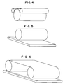
- Fig. 4 is a schematic view of the combination of a heat roll with a heat belt.
- Fig. 5 is a schematic view of the combination of a heat roll with a heat plate.
- Fig. 6 is a schematic view of the combination of a heat belt with a heat plate.
- Fig. 7 is a schematic view of a pair of heat rolls one of which has a groove cut in parallel with a film surface or a sheet surface.
- Fig. 8 is a schematic view of a pair of heat belts one of which has a groove cut in parallel with a film surface or a sheet surface.
- Fig. 9 is a schematic view of a pair of heat plates one of which has a groove cut in parallel with a film surface or a sheet surface.
- Fig. 10 is a schematic view of the combination of a heat roll having a groove cut in parallel with a film surface or a sheet surface with a heat belt.
- Fig. 11 is a schematic view of the combination of a heat roll and a heat plate having a groove cut in parallel with a film surface or sheet surface.
- Fig. 12 is a schematic view of the combination of a heat plate having a groove cut in parallel with a film surface or a sheet surface with a heat belt.
- a stretched thermoplastic resin film or sheet shrinks in the stretching direction when it is subjected to thermal relaxation in an unrestricted condition at a temperature not lower than the glass transition temperature of the thermoplastic resin.
- the film or sheet tends to expand in a direction parallel to the film or sheet surface and perpendicular to the stretching axis, because the film or sheet has a neck-in (shrinkage) generated during the stretching, in the direction parallel to the film or sheet surface and perpendicular to the stretching axis.
- the stretching axis refers to an axis of uniaxial stretching in the case of uniaxial stretching, and to an axis of main stretching in the case of unbalanced biaxial stretching.
- Direction parallel to the surface of the film or sheet and perpendicular to the stretching axis refers to a direction parallel to the surface and of 60-120° to stretching axis. Suppression of expansion in a direction of, in particular, 85-95° to stretching axis is preferable in view of the improvement in angular dependence of retardation. Suppression of expansion in a direction parallel to the film or sheet surface and perpendicular to the stretching axis, as compared with the suppression in other directions, gives higher improvement in angular dependence of retardation.
- “Suppression of expansion in a direction parallel to the film or sheet surface and perpendicular to the stretching axis” refers to keeping the expansion in said direction substantially at 0, i.e. keeping constant the length of the film or sheet in said direction and further making the expansion in said direction smaller than the level obtained when the film or sheet is subjected to thermal relaxation in an unrestricted condition until a desired R 0 value is attained.
- thermoplastic resin film or sheet there is no particular limitation to the method of continuously supplying the stretched thermoplastic resin film or sheet to a heating zone in parallel to the stretching direction, and heating the film or sheet to a temperature not lower than the glass transition temperature of the resin while applying pressure to the surface of the film or sheet, as far as the method does not make wrinkles in the film or sheet nor reduce the thickness of the film or sheet below that before the thermal relaxation.
- Such the method includes a method with a heating device provided with a mechanism described below, for example, a pair of such the heating devices.
- the mechanism is such that it has a space into which the film or sheet can be inserted, or produces a space necessary for the passage of the film or sheet by insertion thereof, in which space the passing film or sheet can be heated to a temperature not lower than the glass transition temperature of the resin while applying pressure to its surface.
- Such a pair of heating devices include paired heating devices which are arranged opposite to each other with a space therebetween which barely permits the insertion and passage of the film or sheet, and paired heating devices which are arranged opposite to each other and provided with a mechanism producing a space necessary for the passage of the film or sheet when the film or sheet is inserted. Further, these paired heating devices must have a mechanism which can give heat and apply pressure to the surface of the film or sheet passing through the space.
- the above heating devices are not critical, as far as they are provided with a mechanism which can heat the film or sheet to a temperature not lower than the glass transition temperature of the resin while applying pressure to the surface of the film or sheet.
- Figs. 1 to 6 having a mechanism which can apply pressure to the surface of the film or sheet.
- Fig. 1 shows a pair of heat rolls
- Fig. 2 shows a pair of heat belts
- Fig. 3 shows a pair of heat plates
- Fig. 4 shows the combination of a heat roll with a heat belt
- Fig. 5 shows the combination of a heat roll with a heat plate
- Fig. 6 shows the combination of a heat belt with a heat plate.
- Figs. 7 to 12 which are provided with a mechanism which can apply pressure to the film or sheet surface and one of which has a groove cut in parallel with the film or sheet surface.
- Fig. 7 shows a pair of heat rolls
- Fig. 8 shows a pair of heat belts
- Fig. 9 shows a pair of heat plates
- Fig. 10 shows the combination of a heat roll with a heat belt
- Fig. 11 shows the combination of a heat roll with a heat plate
- Fig. 12 shows the combination of a heat belt with a heat plate.
- pairs of heating device shown in Figs. 1 to 12 may be used, if necessary, in combination of the plural number of them.
- the rate, V 2 , of the film or sheet after passage through the heating zone can be made smaller than the rate, V 1 , of the film or sheet supplied to the heating zone.
- a phase retarder film or sheet having a low angular dependence of retardation and satisfying the following equation can be produced continuously: 0.900 ⁇ (R 40 /R 0 ) 2 ⁇ (R 40 /R 0 ) 1 wherein (R 40 /R 0 ) 1 is R 40 /R 0 of film or sheet before thermal relaxation and (R 40 /R 0 ) 2 is R 40 /R 0 of film or sheet after thermal relaxation.
- the pressure to be applied to the film or sheet surface is in the range of, for example, from 0.1 g/cm 2 to 10 kg/cm 2 .
- the stretched thermoplastic resin film or sheet may be any of those having a property to shrink in the direction of the stretching axis during thermal relaxation in the heating zone and to expand in the direction parallel to the film or sheet surface and perpendicular to the stretching axis.
- a method for producing such the film or sheet is not critical.
- a method of producing an unstretched film or sheet by the known film-forming techniques such as solution casting, press molding, extrusion molding and the like, and then stretching this unstretched film or sheet by the known stretching methods such as tentering, stretching between rolls, rolling (i.e. compressive stretching between rolls) and the like.
- the stretched thermoplastic resin film or sheet examples include a film or sheet longitudinally uniaxial-stretched in the lengthwise direction produced by the above method.
- a desirable film or sheet is one produced by making a film or sheet by solution casting and subjecting the resulting film or sheet to longitudinal uniaxial stretching between rolls.
- any temperature will do if it is not lower than the glass transition temperature (T g ) of the thermoplastic resin and lower than the melting point (T m ) and enables the thermal relaxation of the thermoplastic resin film or sheet.
- the temperature of thermal relaxation varies depending upon the T g and T m of the resin used, but is preferably in the range of T g to (T g + 50°C) in view of the control of in-plane retardation of the film or sheet and orientation of molecules in the direction of thickness.
- the film or sheet it is sufficient for the film or sheet to be heated above the glass transition temperature of the resin. Therefore, it doesn't matter if there is a difference in temperature between a pair of heating devices, and also, if the temperature of one of the heating devices is lower than the glass transition temperature of the resin, there is no problem if the temperature of the film or sheet is not lower than the glass transition temperature.
- a cushioning medium to at least one side of the stretched thermoplastic resin film or sheet because temperature and pressure are transferred to the film or sheet surface through the cushioning medium to reduce unevenness in temperature, pressure and the like during thermal relaxation.
- thermoplastic resin film or sheet between release agents (e.g. releasable polyester films) or to coat the surface of the film or sheet with a lubricant (e.g. silicone oil, molten surfactant) because the transformation rate increases and uniformity in the transformation rate improves during thermal relaxation.
- release agents e.g. releasable polyester films
- a lubricant e.g. silicone oil, molten surfactant
- thermoplastic resin is not critical as long as it has an intrinsic birefringence, but those which are superior in optical characteristics (e.g. transparency, etc.) are desirable.
- thermoplastic resins having a positive intrinsic birefringence include polycarbonate, polysulfone, polyarylate, polyethersulfone, cellulose diacetate and the like.
- thermoplastic resins having a negative intrinsic birefringence include polystyrene, ⁇ -methylpolystyrene, polyvinylpyridine, polyvinylnaphthalene, polymethyl methacrylate and the like.
- polycarbonate is preferred in terms of transparency, heat and humidity resistance, expression of birefringence and the like.
- This stretched film was interposed between two same releasable films (Cerapeel Q-1 #188 produced by Toyo Metallizing Co., Ltd.), and a silicone oil (KF-96-20CS produced by Shin-Etsu Chemical Co., Ltd.) was injected between the releasable films and stretched film.
- a silicone oil KF-96-20CS produced by Shin-Etsu Chemical Co., Ltd.
- the resulting sandwich together with a flannel having a thickness of 1500 ⁇ m under no load as a cushioning medium, was passed between a pair of rotating hot rolls (diameters of both the upper and lower rolls, 20 cm; surface temperatures of both the rolls, 160°C; and distance between rolls, 820 ⁇ m), with the cushioning medium below the sandwich.
- the sandwich was passed at a rate of 6 cm/min with its advance direction parallel to the direction of stretching axis of the stretched film. In this way, continuous thermal relaxation was carried out while suppressing the expansion of the film in the direction perpendicular to stretching axis.
- Example 2 The same stretched film as used in Example 1 was cut into a width of 20.0 cm. This stretched film was interposed between two same releasable films (Cerapeel Q-1 #188 produced by Toyo Metallizing Co., Ltd.), and a silicone oil (KF-96-20CS produced by Shin-Etsu Chemical Co., Ltd.) was injected between the releasable films and stretched film.
- a silicone oil KF-96-20CS produced by Shin-Etsu Chemical Co., Ltd.
- the sandwich was passed at a rate of 6 cm/min with its advance direction parallel to the direction of stretching axis of the stretched film. In this way, continuous thermal relaxation was carried out while suppressing the expansion of the film in the direction perpendicular to stretching axis.
- This stretched film was interposed between two same releasable films (Cerapeel Q-1 #188 produced by Toyo Metallizing Co., Ltd.), and a silicone oil (KF-96-20CS produced by Shin-Etsu Chemical Co., Ltd.) was injected between the releasable films and stretched film.
- a silicone oil KF-96-20CS produced by Shin-Etsu Chemical Co., Ltd.
- the resulting sandwich together with a flannel having a thickness of 1500 ⁇ m under no load as a cushioning medium, was passed between a pair of rotating hot rolls (diameters of both the upper and lower rolls, 20 cm; surface temperatures of both the rolls, 160°C; and distance between rolls, 920 ⁇ m), with the cushioning medium below the sandwich.
- the sandwich was passed at a rate of 6 cm/min with its advance direction parallel to the direction of stretching axis of the stretched film. In this way, continuous thermal relaxation was carried out while suppressing the expansion of the film in the direction perpendicular to stretching axis.
- This stretched film was interposed between two same releasable films (Cerapeel Q-1 #188 produced by Toyo Metallizing Co., Ltd.), and a silicone oil (KF-96-20CS produced by Shin-Etsu Chemical Co., Ltd.) was injected between the releasable films and stretched film.
- a silicone oil KF-96-20CS produced by Shin-Etsu Chemical Co., Ltd.
- the resulting sandwich together with a flannel having a thickness of 1500 ⁇ m under no load as a cushioning medium, was passed between a pair of rotating hot rolls (diameters of both the upper and lower rolls, 20 cm; surface temperatures of both the rolls, 160°C; and distance between rolls, 920 ⁇ m), with the cushioning medium below the sandwich.
- the sandwich was passed at a rate of 6 cm/min with its advance direction parallel to the direction of stretching axis of the stretched film. In this way, continuous thermal relaxation was carried out while suppressing the expansion of the film in the direction perpendicular to stretching axis.
- Example 2 The same stretched film as used in Example 1 was cut into a width of 20 cm. This stretched film was interposed between two same releasable films (Cerapeel Q-1 #188 produced by Toyo Metallizing Co., Ltd.), and a silicone oil (KF-96-20CS produced by Shin-Etsu Chemical Co., Ltd.) was injected between the releasable films and stretched film.
- a silicone oil KF-96-20CS produced by Shin-Etsu Chemical Co., Ltd.
- the resulting sandwich together with a flannel having a thickness of 1500 ⁇ m under no load as a cushioning medium, was passed between a pair of rotating hot rolls (diameters of both the upper and lower rolls, 20 cm; surface temperatures of both the rolls, 160°C; and distance between rolls, 700 ⁇ m), with the cushioning medium below the sandwich.
- the sandwich was passed at a rate of 6 cm/min with its advance direction parallel to the direction of stretching axis of the stretched film. In this way, continuous thermal relaxation was carried out while suppressing the expansion of the film in the direction perpendicular to stretching axis.
- Example 2 The same stretched film as used in Example 1 was interposed between two same releasable films (Cerapeel Q-1 #188 produced by Toyo Metallizing Co., Ltd.).
- the resulting sandwich together with a flannel having a thickness of 1500 ⁇ m under no load as a cushioning medium, was passed between a pair of rotating hot rolls (diameters of both the upper and lower rolls, 20 cm; surface temperatures of both the rolls, 160°C; and distance between rolls, 800 ⁇ m), with the cushioning medium below the sandwich.
- the sandwich was passed at a rate of 6 cm/min with its advance direction parallel to the direction of stretching axis of the stretched film. In this way, continuous thermal relaxation was carried out while suppressing the expansion of the film in the direction perpendicular to stretching axis.
- Example 2 The same stretched film as used in Example 1 was cut into a width of 20 cm.
- This stretched film was interposed between two same releasable films (Cerapeel Q-1 #188 produced by Toyo Metallizing Co., Ltd.) and passed between a pair of rotating hot rolls (diameters of both the upper and lower rolls, 20 cm; surface temperatures of both the rolls, 160°C; and distance between rolls, 500 ⁇ m) at a rate of 6 cm/min with its advance direction parallel to the direction of stretching axis of the stretched polycarbonate film. In this way, continuous thermal relaxation was carried out while suppressing the expansion of the film in the direction perpendicular to stretching axis.
- Example 2 The same stretched film as used in Example 1 was cut into a size of 10 cm in length (direction perpendicular to stretching axis) ⁇ 10 cm in width (stretching axis direction). This film was thermally relaxed for 4 minutes on a releasable film (Cerapeel Q-1 #188 produced by Toyo Metallizing Co., Ltd.) under a temperature condition of 158°C.
- a releasable film (Cerapeel Q-1 #188 produced by Toyo Metallizing Co., Ltd.) under a temperature condition of 158°C.
- this polycarbonate film changed to a size of 10.1 cm in length ⁇ 9.65 cm in width.
- the thickness, R 0 and R 40 /R 0 of this film were 141 ⁇ m, 415 nm and 1.118, respectively.
Landscapes
- Physics & Mathematics (AREA)
- General Physics & Mathematics (AREA)
- Optics & Photonics (AREA)
- Polarising Elements (AREA)
- Shaping By String And By Release Of Stress In Plastics And The Like (AREA)
Description
Claims (2)
- A process for producing a phase retarder film or sheet, comprising supplying a stretched thermoplastic resin film or sheet to a heating zone and heating the film or sheet to a temperature not lower than the glass transition temperature of the resin while applying pressure to the surface of the film or sheet passing through the heating zone, wherein the stretched thermoplastic resin or sheet is continuously supplied to the heating zone in parallel with the stretching direction of the film or sheet, thereby continuously subjecting the film or sheet to thermal relaxation while suppressing the expansion of the film or sheet in a direction parallel to the surface of the film or sheet and perpendicular-to the stretching axis.
- A process according to Claim 1, wherein the heating zone is a pair of heat rolls.
Applications Claiming Priority (2)
| Application Number | Priority Date | Filing Date | Title |
|---|---|---|---|
| JP5084439A JPH06300916A (en) | 1993-04-12 | 1993-04-12 | Production of phase difference film |
| JP84439/93 | 1993-04-12 |
Publications (3)
| Publication Number | Publication Date |
|---|---|
| EP0620457A2 EP0620457A2 (en) | 1994-10-19 |
| EP0620457A3 EP0620457A3 (en) | 1995-02-22 |
| EP0620457B1 true EP0620457B1 (en) | 1998-06-10 |
Family
ID=13830630
Family Applications (1)
| Application Number | Title | Priority Date | Filing Date |
|---|---|---|---|
| EP94301769A Expired - Lifetime EP0620457B1 (en) | 1993-04-12 | 1994-03-11 | Process for producing phase retarder film |
Country Status (4)
| Country | Link |
|---|---|
| US (1) | US5474731A (en) |
| EP (1) | EP0620457B1 (en) |
| JP (1) | JPH06300916A (en) |
| DE (1) | DE69410872T2 (en) |
Families Citing this family (15)
| Publication number | Priority date | Publication date | Assignee | Title |
|---|---|---|---|---|
| TW388000B (en) * | 1994-02-28 | 2000-04-21 | Sumitomo Chemical Co | Phase retarder film and process for producing same |
| TW327208B (en) * | 1994-11-10 | 1998-02-21 | Sumitomo Chemical Co | Optically anisotropic film and process for producing the same and liquid crystal display device |
| JPH08278410A (en) * | 1995-04-10 | 1996-10-22 | Sumitomo Chem Co Ltd | Optical anisotropic film, method for producing the same, and liquid crystal display device |
| US5638200A (en) * | 1995-02-03 | 1997-06-10 | Ois Optical Imaging Systems, Inc. | Liquid crystal display with tilted retardation film |
| US5948487A (en) * | 1997-09-05 | 1999-09-07 | 3M Innovative Properties Company | Anisotropic retardation layers for display devices |
| US5867239A (en) * | 1997-10-17 | 1999-02-02 | Minnesota Mining And Manufacturing Company | Wide angle optical retarder |
| TW490576B (en) | 1998-09-17 | 2002-06-11 | Sumitomo Chemical Co | Optically anisotropic film, method of manufacturing the same, and liquid crystal display apparatus |
| US6538714B1 (en) | 1999-10-25 | 2003-03-25 | 3M Innovative Properties Company | Dual color guest-host polarizers and devices containing guest-host polarizers |
| US6574044B1 (en) * | 1999-10-25 | 2003-06-03 | 3M Innovative Properties Company | Polarizer constructions and display devices exhibiting unique color effects |
| US6465002B1 (en) | 2000-03-13 | 2002-10-15 | Brown University Research Foundation | Liquid crystalline polymers |
| CN100498384C (en) * | 2000-12-04 | 2009-06-10 | 富士胶片株式会社 | Optical compensating sheet having optically anisotropic layer made of discotic liquid-crystalline molecules and transparent substrate comprising polymer film |
| JP2004004150A (en) * | 2002-05-13 | 2004-01-08 | Sumitomo Chem Co Ltd | Laminated retardation film and liquid crystal display device using the same |
| JP5891170B2 (en) * | 2010-06-11 | 2016-03-22 | 三菱瓦斯化学株式会社 | Aromatic polycarbonate polarizing lens |
| US20140264979A1 (en) * | 2013-03-13 | 2014-09-18 | Transitions Opticals, Inc. | Method of preparing photochromic-dichroic films having reduced optical distortion |
| CN106918863B (en) * | 2017-05-12 | 2019-09-13 | 京东方科技集团股份有限公司 | Phase film substrate, manufacturing method thereof, and display device |
Family Cites Families (24)
| Publication number | Priority date | Publication date | Assignee | Title |
|---|---|---|---|---|
| NL294487A (en) * | 1962-06-25 | |||
| US3290420A (en) * | 1962-07-05 | 1966-12-06 | Columbian Rope Co | Process for making thin oriented plastic strips and tape |
| NL159416B (en) * | 1966-10-13 | 1979-02-15 | Hoechst Ag | PROCESS OF MANUFACTURING A POLYESTERFOELY WITH SMALL CRYSTALS. |
| US3679791A (en) * | 1970-02-20 | 1972-07-25 | Ici Ltd | Process for shrinking film |
| US4151245A (en) * | 1972-12-06 | 1979-04-24 | Matsushita Electric Industrial Co., Ltd. | Method for stretching a thermo-softening high molecular film |
| US4160799A (en) * | 1976-09-29 | 1979-07-10 | Eastman Kodak Company | Maintaining planarity in polyester film during uniform temperature heat relaxation |
| US4436888A (en) * | 1982-10-05 | 1984-03-13 | E. I. Du Pont De Nemours And Company | Method for making balanced low shrink tension polyolefin film |
| JPS61167531A (en) * | 1985-01-21 | 1986-07-29 | Diafoil Co Ltd | Polyester film for magnetic sheet |
| US5061042A (en) * | 1987-02-02 | 1991-10-29 | Sumitomo Chemical Co., Ltd. | Phase retarder and liquid crystal display using the same |
| JPS6485734A (en) * | 1988-08-17 | 1989-03-30 | Asahi Chemical Ind | Heat treatment equipment of band-like body |
| JP2606894B2 (en) * | 1988-08-18 | 1997-05-07 | チッソ株式会社 | Rolled heat-treated film or sheet manufacturing method |
| JPH0830765B2 (en) * | 1988-09-26 | 1996-03-27 | 富士写真フイルム株式会社 | Method of manufacturing retardation film |
| JPH02191904A (en) * | 1988-09-26 | 1990-07-27 | Fuji Photo Film Co Ltd | Phase difference film and its production |
| JP2612196B2 (en) * | 1988-12-14 | 1997-05-21 | 富士写真フイルム株式会社 | Phase difference film and method of manufacturing the same |
| US5244713A (en) * | 1988-12-27 | 1993-09-14 | Sumitomo Chemical Co., Ltd. | Optical film |
| KR920007285B1 (en) * | 1989-03-10 | 1992-08-29 | 구레하 가가꾸 고오교 가부시끼가이샤 | Optical phase plate and production process thereof |
| JPH02285303A (en) * | 1989-04-26 | 1990-11-22 | Nitto Denko Corp | Double refractive film and production thereof and phase difference plate and liquid crystal panel |
| JP2592697B2 (en) * | 1990-02-13 | 1997-03-19 | 富士写真フイルム株式会社 | Method for manufacturing retardation film |
| DE69127319T2 (en) * | 1990-05-25 | 1998-03-19 | Sumitomo Chemical Co | Optical phase retarder made of a polymer film and process for its production |
| JPH04138424A (en) * | 1990-09-28 | 1992-05-12 | Sharp Corp | Liquid crystal display device |
| DE69124911T2 (en) * | 1990-10-24 | 1997-06-19 | Nitto Denko Corp | Birefringent film, process for its production, retarding film, elliptical polarizer and liquid crystal display device |
| JP3220478B2 (en) * | 1991-06-07 | 2001-10-22 | 日本ゼオン株式会社 | Phase plate for liquid crystal display |
| EP0546748B1 (en) * | 1991-12-09 | 1997-05-07 | Sumitomo Chemical Company Limited | Process for producing phase retarder from a thermoplastic resin film or sheet |
| JPH0611710A (en) * | 1992-04-27 | 1994-01-21 | Kanegafuchi Chem Ind Co Ltd | Liquid crystal display element |
-
1993
- 1993-04-12 JP JP5084439A patent/JPH06300916A/en active Pending
-
1994
- 1994-03-11 EP EP94301769A patent/EP0620457B1/en not_active Expired - Lifetime
- 1994-03-11 DE DE69410872T patent/DE69410872T2/en not_active Expired - Fee Related
- 1994-04-12 US US08/226,465 patent/US5474731A/en not_active Expired - Fee Related
Also Published As
| Publication number | Publication date |
|---|---|
| EP0620457A2 (en) | 1994-10-19 |
| US5474731A (en) | 1995-12-12 |
| EP0620457A3 (en) | 1995-02-22 |
| DE69410872D1 (en) | 1998-07-16 |
| JPH06300916A (en) | 1994-10-28 |
| DE69410872T2 (en) | 1998-10-08 |
Similar Documents
| Publication | Publication Date | Title |
|---|---|---|
| EP0546748B1 (en) | Process for producing phase retarder from a thermoplastic resin film or sheet | |
| US5472538A (en) | Process for producing phase retarder film | |
| HK1000915B (en) | Process for producing phase retarder from a thermoplastic resin film or sheet | |
| US5474731A (en) | Process for producing phase retarder film | |
| JP4790890B2 (en) | Retardation film and continuous production method thereof | |
| KR20080094612A (en) | Heat treatment method of thermoplastic film, thermoplastic film and manufacturing method thereof | |
| US5699136A (en) | Negative uniaxial anisotropic element and method for manufacturing the same | |
| KR101464217B1 (en) | Thermoplastic resin film and method of manufacturing the same | |
| KR101408387B1 (en) | OPTICAL COMPENSATION FILM, PROCESS FOR PRODUCING THE SAME, POLARIZING PLATE, | |
| EP0458635B1 (en) | Polymeric film optical phase retarder and process for its production | |
| JP2005254812A (en) | Method for producing stretched film made of thermoplastic norbornene resin and retardation film | |
| JP3168850B2 (en) | Method for producing retardation film | |
| JP3309452B2 (en) | Method for producing retardation film | |
| US20090128747A1 (en) | Method for Producing Cellulose Acylate Film, Polarizing Plate and Liquid Crystal Display | |
| JP2001147323A (en) | Laminated retarder, elliptically polarizing plate, and liquid crystal display | |
| JP5186187B2 (en) | Thermoplastic resin film and method for producing the same, polarizing plate, optical compensation film, antireflection film, and liquid crystal display device | |
| JP2001059907A (en) | Phase difference plate and manufacturing method thereof | |
| JP2000231016A (en) | Manufacturing method of retardation plate | |
| JP2001013324A (en) | Manufacturing method of retardation plate | |
| JP2008039808A (en) | Production method of retardation film, retardation film, composite polarizing plate and polarizing plate | |
| JP2000111732A (en) | Method for producing three-dimensional birefringent film | |
| JP3383359B2 (en) | Method for manufacturing retardation film | |
| JP3889860B2 (en) | Retardation film | |
| JP4543915B2 (en) | Resin film | |
| JP2000162436A (en) | Method for manufacturing retardation film, optical member, and liquid crystal display device |
Legal Events
| Date | Code | Title | Description |
|---|---|---|---|
| PUAI | Public reference made under article 153(3) epc to a published international application that has entered the european phase |
Free format text: ORIGINAL CODE: 0009012 |
|
| AK | Designated contracting states |
Kind code of ref document: A2 Designated state(s): DE FR NL |
|
| PUAL | Search report despatched |
Free format text: ORIGINAL CODE: 0009013 |
|
| AK | Designated contracting states |
Kind code of ref document: A3 Designated state(s): DE FR NL |
|
| 17P | Request for examination filed |
Effective date: 19950330 |
|
| 17Q | First examination report despatched |
Effective date: 19961104 |
|
| GRAG | Despatch of communication of intention to grant |
Free format text: ORIGINAL CODE: EPIDOS AGRA |
|
| GRAG | Despatch of communication of intention to grant |
Free format text: ORIGINAL CODE: EPIDOS AGRA |
|
| GRAH | Despatch of communication of intention to grant a patent |
Free format text: ORIGINAL CODE: EPIDOS IGRA |
|
| GRAH | Despatch of communication of intention to grant a patent |
Free format text: ORIGINAL CODE: EPIDOS IGRA |
|
| GRAA | (expected) grant |
Free format text: ORIGINAL CODE: 0009210 |
|
| AK | Designated contracting states |
Kind code of ref document: B1 Designated state(s): DE FR NL |
|
| REF | Corresponds to: |
Ref document number: 69410872 Country of ref document: DE Date of ref document: 19980716 |
|
| ET | Fr: translation filed | ||
| PGFP | Annual fee paid to national office [announced via postgrant information from national office to epo] |
Ref country code: FR Payment date: 19990330 Year of fee payment: 6 |
|
| PGFP | Annual fee paid to national office [announced via postgrant information from national office to epo] |
Ref country code: NL Payment date: 19990331 Year of fee payment: 6 |
|
| PLBE | No opposition filed within time limit |
Free format text: ORIGINAL CODE: 0009261 |
|
| STAA | Information on the status of an ep patent application or granted ep patent |
Free format text: STATUS: NO OPPOSITION FILED WITHIN TIME LIMIT |
|
| PGFP | Annual fee paid to national office [announced via postgrant information from national office to epo] |
Ref country code: DE Payment date: 19990528 Year of fee payment: 6 |
|
| 26N | No opposition filed | ||
| PG25 | Lapsed in a contracting state [announced via postgrant information from national office to epo] |
Ref country code: NL Free format text: LAPSE BECAUSE OF NON-PAYMENT OF DUE FEES Effective date: 20001001 |
|
| PG25 | Lapsed in a contracting state [announced via postgrant information from national office to epo] |
Ref country code: FR Free format text: LAPSE BECAUSE OF NON-PAYMENT OF DUE FEES Effective date: 20001130 |
|
| NLV4 | Nl: lapsed or anulled due to non-payment of the annual fee |
Effective date: 20001001 |
|
| REG | Reference to a national code |
Ref country code: FR Ref legal event code: ST |
|
| PG25 | Lapsed in a contracting state [announced via postgrant information from national office to epo] |
Ref country code: DE Free format text: LAPSE BECAUSE OF NON-PAYMENT OF DUE FEES Effective date: 20010103 |