EP0620054B1 - Refuse treating apparatus - Google Patents
Refuse treating apparatus Download PDFInfo
- Publication number
- EP0620054B1 EP0620054B1 EP94105625A EP94105625A EP0620054B1 EP 0620054 B1 EP0620054 B1 EP 0620054B1 EP 94105625 A EP94105625 A EP 94105625A EP 94105625 A EP94105625 A EP 94105625A EP 0620054 B1 EP0620054 B1 EP 0620054B1
- Authority
- EP
- European Patent Office
- Prior art keywords
- temperature
- refuse
- condenser
- drying process
- treating apparatus
- Prior art date
- Legal status (The legal status is an assumption and is not a legal conclusion. Google has not performed a legal analysis and makes no representation as to the accuracy of the status listed.)
- Expired - Lifetime
Links
Images







Classifications
-
- B—PERFORMING OPERATIONS; TRANSPORTING
- B02—CRUSHING, PULVERISING, OR DISINTEGRATING; PREPARATORY TREATMENT OF GRAIN FOR MILLING
- B02C—CRUSHING, PULVERISING, OR DISINTEGRATING IN GENERAL; MILLING GRAIN
- B02C17/00—Disintegrating by tumbling mills, i.e. mills having a container charged with the material to be disintegrated with or without special disintegrating members such as pebbles or balls
- B02C17/002—Disintegrating by tumbling mills, i.e. mills having a container charged with the material to be disintegrated with or without special disintegrating members such as pebbles or balls with rotary cutting or beating elements
-
- B—PERFORMING OPERATIONS; TRANSPORTING
- B09—DISPOSAL OF SOLID WASTE; RECLAMATION OF CONTAMINATED SOIL
- B09B—DISPOSAL OF SOLID WASTE NOT OTHERWISE PROVIDED FOR
- B09B3/00—Destroying solid waste or transforming solid waste into something useful or harmless
- B09B3/30—Destroying solid waste or transforming solid waste into something useful or harmless involving mechanical treatment
- B09B3/38—Stirring or kneading
-
- F—MECHANICAL ENGINEERING; LIGHTING; HEATING; WEAPONS; BLASTING
- F26—DRYING
- F26B—DRYING SOLID MATERIALS OR OBJECTS BY REMOVING LIQUID THEREFROM
- F26B11/00—Machines or apparatus for drying solid materials or objects with movement which is non-progressive
- F26B11/12—Machines or apparatus for drying solid materials or objects with movement which is non-progressive in stationary drums or other mainly-closed receptacles with moving stirring devices
- F26B11/14—Machines or apparatus for drying solid materials or objects with movement which is non-progressive in stationary drums or other mainly-closed receptacles with moving stirring devices the stirring device moving in a horizontal or slightly-inclined plane
-
- F—MECHANICAL ENGINEERING; LIGHTING; HEATING; WEAPONS; BLASTING
- F26—DRYING
- F26B—DRYING SOLID MATERIALS OR OBJECTS BY REMOVING LIQUID THEREFROM
- F26B25/00—Details of general application not covered by group F26B21/00 or F26B23/00
- F26B25/22—Controlling the drying process in dependence on liquid content of solid materials or objects
Definitions
- the present invention relates to a refuse treating apparatus for treating refuse, mainly domestic kitchen waste.
- a garbage processing device wherein a shredding device is provided at the bottom of a rotatably arranged tub and furthermore, comprising a heatable compressor plate.
- Kitchen waste is shredded compressed and heated between the bottom of the tub and the corn plate whereupon the compressor plate is raised and the shredded garbage is removed.
- EP-A-165578 there is known a device for controlling the temperature of a cut tobacco leaves drying apparatus including a cylindrical rotor having a plurality of heating means which are arrayed in an advance direction of raw material independently of each other.
- the heating means is controlled in accordance with a pre-set value in order to provide an optimum drying temperature for tobacco.
- the refuse treating apparatus is classified into the combustion heat method, microwave method and electric heater method, by the type of heating source.
- the refuse treating apparatus of combustion heat method employs gas fuel or liquid fuel, and the entire apparatus is large and complicated, and involves a safety problem.
- the refuse treating apparatus of microwave method is suited to drying process of moist waste because the microwaves are selectively adsorbed in the moisture in the waste, but is slightly inferior in safety and controllability.
- the refuse treating apparatus of electric heater method is excellent in safety and controllability, and is small in size, and hence the cost can be reduced.
- the heater surrounding temperature when heating the refuse by the heater, in order to generate steam from the refuse, the heater surrounding temperature must be set over 100°C to obtain overheated steam, and when continued to heat in this state, if drying is over, the temperature change is small (nearly same as the heater set temperature), and it is hard to detect the drying end time. If the drying end time is not detected accurately, drying time becomes longer, and the heating cost is wasteful, or the refuse is scorched, which is not sanitary.
- the heating means when the heating means is operated after charging the refuse into the refuse container, the air around the heated heating means begins to heat the refuse.
- the refuse temperature goes up, and soon the refuse is dried while generating steam.
- the heating means output is controlled by the first temperature detecting means, and drying process is continued while preventing scorching of refuse.
- the steam volume decreases, and the temperature of the outer wall of the condenser drops. Therefore, when the temperature change of the second temperature detecting means provided on the outer wall of the condenser exceeds a specific value, the drying process is terminated, so that the drying end time can be detected accurately without allowing to scorch.
- the dried refuse remains in the refuse container, but the bulk is decreased and the moisture activity is lowered by drying, and therefore it is free from rot or mold if left over in the refuse container. Therefore, until the refuse container is filled up, fresh refuse can be successively put on the dried refuse and dried.
- the drying process can be terminated when the temperature of the condenser is lowered by a specific value from the maximum value, and continuously in a specific time, during drying process.
- a steam passage for the steam flowing out from the refuse container to the condenser is provided near the second temperature detecting means for detecting the temperature of the steam flowing out from the refuse container to the condenser at the condenser.
- the second temperature detecting means is more sensible to the heat of the steam, and the temperature change can be detected more accurately. Therefore, by terminating the drying process when the temperature change of the second temperature detecting means provided on the outer wall of the condenser exceeds a specific value, the drying end time can be detected accurately without allowing to scorch.
- third temperature detecting means for detecting the refuse temperature is attached to the lower outer wall of the refuse container, and the drying process is terminated when the change of temperature detected by the third temperature detecting means exceeds a specific value.
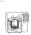
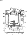
- Fig. 1 is a sectional view of a refuse treating apparatus in a first embodiment of the invention.
- Fig. 2 is a sectional view of a refuse treating apparatus in a second embodiment of the invention.
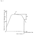
- Fig. 3 is a diagram showing the drying end detection of a refuse treating apparatus in a third embodiment of the invention.
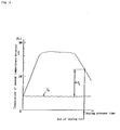
- Fig. 4 is a diagram showing the drying end detection of a refuse treating apparatus in a fourth embodiment of the invention.
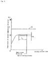
- Fig. 5 is a diagram showing the drying end detection of a refuse treating apparatus in a fifth embodiment of the invention.
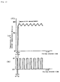
- Fig. 6 (a), (b) are timing charts of temperature measurement of a refuse treating apparatus in a seventh embodiment of the invention.
- Fig. 7 is a system configuration diagram of a refuse treating apparatus in an eighth embodiment of the invention.
- Fig. 8 is a diagram showing the drying detection of the refuse treating apparatus.
- Fig. 9 is an operation flow chart of essential parts of the refuse treating apparatus.
- Fig. 10 is a system configuration diagram of a refuse treating apparatus in a ninth embodiment of the invention.
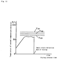
- Fig. 11 is a diagram showing a blank detection of the refuse treating apparatus.
- Fig. 12 (a), (b) are timing charts of temperature measurement of a refuse treating apparatus in a tenth embodiment of the invention.
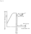
- Fig. 13 is a diagram showing the drying process of a refuse treating apparatus in an eleventh embodiment of the invention.
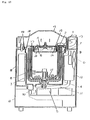
- Fig. 14 is a sectional view of a refuse treating apparatus in a twelfth embodiment of the invention.
- Fig. 15 is a sectional view of the refuse treating apparatus.
- Fig. 16 is a perspective exploded view of heating means of the refuse treating apparatus.
- Fig. 17 is a sectional view of a refuse treating apparatus in a thirteenth embodiment of the invention.
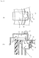
- Fig. 18 (a) is a magnified sectional view of part C in Fig. 17, and Fig. 18 (b) is a magnified top view of part C in Fig. 17.
- Fig. 19 is a sectional view of a refuse treating apparatus in a fourteenth embodiment of the invention.
- Fig. 20 is a sectional view of a refuse treating apparatus in a fifteenth embodiment of the invention.
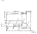
- Fig. 21 is a diagram showing the relation of temperature and time of parts during operation of the refuse treating apparatus.
- an insulated container 1 has a refuse container 2 installed detachably inside, and a stationary blade 3 is provided in the inner wall of the refuse container 2.
- a rotary blade 4 is linked to a rotary shaft motor 5.
- a first temperature detector (first temperature detecting means) 6 is positioned near the refuse container 2 so as to detect the ambient temperature in the refuse container 2.
- a second temperature detector (second temperature detecting means) 7 is installed on the outer wall of a condenser 8 in order to detect the temperature of the steam flowing out from the refuse container 2 into the condenser 8.
- the condenser 8 and a cooling fan 9 for air cooling the outer surface of the condenser 8 are installed.
- an condensate flow-out unit 10 is provided, and a catalytic device 12 is connected to a gas exhaust pipe 11 for discharging the gas (containing odor) generated from the refuse 21 from part of the condensate flow-out unit 10.
- a condensate container 13 is provided.
- an agitation fan 15 and a heater 16 are installed as heating means in the lid 14.
- the lid 14 is opened and closed by a hinge 17 to cover a refuse treating apparatus main body 18, and the lid 14 is also provided with a lid packing 19 in order to prevent leak of steam generated from the refuse 21.
- a certain gap is provided among the insulated container 1, the upper end of the refuse container 2, and the lower surface of the lid 14, and a passage of steam generated from the refuse 21 is formed.
- a hood 20 prevents the hot air by the agitation fan 15 and heater 16 from escaping by a short cut through the gap between the refuse container 2 and lid 14, and guides the hot air to be supplied effectively to the refuse 21.
- the refuse 21 put into the refuse container 2 is stirred by the rotary blade 4 and ground by the rotary blade 4 and stationary blade 3.
- the hot air by the agitation fan 15 and heater 16 circulates in the space formed by the lower surface of the lid 14, hood 20 and the refuse container 2, and the refuse 21 is heated while stirring the air in this space.
- the output of the heater 16 is controlled by the output of the first temperature detector 6 so that the ambient temperature in the refuse container 2 may be a specified temperature, and the drying process is continued while preventing scorching of the refuse 21.
- the drying process is continued by controlling the output of the heater 16 so that the ambient temperature in the refuse container 2 may reach the specified temperature by the first temperature detector 6, and the steam generation decreases as approaching the end of drying, and hence the temperature of the outer wall of the condenser 8 drops, and the drying process is terminated when the temperature change of the second temperature detector 7 following it exceeds the specified value, so that end of drying is known accurately without causing scorching.
- the first temperature detector 6 is positioned on the metal hood 20 installed in the lid 14 provided above the refuse container 2 so as to detect the ambient temperature in the refuse container 2.
- the output of the first temperature detector 6 is controlled so that the ambient temperature in the refuse container 2 may be a specified value, and same as in the first embodiment, the drying process can be continued while preventing scorching of the refuse 21.
- the first temperature detector 6 is installed on the hood 20 the precision of temperature detection in the refuse container 2 is high, and since it is not exposed to steam, a thermistor can be used for the temperature detector 6.
- the drying process is terminated when the temperature of the outer wall of the condenser 8 in the drying process is lowered by a specific amount from the maximum value.
- the other constitution is same as in the first embodiment.
- the drying process is terminated when the temperature of the second temperature detector 7 provided on the outer wall of the condenser 8 is lowered by the specified amount from the maximum value in the midst of drying, the end of drying process is detected by one temperature detector, and hence it is stable with less error and the cost can be cut.
- the drying process is terminated when the temperature of the outer wall of the condenser 8 reaches a specific value, by correcting the effects of ambient temperature, in the midst of drying process.
- the other constitution is same as in the first embodiment.
- the drying process is terminated when the temperature of the second temperature detector 7 provided on the outer wall side of the condenser 8 reaches the specified value by correcting the effects of ambient temperature, the end of drying can be detected stably without effects of changes of ambient temperature.
- the empty state in the refuse container 2 is detected by the output of the second temperature detector 7 provided on the outer wall of the condenser 8, and the drying process is terminated, and empty drying can be prevented, so that extra electric power can be saved.
- the power supply to the heater 16 is stopped only the temperature is lowered by more than the set temperature from the maximum temperature, malfunction does not occur even if the ambient temperature changes, and the drying process can be terminated precisely.
- the temperature of the condenser 8 in the drying process is measured at the same timing as the on/off period of the rotary blade 4.
- the other constitution is same as in the first embodiment.
- Fig. 6 (a), (b) are magnified views of temperature of second temperature detector 7 in coincidence with on/off of the rotary blade 4, and the temperature of the second temperature detector 7 is varied as shown in Fig. 6 (a) in coincidence with on/off the rotary blade 4 as shown in Fig. 6 (b). That is, when the rotary blade 4 is off, the steam generation is increased, and when it is on, the steam generation decreases due to agitation with the cold refuse 21, so that the temperature detected by the second temperature detector 7 varies.
- control means 22 possesses a timer function inside, the output of the first temperature detector 6 and the output of the second temperature detector 7 are fed through input means 23, and the output of the motor 16 is controlled through output means 24, and the drying process is carried out while controlling the agitation fan 15 and cooling fan 9, and the drying is terminated when the temperature change of the second temperature detector 7 continues to be over the specified amount from the maximum value in the drying process longer than the specified time.
- the control means 22 monitors the temperature change of the second temperature detector 7 at step 31 as shown in Fig. 9, and the internal timer is cleared at step 32 until reaching the specified value to return to step 31.
- the drying process is terminated. In this way, without error in detecting the end due to temperature change during drying process, the drying end time can be detected accurately, without allowing to scorch.
- the specified amount may be smaller, and scorching may be prevented.
- the specified time longer than the temperature change time during drying process, earlier ending of drying process can be securely inhibited.
- the first temperature detector 6 is used for temperature adjustment of the heater 16, but the temperature of the heater 16 may be controlled constant by using temperature regulator such as bimetal without using first temperature detector 6.
- ambient temperature measuring means 25 is mounted on the refuse treating apparatus main body 18 for measuring the ambient temperature, and its output is fed into control means 26.
- the control means 26 set the specified temperature for judging the empty state which is determined by the ambient temperature as the temperature of the condenser 8 in the drying process, and when the temperature of the condenser 8 continues to be below the specified temperature for more than a specified time, the refuse container 2 is judged to be empty, and drying process is terminated.
- the specified temperature T01 for judging the empty state in the refuse container 2 is 75°C when the ambient temperature is 40°C
- the specified temperature T02 is 70°C when the ambient temperature is 20°C
- the specified temperature T03 is 65°C when the ambient temperature is 0°C.
- the refuse container 2 when the temperature of the condenser 8 in the drying process maintains below the specified temperature determined by the ambient temperature for the specified time, the refuse container 2 is judged to be empty, and the drying process is terminated, so that the effects of ambient temperature can be ignored.
- the control means 26 in Fig. 8 controls the temperature measurement of the condenser 8 in the drying process to be effected in every timing same as the on/off period of the rotary blade 4.
- the other constitution is the same as in the eighth embodiment.
- Fig. 12 (a), (b), are magnified views of the temperature of the second temperature detector 7 matched with on/off of the rotary blade 4, and by matching with on/off of the rotary blade 4 shown in Fig. 12 (b), the temperature of the second temperature detector 7 is varies as shown in Fig. 12 (a). That is, when the rotary blade 4 is off, the steam generation increases, and when it is on, the steam generation is decreased due to agitation with the cold refuse 21, thereby varying the temperature of the second temperature detector 7.
- the control means controls to measure the temperature of the second temperature detector 7 in the delay of temperature measurement of outer wall of the condenser 8 in the drying process by time ⁇ t2 (several milliseconds) after the rotary blade 4 is off, so that the effects of temperature changes of the second temperature detector 7 caused by on/off of the rotary blade 4 can be ignored.
- the rotary blade 4 while the rotary blade 4 is off, the steam generation is large and the temperature change of the steam temperature detector is large, but sine the temperature is measured always at the same timing of on/off period of the rotary blade 4, the quantity of steam generation can be ignored.
- the rotary blade 4 is off, but it is the same when it is on.
- the control means 26 in Fig. 8 is designed to operate the heater 16 for a specific time after start of processing.
- the other constitution is same as in the eighth embodiment.
- the insulated container 1, upper end of the refuse container 2, and the lower surface of the lid 14 are disposed across a specific gap 27, and a steam passage of the steam generated from the refuse 21 flowing out from the refuse container 2 into the condenser 8 is formed.
- the upper part of the condenser 8 is formed in two stages, and the inside diameter of the upper stage is set larger than the lower stage to form a steam reservoir 28, and on the outer wall of the steam reservoir 28 and on the outer wall of the condenser 8 confronting the cooling fan 9 as shown in Fig. 15, a second temperature detector 7 is attached.
- an air guide 29 is provided in the rear part of the agitation fan 15, and the air guide 29 functions effectively for blowing out the hot air by the agitation fan 15 and heater 16 in the forward direction, and a fan cover 30 prevents the hot air from escaping by a short cut through the gap 27 between the refuse container 2 and the lower surface of the lid 14, so as to be supplied effectively into the refuse 21.
- the refuse 21 charged into the refuse container 2 is stirred by the rotary blade 4, and is ground by the rotary blade 4 and stationary blade 3.
- the hot air by the agitation fan 15 and heater 16 circulates in the space formed by the lower surface of the lid 14, fan cover 30 and the refuse container 2, and the refuse 21 is heated while stirring the air in this space.
- the output of the heater 16 is controlled by the output of the first temperature detector 6 so that the ambient temperature in the refuse container 2 may be a specified temperature, and the drying process is continued while preventing scorching of the refuse 21.
- the second temperature detector 7 is more sensible to the heat of steam, and the temperature change can be detected more accurately.
- the upper end of the refuse container 2 and the lower surface of the lid 14 are disposed across a specific gap, and the steam passage for flowing out from the refuse container 2 to the condenser 8 is formed, the steam generated by the heated refuse passes through the steam passage having a specific gap against the upper end of the refuse container 2 and the lower surface of the lid 14, and flows out to the condenser 8.
- the upper part of the condenser 8 is designed in two-stage structure with the inside diameter of the upper stage larger than that of the lower stage, and a second temperature detector 7 is attached to the outer wall of the upper stage, and therefore a steam reservoir 28 is formed as the inside diameter of the upper stage is larger than that of the lower stage, and by attaching the second temperature detector 7 to the outer wall of the steam reservoir 28, the steam temperature can be detected stably.
- the temperature change value at the drying end point of the second temperature detector 7 may be set large, so that the end of drying can be detected accurately.
- a recess 36 is formed in a part facing the steam passage from the upper end of the refuse container 2 to the condenser 8, and second temperature detecting means 7 is provided near (part A) the recess 36.
- the steam generated from the refuse container 2 reaches the condenser 8 by passing through the steam passage formed by the whole circumference of the upper end of the refuse container 2 and the lid 14, but the sectional area of the steam passage is wider because the recess 36 is partly formed as compared with other parts than the recess 36. Accordingly, the steam generated from the refuse container 2 flows more into the recess 36 than in other parts. Therefore, as the drying of the refuse in the refuse container 2 is advanced and the steam volume decreases, the steam volume in the recess 36 decreases (changes) significantly.
- the second temperature detecting means 7 is provided near the recess 36 where the steam volume changes significantly, decrease of steam volume, or the drying end point can be detected securely, so that highly precise drying control is realized.
- the second temperature detecting means 7 is provided inside the lid 14 and above the recess 36, but the same effects are obtained if provided above the condenser 8 in the position (part B) confronting the recess 36.
- the gap a formed by the refuse container 2 and the condenser 8 is set larger than the gap b formed between the upper end of the refuse container 2 and the inner surface of the lid 14.
- the refuse charged into the refuse container 2 is heated by the heater 16, and heat is diffused within the refuse container 2 by the agitation fan 15.
- the steam generated from the refuse passes through the gap b between the upper end of the refuse container 2 and the inner surface of the lid 14, and flows out to the condenser 8 at the outside of the refuse container 2.
- the steam is cooled and condensed in the condenser 8.
- the gap a formed between the refuse container 2 and the condenser 8 is set larger than the gap b formed between the upper end of the refuse container 2 and inner surface of the lid 14, and therefore when the steam released from the refuse container 2 flows into the condenser 8, it is instantly expanded and diffused and the steam spreads in the condenser 8, and the temperature in the condenser 8 becomes uniform, so that the temperature detection precision by the second temperature detector 7 may be heightened.
- the generated steam massively spreads in the condenser 8 and the temperature detection precision by the second temperature detector 7 can be enhanced, so that drying process can be terminated precisely.
- insulated container is not provided, but it may be also provided outside of the refuse container 2 same as in the first embodiment.
- the second temperature detector 7 is provided on the outer wall of the condenser 8, but it may be placed in any position where the temperature of the steam generated from the refuse in the refuse container 2 can be detected, for example, inward of the lid packing 19 on the inner surface of the lid 14.
- a third temperature detector (third temperature detecting means) 37 is mounted on the lower outer wall of the refuse container 2, and the refuse temperature is detected. When the change of temperature detected by the third temperature detector 37 exceeds a specific value, drying process is terminated.
- Fig. 21 shows an entire process, consisting of a drying step comprising a first drying stage and a second drying stage, and a cooling step.
- solid line A denotes the temperature transition in the refuse container 2 detected by the first temperature detector 6
- solid line B indicates the temperature transition of the refuse detected by the third temperature detector 37 attached to the lower outer wall of the refuse container 2.
- the heating is controlled to keep the temperature while monitoring the temperature by the first temperature detector 6.
- the temperature detected by the third temperature detector 37 does not exceed 100°C, but as the drying is advanced and the moisture in the refuse decreases, it climbs up gradually as indicated by solid line B.
- the first drying stage when the refuse temperature is raised (point b) by a specific temperature t1 from the maximum point (point a), the first drying stage is terminated, and the second drying stage is started.
- the second drying stage heating control is continued while keeping the temperature in the refuse container 2 at Th2, lower than Th1 (for example, at 90°C).
- the second drying stage when passing a specific time t3 from point b, or when lowered (point c) by specific temperature t2 from the maximum temperature point (point b) detected by the third temperature detector 37, the second drying stage is terminated, and the final cooling step begins, that is, the heating control is turned off.
- the third temperature detector (third temperature detecting means) 37 by detecting the refuse temperature by the third temperature detector (third temperature detecting means) 37, when the change of temperature detected by the third temperature detector 37 exceeds a specific value, drying process is terminated, and therefore the progress of drying of refuse is understood accurately, and the drying process is carried out efficiently without abnormally heating the refuse.
Landscapes
- Engineering & Computer Science (AREA)
- Mechanical Engineering (AREA)
- General Engineering & Computer Science (AREA)
- Environmental & Geological Engineering (AREA)
- Food Science & Technology (AREA)
- Processing Of Solid Wastes (AREA)
Description
Claims (18)
- A refuse treating apparatus comprising a refuse container (2), with heating means (16) for heating the refuse (21) in the refuse container, characterised by a condenser (8) for condensing the steam generated from the refuse, first temperature detecting means (6) for detecting the temperature near the refuse container, and second temperature detecting means (7) for detecting the temperature of the steam flowing out from the refuse container into the condenser at the condenser, wherein the output of the heating means (16) is controlled by the first temperature detecting means (6) so that the temperature near the refuse container may be a specific temperature, and the drying process is terminated when the temperature change detected by the second temperature detecting means (7) exceeds a specific value.
- A refuse treating apparatus according to claim 1, wherein the first temperature detecting means (6) is positioned in a lid (14) provided above the refuse container (2) to detect the temperature near the refuse container.
- A refuse treating apparatus according to claim 1, wherein the drying process is terminated when the temperature of the condenser (8) in the drying process is lowered by a specific amount from the maximum value.
- A refuse treating apparatus according to claim 1, wherein the drying process is terminated when the temperature of the condenser (8) in the drying process reaches a specific value by correcting the effect of an ambient temperature.
- A refuse treating apparatus according to claim 1, wherein the drying process is terminated when the temperature of the condenser (8) in the drying process keeps below a specific value for a specific time.
- A refuse treating apparatus according to claim 1, wherein energization of the heating means (16) is stopped when the temperature is lowered more than a set value from the maximum temperature while always updating the maximum temperature after start of temperature detection by the second temperature detecting means (7).
- A refuse treating apparatus according to claim 1, wherein a rotary blade (4) for stirring the refuse (21) is provided in the refuse container (2), and the temperature of the condenser (8) in the drying process is measured at the same timing as the on/off period of the rotary blade (4).
- A refuse treating apparatus according to claim 1, comprising control means (22,26) for controlling the drying process operation of the refuse (21) by feeding the output of the second temperature detecting means (7), wherein the output of the heating means (16) is controlled so that the temperature near the refuse container may be a specific temperature, and the control means terminates the drying process when the temperature of the condenser is lowered by a specific value from the maximum value, and continuously for a specific time, during drying process.
- A refuse treating apparatus according to claim 8, wherein the control means (22,26) judges the refuse container (2) to be in empty state and terminates the drying process when the temperature of the condenser (8) in the drying process continues to be below a specific temperature determined by an ambient temperature for a specific time.
- A refuse treating apparatus according to claim 8, wherein the control means (22) measures the temperature of the condenser (8) in the drying process at the same timing as the on/off period of the rotary blade (4).
- A refuse treating apparatus according to claim 8, wherein the control means (22,26) controls to keep the drying process for more than a specific time after start of processing.
- A refuse treating apparatus according to claim 1, comprising a steam passage for the steam for flowing out from the refuse container (2) into the condenser (8) provided near the second temperature detecting means (7).
- A refuse treating apparatus according to claims 2 and 12, wherein said lid (14) is provided above the refuse container (2) to be free to open and close, and the upper end of the refuse container and the lower surface of said lid are disposed across a specific gap (b), thereby forming a steam passage for the steam flowing out from the refuse container to the condenser (8).
- A refuse treating apparatus according to claim 12, wherein the upper part of the condenser (8) is formed in two-stage structure with the inside diameter of the upper stage larger than that of the lower stage, and the second temperature detecting means (7) is attached to the outer wall of the upper stage.
- A refuse treating apparatus according to claim 12, wherein a cooling fan (15) to cool the outer surface of the condenser (8) is provided, and the second temperature detecting means (7) is disposed on the outer wall of the condenser approximately confronting the cooling fan.
- A refuse treating apparatus according to claims 12 and 13, wherein a recess is formed in part of the bottom of said lid (14), facing the steam passage of the steam from the upper end of the refuse container to the condenser, and the second temperature detecting means (7) is attached near the recess.
- A refuse treating apparatus according to claim 12, wherein the gap between the refuse container (2) and the condenser (8) is set larger than the gap between the refuse container and the bottom surface of the lid (14).
- A refuse treating apparatus according to claim 1, comprising third temperature detecting means (37) for detecting the temperature of the refuse (21) as being attached to the lower outer wall of the refuse container (2), wherein the drying process is terminated when the change of temperature detected by the third temperature detecting means exceeds a specific value.
Applications Claiming Priority (4)
| Application Number | Priority Date | Filing Date | Title |
|---|---|---|---|
| JP84255/93 | 1993-04-12 | ||
| JP8425593 | 1993-04-12 | ||
| JP189670/93 | 1993-07-30 | ||
| JP18967093 | 1993-07-30 |
Publications (2)
| Publication Number | Publication Date |
|---|---|
| EP0620054A1 EP0620054A1 (en) | 1994-10-19 |
| EP0620054B1 true EP0620054B1 (en) | 1998-08-12 |
Family
ID=26425314
Family Applications (1)
| Application Number | Title | Priority Date | Filing Date |
|---|---|---|---|
| EP94105625A Expired - Lifetime EP0620054B1 (en) | 1993-04-12 | 1994-04-12 | Refuse treating apparatus |
Country Status (3)
| Country | Link |
|---|---|
| US (1) | US5551170A (en) |
| EP (1) | EP0620054B1 (en) |
| DE (1) | DE69412324T2 (en) |
Families Citing this family (11)
| Publication number | Priority date | Publication date | Assignee | Title |
|---|---|---|---|---|
| SE520713C2 (en) * | 2000-05-17 | 2003-08-12 | Dolittle Ab | Device, method and system for drying biological waste |
| WO2004024355A1 (en) * | 2002-09-13 | 2004-03-25 | Whirlpool Canada Inc. | Device and process for processing organic waste |
| CN102645090B (en) * | 2012-03-31 | 2015-04-08 | 宁波思朗智能科技发展有限公司 | Garbage processing control system and corresponding garbage processing method |
| AU2013205211B2 (en) * | 2012-10-23 | 2016-05-12 | Xorro Pty Ltd | Distributed Monitoring System and Waste Management System and Method |
| CN104759337A (en) * | 2015-04-15 | 2015-07-08 | 金陵科技学院 | Automatic-drying maize crusher |
| US10995042B2 (en) | 2018-11-13 | 2021-05-04 | Whirlpool Corporation | Food waste recycling appliance |
| US11235297B2 (en) | 2018-11-13 | 2022-02-01 | Whirlpool Corporation | Food waste recycling appliance |
| CN111375477B (en) * | 2020-03-24 | 2021-05-28 | 陈洪霖 | Multistage crushing mechanical equipment of ore |
| TWI718067B (en) * | 2020-06-05 | 2021-02-01 | 陳雅爵 | Food waste processor and its processing method |
| US11618036B2 (en) * | 2020-12-10 | 2023-04-04 | John Otis Farneman | Electromagnetic energy system for the breakdown and destruction of medical waste |
| ES2939014A1 (en) * | 2021-10-15 | 2023-04-18 | Recy Home S L | WASTE MANAGEMENT CENTER AND ASSOCIATED OPERATING METHOD (Machine-translation by Google Translate, not legally binding) |
Family Cites Families (8)
| Publication number | Priority date | Publication date | Assignee | Title |
|---|---|---|---|---|
| US2445516A (en) * | 1944-08-05 | 1948-07-20 | Bendix Aviat Corp | Laundry drier |
| US3327404A (en) * | 1964-12-29 | 1967-06-27 | Mark B Ganier | Drying cabinet |
| CH509557A (en) * | 1970-03-10 | 1971-06-30 | Battenfeld Maschfab | Device for the treatment of granular goods |
| US3982052A (en) * | 1975-01-27 | 1976-09-21 | Bearce Wendell E | Method of treating wet coal granules |
| JPS619275A (en) * | 1984-06-21 | 1986-01-16 | 日本たばこ産業株式会社 | Temperature control of tobacco leaf chopping dryer |
| EP0478746A1 (en) * | 1990-04-24 | 1992-04-08 | André Casal | Garbage processing device |
| JP3084805B2 (en) * | 1991-07-26 | 2000-09-04 | 松下電器産業株式会社 | Waste treatment equipment |
| US5433019A (en) * | 1991-09-27 | 1995-07-18 | Industrial Technology Research Institute | Process and an apparatus for producing teas |
-
1994
- 1994-04-11 US US08/225,903 patent/US5551170A/en not_active Expired - Lifetime
- 1994-04-12 DE DE69412324T patent/DE69412324T2/en not_active Expired - Lifetime
- 1994-04-12 EP EP94105625A patent/EP0620054B1/en not_active Expired - Lifetime
Also Published As
| Publication number | Publication date |
|---|---|
| DE69412324D1 (en) | 1998-09-17 |
| US5551170A (en) | 1996-09-03 |
| EP0620054A1 (en) | 1994-10-19 |
| DE69412324T2 (en) | 1998-12-24 |
Similar Documents
| Publication | Publication Date | Title |
|---|---|---|
| US5551170A (en) | Refuse treating apparatus | |
| US7509034B2 (en) | Vapor production device and cooker with the same | |
| US4259970A (en) | Smoke generating and dispensing apparatus and method | |
| CN102304841B (en) | Method of steam supply and treatment device | |
| US4841111A (en) | Microwave oven with improved defrosting mode | |
| US20040261286A1 (en) | Clothes dryer apparatus and method | |
| CA1156037A (en) | Heating process and its apparatus in reducing air pressure within a chamber at a balanced level | |
| KR20060089319A (en) | Food waste handler | |
| CA2121104C (en) | Refuse treating apparatus | |
| KR19990060800A (en) | Microwave Food Waste Disposer | |
| US3186106A (en) | Drier having flow rate-responsive control means | |
| EP3382089B1 (en) | Steam ironing apparatus for detecting a lack of water | |
| GB2218328A (en) | Steam cooking apparatus | |
| JP3509174B2 (en) | Garbage processing equipment | |
| US3159465A (en) | Clothes dryer control system | |
| JP3435829B2 (en) | Garbage processing equipment | |
| JP3572718B2 (en) | Garbage processing machine | |
| KR101060314B1 (en) | Food waste treatment apparatus accommodated in combination with microwave heating means and warm air heating means and control method thereof | |
| KR0164292B1 (en) | Garbage Disposal Device | |
| JPH08192135A (en) | Kitchen waste processing machine | |
| JP3653782B2 (en) | 厨 芥 Processing machine | |
| JP3540456B2 (en) | Garbage processing machine | |
| JP3113456B2 (en) | Garbage processing machine | |
| JP3555334B2 (en) | Garbage processing machine | |
| JP3427541B2 (en) | Garbage processing machine |
Legal Events
| Date | Code | Title | Description |
|---|---|---|---|
| PUAI | Public reference made under article 153(3) epc to a published international application that has entered the european phase |
Free format text: ORIGINAL CODE: 0009012 |
|
| AK | Designated contracting states |
Kind code of ref document: A1 Designated state(s): DE FR GB |
|
| 17P | Request for examination filed |
Effective date: 19941223 |
|
| 17Q | First examination report despatched |
Effective date: 19960917 |
|
| GRAG | Despatch of communication of intention to grant |
Free format text: ORIGINAL CODE: EPIDOS AGRA |
|
| GRAG | Despatch of communication of intention to grant |
Free format text: ORIGINAL CODE: EPIDOS AGRA |
|
| GRAH | Despatch of communication of intention to grant a patent |
Free format text: ORIGINAL CODE: EPIDOS IGRA |
|
| GRAH | Despatch of communication of intention to grant a patent |
Free format text: ORIGINAL CODE: EPIDOS IGRA |
|
| GRAA | (expected) grant |
Free format text: ORIGINAL CODE: 0009210 |
|
| AK | Designated contracting states |
Kind code of ref document: B1 Designated state(s): DE FR GB |
|
| REF | Corresponds to: |
Ref document number: 69412324 Country of ref document: DE Date of ref document: 19980917 |
|
| ET | Fr: translation filed | ||
| PLBE | No opposition filed within time limit |
Free format text: ORIGINAL CODE: 0009261 |
|
| STAA | Information on the status of an ep patent application or granted ep patent |
Free format text: STATUS: NO OPPOSITION FILED WITHIN TIME LIMIT |
|
| 26N | No opposition filed | ||
| REG | Reference to a national code |
Ref country code: GB Ref legal event code: IF02 |
|
| PGFP | Annual fee paid to national office [announced via postgrant information from national office to epo] |
Ref country code: GB Payment date: 20100325 Year of fee payment: 17 |
|
| PGFP | Annual fee paid to national office [announced via postgrant information from national office to epo] |
Ref country code: FR Payment date: 20100521 Year of fee payment: 17 |
|
| PGFP | Annual fee paid to national office [announced via postgrant information from national office to epo] |
Ref country code: DE Payment date: 20100430 Year of fee payment: 17 |
|
| REG | Reference to a national code |
Ref country code: DE Ref legal event code: R119 Ref document number: 69412324 Country of ref document: DE |
|
| REG | Reference to a national code |
Ref country code: DE Ref legal event code: R119 Ref document number: 69412324 Country of ref document: DE |
|
| GBPC | Gb: european patent ceased through non-payment of renewal fee |
Effective date: 20110412 |
|
| REG | Reference to a national code |
Ref country code: FR Ref legal event code: ST Effective date: 20111230 |
|
| PG25 | Lapsed in a contracting state [announced via postgrant information from national office to epo] |
Ref country code: FR Free format text: LAPSE BECAUSE OF NON-PAYMENT OF DUE FEES Effective date: 20110502 |
|
| PG25 | Lapsed in a contracting state [announced via postgrant information from national office to epo] |
Ref country code: GB Free format text: LAPSE BECAUSE OF NON-PAYMENT OF DUE FEES Effective date: 20110412 |
|
| PG25 | Lapsed in a contracting state [announced via postgrant information from national office to epo] |
Ref country code: DE Free format text: LAPSE BECAUSE OF NON-PAYMENT OF DUE FEES Effective date: 20111031 |