EP0618721B1 - Videorekorder - Google Patents
Videorekorder Download PDFInfo
- Publication number
- EP0618721B1 EP0618721B1 EP94200859A EP94200859A EP0618721B1 EP 0618721 B1 EP0618721 B1 EP 0618721B1 EP 94200859 A EP94200859 A EP 94200859A EP 94200859 A EP94200859 A EP 94200859A EP 0618721 B1 EP0618721 B1 EP 0618721B1
- Authority
- EP
- European Patent Office
- Prior art keywords
- video recorder
- tuner
- signal
- television receiver
- signals
- Prior art date
- Legal status (The legal status is an assumption and is not a legal conclusion. Google has not performed a legal analysis and makes no representation as to the accuracy of the status listed.)
- Expired - Lifetime
Links
Images


Classifications
-
- H—ELECTRICITY
- H04—ELECTRIC COMMUNICATION TECHNIQUE
- H04N—PICTORIAL COMMUNICATION, e.g. TELEVISION
- H04N5/00—Details of television systems
- H04N5/44—Receiver circuitry for the reception of television signals according to analogue transmission standards
- H04N5/455—Demodulation-circuits
-
- H—ELECTRICITY
- H04—ELECTRIC COMMUNICATION TECHNIQUE
- H04N—PICTORIAL COMMUNICATION, e.g. TELEVISION
- H04N5/00—Details of television systems
- H04N5/76—Television signal recording
- H04N5/765—Interface circuits between an apparatus for recording and another apparatus
- H04N5/775—Interface circuits between an apparatus for recording and another apparatus between a recording apparatus and a television receiver
Definitions
- the invention relates to a video recorder having an electronically tunable tuner which can be tuned to each time one station of a plurality of stations and after it has been tuned to a station supplies a received picture signal and a received sound signal, and having a connector to which a cabling can be connected, which cabling can also be connected to a connector of a television receiver which also has a tuner which can be tuned to each time one station of a plurality of stations and after it has been tuned to a station supplies a received picture signal and a received sound signal, which received signals can both be applied to the video recorder via the cabling.
- Such a video recorder is generally known in a multitude of versions.
- a video recorder manufactured by the Applicant has been marketed under the type number VR 6760.
- Such a video recorder can form a video system comprising a television receiver and this video recorder, which television receiver and video recorder may be constructed as separate units or may be combined to form a single unit.
- the tuner of the television receiver and the tuner of the video recorder are frequently tuned to different stations transmitting different programs, i.e. different program signals.
- the user of the video system often wishes to have the possibility of properly and rapidly receiving the same program signal by means of the tuner of the video recorder as by means of the tuner of the television receiver, for example in order to apply a program signal corresponding to the television program being watched on the television receiver by the user to the recording electronics of the video recorder via the tuner of the video recorder, to record this very program signal by means of the video recorder, regardless of whether during such a recording the television receiver is set to another television program or is even turned off.
- the tuner of the video recorder should be tuned accurately and as rapidly as possible to a station broadcasting the same program signal as that transmitted by the station to which the tuner of the television receiver has been tuned.
- a program signal consists of a picture signal and a sound signal and, optionally, additional signals such a teletext signal, a VPS signal, a stereo pilot signal, or a bilingual pilot signal.
- the invention is characterized in that at least one comparison device of the video recorder is connected to the tuner of the video recorder and to the connector of the video recorder in order to compare at least one component of one of the two received signals supplied by tuner of the television receiver and applied to the video recorder, with the corresponding component of the received signal supplied by the tuner of the video recorder, in that such a comparison device is adapted to supply an inequality signal in the case of inequality of the two received signals supplied to it and to supply an equality signal in the case of equality of the two received signals supplied to it, and in that the tuner of the video recorder is successively tuned to different stations when such a comparison device supplies an inequality signal and the tuner of the video recorder is kept tuned to a station when such a comparison device supplies an equality signal.
- the tuner of the video recorder is automatically tuned electronically to different stations in succession, the tuner being tuned to different stations until a station is found which transmits the same program signal as that transmitted by the station to which the tuner of the television receiver has been tuned.
- the station to which the tuner of the video recorder has been tuned and the station to which the tuner of the television receiver has been tuned will correspond.
- the tuner of the video recorder and the tuner of the television receiver may also be tuned to different stations when two television transmitters transmit the same television program and, consequently, the same program signal at different transmission frequencies.
- Such a tuning process in accordance with the invention can be started automatically upon each change of station in the television receiver or it can also be started deliberately by the user, for example by a single actuation of a key and no further additional actuating operations, so that no special attention is demanded from the user and a great ease of operation is achieved.
- a tuning process proceeds comparatively quickly, so that the tuner of the video recorder is rapidly tuned to a desired station.
- Rapid tuning of the tuner of the video recorder to a transmitter which transmits the same program signal as a transmitter to which the tuner of the television receiver has been tuned has, for example, the advantage that a program signal supplied by the tuner of the television receiver and corresponding to a television program followed by the user by means of the television receiver can also be accurately and rapidly supplied by the tuner of the video recorder and applied to the recording electronics of the video recorder in order to record this program signal by means of the video recorder.
- the program signal supplied by this tuner can be recorded by means of the video recorder, during which recording process the television receiver may already be switched over to receive another program signal or may even be switched off.
- the tuning of the tuner of the video recorder in accordance with the invention to transfer a given assignment of certain stations to a number of numbered station selection keys of the television receiver very simply and conveniently to the same number of equally numbered station selection keys on the video recorder or a remote control device for this video recorder, for which it is merely required to actuate a station selection key with a given number on the television receiver, after which the tuner of the video recorder is tuned to receive the program signal selected by the previously actuated station selection key on the television receiver, for example automatically or by the generation of a respective activation signal, after which this tuning is assigned to a station selection key with a given, preferably the same, number on the video recorder, or on a remote control device for this video recorder, and is stored.
- stations transmitting the same program signals can be assigned simply and easily to selection keys on the television receiver and on the video recorder or on a remote control device for this video recorder, which keys preferably have the same numbers.
- a connection suitable for use as a data bus is required between the television receiver and the video recorder, and the television receiver and the video recorder should have storage devices for storing the digital data characterizing a station, which steps are not necessary in conjunction with a video recorder in accordance with the invention, which is advantageous.
- the received picture signal supplied by the tuner of the television receiver and applied to the video recorder and the received picture signal supplied by the tuner of the video recorder are applied to said comparison device, and the comparison device is adapted to compare the luminance signal components of two picture signals. Owing to the provision of a comparison device for comparing the luminance components of two picture signals the comparison for the detection of identical program signals can be very reliable.
- the received sound signal supplied by the tuner of the television receiver and applied to the video recorder, to the connector thereof, and the received sound signal supplied by the tuner of the video recorder are applied to said comparison device, and the comparison device is adapted to compare the two sound signals. Owing to the provision of a comparison device for comparing two sound signals the comparison for the detection of identical program signals can again be very reliable. In a video recorder in accordance with the invention a very high detection reliability is achieved if the recorder has both a comparison device for comparing the luminance components of two picture signals and a comparison device for comparing two sound signals.
- a video recorder in accordance with the invention may have differently constructed comparison devices for comparing two signals to be compared with one another.
- the device may be, for example, a comparison device which in given corresponding time intervals compares the amplitudes of two received signals to be compared with one another.
- it may be a device which compares the frequencies or frequency spectra of the received signals to be compared with one another.
- a particularly simple comparison is possible if there are provided devices for deriving synchronising signals from the received picture signal supplied by the tuner of the television receiver and the received picture signal supplied by the tuner of the video recorder and the comparison device is adapted to compare the synchronising signals derived from the two picture signals. This is because a comparison device having only a comparatively small number of parts can be used in the case of comparison of the two synchronising signals.
- Such a comparison device is formed by a correlation device.
- Such correlation devices have the advantage that the use of the correlation technique makes them comparatively independent of the amplitudes and phase relationships of the received signals to be compared.
- reference may made to the relevant literature, for example to the book entitled “Korrelationstechnik, einer Zweig der filtrmeßtechnik", published by Lexika-Verlag in the Federal Republic of Germany in 1977 and bearing the ISBN number 3-88146-104-3.
- Fig. 1 shows diagrammatically a video system comprising a television receiver and a video recorder in accordance with a first embodiment of the invention, which video recorder is connected to the television receiver by a multi-core cabling and comprises a comparison device for comparing the luminance signal components of the received picture signals supplied by a tuner of the video recorder and a tuner of the television receiver.
- Fig. 1 shows diagrammatically a video system comprising a television receiver and a video recorder in accordance with a first embodiment of the invention, which video recorder is connected to the television receiver by a multi-core cabling and comprises a comparison device for comparing the luminance signal components of the received picture signals supplied by a tuner of the video recorder and a tuner of the television receiver.
- FIG. 2 shows diagrammatically a video system comprising a television receiver and a video recorder in accordance with a second embodiment of the invention, which video recorder is connected to the television receiver by a multi-core cabling and comprises a comparison device for comparing the received picture signals supplied by a tuner of the video recorder and a tuner of the television receiver and a comparison device for comparing the received sound signals supplied by a tuner of the video recorder and a tuner of the television receiver, the two comparison devices being formed by correlation devices.
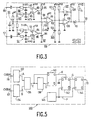
- Fig. 3 shows a comparison device adapted to compare the luminance signal components of two received picture signals and suitable for use in a video recorder of the video system shown in Fig. 1.
- Fig. 3 shows a comparison device adapted to compare the luminance signal components of two received picture signals and suitable for use in a video recorder of the video system shown in Fig. 1.
- Fig. 4 shows in its parts A, B, C, D, E, F, G and H waveform diagrams of signals in the comparison device shown in Fig. 3.
- Fig. 5 shows a comparison device of a video recorder in accordance with a further embodiment of the invention, which device is adapted to compare the synchronising signals derived from the received picture signal supplied by the tuner of the video recorder and from the received picture signal supplied by the tuner of a television receiver connected to the video recorder.
- Fig. 1 shows a video system 1 comprising a video recorder 2 in accordance with a first embodiment of the invention and a television receiver 3.
- the video recorder 2 and the television receiver 3 each comprise a connector, 4 and 5 respectively, usually referred to as a SCART socket.
- the two connectors 4 and 5 are interconnected by a multi-core cabling 6, of which five cores or lines 7, 8, 9, 10 and 11 are shown.
- the cabling 6 serves for the signal transmission between the video recorder 2 and the television receiver 3, the transmission from the television receiver 3 to the video recorder 2 being possible via the line 7 for picture signals received and demodulated by the television receiver 3 and via the line 8 for sound signals received and demodulated by the television receiver 3.
- Further signals can be transmitted either from the television receiver 3 to the video recorder 2 or, conversely, from the video recorder 2 to the television receiver 3 via the other lines 9, 10 and 11 and further lines, not shown.
- a further transmission line 12 between the video recorder 2 and the television receiver 3 serves for transmitting non-demodulated television signals and is connected to a socket 13 of the video recorder 2 and to a socket 14 of the television receiver 3.
- the socket 13 of the video recorder 2 is connected to a socket 16 of the video recorder 2 via a so-called loop-through line 15 of the video recorder 2.
- the socket 16 serves for the connection of a receiving aerial 17, a satellite television receiving device 18, shown diagrammatically in Fig. 1, or a cable television receiving device, not shown in Fig. 1.
- the video recorder 2 has an electronically tunable tuner 19 whose television signal input 20 is connected to the socket 16.
- the tuner 19 has a control input 21 to which control signals can be applied, which control signals can be generated and supplied by a control device 22 formed by a microcomputer 22.
- One of these control signals starts a successive tuning of the tuner 19 of the video recorder 2 to different stations and another one of these control signals causes the tuner 19 of the video recorder 2 to be locked to a previously tuned station.
- the tuner 19 of the video recorder 2 has a first output 23 and a second output 24. On the first output 23 the tuner 19 supplies a demodulated picture signal. On the second output 24 the tuner 19 supplies a demodulated sound signal.
- the first output 23 of the tuner 19 is connected to a recording picture signal processor 26, whose output 27 is connected to two rotatably drivable magnetic heads 28 and 29 of a drum-shaped scanning device 30.
- a magnetic tape 31 is wrapped around the drum-shaped scanning device 30 along a helical path through an angle of approximately 180°, so that the rotatably drivable magnetic heads 28 and 29 consecutively scan adjacent track portions which are inclined relative to the longitudinal direction of the magnetic tape 31, in which track portions the picture signals supplied by the recording picture signal processor 26 are recorded.
- the second output 24 of the tuner 19 is connected to an input 33 of a recording sound signal processor 34, whose output 35 is connected to a stationary magnetic head 36, which is also in scanning contact with the magnetic tape 31 and by means of which the sound signals supplied by the recording sound signal processor 34 can be recorded on the magnetic tape 31 in a sound signal track which extends in the longitudinal direction of the magnetic tape 31.
- a remote control device 37 having a set of keys 38 for the entry of remote-control commands.
- the remote control device 37 has further keys which are concealed by a cover, not shown, and which are consequently not visible in Fig. 1.
- the set of keys 38 of the remote control device 37 includes a key 39 by means of which a so-called "follow-me” command can be given, as will be described in detail hereinafter.
- the remote control device 37 comprises an infrared signal transmitter 40, which conveys the remote control commands generated in the remote control device 37 to an infrared signal receiver 41 of the video recorder 2 by means of infrared signals.
- the infrared signal receiver 41 forms part of an infrared signal processor 42, which processes the received infrared signals and which supplies data corresponding to the received remote control commands to the microcomputer 22 via a data connection 43, represented as a single line in Fig. 1.
- the microcomputer 22 processes the data corresponding to the received remote control commands and produces on its control outputs 44 control commands which control the units of the video recorder necessary to perform the mode or function corresponding to the received remote control command.
- the microcomputer 22 also has a plurality of further control inputs 45 via which further control signals can be applied to the microcomputer 22.
- the television receiver 3 also has a tuner 46 whose television signal input 47 is connected to the socket 14, so that the television signal received by means of, for example, a television aerial 17 can be applied to the socket 14 via the socket 16, the loop-through line 15, the socket 13 and the transmission line 12 and hence to the tuner 46 of the television receiver 3 via the input 47.
- the tuner 46 of the television receiver 3 is also electronically tunable and for this purpose it has a control input 48 to which control signals generated by a control device 49 formed by a microcomputer 49 can be applied to tune the tuner 46 of the television receiver 3 successively to different stations and to keep it tuned to a station.
- the tuner 46 of the television receiver 3 has a first output 50 and second output 51. On the first output 50 the tuner 49 supplies a demodulated television signal. On the second output 51 the tuner 46 supplies a demodulated sound signal.
- the first output 50 of the tuner 49 of the television receiver 3 is connected to the input 52 of a television signal processor 53 which supplies on its outputs 54, of which three outputs are shown in Fig. 1, signals for driving a picture tube 55 of the television receiver 3, which signals are applied to the picture tube 55 via lines 56.
- the second output 51 of the tuner 46 of the television receiver 3 is connected to an input 57 of a sound signal processor 58 whose output 59 is connected to a loudspeaker 60 which acoustically reproduces the sound signals supplied by the sound signal processor 58.
- the first output 50 of the tuner 46 of the television receiver 3 is further connected to a terminal 61 of the connector 5 of the television receiver 3, which terminal is connected to a contact 62 of the connector 4 of the video recorder 2 via the line 7 of the cabling 6.
- the second output 51 of the tuner 46 is further connected to a contact 63 of the connector 5 of the television receiver 3, which contact is connected to a contact 64 of the connector 4 of the video recorder 2 via the line 8 of the cabling 6.
- the first output 23 of the tuner 19 of the video recorder 2 is connected to an input 67 of a comparison device 69 of the video recorder 2 via a line 65 and the contact 62 of the connector 4 of the video recorder 2 is connected to an input 68 of this comparison device via a line 66.
- the comparison device 69 of the video recorder 2 serves for comparing at least one component of the received picture signal supplied by the tuner 46 of the television receiver 3 to the connector 4 of the video recorder 2 with the corresponding component of the received picture signal supplied by the tuner 19 of the video recorder 2.
- the comparison device 69 is adapted to compare the luminance signal component Y-TV of the picture signal supplied by the tuner 46 of the television receiver 3 with the luminance signal component Y-VR of the picture signal supplied by the tuner 19 of the video recorder 2, which will be described in more detail with reference to Figures 3 and 4.
- the comparison device 69 is constructed to supply an inequality signal S1 in the case of inequality of the two received picture signals applied to it, and to supply an equality signal S2 in the case of equality of the two received signals applied to it.
- the inequality signal S1 and the equality signal S2 appear on an output 70 of the comparison device 69.
- a comparison device 69 may have two separate outputs to supply the inequality signal and the equality signal, respectively.
- the output 70 of the comparison device 69 is connected to a control input 71 of the microcomputer 22.
- the microcomputer 22 detects the presence of the inequality signal S1 or the equality signal S2. If the microcomputer 22 detects an inequality signal S1 the microcomputer 22 produces on a control output 72, which is connected to the control input 21 of the tuner 19 of the video recorder 2, a control signal which causes the tuner 19 of the video recorder 2 to be successively tuned to different stations.
- microcomputer 22 If the microcomputer 22 detects an equality signal S2 the microcomputer 22 produces on its control output 72 a control signal which is applied to the control input 21 of the tuner 19 of the video recorder 2 and which keeps the tuner 19 of the video recorder 2 tuned to a previously selected station.
- the tuner 46 of the television receiver 3 and the tuner 19 of the video recorder 2 are very often tuned to different stations broadcasting different programs, i.e. different program signals.
- a user of the video system 1 wishes to tune the tuner 19 of the video recorder 2 accurately and rapidly to the same station as the tuner 46 of the television receiver 3, for example to record the television program watched by the user on the television receiver 3 by means of the video recorder 2 without any significant delay.
- the user of the video system 1 shown in Fig. 1 merely has to actuate the "Follow me" key 39 on the remote control device 37 for the video recorder 2.
- a corresponding remote control command is transmitted to the infrared signal processor 42, which supplies a corresponding control signal to the microcomputer 22 via the connection 43, causing the microcomputer 22 to produce on its control output 72 a control signal, which is applied to the control input 21 of the tuner 19 of the video recorder 2 and which causes the tuner 19 of the video recorder 2 to be successively tuned to different stations.
- the tuner 19 supplies the picture signal produced on its first output 23 to the first input 67 of the comparison device 69 via the line 65, the picture signal supplied by the tuner 46 of the television receiver 3 being applied to the second input 68 of this device.
- the comparison device 69 produces on its output 70 an inequality signal S1, which is applied to the control input 71 of the microcomputer 22.
- the microcomputer 22 In response to the inequality signal S1 applied to it the microcomputer 22 generates a control signal on its control output 72, which signal is applied to the control input 21 of the tuner 19 of the video recorder 2 and which, in the same way as the control signal caused by actuation of the "Follow me” key 39 of the remote control device 37, results in the tuner 19 of the video recorder 2 being successively tuned to different stations.
- the television signals applied to the two inputs 67 and 68 of the comparison device 69 will be equal, as a result of which the comparison device 69 produces an equality signal S2 on its output 70, which signal is applied to the control input 71 of the microcomputer 22.
- the microcomputer 22 produces a control signal on its control output 72, which control signal is applied to the control input 21 of the tuner 19 of the video recorder 2 and keeps the tuner 19 of the video recorder 2 tuned to the station just tuned in to.
- the "Follow me" key 39 of the remote control device 37 may be actuated to start another station search, in which for example the characteristic station data stored in a memory of the microcomputer 22 are successively applied to the tuner 19 of the video recorder 2, as a result of which the tuner 19 is tuned to different stations at short time intervals on the basis of the characteristic data applied to this tuner.
- Such a station search can substantially speed up the location of a station to which the tuner 46 of the television receiver 3 is tuned.
- the microcomputer 22 can subsequently automatically start a station search in the tuner 19 of the video recorder 2, in which case it is ensured that a station is found which transmits the same program signal as the station to which the tuner 46 of the television receiver 3 is tuned.
- the characteristic data corresponding to this station may also be stored in the memory provided for this purpose in the microcomputer 22 of the video recorder 2.
- the tuner 19 of the video recorder 2 can be tuned very simply and, normally, also very rapidly to a station which transmits the same television program as the station to which the tuner 46 of the television receiver 3 is tuned.
- Fig. 2 shows a video system 1 which includes a video recorder 2 in accordance with a second embodiment of the invention.
- the first output 23 of the tuner 19 of the video recorder 2 is connected to the first input 67 of a first comparison device 69 via the line 65, and the contact 62, which is connected to the first output 50 of the tuner 46 of the television receiver 3 via the line 7 of the cabling 6, is connected to the second input 68 of the first comparison device 69 via the line 66.
- the first comparison device 69 is formed by a correlation device, which compares the received demodulated picture signals applied to its two inputs 67 and 68 with one another by means of a correlation technique.
- the construction of the first comparison device 69 as a correlation device has the advantage that owing to the use of the correlation technique the comparison of the two signals to be compared is substantially independent of the amplitudes and phase relationships of the signals to be compared. In the case of inequality of the signals which are compared with one another the first correlation device 69 produces an inequality signal on an output 70, whereas in the case of equality of the signals which are compared with one another the first correlation device 69 produces an equality signal on its output 70.
- the second output 24 of the tuner 19 is connected to a first input 74 of a second comparison device 75 via a line 73.
- a second input 76 of the second comparison device 75 is connected to the contact 64 of the connector 4 of the video recorder 2 via a line 77.
- the contact 64 is connected to the contact 63 of the connector 5 of the television receiver 3 via the line 8 of the cabling 6, which contact 63 is connected to the second output 51 of the tuner 46 of the television receiver 3.
- the second comparison device 75 is also formed by a correlation device, which has the advantage that also during the comparison of the demodulated sound signals a comparatively great independence of the amplitudes and phase relationships of the sound signals to be compared is achieved.
- this device produces an inequality signal on an output 78
- this device produces an equality signal on its output 78.
- the output of the first comparison device 69 and the output of the second comparison device 75 are connected to the inputs 79 and 80 of an AND gate 81, whose output 82 is connected to the control input 71 of the microcomputer 22.
- the AND gate 81 will also produce an inequality signal on its output 82, which signal is processed in the microcomputer 22, which produces on its control output 72 a control signal which is applied to the control input 21 of the tuner 19 of the video recorder 2, as a result of which the tuner 19 of the video recorder 2 is successively tuned to different stations.
- the two comparison devices 69 and 75 will each supply an equality signal, as a result of which the AND gate 61 also supplies an equality signal, which is applied to the microcomputer 22. Subsequently, the microcomputer 22 generates a corresponding control signal, which is applied to the tuner 19 of the video recorder 2 and which ensures that the tuner 19 of the video recorder 2 remains tuned to the station to which it has just been tuned.
- Fig. 3 shows a comparison device 69 suitable for use in a video recorder 2 of a video system 1 shown in Fig. 1.
- the comparison device 69 comprises two comparator stages 83 and 84, which are each formed by a differential amplifier having a so-called "open-collector" output, 85 and 86 respectively.
- the inverting input 87 of the first differential amplifier 83 is preceded by a low-pass filter 88 comprising a resistor and a capacitor and having a comparatively large time constant.
- the low-pass filter 88 extracts the luminance signal component Y-TV from the picture signal supplied by the tuner 46 of the television receiver 3 and applied to the second input 68 of the comparison device 69 and forms the average value Y-M1 of the luminance signal component Y-TV, which average value Y-M1 appears on the inverting input 87 of the differential amplifier 83 as a threshold value.
- the non-inverting input 89 of the first differential amplifier 83 is preceded by a low-pass filter comprising a resistor and a capacitor and having a comparatively small time constant, which filter extracts the luminance signal component Y-TV from the picture signal applied to the second input 68 and applies it to the non-inverting input 89 of the first differential amplifier 83.
- Part A of Fig. 4 by way of example shows two waveforms of the luminance signal component Y-TV and the average value Y-M1 of this luminance signal component Y-TV.
- the non-inverting input 91 of the second differential amplifier 84 is preceded by a low-pass filter 88 comprising a resistor and a capacitor and having a comparatively large time constant, which filter extracts the luminance signal component Y-VR from the picture signal supplied by the tuner 19 of the video recorder 2 and applied to the first input 67 of the comparison device 69 and forms an average value Y-M2 of the extracted luminance signal component Y-VR, which average value Y-M2 appears on the non-inverting input 91 of the second differential amplifier 84 as a threshold value.
- a low-pass filter 88 comprising a resistor and a capacitor and having a comparatively large time constant
- the inverting input 93 of the second differential amplifier 84 is preceded by a low-pass filter 94 comprising a resistor and a capacitor and having a comparatively small time constant, which filter extracts the luminance signal component Y-VR from the picture signal applied to the first input 67 and applies it to the inverting input 93 of the second differential amplifier 84.
- Part B of Fig. 4 by way of example shows two waveforms of the luminance signal component Y-VR and the corresponding average value Y-M2.
- the waveform of the luminance signal component Y-VR shown at the left in part B of the Figure differs from the waveform of the luminance signal component Y-TV shown at the left in part A of the Figure.
- the waveform of the luminance signal component Y-VR shown at the right in part B of the Figure corresponds to the waveform of the luminance signal component Y-TV shown at the right in part A of the Figure.
- the two differential amplifiers 83 and 84 compare the relevant luminance signal component Y-TV or Y-VR with the respective average value Y-M1 or Y-M2. This comparison results in the pulse-shaped signal shown in part C of Fig. 4 appearing on the output 85 of the first differential amplifier 83. As is shown, a pulse-shaped signal will appear on the output 85 each time that the amplitude of the luminance signal component exceeds the average value. The pulse-shaped signal shown in part D of Fig. 4 appears on the output 86 of the second differential amplifier 84. As is shown, a pulse-shaped signal will appear on the output 86 each time that the luminance signal component Y-VR exceeds the average value.
- the behaviour of the pulse-shaped signal on the output 86 of the second differential amplifier 84 is the inverse of that of the pulse-shaped signal on the output 85 of the first differential amplifier 83, which is because the luminance signal component Y-TV is applied to the non-inverting input 89 and the luminance signal component Y-VR to the inverting input 93 and the average value Y-M1 is applied to the inverting input 87 and the average value Y-M2 to the non-inverting input 91.
- the outputs 85 and 86 of the two differential amplifiers 83 and 84 are directly coupled to one another and their common node is situated between a resistor 95 and a capacitor 96, which together form an integrating network 97.
- This combined output signal is integrated by the integrating network 97, yielding the signal shown in part F of Fig. 4.
- the signal shown in part F of Fig. 4 is applied to an inverting input 98 of a further differential amplifier 99 forming a comparator stage, whose non-inverting input 100 receives a reference voltage U-Ref formed by means of a voltage divider 101.
- the further differential amplifier 99 the two input signals are compared, the signal shown in part G of Fig. 4 being obtained on the output 102 of the further differential amplifier.
- the signal produced on the output 102 of the differential amplifier 99 is applied to a further integrating network 105 formed by a resistor 103 and a capacitor 104 and having a very large time constant.
- the potential across the capacitor 104 is applied to a Schmitt trigger 107 formed by means of a further differential amplifier 106.
- the output transistor, not shown, of the differential amplifier 106 which transistor is disposed between the "open-collector" output 108 of the differential amplifier 106 and earth, is cut off so that, via a resistor 109, the potential +V1 appears on the output 108, which potential is isolated from the output 70 of the comparison device 69 by a diode 110, as a result of which the potential +V2 is obtained on the output 70 via a resistor 111, which potential forms the inequality signal S1 shown at the left in part H of Fig. 4 and can be applied directly to the microcomputer 22.
- the output transistor, not shown, of the differential amplifier 106 which transistor is disposed between the "open-collector" output 108 of the differential amplifier 106 and earth, is turned on so that the output 108 of the differential amplifier is pulled to earth, resulting in a current via the resistor 111, the diode 110 and the output transistor, not shown, of the differential amplifier 106, resulting in a potential relative to earth which corresponds to the voltage drop across the conductive diode 110, which potential forms the equality signal S2 shown at the right in part H of Fig. 4 and can be applied directly to the microcomputer 22.
- the comparison device described with reference to Fig. 3 is merely one possibility of implementing such a comparison device.
- to detect the equality of two picture signals it is also possible to compare the colour signal components of these two picture signals.
- Fig. 5 shows a further variant of a comparison device bearing the reference numeral 130.
- the comparison device 130 comprises two sync separators 132 and 134, which each have an input coupled to one of the respective inputs 68 or 67 of the comparison device 130.
- the outputs of the sync separators 132 and 134 are coupled to inputs of an EXCLUSIVE OR gate 136.
- the output of the EXCLUSIVE OR gate 136 is coupled to an input of a monostable multivibrator 138 and to the D input of a first D flip-flop circuit 140.
- the output of the multivibrator 138 is coupled to the clock input T of the first D flip-flop circuit 140.
- the Q output of the first D flip-flop circuit 140 is coupled to the set input S of a second D flip-flop circuit 142, whose D input is coupled to a point of constant potential, in the present case earth potential.
- the Q output of the second D flip-flop circuit 142 is coupled to the D output of a third D flip-flop circuit 144, whose Q output is coupled to the output 70 of the comparison device 130.
- the comparison device 130 further includes a generator 146 having an output on which pulses F having a repetition frequency of, for example, 50 Hz are produced, which output is coupled to the clock inputs T of the second D flip-flop circuit 142 and the third D flip-flop circuit 144.
- the picture signals are in synchronism. Slight differences in timing may occur because the two tuners 19 and 46 have different IF filters, which are for example formed by means of coils and capacitors or which operate with acoustic surface wave devices. However, the resulting time differences are smaller than 1 ⁇ s.
- the synchronisation signals A and B derived from the two picture signals CVBS-1 and CVBS-2 by the two sync separators 132 and 134 are applied to the EXCLUSIVE OR gate 136.
- This EXCLUSIVE OR gate 136 formes a pulse-shaped difference signal C.
- the difference signal C has a high level "H” in the case of a difference between the synchronisation signals A and B. If the synchronisation signals A and B originate from the same transmitter the difference signal C has a substantially low level "C” and this difference signal C will at the most exhibit short pulses having a high level "H” and a duration smaller than 1 ⁇ m.
- the monostable multivibrator 138 On every rising edge of the pulse-shaped difference signal C the monostable multivibrator 138 is started and forms a pulse D having a high level "H" and a length of 1 ⁇ s.
- the trailing edge of a pulse D occurs the trailing edge of the difference signal C has already ended, i.e. the difference signal C again exhibits a low level "L” if the synchronisation signals A and B stem from the same transmitter.
- the first D flip-flop circuit 140 always generates a signal with a low level "L", so that the output signal E remains at a low level "L".
- the first D flip-flop circuit 140 will supply a signal with a high level "H” and the output signal E will assume a high level "H".
- An output signal with a high level "H” from the first D flip-flop circuit 140 results in a signal with a high level "H” on the Q output of the second D flip-flop circuit 142, regardless of the signals on the T input and the D input of the second D flip-flop circuit 142.
- the generator 146 produces 50 times per second a signal with a low level "L” in the second D flip-flop circuit 142.
- the output signal G on the Q output of the second D flip-flop circuit 142 is transferred as an input signal G to the D input of the third D flip-flop circuit 144 at each clocking instant.
- the signal on the output 70 of the comparison device 130 only has a low level "L” if the synchronisation signals A and B, i.e . the horizontal as well as the vertical synchronisation signals, are synchronous within 1 ⁇ s.
- This signal with a low level "L” represents the equality signal of this comparison device 130, which signal is used in the video recorder 2 to keep the tuner 19 of the video recorder 2 at a previously selected station. If the synchronisation signals A and B are not in synchronism the signal on the output 70 of the comparison device 130, as already stated, will have a high level "H". This signal indicates that there is no synchronism.
- circuit arrangement shown in Fig. 5 does not function if the sync separators 132 and 134 no longer supply synchronisation signals A and B. This may happen if the television station to be received is no longer transmitting. For this situation a separate protection device may be provided.
- the generator 146 need not necessarily generate pulses having a pulse repetition frequency of 50 Hz.
- a generator generating pulses with a pulse repetition frequency of 60 Hz it is advantageous to use, for example, a generator generating pulses with a pulse repetition frequency of 60 Hz.
- the pulse repetition frequency of the pulse-shaped generator signal produced by the generator 146 should be selected in such a manner that at least one field synchronisation signal occurs within one period of the generator signal.
- the monostable multivibrator 138 may also be constructed to supply pulses of a pulse duration which differs from 1 ⁇ s, so that the comparison accuracy can be adapted to different requirements.
Claims (5)
- Videorecorder mit einem elektronisch abstimmbaren Tuner, der auf einen Sender aus einer Mehrzahl von verschiedenen Sendern abstimmbar ist und der nach seiner Abstimmung auf einen Sender ein empfangenes Bildsignal und ein empfangenes Tonsignal abgibt, und mit einer Anschlußeinrichtung, an die eine Kabelverbindung anschließbar ist, die an eine Anschlußeinrichtung eines Fernsehempfängers anschließbar ist, der ebenfalls einen Tuner aufweist, der auf einen Sender aus einer Mehrzahl von verschiedenen Sendern abstimmbar ist und der nach seiner Abstimmung auf einen Sender ein empfangenes Bildsignal und ein empfangenes Tonsignal abgibt, welche empfangenen Signale beide über die Kabelverbindung dem Videorecorder zuführbar sind, dadurch gekennzeichnet, daß mit dem Tuner des Videorecorders und mit der genannten Anschlußeinrichtung des Videorecorders mindestens eine Vergleichseinrichtung des Videorecorders zum Vergleichen von zumindest einem Anteil eines der beiden genannten, von dem Tuner des Fernsehempfängers abgegebenen, dem Videorecorder zugeführten, empfangenen Signale mit dem korrespondierenden Anteil des vom Tuner des Videorecorders abgegebenen empfangenen Signals verbunden ist, daß eine solche Vergleichseinrichtung zum Abgeben eines Ungleichheitssignals bei Ungleichheit der beiden ihr zugeführten empfangenen Signale und zum Abgeben eines Gleichheitssignals bei Gleichheit der beiden ihr zugeführten empfangenen Signale ausgebildet ist und daß der Tuner des Videorecorders aufeinanderfolgend auf verschiedene Sender abgestimmt wird, wenn eine solche Vergleichseinrichtung ein Ungleichheitssignal abgibt, und der Tuner des Videorecorders auf einen Sender abgestimmt gehalten wird, wenn eine solche Vergleichseinrichtung ein Gleichheitssignal abgibt.
- Videorecorder nach Anspruch 1, dadurch gekennzeichnet, daß dieser Vergleichseinrichtung das vom Tuner des Fernsehempfängers abgegebene und dem Videorecorder zugeführte empfangene Bildsignal und das vom Tuner des Videorecorders abgegebene empfangene Bildsignal zugeführt werden und daß die Vergleichseinrichtung zum Vergleichen der Helligkeitssignalanteile der zwei Bildsignale ausgebildet ist.
- Videorecorder nach Anspruch 1 oder 2, dadurch gekennzeichnet, daß dieser Vergleichseinrichtung das vom Tuner des Fernsehempfängers abgegebene und dem Videorecorder an dessen Anschlußeinrichtung zugeführte empfangene Tonsignal und das vom Tuner des Videorecorders abgegebene empfangene Tonsignal zugeführt werden und daß die Vergleichseinrichtung zum Vergleichen der zwei Tonsignale ausgebildet ist.
- Videorecorder nach Anspruch 1, 2 oder 3, dadurch gekennzeichnet, daß Einrichtungen zum Ableiten von Synchronsignalen aus dem vom Tuner des Fernsehempfängers abgegebenen empfangenen Bildsignal und dem vom Tuner des Videorecorders abgegebenen empfangenen Bildsignal vorgesehen sind und daß die Vergleichseinrichtung zum Vergleichen der aus den zwei Bildsignalen abgeleiteten Synchronsignale ausgebildet ist.
- Videorecorder nach Anspruch 1, 2, 3 oder 4, dadurch gekennzeichnet, daß eine solche Vergleichseinrichtung durch eine Korrelationseinrichtung gebildet ist.
Applications Claiming Priority (2)
| Application Number | Priority Date | Filing Date | Title |
|---|---|---|---|
| AT67493 | 1993-04-01 | ||
| AT674/93 | 1993-04-01 |
Publications (3)
| Publication Number | Publication Date |
|---|---|
| EP0618721A2 EP0618721A2 (de) | 1994-10-05 |
| EP0618721A3 EP0618721A3 (de) | 1995-03-01 |
| EP0618721B1 true EP0618721B1 (de) | 1998-08-05 |
Family
ID=3496840
Family Applications (1)
| Application Number | Title | Priority Date | Filing Date |
|---|---|---|---|
| EP94200859A Expired - Lifetime EP0618721B1 (de) | 1993-04-01 | 1994-03-29 | Videorekorder |
Country Status (7)
| Country | Link |
|---|---|
| US (1) | US5631995A (de) |
| EP (1) | EP0618721B1 (de) |
| JP (1) | JP3429839B2 (de) |
| KR (1) | KR100287604B1 (de) |
| AT (1) | ATE169441T1 (de) |
| DE (1) | DE69412160T2 (de) |
| ES (1) | ES2122143T3 (de) |
Families Citing this family (120)
| Publication number | Priority date | Publication date | Assignee | Title |
|---|---|---|---|---|
| US8352400B2 (en) | 1991-12-23 | 2013-01-08 | Hoffberg Steven M | Adaptive pattern recognition based controller apparatus and method and human-factored interface therefore |
| AU6352894A (en) | 1993-03-05 | 1994-09-26 | Roy J. Mankovitz | Apparatus and method using compressed codes for television program record scheduling |
| US6239794B1 (en) | 1994-08-31 | 2001-05-29 | E Guide, Inc. | Method and system for simultaneously displaying a television program and information about the program |
| JPH0787411A (ja) * | 1993-08-26 | 1995-03-31 | Gold Star Co Ltd | Tvとvcrのチャンネル自動切換装置及びチャンネル自動切換方法 |
| US8793738B2 (en) | 1994-05-04 | 2014-07-29 | Starsight Telecast Incorporated | Television system with downloadable features |
| FR2726719B1 (fr) * | 1994-11-04 | 1996-11-29 | Thomson Consumer Electronics | Appareil de reception video et procede d'asservissement de recepteurs |
| KR0141741B1 (ko) * | 1995-04-21 | 1998-07-15 | 구자홍 | 브이씨알의 자동 녹화장치 |
| US6769128B1 (en) | 1995-06-07 | 2004-07-27 | United Video Properties, Inc. | Electronic television program guide schedule system and method with data feed access |
| US6388714B1 (en) | 1995-10-02 | 2002-05-14 | Starsight Telecast Inc | Interactive computer system for providing television schedule information |
| US6323911B1 (en) | 1995-10-02 | 2001-11-27 | Starsight Telecast, Inc. | System and method for using television schedule information |
| US6732369B1 (en) | 1995-10-02 | 2004-05-04 | Starsight Telecast, Inc. | Systems and methods for contextually linking television program information |
| KR970063234A (ko) * | 1996-02-27 | 1997-09-12 | 김광호 | 1튜너를 채용한 tvcr에서의 녹화중 다른 채널 확인방법 |
| KR19990021900A (ko) * | 1996-03-27 | 1999-03-25 | 엠. 제이. 엠. 반캄 | 제어 데이타의 방송 수신기로의 다운로딩 |
| US6469753B1 (en) | 1996-05-03 | 2002-10-22 | Starsight Telecast, Inc. | Information system |
| US5801787A (en) * | 1996-06-14 | 1998-09-01 | Starsight Telecast, Inc. | Television schedule system and method of operation for multiple program occurrences |
| KR100200609B1 (ko) * | 1996-07-30 | 1999-06-15 | 윤종용 | 2튜너 시스템에서의 kbps 예약 녹화 장치 및 방법 |
| WO1998010589A1 (en) * | 1996-09-03 | 1998-03-12 | Starsight Telecast, Inc. | Schedule system with enhanced recording capability |
| US20030005463A1 (en) * | 1999-09-30 | 2003-01-02 | Douglas B Macrae | Access to internet data through a television system |
| US20030066085A1 (en) * | 1996-12-10 | 2003-04-03 | United Video Properties, Inc., A Corporation Of Delaware | Internet television program guide system |
| US6687906B1 (en) | 1996-12-19 | 2004-02-03 | Index Systems, Inc. | EPG with advertising inserts |
| US8635649B2 (en) | 1996-12-19 | 2014-01-21 | Gemstar Development Corporation | System and method for modifying advertisement responsive to EPG information |
| BRPI9812104B1 (pt) | 1997-07-21 | 2016-12-27 | Guide E Inc | método para navegar por um guia de programa interativo |
| US6141488A (en) * | 1997-09-05 | 2000-10-31 | United Video Properties, Inc. | Program guide system for recording television programs |
| ATE217744T1 (de) | 1997-09-18 | 2002-06-15 | United Video Properties Inc | Erinnerungsvorrichtung für internet- fernsehprogrammführer mittels elektronischer post |
| US6604240B2 (en) | 1997-10-06 | 2003-08-05 | United Video Properties, Inc. | Interactive television program guide system with operator showcase |
| JP3365298B2 (ja) * | 1998-02-27 | 2003-01-08 | 松下電器産業株式会社 | 映像信号録画再生装置 |
| US7185355B1 (en) | 1998-03-04 | 2007-02-27 | United Video Properties, Inc. | Program guide system with preference profiles |
| US6564379B1 (en) | 1998-04-30 | 2003-05-13 | United Video Properties, Inc. | Program guide system with flip and browse advertisements |
| US6742183B1 (en) | 1998-05-15 | 2004-05-25 | United Video Properties, Inc. | Systems and methods for advertising television networks, channels, and programs |
| US20020095676A1 (en) | 1998-05-15 | 2002-07-18 | Robert A. Knee | Interactive television program guide system for determining user values for demographic categories |
| US6442755B1 (en) | 1998-07-07 | 2002-08-27 | United Video Properties, Inc. | Electronic program guide using markup language |
| CN1867068A (zh) | 1998-07-14 | 2006-11-22 | 联合视频制品公司 | 交互式电视节目导视系统及其方法 |
| AR020608A1 (es) | 1998-07-17 | 2002-05-22 | United Video Properties Inc | Un metodo y una disposicion para suministrar a un usuario acceso remoto a una guia de programacion interactiva por un enlace de acceso remoto |
| CN101383947B (zh) | 1998-07-17 | 2012-08-01 | 联合视频制品公司 | 通过远程访问链接访问节目和提供节目的方法 |
| US6505348B1 (en) * | 1998-07-29 | 2003-01-07 | Starsight Telecast, Inc. | Multiple interactive electronic program guide system and methods |
| US6898762B2 (en) | 1998-08-21 | 2005-05-24 | United Video Properties, Inc. | Client-server electronic program guide |
| US6865746B1 (en) | 1998-12-03 | 2005-03-08 | United Video Properties, Inc. | Electronic program guide with related-program search feature |
| US6792197B1 (en) * | 1998-12-07 | 2004-09-14 | Index Systems, Inc. | System and method for generating video taping reminders |
| US7966078B2 (en) | 1999-02-01 | 2011-06-21 | Steven Hoffberg | Network media appliance system and method |
| MXPA01013446A (es) | 1999-06-28 | 2002-08-06 | Index Systems Inc | Sistema y metodo para utilizar bases de datos de guia electronica de programas para modificar anuncios. |
| AU5775900A (en) | 1999-06-29 | 2001-01-31 | United Video Properties, Inc. | Method and system for a video-on-demand-related interactive display within an interactive television application |
| WO2001046869A2 (en) | 1999-12-10 | 2001-06-28 | United Video Properties, Inc. | Systems and methods for coordinating interactive and passive advertisement and merchandising opportunities |
| BR0108012A (pt) * | 2000-02-01 | 2006-02-07 | United Video Properties Inc | Sistemas e métodos para a provisão de promoções com programas gravados |
| ATE477677T1 (de) | 2000-02-01 | 2010-08-15 | United Video Properties Inc | Methoden und systeme zum erzwingen von reklame |
| AU5005601A (en) | 2000-03-31 | 2001-10-15 | United Video Properties Inc | Systems and methods for reducing cut-offs in program recording |
| JP2003529844A (ja) | 2000-03-31 | 2003-10-07 | ユナイテッド ビデオ プロパティーズ, インコーポレイテッド | メタデータによってリンクされた宣伝のシステムおよび方法 |
| KR20190096450A (ko) | 2000-10-11 | 2019-08-19 | 로비 가이드스, 인크. | 매체 콘텐츠 배달 시스템 및 방법 |
| EP1936982A3 (de) * | 2001-02-21 | 2010-12-15 | United Video Properties, Inc. | Systeme und methoden für interaktive programmführung mit persönlichen Videoaufnahmemerkmalen |
| US8156528B2 (en) * | 2001-03-22 | 2012-04-10 | United Video Properties, Inc. | Personal video recorder systems and methods |
| AU2002360441A1 (en) * | 2001-11-26 | 2003-06-10 | United Video Properties, Inc. | Interactive television program guide for recording enhanced video content |
| US7774816B2 (en) * | 2002-04-23 | 2010-08-10 | Rovi Technologies Corporation | Conflict manager for a video recorder |
| AU2003243183A1 (en) * | 2002-05-01 | 2003-11-17 | Index Systems, Inc. | Method and system for facilitating advertising and t-commerce transactions in connection with content stored on a storage medium |
| US20040103434A1 (en) | 2002-11-25 | 2004-05-27 | United Video Properties, Inc. | Interactive television systems with conflict management capabilities |
| US7493646B2 (en) | 2003-01-30 | 2009-02-17 | United Video Properties, Inc. | Interactive television systems with digital video recording and adjustable reminders |
| US8116611B2 (en) * | 2003-02-10 | 2012-02-14 | Aptiv Digital, Inc. | Tuner sharing video recorder system architecture |
| US6760538B1 (en) | 2003-04-21 | 2004-07-06 | Pioneer Digital Technologies, Inc. | Video recorder having user extended and automatically extended time slots |
| US20060051059A1 (en) * | 2004-09-08 | 2006-03-09 | Krakirian Haig H | Video recorder having user extended and automatically extended time slots |
| US20040213557A1 (en) * | 2003-04-23 | 2004-10-28 | Pioneer Digital Technologies, Inc. | Non-hierarchical interface screens for use in a video recorder |
| WO2004099931A2 (en) * | 2003-05-05 | 2004-11-18 | Thomson Licensing S.A. | Method for tuning to an interconnected ieee-1394 compliant device |
| US8438601B2 (en) | 2003-07-02 | 2013-05-07 | Rovi Solutions Corporation | Resource management for a networked personal video recording system |
| US7454120B2 (en) * | 2003-07-02 | 2008-11-18 | Macrovision Corporation | Methods and apparatus for client aggregation of television programming in a networked personal video recording system |
| US7984468B2 (en) | 2003-11-06 | 2011-07-19 | United Video Properties, Inc. | Systems and methods for providing program suggestions in an interactive television program guide |
| US20050147247A1 (en) * | 2003-11-14 | 2005-07-07 | Westberg Thomas E. | Interactive television systems having POD modules and methods for use in the same |
| US20100153997A1 (en) * | 2004-01-21 | 2010-06-17 | United Video Properties, Inc. | Interactive television system with templates for managing vendor-specific video-on-demand content |
| US8806533B1 (en) | 2004-10-08 | 2014-08-12 | United Video Properties, Inc. | System and method for using television information codes |
| US20100311399A1 (en) * | 2005-03-31 | 2010-12-09 | United Video Properties, Inc. | Systems and methods for generating audible reminders on mobile user equipment |
| US8229283B2 (en) | 2005-04-01 | 2012-07-24 | Rovi Guides, Inc. | System and method for quality marking of a recording |
| US7788266B2 (en) | 2005-08-26 | 2010-08-31 | Veveo, Inc. | Method and system for processing ambiguous, multi-term search queries |
| US7646962B1 (en) | 2005-09-30 | 2010-01-12 | Guideworks, Llc | System and methods for recording and playing back programs having desirable recording attributes |
| US8582946B2 (en) | 2005-11-04 | 2013-11-12 | Rovi Guides, Inc. | Systems and methods for recording programs using a network recording device as supplemental storage |
| US9113107B2 (en) | 2005-11-08 | 2015-08-18 | Rovi Guides, Inc. | Interactive advertising and program promotion in an interactive television system |
| US9015736B2 (en) * | 2005-12-29 | 2015-04-21 | Rovi Guides, Inc. | Systems and methods for episode tracking in an interactive media environment |
| US20070157220A1 (en) * | 2005-12-29 | 2007-07-05 | United Video Properties, Inc. | Systems and methods for managing content |
| US8214869B2 (en) * | 2005-12-29 | 2012-07-03 | Rovi Guides, Inc. | Systems and methods for managing a status change of a multimedia asset in multimedia delivery systems |
| US20070157237A1 (en) * | 2005-12-29 | 2007-07-05 | Charles Cordray | Systems and methods for episode tracking in an interactive media environment |
| US7765235B2 (en) * | 2005-12-29 | 2010-07-27 | Rovi Guides, Inc. | Systems and methods for resolving conflicts and managing system resources in multimedia delivery systems |
| US20070156521A1 (en) | 2005-12-29 | 2007-07-05 | United Video Properties, Inc. | Systems and methods for commerce in media program related merchandise |
| US20070157242A1 (en) * | 2005-12-29 | 2007-07-05 | United Video Properties, Inc. | Systems and methods for managing content |
| US7774341B2 (en) | 2006-03-06 | 2010-08-10 | Veveo, Inc. | Methods and systems for selecting and presenting content based on dynamically identifying microgenres associated with the content |
| US8316394B2 (en) | 2006-03-24 | 2012-11-20 | United Video Properties, Inc. | Interactive media guidance application with intelligent navigation and display features |
| US20070245019A1 (en) * | 2006-04-12 | 2007-10-18 | United Video Properties, Inc. | Interactive media content delivery using a backchannel communications network |
| US20080046935A1 (en) * | 2006-08-18 | 2008-02-21 | Krakirian Haig H | System and method for displaying program guide information |
| US8832742B2 (en) | 2006-10-06 | 2014-09-09 | United Video Properties, Inc. | Systems and methods for acquiring, categorizing and delivering media in interactive media guidance applications |
| US8209424B2 (en) * | 2006-12-20 | 2012-06-26 | United Video Properties, Inc. | Systems and methods for providing remote access to interactive media guidance applications |
| US20080155600A1 (en) * | 2006-12-20 | 2008-06-26 | United Video Properties, Inc. | Systems and methods for providing remote access to interactive media guidance applications |
| US7801888B2 (en) | 2007-03-09 | 2010-09-21 | Microsoft Corporation | Media content search results ranked by popularity |
| US8418206B2 (en) | 2007-03-22 | 2013-04-09 | United Video Properties, Inc. | User defined rules for assigning destinations of content |
| US8087047B2 (en) | 2007-04-20 | 2011-12-27 | United Video Properties, Inc. | Systems and methods for providing remote access to interactive media guidance applications |
| US8107977B2 (en) | 2007-09-07 | 2012-01-31 | United Video Properties, Inc. | Cross-platform messaging |
| US8327403B1 (en) | 2007-09-07 | 2012-12-04 | United Video Properties, Inc. | Systems and methods for providing remote program ordering on a user device via a web server |
| US20090165051A1 (en) * | 2007-12-19 | 2009-06-25 | United Video Properties, Inc. | Methods and devices for presenting an interactive media guidance application |
| US20090165049A1 (en) * | 2007-12-19 | 2009-06-25 | United Video Properties, Inc. | Methods and devices for presenting and interactive media guidance application |
| US8252911B2 (en) * | 2008-02-12 | 2012-08-28 | Pacific Biosciences Of California, Inc. | Compositions and methods for use in analytical reactions |
| US8293714B2 (en) * | 2008-05-05 | 2012-10-23 | Covx Technology Ireland, Ltd. | Anti-angiogenic compounds |
| US8989561B1 (en) | 2008-05-29 | 2015-03-24 | Rovi Guides, Inc. | Systems and methods for alerting users of the postponed recording of programs |
| US8601526B2 (en) | 2008-06-13 | 2013-12-03 | United Video Properties, Inc. | Systems and methods for displaying media content and media guidance information |
| US8624908B1 (en) | 2008-06-27 | 2014-01-07 | Rovi Guides, Inc. | Systems and methods of transitioning from buffering video to recording video |
| US8959556B2 (en) * | 2008-09-29 | 2015-02-17 | The Nielsen Company (Us), Llc | Methods and apparatus for determining the operating state of audio-video devices |
| US10063934B2 (en) | 2008-11-25 | 2018-08-28 | Rovi Technologies Corporation | Reducing unicast session duration with restart TV |
| US20100262931A1 (en) * | 2009-04-10 | 2010-10-14 | Rovi Technologies Corporation | Systems and methods for searching a media guidance application with multiple perspective views |
| US20100306708A1 (en) * | 2009-05-29 | 2010-12-02 | Rovi Techonologies Corporation | Systems and methods for handling profiles in a community |
| US20110016492A1 (en) * | 2009-07-16 | 2011-01-20 | Gemstar Development Corporation | Systems and methods for forwarding media asset events |
| US9166714B2 (en) | 2009-09-11 | 2015-10-20 | Veveo, Inc. | Method of and system for presenting enriched video viewing analytics |
| US9014546B2 (en) | 2009-09-23 | 2015-04-21 | Rovi Guides, Inc. | Systems and methods for automatically detecting users within detection regions of media devices |
| US20110070819A1 (en) * | 2009-09-23 | 2011-03-24 | Rovi Technologies Corporation | Systems and methods for providing reminders associated with detected users |
| US8359616B2 (en) | 2009-09-30 | 2013-01-22 | United Video Properties, Inc. | Systems and methods for automatically generating advertisements using a media guidance application |
| US9201627B2 (en) * | 2010-01-05 | 2015-12-01 | Rovi Guides, Inc. | Systems and methods for transferring content between user equipment and a wireless communications device |
| US9204193B2 (en) | 2010-05-14 | 2015-12-01 | Rovi Guides, Inc. | Systems and methods for media detection and filtering using a parental control logging application |
| US9167196B2 (en) | 2010-05-19 | 2015-10-20 | Rovi Guides, Inc. | Systems and methods for trimming recorded content using a media guidance application |
| WO2012094564A1 (en) | 2011-01-06 | 2012-07-12 | Veveo, Inc. | Methods of and systems for content search based on environment sampling |
| US8949901B2 (en) | 2011-06-29 | 2015-02-03 | Rovi Guides, Inc. | Methods and systems for customizing viewing environment preferences in a viewing environment control application |
| US8805418B2 (en) | 2011-12-23 | 2014-08-12 | United Video Properties, Inc. | Methods and systems for performing actions based on location-based rules |
| US9218122B2 (en) | 2011-12-29 | 2015-12-22 | Rovi Guides, Inc. | Systems and methods for transferring settings across devices based on user gestures |
| US9692535B2 (en) | 2012-02-20 | 2017-06-27 | The Nielsen Company (Us), Llc | Methods and apparatus for automatic TV on/off detection |
| US9147198B2 (en) | 2013-01-10 | 2015-09-29 | Rovi Technologies Corporation | Systems and methods for providing an interface for data driven media placement |
| US9253262B2 (en) | 2013-01-24 | 2016-02-02 | Rovi Guides, Inc. | Systems and methods for connecting media devices through web sockets |
| US9848276B2 (en) | 2013-03-11 | 2017-12-19 | Rovi Guides, Inc. | Systems and methods for auto-configuring a user equipment device with content consumption material |
| US9674563B2 (en) | 2013-11-04 | 2017-06-06 | Rovi Guides, Inc. | Systems and methods for recommending content |
| US9264656B2 (en) | 2014-02-26 | 2016-02-16 | Rovi Guides, Inc. | Systems and methods for managing storage space |
| US9288521B2 (en) | 2014-05-28 | 2016-03-15 | Rovi Guides, Inc. | Systems and methods for updating media asset data based on pause point in the media asset |
Family Cites Families (12)
| Publication number | Priority date | Publication date | Assignee | Title |
|---|---|---|---|---|
| US2903508A (en) * | 1955-07-01 | 1959-09-08 | Rca Corp | Audience survey system |
| US3372233A (en) * | 1965-03-29 | 1968-03-05 | Nielsen A C Co | Horizontal and vertical sync signal comparison system |
| US3614625A (en) * | 1967-10-30 | 1971-10-19 | Itt | Master-slave, tuned channels for simultaneous tracking of plural signals of different frequencies |
| DE2454227C3 (de) * | 1974-11-15 | 1979-05-03 | Blaupunkt-Werke Gmbh, 3200 Hildesheim | Fernsehempfänger zum Empfang u. Auswerten von zusätzlichen Informationen in einem Fernsehsignal |
| US4291414A (en) * | 1979-05-02 | 1981-09-22 | Nippon Gakki Seizo Kabushiki Kaisha | Radio receiver operable in station search mode or station select mode |
| GB2126002A (en) * | 1982-08-25 | 1984-03-14 | Simon William Breese | Automatic control for recording apparatus |
| US4499601A (en) * | 1982-10-18 | 1985-02-12 | Matthews Gordon H | Method and apparatus for automatically detecting and playing desired audio segments over a broadcast receiver. |
| JPS6121695A (ja) * | 1984-07-10 | 1986-01-30 | Video Res:Kk | 視聴率測定システムにおけるビデオテ−プレコ−ダの動作状態検出方式 |
| DE3613796A1 (de) * | 1986-04-24 | 1987-10-29 | Grundig Emv | Ueberfuehrung von fernsehempfaenger-abstimmdaten in einen angeschlossenen videorecorder |
| EP0255107B1 (de) * | 1986-08-01 | 1994-04-20 | Sanyo Electric Co., Ltd. | Gerät zur Einstellung der Programmart |
| US4885632A (en) * | 1988-02-29 | 1989-12-05 | Agb Television Research | System and methods for monitoring TV viewing system including a VCR and/or a cable converter |
| JPH02283195A (ja) * | 1988-12-01 | 1990-11-20 | Matsushita Electric Ind Co Ltd | テレビ受像機およびビデオテープレコーダー装置 |
-
1994
- 1994-03-16 US US08/213,773 patent/US5631995A/en not_active Expired - Fee Related
- 1994-03-29 EP EP94200859A patent/EP0618721B1/de not_active Expired - Lifetime
- 1994-03-29 DE DE69412160T patent/DE69412160T2/de not_active Expired - Fee Related
- 1994-03-29 ES ES94200859T patent/ES2122143T3/es not_active Expired - Lifetime
- 1994-03-29 JP JP05878594A patent/JP3429839B2/ja not_active Expired - Fee Related
- 1994-03-29 AT AT94200859T patent/ATE169441T1/de not_active IP Right Cessation
- 1994-03-29 KR KR1019940006322A patent/KR100287604B1/ko not_active IP Right Cessation
Also Published As
| Publication number | Publication date |
|---|---|
| EP0618721A3 (de) | 1995-03-01 |
| DE69412160T2 (de) | 1999-03-11 |
| US5631995A (en) | 1997-05-20 |
| KR100287604B1 (ko) | 2001-04-16 |
| JP3429839B2 (ja) | 2003-07-28 |
| ATE169441T1 (de) | 1998-08-15 |
| EP0618721A2 (de) | 1994-10-05 |
| JPH0795487A (ja) | 1995-04-07 |
| ES2122143T3 (es) | 1998-12-16 |
| KR940024670A (ko) | 1994-11-18 |
| DE69412160D1 (de) | 1998-09-10 |
Similar Documents
| Publication | Publication Date | Title |
|---|---|---|
| EP0618721B1 (de) | Videorekorder | |
| EP0593202B1 (de) | Verfahren zur Programmidentifikation in einem Zuschauerermittlungssystem | |
| US5608445A (en) | Method and device for data capture in television viewers research | |
| JPS6256094A (ja) | ビデオ・テ−プ・レコ−ダの録画・再生デ−タ検出方式 | |
| IL29943A (en) | Contact systems for copying | |
| US4213149A (en) | Apparatus for preventing video tape duplication | |
| GB2232026A (en) | Scanning channels for programming a memory in a VCR or TV | |
| EP0470992B1 (de) | Fernsehsignalüberwachungsgerät | |
| JPH0566076B2 (de) | ||
| US6895169B1 (en) | Method and apparatus for VCR recording using key word selection of advance broadcast data | |
| KR920003646B1 (ko) | 상이한 수신동기 특성을 갖는 텔레비젼 수상기 | |
| KR920003391B1 (ko) | 디지탈데이터수신기 | |
| GB2077073A (en) | Device for eliminating time base variations in video disc player | |
| EP1205065B1 (de) | Vorrichtung und verfahren zur erzeugung eines taktsignals mit hoher frequenzgenauigkeit | |
| JPH0462636B2 (de) | ||
| EP0116424B1 (de) | Fernsehempfänger | |
| JPS586428B2 (ja) | 自動選局装置 | |
| US5175620A (en) | Synchronism detecting circuit utilizing pulse width | |
| JPH01177782A (ja) | ビデオ・テープ・レコーダの早送り/巻戻し/ストップ検出回路 | |
| JP3311695B2 (ja) | 映像信号処理回路及びそれを用いた録画装置 | |
| JPH0944931A (ja) | テレビ放送録画システム | |
| JP3038867B2 (ja) | テレビ受像機 | |
| JP3599253B2 (ja) | Pal/secam信号判別回路およびテレビジョン信号受信装置 | |
| KR950009666B1 (ko) | 수직귀선 기간중의 데이타 송수신에 의한 프로그램 인식회로 | |
| CA1208760A (en) | Vertical interval data blanker |
Legal Events
| Date | Code | Title | Description |
|---|---|---|---|
| PUAI | Public reference made under article 153(3) epc to a published international application that has entered the european phase |
Free format text: ORIGINAL CODE: 0009012 |
|
| AK | Designated contracting states |
Kind code of ref document: A2 Designated state(s): AT DE ES FR GB |
|
| PUAL | Search report despatched |
Free format text: ORIGINAL CODE: 0009013 |
|
| AK | Designated contracting states |
Kind code of ref document: A3 Designated state(s): AT DE ES FR GB |
|
| 17P | Request for examination filed |
Effective date: 19950901 |
|
| GRAG | Despatch of communication of intention to grant |
Free format text: ORIGINAL CODE: EPIDOS AGRA |
|
| 17Q | First examination report despatched |
Effective date: 19971001 |
|
| GRAG | Despatch of communication of intention to grant |
Free format text: ORIGINAL CODE: EPIDOS AGRA |
|
| GRAH | Despatch of communication of intention to grant a patent |
Free format text: ORIGINAL CODE: EPIDOS IGRA |
|
| GRAH | Despatch of communication of intention to grant a patent |
Free format text: ORIGINAL CODE: EPIDOS IGRA |
|
| GRAA | (expected) grant |
Free format text: ORIGINAL CODE: 0009210 |
|
| AK | Designated contracting states |
Kind code of ref document: B1 Designated state(s): AT DE ES FR GB |
|
| REF | Corresponds to: |
Ref document number: 169441 Country of ref document: AT Date of ref document: 19980815 Kind code of ref document: T |
|
| REF | Corresponds to: |
Ref document number: 69412160 Country of ref document: DE Date of ref document: 19980910 |
|
| ET | Fr: translation filed | ||
| REG | Reference to a national code |
Ref country code: ES Ref legal event code: FG2A Ref document number: 2122143 Country of ref document: ES Kind code of ref document: T3 |
|
| PLBE | No opposition filed within time limit |
Free format text: ORIGINAL CODE: 0009261 |
|
| STAA | Information on the status of an ep patent application or granted ep patent |
Free format text: STATUS: NO OPPOSITION FILED WITHIN TIME LIMIT |
|
| 26N | No opposition filed | ||
| PGFP | Annual fee paid to national office [announced via postgrant information from national office to epo] |
Ref country code: AT Payment date: 20010326 Year of fee payment: 8 |
|
| REG | Reference to a national code |
Ref country code: GB Ref legal event code: IF02 |
|
| PG25 | Lapsed in a contracting state [announced via postgrant information from national office to epo] |
Ref country code: AT Free format text: LAPSE BECAUSE OF NON-PAYMENT OF DUE FEES Effective date: 20020329 |
|
| REG | Reference to a national code |
Ref country code: GB Ref legal event code: 746 Effective date: 20021017 |
|
| REG | Reference to a national code |
Ref country code: FR Ref legal event code: D6 |
|
| PGFP | Annual fee paid to national office [announced via postgrant information from national office to epo] |
Ref country code: ES Payment date: 20050303 Year of fee payment: 12 |
|
| PGFP | Annual fee paid to national office [announced via postgrant information from national office to epo] |
Ref country code: GB Payment date: 20050330 Year of fee payment: 12 Ref country code: FR Payment date: 20050330 Year of fee payment: 12 |
|
| PGFP | Annual fee paid to national office [announced via postgrant information from national office to epo] |
Ref country code: DE Payment date: 20050517 Year of fee payment: 12 |
|
| PG25 | Lapsed in a contracting state [announced via postgrant information from national office to epo] |
Ref country code: GB Free format text: LAPSE BECAUSE OF NON-PAYMENT OF DUE FEES Effective date: 20060329 |
|
| PG25 | Lapsed in a contracting state [announced via postgrant information from national office to epo] |
Ref country code: ES Free format text: LAPSE BECAUSE OF NON-PAYMENT OF DUE FEES Effective date: 20060330 |
|
| PG25 | Lapsed in a contracting state [announced via postgrant information from national office to epo] |
Ref country code: DE Free format text: LAPSE BECAUSE OF NON-PAYMENT OF DUE FEES Effective date: 20061003 |
|
| GBPC | Gb: european patent ceased through non-payment of renewal fee |
Effective date: 20060329 |
|
| REG | Reference to a national code |
Ref country code: FR Ref legal event code: ST Effective date: 20061130 |
|
| REG | Reference to a national code |
Ref country code: ES Ref legal event code: FD2A Effective date: 20060330 |
|
| PG25 | Lapsed in a contracting state [announced via postgrant information from national office to epo] |
Ref country code: FR Free format text: LAPSE BECAUSE OF NON-PAYMENT OF DUE FEES Effective date: 20060331 |